WO2020121731A1 - Pneu - Google Patents
Pneu Download PDFInfo
- Publication number
- WO2020121731A1 WO2020121731A1 PCT/JP2019/044742 JP2019044742W WO2020121731A1 WO 2020121731 A1 WO2020121731 A1 WO 2020121731A1 JP 2019044742 W JP2019044742 W JP 2019044742W WO 2020121731 A1 WO2020121731 A1 WO 2020121731A1
- Authority
- WO
- WIPO (PCT)
- Prior art keywords
- tire
- layer
- cord
- carcass
- spiral
- Prior art date
- Legal status (The legal status is an assumption and is not a legal conclusion. Google has not performed a legal analysis and makes no representation as to the accuracy of the status listed.)
- Ceased
Links
Images


Classifications
-
- B—PERFORMING OPERATIONS; TRANSPORTING
- B60—VEHICLES IN GENERAL
- B60C—VEHICLE TYRES; TYRE INFLATION; TYRE CHANGING; CONNECTING VALVES TO INFLATABLE ELASTIC BODIES IN GENERAL; DEVICES OR ARRANGEMENTS RELATED TO TYRES
- B60C9/00—Reinforcements or ply arrangement of pneumatic tyres
- B60C9/18—Structure or arrangement of belts or breakers, crown-reinforcing or cushioning layers
- B60C9/26—Folded plies
- B60C9/263—Folded plies further characterised by an endless zigzag configuration in at least one belt ply, i.e. no cut edge being present
-
- B—PERFORMING OPERATIONS; TRANSPORTING
- B60—VEHICLES IN GENERAL
- B60C—VEHICLE TYRES; TYRE INFLATION; TYRE CHANGING; CONNECTING VALVES TO INFLATABLE ELASTIC BODIES IN GENERAL; DEVICES OR ARRANGEMENTS RELATED TO TYRES
- B60C9/00—Reinforcements or ply arrangement of pneumatic tyres
- B60C9/18—Structure or arrangement of belts or breakers, crown-reinforcing or cushioning layers
- B60C9/20—Structure or arrangement of belts or breakers, crown-reinforcing or cushioning layers built-up from rubberised plies each having all cords arranged substantially parallel
- B60C2009/2012—Structure or arrangement of belts or breakers, crown-reinforcing or cushioning layers built-up from rubberised plies each having all cords arranged substantially parallel with particular configuration of the belt cords in the respective belt layers
- B60C2009/2016—Structure or arrangement of belts or breakers, crown-reinforcing or cushioning layers built-up from rubberised plies each having all cords arranged substantially parallel with particular configuration of the belt cords in the respective belt layers comprising cords at an angle of 10 to 30 degrees to the circumferential direction
-
- B—PERFORMING OPERATIONS; TRANSPORTING
- B60—VEHICLES IN GENERAL
- B60C—VEHICLE TYRES; TYRE INFLATION; TYRE CHANGING; CONNECTING VALVES TO INFLATABLE ELASTIC BODIES IN GENERAL; DEVICES OR ARRANGEMENTS RELATED TO TYRES
- B60C9/00—Reinforcements or ply arrangement of pneumatic tyres
- B60C9/18—Structure or arrangement of belts or breakers, crown-reinforcing or cushioning layers
- B60C9/26—Folded plies
- B60C9/263—Folded plies further characterised by an endless zigzag configuration in at least one belt ply, i.e. no cut edge being present
- B60C2009/266—Folded plies further characterised by an endless zigzag configuration in at least one belt ply, i.e. no cut edge being present combined with non folded cut-belt plies
Definitions
- the present invention relates to a tire, and more particularly, to improvement of a tire including a spiral cord layer in which a reinforcing cord is spirally wound to form an upper layer and a lower layer in a crown portion.
- the reinforcing cord in the core material cord layer is a metal cord
- the metal cord has an inclination angle of 40 to 90° with respect to the longitudinal direction of the core material cord layer, and the spiral shape.
- a reinforcing member for a tire, in which the reinforcing cord in the cord layer is an organic fiber cord having a modulus of 19 GPa or more, and a tire using the same are disclosed.
- an object of the present invention is to solve the above problems, to suppress the occurrence of separation from the winding end of the reinforcing cord of the spiral cord layer, and to provide a tire with improved durability.
- the present inventor has found that the above problem can be solved by prescribing the position of the winding end of the reinforcing cord in a predetermined manner, particularly in the cord angle condition where the problem of separation occurrence is likely to occur. It came to completion.
- a carcass extending in a toroidal shape between a pair of bead portions and a carcass crown portion of the carcass are arranged radially outside of the tire, and a reinforcing cord is spirally wound to form an upper layer and a lower layer.
- a tire including a spiral cord layer The inclination angle of the reinforcing cord of the spiral cord layer with respect to the tire circumferential direction is 10° or more and 45° or less, and the winding ends of the reinforcing cord are on both sides of the tire equator in the tire width direction on the tire surface. It is characterized in that it exists within the range of 1 ⁇ 4 of the width SW of the spiral code layer measured along the line.
- the tire of the present invention may be provided with a core cord layer between the upper layer and the lower layer of the spiral cord layer.
- FIG. 1 is a sectional view in the tire width direction showing a truck/bus tire as an example of the tire of the present invention.
- the illustrated tire 10 includes a tread portion 11 forming a ground contact portion, a pair of sidewall portions 12 continuously extending inward in the tire radial direction on both side portions of the tread portion 11, and an inner circumference of each sidewall portion 12. And a bead portion 13 continuous to the side.
- the tread portion 11, the sidewall portion 12, and the bead portion 13 are reinforced by a carcass 14 made of a single carcass ply extending in a toroidal shape from one bead portion 13 to the other bead portion 13.
- bead cores 15 are embedded in the pair of bead portions 13, and the carcass 14 is folded around the bead cores 15 from the inside of the tire to the outside and locked. Further, a bead filler 16 is arranged outside the bead core 15 in the tire radial direction.
- the tire of the present invention is provided with the spiral cord layer 1 having a structure in which the reinforcing cord is spirally wound to form the upper layer 1A and the lower layer 1B on the outer side in the tire radial direction of the crown portion of the carcass 14. There is.
- the inclination angle of the reinforcing cord of the spiral cord layer 1 with respect to the tire circumferential direction is 10° or more and 45° or less.
- the spiral cord layer 1 bears the tension of the tire.
- the problem of separation from the winding end of the reinforcing cord of the cord layer is likely to occur, and the application of the present invention is useful.
- a value measured on the tire equatorial plane can be used as the inclination angle of the reinforcing cord of the spiral cord layer 1.
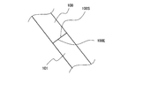
- FIG. 2 shows an explanatory view showing an enlarged example of the spiral code layer according to the present invention.
- the arrow in the figure indicates the longitudinal direction of the spiral cord layer, that is, the tire circumferential direction.
- the winding ends 100S and 100E of the reinforcing cord 100 are spirals measured along the tire surface in the tire width direction on both sides with the tire equator CL as the center. It exists within a range of 1/4 of the width SW of the cord layer 1, that is, within a range of 1/2 SW centering on the tire equator CL.
- FIG. 3 the width direction position and the magnitude of the tension acting in the spiral cord layer (using the aramid cord as the reinforcement cord) including the core cord layer between the upper layer and the lower layer as shown in FIGS.
- the graph which shows the relationship with is shown.
- the horizontal axis of the graph indicates the width direction position in the spiral cord layer having a width of 200 mm with reference to the center portion in the width direction of the spiral cord layer corresponding to the tire equator CL.
- the tension acting on the spiral cord layer which is an index of strain energy, is significantly reduced within the range of 50% on one side at the widthwise position centered on the tire equator CL, and in particular, 25 on one side. It can be seen that it is the smallest within the range of %.
- the repetitive strain during traveling that is applied to the winding ends 100S and 100E of the reinforcing cord 100 is minimized. This can be suppressed to the maximum, and as a result, the occurrence of separation starting from these winding ends 100S and 100E can be suppressed.
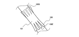
- the reinforcing cord 100 is usually spirally wound as a strip 101 formed by covering a bundle of one or two or more aligned with rubber with a predetermined inclination angle without a gap.
- the code layer 1 is formed. Therefore, for example, when the winding end 100E of the reinforcing cord 100 exists within the range of 1/2 SW centering on the tire equator CL, as shown in the drawing, the width direction center M of the winding end 100E of the reinforcing cord 100 is the tire equator. It means that it exists in the range of 1/2 SW around CL.
- both the winding end 100S at the winding start and the winding end 100E at the winding end need to exist within the range of 1/2 SW centering on the tire equator CL.
- the winding ends 100S and 100E of the reinforcing cord 100 are located on both sides with the tire equator CL as a center and within a range of 1/8 of the width SW of the spiral cord layer 1 measured along the tire surface in the tire width direction. It shall exist.
- the winding ends 100S and 100E of the reinforcing cord 100 are arranged so as to overlap each other so as to have an overlapping portion, but in the present invention, the joint portion of the winding ends 100S and 100E has such a structure.
- the form is not limited. 4 to 6 are explanatory views showing other configurations of the joint portions of the winding ends 100S and 100E.
- the winding ends 100S and 100E are arranged so as to abut each other without a gap so as not to have an overlapping portion.
- FIG. 5 shows a case where the strip 101 is composed of four reinforcing cords 100, and the positions of the cord ends of the four reinforcing cords 100 at the winding ends 100S and 100E are alternately changed along the cord longitudinal direction.
- the winding ends 100S and 100E are arranged so as to abut each other without a gap so as not to have an overlapping portion. This is because by making the positions of the cord ends of the adjacent reinforcing cords 100 different from each other along the cord longitudinal direction, the separation starting points can be separated from each other, and separation can be made less likely to occur.
- FIG. 6 also shows a case where the strip 101 is composed of four reinforcing cords 100, and the winding ends 100S and 100E of the reinforcing cords 100 are arranged so as to overlap each other in the figure. 2 is the same as that of 2, but by further making a cut in the rubber between the four reinforcing cords 100 at each of the winding ends 100S and 100E, the cord end positions of the four reinforcing cords 100 are made different in the cord width direction. There is. Also in this case, as in the case of FIG. 5, it is possible to separate the starting points of the separations to make it difficult for the separations to occur. In the present invention, as shown in FIGS.
- the reinforcing cord of the spiral cord layer has the above-mentioned predetermined inclination angle, and the winding end of the reinforcing cord is present in the above-mentioned predetermined range.
- the effect of can be obtained.
- Other configurations are not particularly limited and can be appropriately configured according to a conventional method.
- the spiral cord layer 1 is formed by spirally winding a rubber-cord composite in which one or a plurality of reinforcing cords, for example, 2 to 100, are aligned in parallel and covered with rubber. It is formed by rotating the core material cord layer 2 around the core material cord layer 2 in a spiral shape by rotating the core material cord layer 2.
- the number of reinforcing cords to be driven in the spiral cord layer 1 is preferably, for example, in the range of 5 to 60 cords/50 mm.
- the spiral cord layer 1 includes a core cord layer 2 between an upper layer 1A and a lower layer 1B, that is, a reinforcing cord is spirally wound around the core cord layer 2 to form a spiral cord.
- the core material cord layer 2 may not be provided.
- the core material cord layer 2 may be provided as a single layer or a plurality of layers, for example, 2 to 10 layers may be laminated.
- the core material cord layer 2 is manufactured by aligning a large number of core material cords in parallel, arranging unvulcanized rubbers on the upper and lower sides, and coating the core material cords with rubber.
- the number of core cords to be driven in the core cord layer 2 is preferably in the range of, for example, 5 to 60 cords/50 mm.
- the core material cord of the core material cord layer 2 may have an inclination angle of 40° or more and 90° or less with respect to the tire circumferential direction.
- the tension of the core material cord decreases, and the surplus until the core material cord breaks increases.
- the core material cord is less likely to break even when an obstacle is input.
- the inclination angle of the core cord of the core cord layer 2 is more preferably 50° or more and 90° or less with respect to the tire circumferential direction.
- the inclination angle of the reinforcing cord of the spiral cord layer 1 with respect to the tire circumferential direction is smaller than the inclination angle of the core material cord of the core material cord layer 2 with respect to the tire circumferential direction.
- the material of the reinforcing cord of the spiral cord layer 1 and the material of the core material cord of the core material cord layer 2 are not particularly limited, and various conventional general-purpose metal cords and organic fiber cords can be appropriately used. .. Specifically, for example, as the metal cord, a steel filament or a steel cord formed by twisting a plurality of steel filaments can be used. In this case, various designs of the twist structure of the cord are possible, and various cross-sectional structures, twist pitches, twist directions, and distances between adjacent filaments can be used. As the cross-sectional structure, various twist structures such as single twist, layer twist, and double twist can be adopted, and a flat cross section cord can also be used.
- the steel filament forming the steel cord contains iron as a main component and may contain various trace components such as carbon, manganese, silicon, phosphorus, sulfur, copper and chromium. Further, the surface of the steel filament may be plated with brass in order to improve the adhesiveness with rubber.
- aramid fiber aromatic polyamide fiber
- polyketone (PK) fiber polyparaphenylene benzobisoxazole (PBO) fiber
- polyarylate fiber or the like can be used.
- polyacrylonitrile (PAN)-based carbon fibers pitch-based carbon fibers, carbon fibers such as rayon-based carbon fibers (carbon fibers), glass fibers (glass fibers), rock fibers such as basalt fibers and andesite fibers (rock wool), etc.
- PAN polyacrylonitrile
- pitch-based carbon fibers carbon fibers such as rayon-based carbon fibers (carbon fibers), glass fibers (glass fibers), rock fibers such as basalt fibers and andesite fibers (rock wool), etc.
- PAN polyacrylonitrile
- pitch-based carbon fibers carbon fibers such as rayon-based carbon fibers (carbon fibers), glass fibers (glass fibers), rock fibers such as basalt fibers and andesite fibers (rock wool), etc.
- PAN polyacrylonitrile
- carbon fibers
- the rubber composition used for the coating rubber of the spiral cord layer 1 or the core cord layer 2 known rubber compositions can be used without any particular limitation.
- the rubber component of the rubber composition used for the coating rubber other than natural rubber; vinyl aromatic hydrocarbon/conjugated diene copolymer, polyisoprene rubber, butadiene rubber, butyl rubber, halogenated butyl rubber, ethylene-propylene rubber All known rubber components such as synthetic rubbers such as can be used.
- the rubber component may be used alone or in combination of two or more. From the viewpoint of the adhesive property with the metal cord and the breaking property of the rubber composition, the rubber component is composed of at least one of natural rubber and polyisoprene rubber, or contains 50% by mass or more of natural rubber and the balance is synthetic rubber. Is preferred.
- the rubber composition used for the coating rubber includes a filler such as carbon black and silica, a softening agent such as aroma oil, hexamethylenetetramine, pentamethoxymethylmelamine, methoxymethylated melamine such as hexamethylenemethylmelamine.
- a filler such as carbon black and silica
- a softening agent such as aroma oil, hexamethylenetetramine, pentamethoxymethylmelamine, methoxymethylated melamine such as hexamethylenemethylmelamine.
- Compounding agents usually used in the rubber industry such as methylene donors, vulcanization accelerators, vulcanization accelerating aids, antioxidants, etc. can be appropriately blended in the usual blending amounts.
- the rubber component is mixed with sulfur, an organic acid cobalt salt and various compounds. It may be prepared by kneading the agent and the like.
- the auxiliary belt layer 17 is arranged on the outer side of the spiral cord layer 1 in the tire radial direction.
- the auxiliary belt layer 17 can be provided as desired.
- the auxiliary belt layer 17 can be an inclined belt in which the belt cords form a predetermined angle with the tire circumferential direction, and is formed by aligning a large number of belt cords and coating them with rubber.
- the angle of the belt cord of the auxiliary belt layer 17 with respect to the tire circumferential direction is preferably in the range of 0° to 45°, more preferably 0° to 20°.
- the belt cord of the auxiliary belt layer 17 and the reinforcing cord of the upper layer 1A of the adjacent spiral cord layer 1 may be inclined in the same direction with reference to the tire circumferential direction, or may be inclined in the opposite direction. Good.
- the reinforcing cord of the auxiliary belt layer for example, a metal cord, particularly a steel cord is most commonly used, but an organic fiber cord may be used.
- the steel cord may be composed of a steel filament containing iron as a main component and various trace contents such as carbon, manganese, silicon, phosphorus, sulfur, copper and chromium.
- a steel monofilament cord may be used in addition to a cord formed by twisting a plurality of filaments.
- Various twisted structures of the steel cords can be designed, and various cross-sectional structures, twist pitches, twisting directions, and distances between adjacent steel cords can be used.
- a cord formed by twisting filaments of different materials can be adopted, and the cross-sectional structure is not particularly limited, and various twist structures such as single twist, layer twist, and double twist can be adopted.
- the width of the auxiliary belt layer 17 is preferably 40% to 115% of the tread width, and particularly preferably 50% to 70%.
- a belt under cushion rubber 18 is preferably provided on the inner side in the tire radial direction at the end of the spiral cord layer 1. As a result, the strain/temperature at the end of the spiral cord layer 1 can be reduced and the tire durability can be improved.
- the carcass 14 can adopt various configurations including a conventional structure, and may have either a radial structure or a bias structure.
- the carcass 14 it is preferable that the carcass ply made of a steel cord layer has one or two layers. Further, for example, the carcass maximum width position in the tire radial direction may be close to the bead portion 13 side or the tread portion 11 side.
- the maximum width position of the carcass 14 can be provided outside the bead base portion in the tire radial direction in a range of 50% to 90% with respect to the tire height.
- the carcass 14 is generally and preferably has a structure that extends between the pair of bead cores 15 without interruption. However, the carcass 14 is formed by using a pair of carcass pieces that extend from the bead core 15 and are interrupted near the tread portion 11. You can also
- the folded portion of the carcass 14 can adopt various structures.
- the folded end of the carcass 14 can be located on the inner side in the tire radial direction from the upper end of the bead filler 16, and the folded end of the carcass can be extended to the outer side in the tire radial direction from the upper end of the bead filler 16 or the tire maximum width position.
- the spiral cord layer 1 can be extended to the inner side in the tire width direction from the tire width direction end.
- the carcass ply has a plurality of layers, it is possible to change the position of the folded end of the carcass 14 in the tire radial direction.
- the carcass 14 may have a structure in which the carcass 14 is sandwiched between a plurality of bead core members without having the folded portion, and a structure wound around the bead core 15 may be adopted.
- the number of driving the carcass 14 is generally in the range of 5 to 60/50 mm, but is not limited to this.
- a circumferential cord layer (not shown) may be provided outside the spiral cord layer 1 and the auxiliary belt layer 17 in the tire radial direction.
- the truck/bus tire 10 of the present invention a known structure can be adopted for the sidewall portion 12 as well.
- the maximum tire width position can be provided outside the bead base portion in the tire radial direction in the range of 50% to 90% with respect to the tire height.
- the truck/bus tire 10 of the present invention is preferably formed as a smooth curve that is convex in the tire width direction without forming a recess that contacts the rim flange.
- the bead core 15 can adopt various structures such as a circular shape and a polygonal shape.
- the bead portion 13 may have a structure in which the carcass 14 is wound around the bead core 15 or a structure in which the carcass 14 is sandwiched by a plurality of bead core members.
- a bead filler 16 is arranged outside the bead core 15 in the tire radial direction.
- the bead filler 16 is composed of a plurality of rubber members divided in the tire radial direction. Good.
- the tread pattern may be a rib-shaped land-based pattern, a block pattern, an asymmetric pattern, or a rotational direction may be designated.
- the rib-like land portion main pattern is a pattern mainly including the rib-like land portion, which is divided in the tire width direction by one or more circumferential grooves or circumferential grooves and tread ends.
- the rib-shaped land portion refers to a land portion that extends in the tire circumferential direction without a lateral groove that traverses the tire width direction, but the rib-shaped land portion has a lateral groove that terminates in the sipe or the rib-shaped land portion. May be. It is considered that the radial tire has a high ground contact pressure especially under the use of a high internal pressure. Therefore, it is considered that the ground contact property on the wet road surface is improved by increasing the circumferential shear rigidity.
- a tread pattern composed only of rib-shaped land portions in a region of 80% of the tread width centered on the equatorial plane, that is, a pattern having no lateral groove may be used. it can. In such a pattern, drainage performance in this region contributes particularly to wet performance.
- the block pattern is a pattern that has a block land portion divided by a circumferential groove and a widthwise groove, and the tire of the block pattern has excellent basic on-ice performance and on-snow performance.
- the asymmetric pattern is a pattern in which the left and right tread patterns are asymmetric with respect to the equatorial plane.
- a negative ratio may be provided in the tire half portion on the vehicle mounting direction inner side and the vehicle mounting direction outer side with the equatorial plane as a boundary.
- the number of circumferential grooves may be different between the tire half on the inside in the mounting direction and the tire half on the outside in the vehicle mounting direction.
- the tread rubber is not particularly limited, and conventionally used rubber can be used. Further, the tread rubber may be formed of a plurality of rubber layers different in the tire radial direction, and may have a so-called cap/base structure, for example. As the plurality of rubber layers, those having different loss tangent, modulus, hardness, glass transition temperature, material, etc. can be used. Further, the ratio of the thickness of the plurality of rubber layers in the tire radial direction may be changed in the tire width direction, and only the circumferential groove bottom and the like may be different rubber layers from the periphery thereof.
- the tread rubber may be formed of a plurality of rubber layers different in the tire width direction, and may have a so-called split tread structure.
- the plurality of rubber layers those having different loss tangents, modulus, hardness, glass transition temperature, materials and the like can be used.
- the ratio of the length in the tire width direction of the plurality of rubber layers may be changed in the tire radial direction, and only in the vicinity of the circumferential groove, only near the tread end, only the shoulder land portion, only the center land portion, etc. Only a limited part of the area may be a rubber layer different from the surrounding area.
- the tread portion has a corner portion 11a formed at an end portion in the tire width direction.
- the tire shown in FIG. 1 is a tire for trucks and buses, but the present invention is not limited to this, and can be suitably applied to tires for passenger cars, construction vehicles, two-wheeled vehicles, aircraft, agriculture, and the like. it can. Further, the tire is not limited to a pneumatic tire, but can be applied to a solid tire or a non-pneumatic tire.
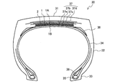
- FIG. 7 is a cross-sectional view in the tire width direction showing a configuration example of the passenger car tire of the present invention.
- the illustrated passenger car tire 20 includes a tread portion 21 that forms a ground contact portion, a pair of sidewall portions 22 that continuously extend inward in the tire radial direction on both sides of the tread portion 21, and a pair of sidewall portions 22. And a bead portion 23 continuous to the inner peripheral side.
- the tread portion 21, the sidewall portion 22, and the bead portion 23 are reinforced by a carcass 24 made of a single carcass ply extending from one bead portion 23 to the other bead portion 23 in a toroidal shape.
- bead cores 25 are embedded in the pair of bead portions 23, and the carcass 24 is folded around the bead cores 25 from the inside of the tire to the outside and locked. Further, a bead filler 26 is arranged outside the bead core 25 in the tire radial direction. ..
- a spiral cord layer 1 having a structure in which a reinforcing cord is spirally wound to form an upper layer 1A and a lower layer 1B on the tire radial direction outer side of the carcass 24,
- a core material cord layer 2 located between the upper layer 1A and the lower layer 1B and two auxiliary belt layers 27a and 27b are sequentially arranged.
- the reinforcing cord of the spiral cord layer has the predetermined inclination angle, and the winding end of the reinforcing cord is in the predetermined range. The intended effect of the present invention can be obtained.
- the carcass 24 can adopt various configurations including a conventional structure, and may have either a radial structure or a bias structure.
- the carcass ply composed of an organic fiber cord layer has one or two layers.
- the maximum width position of the carcass 24 in the tire radial direction may be close to the bead portion 23 side or the tread portion 21 side, for example.
- the maximum width position of the carcass 24 can be provided outside the bead base portion in the tire radial direction in a range of 50% to 90% with respect to the tire height.
- the carcass 24 generally has a structure in which it is possible to extend between the pair of bead cores 25 without interruption.
- the carcass 24 is formed by using a pair of carcass ply pieces that extend from the bead core 25 and are interrupted near the tread portion 21. It is also possible (not shown).
- the folded portion of the carcass 24 can adopt various structures.
- the folded end of the carcass 24 can be located inside the upper end of the bead filler 26 in the tire radial direction, and the folded end of the carcass 24 is outside the upper end of the bead filler 26 and the tire maximum width position in the tire radial direction.
- the spiral cord layer 1 can also be extended to the inner side in the tire width direction with respect to the tire width direction end.
- the position of the carcass 24 at the turning end can be different in the tire radial direction.
- the carcass 24 may have a structure in which the carcass 24 is sandwiched by a plurality of bead core members without having the folded-back portion, and a structure wound around the bead core 25 may be adopted.
- the number of driving the carcass 24 is generally in the range of 5 to 60/50 mm, but is not limited to this.
- the cap layer 27a arranged over the entire width of the spiral cord layer 1 or the layer arranged in a region covering both ends of the spiral cord layer 1.
- a layer 27b can be provided.
- the cap layer 27a and the layer layer 27b are usually formed by spirally winding a strip with a constant width formed by aligning a large number of cords and coating them with rubber in the tire circumferential direction.
- the cap layer 27a and the layer layer 27b may be provided alone or in combination. Alternatively, it may be a combination of two or more cap layers or two or more layer layers.
- the reinforcing cords of the cap layer 27a and the layer layer 27b Various materials can be used for the reinforcing cords of the cap layer 27a and the layer layer 27b. Typical examples are rayon, nylon, polyethylene naphthalate (PEN), polyethylene terephthalate (PET), aramid, glass fiber. , Carbon fiber, steel and the like. From the viewpoint of weight reduction, organic fiber cords are particularly preferable.
- the reinforcing cord a monofilament cord, a cord formed by twisting a plurality of filaments, or a hybrid cord formed by twisting filaments made of different materials can be used.
- a corrugated cord may be used as the reinforcing cord in order to increase the breaking strength.
- a high elongation cord having an elongation at break of 4.5 to 5.5% may be used.
- the cap layer 27a and the layer layer 27b are generally driven in the range of 20 to 60 lines/50 mm, but are not limited to this range. Further, in the cap layer 27a, distribution of rigidity, material, number of layers, driving density, and the like can be provided in the tire width direction, and for example, the number of layers can be increased only in the tire width direction end portion, while the center portion can be increased. Only the number of layers can be increased.
- the cap layer 27a and the layer layer 27b are configured as spiral layers.
- a plurality of core wires arranged in parallel to each other in a plane may be formed by a strip-shaped cord that is bundled by a wrapping wire while maintaining the parallel arrangement.
- the shape of the tread portion 21 in the case of a passenger car tire having a small width and a large diameter, a point P on the tread surface at the tire equatorial plane CL in the tire width direction cross section.
- the straight line parallel to the through tire width direction is m1
- the straight line passing through the ground contact edge E and parallel to the tire width direction is m2
- the distance in the tire radial direction between the straight line m1 and the straight line m2 is set to be the high LCR, and the tread width of the tire.
- Is TW, the ratio LCR/TW is preferably 0.045 or less.
- the crown portion of the tire is flattened (flattened), the ground contact area is increased, the input (pressure) from the road surface is relaxed, and the tire radial deflection The rate can be reduced, and the durability and wear resistance of the tire can be improved. Further, it is preferable that the tread end portion is smooth.
- the tread pattern may be a full lug pattern, a rib-shaped land-based pattern, a block pattern, an asymmetric pattern, or a rotation direction may be designated.
- the full lug pattern may be a pattern having a widthwise groove extending in the tire width direction from the vicinity of the equatorial plane to the ground contact end, and in this case, the circumferential groove may not be included.
- Such a pattern mainly composed of lateral grooves can effectively exhibit the performance on snow.
- the rib-shaped land main pattern is a pattern mainly composed of a rib-shaped land portion, which is divided in the tire width direction by one or more circumferential grooves or circumferential grooves and tread ends.
- the rib-shaped land portion refers to a land portion that extends in the tire circumferential direction without a lateral groove that traverses the tire width direction, but the rib-shaped land portion has a lateral groove that terminates in the sipe or the rib-shaped land portion. May be.
- the radial tire has a high ground contact pressure especially under the use of a high internal pressure. Therefore, it is considered that the ground contact property on the wet road surface is improved by increasing the circumferential shear rigidity.
- a tread pattern composed only of rib-shaped land portions in a region of 80% of the tread width centered on the equatorial plane, that is, a pattern having no lateral groove may be used. it can. In such a pattern, drainage performance in this region contributes particularly to wet performance.
- the block pattern is a pattern that has a block land portion divided by a circumferential groove and a widthwise groove, and the tire of the block pattern has excellent basic on-ice performance and on-snow performance.
- the asymmetric pattern is a pattern in which the left and right tread patterns are asymmetric with respect to the equatorial plane.
- a negative ratio may be provided in the tire half portion on the vehicle mounting direction inner side and the vehicle mounting direction outer side with the equatorial plane as a boundary.
- the number of circumferential grooves may be different between the tire half on the inside in the mounting direction and the tire half on the outside in the vehicle mounting direction.
- the tread rubber is not particularly limited, and conventionally used rubber can be used, or foamed rubber may be used. Further, the tread rubber may be formed of a plurality of rubber layers different in the tire radial direction, and may have a so-called cap/base structure, for example. As the plurality of rubber layers, those having different loss tangent, modulus, hardness, glass transition temperature, material, etc. can be used. Further, the ratio of the thickness of the plurality of rubber layers in the tire radial direction may be changed in the tire width direction, and only the circumferential groove bottom or the like may be a rubber layer different from the periphery thereof.
- the tread rubber may be formed of a plurality of rubber layers different in the tire width direction, and may have a so-called split tread structure.
- the plurality of rubber layers those having different loss tangents, modulus, hardness, glass transition temperature, materials and the like can be used.
- the ratio of the length in the tire width direction of the plurality of rubber layers may be changed in the tire radial direction, and only in the vicinity of the circumferential groove, only near the tread end, only the shoulder land portion, only the center land portion, etc. Only a limited part of the area may be a rubber layer different from the surrounding area.
- the sidewall portion 22 In the passenger car tire 20 of the present invention, a known structure can be adopted for the sidewall portion 22.
- the maximum tire width position can be provided outside the bead base portion in the tire radial direction in the range of 50% to 90% with respect to the tire height. Further, it may have a structure having a rim guard.
- the recess 23a that contacts the rim flange it is preferable that the recess 23a that contacts the rim flange be formed.
- the bead core 25 can adopt various structures such as a circular shape and a polygonal shape.
- the bead portion 23 may have a structure in which the carcass 24 is wound around the bead core 25 or a structure in which the carcass 24 is sandwiched by a plurality of bead core members.
- the bead filler 26 is arranged on the outer side in the tire radial direction of the bead core 25.
- the bead filler 26 may not be provided.
- the passenger car tire of the present invention may usually have an inner liner disposed in the innermost layer of the tire.
- the inner liner can be formed of a rubber layer containing butyl rubber as a main component and a film layer containing resin as a main component.
- a porous member may be arranged on the inner surface of the tire to reduce cavity resonance noise, or electrostatic flocking may be performed.
- the inner surface of the tire may be provided with a sealant member for preventing air leakage during puncture.
- the use of the passenger car tire 20 is not particularly limited. It can be applied to tires for summer, all season, winter, etc. Further, it can be used for a side-reinforcement type run flat tire having a crescent-shaped reinforcing rubber layer in the side wall portion 22 and a passenger car tire having a special structure such as a stud tire.
- FIG. 8 is a tire width direction cross-sectional view showing a configuration example of the construction vehicle tire of the present invention.
- a tread portion 31 forming a ground contact portion, a pair of sidewall portions 32 continuously extending inward in the tire radial direction on both sides of the tread portion 31, and each sidewall portion.
- a bead portion 33 continuous to the inner peripheral side of 32.
- the tread portion 31, the sidewall portion 32, and the bead portion 33 are reinforced by a carcass 34 made of a single carcass ply extending in a toroidal shape from one bead portion 33 to the other bead portion 33.
- a bead core 35 is embedded in each of the pair of bead portions 33, and the carcass 34 is folded around the bead core 35 from the inside of the tire to the outside and locked. Further, a bead filler 36 is arranged on the outer side of the bead core 35 in the tire radial direction.
- a spiral cord layer 1 having a structure in which an upper layer 1A and a lower layer 1B are formed by spirally winding a reinforcing cord on the tire radial direction outer side of a crown region of a carcass 34.
- the core material cord layer 2 located between the upper layer 1A and the lower layer 1B, and the four belt layers 37a to 37d are sequentially arranged.
- the reinforcing cord of the spiral cord layer has the above-mentioned predetermined inclination angle and the winding end of the reinforcing cord is within the above-mentioned predetermined range. Therefore, the intended effect of the present invention can be obtained.
- the four belt layers 37 correspond to the auxiliary belt layers.
- a tire for a construction vehicle is composed of four or six belt layers.
- the first belt layer and the second belt layer form an inner interlaced belt layer group and the third belt layer.
- the layer and the fourth belt layer form an intermediate intersecting belt layer group
- the fifth belt layer and the sixth belt layer form an outer intersecting belt layer group.
- the inner intersecting belt layer group is replaced with the spiral cord layer 1
- the auxiliary belt layers 37a to 37d are arranged as the intermediate intersecting belt layer group and the outer intersecting belt layer group.
- the first belt layer and the second belt layer are replaced with the spiral cord layer 1
- the third belt layer and the fourth belt layer are replaced with the auxiliary belt layers 37a, It may be 37b.
- the width of the spiral cord layer 1 is 25% or more and 70% or less of the width of the tread tread
- the width of the auxiliary belt layers 37a and 37b is the width of the tread tread. 55% or more and 90% or less
- the width of the auxiliary belt layers 37c and 37d can be 60% or more and 110% or less of the width of the tread tread surface.
- the inclination angle of the belt cords of the auxiliary belt layers 37a and 37b with respect to the carcass cord is 50° or more and 75° or less
- the inclination angle of the belt cords of the auxiliary belt layers 37c and 37d with respect to the carcass cord is 70°. The angle can be set to 85° or less.
- the auxiliary belt layer 37 is made of a rubberized layer of a reinforcing cord, and can be an inclined belt forming a predetermined angle with respect to the tire circumferential direction.
- a reinforcing cord of the inclined belt layer for example, a metal cord, particularly a steel cord is most commonly used, but an organic fiber cord may be used.
- the steel cord may be composed of a steel filament containing iron as a main component and various trace contents such as carbon, manganese, silicon, phosphorus, sulfur, copper and chromium.
- a steel monofilament cord may be used in addition to a cord formed by twisting a plurality of filaments.
- Various twisted structures of the steel cords can be designed, and various cross-sectional structures, twist pitches, twisting directions, and distances between adjacent steel cords can be used.
- a cord formed by twisting filaments of different materials can be adopted, and the cross-sectional structure is not particularly limited, and various twist structures such as single twist, layer twist, and double twist can be adopted.
- the inclination angle of the reinforcing cords of the other belt layers is preferably 10° or more with respect to the tire circumferential direction.
- the width of the maximum width inclined belt layer having the largest width among the auxiliary belt layers 37 is preferably 90% to 115% of the tread width, and particularly preferably 100% to 105%.
- a belt under cushion rubber 38 is preferably provided on the inner side in the tire radial direction of the end portion of the auxiliary belt layer 37.
- the carcass 34 can adopt various configurations including a conventional structure, and may have either a radial structure or a bias structure.
- the carcass 34 it is preferable that the carcass ply made of a steel cord layer has one or two layers. Further, for example, the carcass maximum width position in the tire radial direction may be close to the bead portion 33 side or the tread portion 31 side.
- the maximum width position of the carcass 34 can be provided outside the bead base portion in the tire radial direction in a range of 50% to 90% with respect to the tire height.
- the carcass 34 is generally and preferably has a structure that extends between the pair of bead cores 35 without interruption, but is formed using a pair of carcass pieces that extend from the bead core 35 and are interrupted near the tread portion 31. You can also
- the folded portion of the carcass 34 can adopt various structures.
- the folded end of the carcass 34 can be located on the inner side in the tire radial direction with respect to the upper end of the bead filler 36, and the folded end of the carcass 34 is on the outer side in the tire radial direction from the upper end of the bead filler 36 and the tire maximum width position.
- the spiral cord layer 1 can also be extended to the inner side in the tire width direction with respect to the tire width direction end.
- the position of the folded end of the carcass 34 in the tire radial direction can be different.
- the carcass 34 may have a structure in which the carcass 34 is sandwiched by a plurality of bead core members without having the folded portion, and a structure wound around the bead core 35 may be employed.
- the number of driving the carcass 34 is generally in the range of 5 to 60 pieces/50 mm, but is not limited to this.
- the maximum tire width position can be provided outside the bead base portion in the tire radial direction in the range of 50% to 90% with respect to the tire height.
- the bead core 35 can adopt various structures such as a circular shape and a polygonal shape.
- the bead portion 33 may have a structure in which the carcass 34 is wound around the bead core 35 or a structure in which the carcass 34 is sandwiched by a plurality of bead core members.
- the bead filler 36 is arranged outside the bead core 35 in the tire radial direction.
- the bead filler 36 may be composed of a plurality of rubber members divided in the tire radial direction. Good.
- the tread pattern may be a lug pattern, a block pattern, an asymmetric pattern, or may be a rotation direction designation.
- the lug pattern may have a width direction groove extending in the tire width direction from the vicinity of the equatorial plane to the ground contact end, and in this case, the circumferential groove may not be included.
- the block pattern is a pattern that has a block land portion divided by a circumferential groove and a widthwise groove. Particularly in the case of tires for construction vehicles, it is preferable to make the block large from the viewpoint of durability, and for example, the width of the block measured in the tire width direction is preferably 25% or more and 50% or less of the tread width.
- the asymmetric pattern is a pattern in which the left and right tread patterns are asymmetric with respect to the equatorial plane.
- a negative ratio may be provided in the tire half portion on the vehicle mounting direction inner side and the vehicle mounting direction outer side with the equatorial plane as a boundary.
- the number of circumferential grooves may be different between the tire half on the inside in the mounting direction and the tire half on the outside in the vehicle mounting direction.
- the tread rubber is not particularly limited, and conventionally used rubber can be used. Further, the tread rubber may be formed of a plurality of rubber layers different in the tire radial direction, and may have a so-called cap/base structure, for example. As the plurality of rubber layers, those having different loss tangent, modulus, hardness, glass transition temperature, material, etc. can be used. Further, the ratio of the thickness of the plurality of rubber layers in the tire radial direction may be changed in the tire width direction, and only the circumferential groove bottom or the like may be a rubber layer different from the periphery thereof.
- the tread rubber may be formed of a plurality of rubber layers different in the tire width direction, and may have a so-called split tread structure.
- the plurality of rubber layers those having different loss tangents, modulus, hardness, glass transition temperature, materials and the like can be used.
- the ratio of the length in the tire width direction of the plurality of rubber layers may be changed in the tire radial direction, and only in the vicinity of the circumferential groove, only near the tread end, only the shoulder land portion, only the center land portion, etc. Only a limited part of the area may be a rubber layer different from the surrounding area.
- the rubber gauge of the tread portion 31 is preferably thick from the viewpoint of durability, and is preferably 1.5% or more and 4% or less of the tire outer diameter, and more preferably 2% or more and 3% or less. ..
- the ratio of the groove area to the ground contact surface of the tread portion 31 (negative ratio) is preferably 20% or less. This is because the construction vehicle tire 30 is mainly used at low speed and in a dry area, and therefore it is not necessary to increase the negative rate because of drainage.
- the tire size of the construction vehicle tire is, for example, a rim diameter of 20 inches or more, and particularly a large tire has a rim diameter of 40 inches or more.
- auxiliary belt layer is arranged on the outer side in the tire radial direction.
- Core material cord of core material cord layer and belt cord of auxiliary belt layer A steel cord with a 1+6 structure that uses a steel filament with a wire diameter of 1.13 mm.
- Inclination angle of steel cord of core cord layer 50° to the longitudinal direction of the reinforcing member.
- Inclination angle of steel cord of auxiliary belt layer 16° to the longitudinal direction of the reinforcing member.
- tilt direction of steel cord of auxiliary belt layer In the same direction as the reinforcing cord in the upper layer of the adjacent spiral cord layer.
- the “applicable rim” refers to a rim defined by the following standards according to the size of the tire.
- the “specified internal pressure” means an air pressure specified in accordance with the maximum load capacity in the following standards.
- the standard refers to an industrial standard that is effective in regions where tires are produced or used. For example, in the United States, “THE TIRE AND RIM ASSOCIATION INC. YEAR BOOK”, and in Europe, “THE EUROPEAN TYRE AND AND RIM Technical Organization's STANDARDS MANUAL”, and in Japan, the Japan Automobile Tire Manufacturers Association's “JATMA YEAR BOOK”.
Landscapes
- Engineering & Computer Science (AREA)
- Mechanical Engineering (AREA)
- Tires In General (AREA)
Abstract
L'invention concerne un pneu à durabilité améliorée par absence d'apparition de séparation au niveau des extrémités d'enroulement de câbles de renfort dans une couche à câbles en spirales. Le pneu est pourvu d'une carcasse à extension toroïdale entre deux talons et d'une couche à câbles en spirales qui, dans la direction radiale du pneu, est disposée à l'extérieur de la section de sommet de la carcasse et qui forme une couche supérieure et une couche inférieure, par enroulement en spirale de câbles de renfort. L'angle d'inclinaison des câbles de renfort (100) dans la couche à câbles en spirales (1) vaut de 10° à 45° par rapport à la direction circonférentielle de pneu et les extrémités d'enroulement (100S, 100E) du câble de renfort sont présentes dans la plage de 1/4 de la largeur SW de la couche à câbles en spirales des deux côtés de l'équateur de pneu, mesurées le long de la surface de pneu dans la direction de largeur de pneu.
Applications Claiming Priority (2)
| Application Number | Priority Date | Filing Date | Title |
|---|---|---|---|
| JP2018232859A JP2020093661A (ja) | 2018-12-12 | 2018-12-12 | タイヤ |
| JP2018-232859 | 2018-12-12 |
Publications (1)
| Publication Number | Publication Date |
|---|---|
| WO2020121731A1 true WO2020121731A1 (fr) | 2020-06-18 |
Family
ID=71075647
Family Applications (1)
| Application Number | Title | Priority Date | Filing Date |
|---|---|---|---|
| PCT/JP2019/044742 Ceased WO2020121731A1 (fr) | 2018-12-12 | 2019-11-14 | Pneu |
Country Status (2)
| Country | Link |
|---|---|
| JP (1) | JP2020093661A (fr) |
| WO (1) | WO2020121731A1 (fr) |
Cited By (1)
| Publication number | Priority date | Publication date | Assignee | Title |
|---|---|---|---|---|
| CN115515800A (zh) * | 2020-06-25 | 2022-12-23 | 横滨橡胶株式会社 | 充气轮胎 |
Families Citing this family (1)
| Publication number | Priority date | Publication date | Assignee | Title |
|---|---|---|---|---|
| EP4431310B1 (fr) * | 2021-11-10 | 2025-12-24 | Bridgestone Corporation | Pneu |
Citations (15)
| Publication number | Priority date | Publication date | Assignee | Title |
|---|---|---|---|---|
| JPH04173404A (ja) * | 1990-11-06 | 1992-06-22 | Sumitomo Rubber Ind Ltd | 空気入りタイヤ |
| DE4214197A1 (de) * | 1992-04-30 | 1993-11-04 | Continental Ag | Verfahren zum herstellen eines guertelpakets fuer einen fahrzeugluftreifen |
| JPH0939513A (ja) * | 1995-07-26 | 1997-02-10 | Yokohama Rubber Co Ltd:The | 空気入りラジアルタイヤ |
| JPH10109502A (ja) * | 1996-10-07 | 1998-04-28 | Yokohama Rubber Co Ltd:The | 空気入りラジアルタイヤ |
| JPH10217716A (ja) * | 1997-02-10 | 1998-08-18 | Yokohama Rubber Co Ltd:The | 乗用車用空気入りラジアルタイヤ |
| JPH1134609A (ja) * | 1997-05-23 | 1999-02-09 | Yokohama Rubber Co Ltd:The | 空気入りラジアルタイヤ |
| JPH11189009A (ja) * | 1997-12-26 | 1999-07-13 | Yokohama Rubber Co Ltd:The | 空気入りタイヤ |
| JPH11245618A (ja) * | 1998-03-04 | 1999-09-14 | Bridgestone Corp | 空気入りタイヤ |
| JP2000033806A (ja) * | 1998-07-17 | 2000-02-02 | Yokohama Rubber Co Ltd:The | 空気入りラジアルタイヤ |
| JP2000033805A (ja) * | 1998-07-17 | 2000-02-02 | Yokohama Rubber Co Ltd:The | 空気入りラジアルタイヤ |
| JP2006137287A (ja) * | 2004-11-11 | 2006-06-01 | Yokohama Rubber Co Ltd:The | ゴム・コード複合材 |
| JP2010132200A (ja) * | 2008-12-05 | 2010-06-17 | Bridgestone Corp | 空気入りタイヤ |
| WO2016190048A1 (fr) * | 2015-05-25 | 2016-12-01 | 株式会社ブリヂストン | Élément de renforcement pour pneumatique, et pneumatique mettant en œuvre celui-ci |
| WO2016190152A1 (fr) * | 2015-05-25 | 2016-12-01 | 株式会社ブリヂストン | Élément de renforcement pour pneumatique, et pneumatique mettant en œuvre celui-ci |
| WO2018078268A1 (fr) * | 2016-10-26 | 2018-05-03 | Compagnie Generale Des Etablissements Michelin | Armature de sommet de pneumatique pour avion |
-
2018
- 2018-12-12 JP JP2018232859A patent/JP2020093661A/ja active Pending
-
2019
- 2019-11-14 WO PCT/JP2019/044742 patent/WO2020121731A1/fr not_active Ceased
Patent Citations (15)
| Publication number | Priority date | Publication date | Assignee | Title |
|---|---|---|---|---|
| JPH04173404A (ja) * | 1990-11-06 | 1992-06-22 | Sumitomo Rubber Ind Ltd | 空気入りタイヤ |
| DE4214197A1 (de) * | 1992-04-30 | 1993-11-04 | Continental Ag | Verfahren zum herstellen eines guertelpakets fuer einen fahrzeugluftreifen |
| JPH0939513A (ja) * | 1995-07-26 | 1997-02-10 | Yokohama Rubber Co Ltd:The | 空気入りラジアルタイヤ |
| JPH10109502A (ja) * | 1996-10-07 | 1998-04-28 | Yokohama Rubber Co Ltd:The | 空気入りラジアルタイヤ |
| JPH10217716A (ja) * | 1997-02-10 | 1998-08-18 | Yokohama Rubber Co Ltd:The | 乗用車用空気入りラジアルタイヤ |
| JPH1134609A (ja) * | 1997-05-23 | 1999-02-09 | Yokohama Rubber Co Ltd:The | 空気入りラジアルタイヤ |
| JPH11189009A (ja) * | 1997-12-26 | 1999-07-13 | Yokohama Rubber Co Ltd:The | 空気入りタイヤ |
| JPH11245618A (ja) * | 1998-03-04 | 1999-09-14 | Bridgestone Corp | 空気入りタイヤ |
| JP2000033806A (ja) * | 1998-07-17 | 2000-02-02 | Yokohama Rubber Co Ltd:The | 空気入りラジアルタイヤ |
| JP2000033805A (ja) * | 1998-07-17 | 2000-02-02 | Yokohama Rubber Co Ltd:The | 空気入りラジアルタイヤ |
| JP2006137287A (ja) * | 2004-11-11 | 2006-06-01 | Yokohama Rubber Co Ltd:The | ゴム・コード複合材 |
| JP2010132200A (ja) * | 2008-12-05 | 2010-06-17 | Bridgestone Corp | 空気入りタイヤ |
| WO2016190048A1 (fr) * | 2015-05-25 | 2016-12-01 | 株式会社ブリヂストン | Élément de renforcement pour pneumatique, et pneumatique mettant en œuvre celui-ci |
| WO2016190152A1 (fr) * | 2015-05-25 | 2016-12-01 | 株式会社ブリヂストン | Élément de renforcement pour pneumatique, et pneumatique mettant en œuvre celui-ci |
| WO2018078268A1 (fr) * | 2016-10-26 | 2018-05-03 | Compagnie Generale Des Etablissements Michelin | Armature de sommet de pneumatique pour avion |
Cited By (1)
| Publication number | Priority date | Publication date | Assignee | Title |
|---|---|---|---|---|
| CN115515800A (zh) * | 2020-06-25 | 2022-12-23 | 横滨橡胶株式会社 | 充气轮胎 |
Also Published As
| Publication number | Publication date |
|---|---|
| JP2020093661A (ja) | 2020-06-18 |
Similar Documents
| Publication | Publication Date | Title |
|---|---|---|
| JP6718867B2 (ja) | タイヤ用補強部材およびこれを用いたタイヤ | |
| JP6704332B2 (ja) | ゴム−コード複合体、タイヤ用補強部材およびこれを用いたタイヤ | |
| JP6423312B2 (ja) | タイヤ用補強部材およびこれを用いたタイヤ | |
| JP6701060B2 (ja) | ゴム−コード複合体、タイヤ用補強部材およびこれを用いたタイヤ | |
| JP6811684B2 (ja) | タイヤ | |
| JPWO2018147450A1 (ja) | タイヤ | |
| WO2020121731A1 (fr) | Pneu | |
| CN109982866B (zh) | 轮胎 | |
| WO2019116650A1 (fr) | Pneu | |
| WO2018097083A1 (fr) | Pneumatique | |
| JP2019001195A (ja) | 補強部材およびそれを用いたタイヤ | |
| US20200108664A1 (en) | Reinforcement member and tire using same | |
| WO2018230265A1 (fr) | Pneumatique | |
| JPWO2019117010A1 (ja) | タイヤ | |
| CN109996686B (zh) | 轮胎 | |
| JP2019001421A (ja) | タイヤ | |
| JPWO2019116841A1 (ja) | タイヤ用補強部材およびこれを用いたタイヤ | |
| JPWO2019116766A1 (ja) | タイヤ用補強部材およびこれを用いたタイヤ |
Legal Events
| Date | Code | Title | Description |
|---|---|---|---|
| 121 | Ep: the epo has been informed by wipo that ep was designated in this application |
Ref document number: 19895437 Country of ref document: EP Kind code of ref document: A1 |
|
| NENP | Non-entry into the national phase |
Ref country code: DE |
|
| 122 | Ep: pct application non-entry in european phase |
Ref document number: 19895437 Country of ref document: EP Kind code of ref document: A1 |