WO2020121744A1 - Dispositif de filtrage et filtre - Google Patents
Dispositif de filtrage et filtre Download PDFInfo
- Publication number
- WO2020121744A1 WO2020121744A1 PCT/JP2019/045130 JP2019045130W WO2020121744A1 WO 2020121744 A1 WO2020121744 A1 WO 2020121744A1 JP 2019045130 W JP2019045130 W JP 2019045130W WO 2020121744 A1 WO2020121744 A1 WO 2020121744A1
- Authority
- WO
- WIPO (PCT)
- Prior art keywords
- filter
- lid
- filter body
- filter according
- side wall
- Prior art date
- Legal status (The legal status is an assumption and is not a legal conclusion. Google has not performed a legal analysis and makes no representation as to the accuracy of the status listed.)
- Ceased
Links
Images








Classifications
-
- B—PERFORMING OPERATIONS; TRANSPORTING
- B01—PHYSICAL OR CHEMICAL PROCESSES OR APPARATUS IN GENERAL
- B01D—SEPARATION
- B01D46/00—Filters or filtering processes specially modified for separating dispersed particles from gases or vapours
- B01D46/24—Particle separators, e.g. dust precipitators, using rigid hollow filter bodies
- B01D46/2403—Particle separators, e.g. dust precipitators, using rigid hollow filter bodies characterised by the physical shape or structure of the filtering element
- B01D46/2411—Filter cartridges
- B01D46/2414—End caps including additional functions or special forms
-
- B—PERFORMING OPERATIONS; TRANSPORTING
- B01—PHYSICAL OR CHEMICAL PROCESSES OR APPARATUS IN GENERAL
- B01D—SEPARATION
- B01D46/00—Filters or filtering processes specially modified for separating dispersed particles from gases or vapours
- B01D46/0084—Filters or filtering processes specially modified for separating dispersed particles from gases or vapours provided with safety means
- B01D46/0091—Including arrangements for environmental or personal protection
-
- B—PERFORMING OPERATIONS; TRANSPORTING
- B01—PHYSICAL OR CHEMICAL PROCESSES OR APPARATUS IN GENERAL
- B01D—SEPARATION
- B01D46/00—Filters or filtering processes specially modified for separating dispersed particles from gases or vapours
- B01D46/66—Regeneration of the filtering material or filter elements inside the filter
- B01D46/79—Regeneration of the filtering material or filter elements inside the filter by liquid process
-
- B—PERFORMING OPERATIONS; TRANSPORTING
- B01—PHYSICAL OR CHEMICAL PROCESSES OR APPARATUS IN GENERAL
- B01D—SEPARATION
- B01D46/00—Filters or filtering processes specially modified for separating dispersed particles from gases or vapours
- B01D46/88—Replacing filter elements
Definitions
- the present invention relates to a filter for collecting dust in a fluid and a filter device using the filter, and more particularly to a structure for preventing exposure due to dust during filter replacement.
- the filter device generally includes a housing, a filter housed in the housing, an introduction unit that introduces a fluid to be filtered into the housing, and a discharge unit that discharges the fluid filtered by the filter. Dust contained in the fluid introduced from the introduction part is collected by the filter material of the filter, and the fluid from which the dust is removed becomes a clean fluid and is discharged from the discharge part.
- Patent Documents 1 and 2 described later show examples of hollow, cylindrical filters.
- the filter will become clogged as dust is repeatedly collected, so it will be necessary to replace it when it has been used for a certain period of time.
- it is necessary to pay close attention so that the worker is not exposed by the scattering of dust adhering to the used filter.
- the filter is replaced through a vinyl bag so that the used filter is not exposed in the open space and dust is scattered. Exposure to water is prevented.
- WOC wet open change
- FIG. 20A is a schematic configuration diagram of the filter device.
- the filter device 100 includes a housing 10 and a filter 1 housed in the housing 10.
- the housing 10 has an introduction part 14 into which the fluid X (dust-containing air flow) to be filtered is introduced, and a discharge part 15 from which the fluid Y (clean air flow) filtered by the filter 1 is discharged.
- the dust-containing airflow X that has flowed into the primary space P inside the filter 1 from the introduction portion 14 is filtered in the process of passing through the filter 1 from the inner side to the outer side as indicated by the arrow, and dust in the airflow is generated.
- the airflow from which dust has been removed and which has flowed out to the secondary space S becomes a clean airflow Y and is discharged from the discharge portion 15.
- FIG. 20(b) to 21(h) show an outline of a procedure for replacing the filter 1 in the filter device 100.
- the valves (not shown) provided upstream of the introduction unit 14 and downstream of the discharge unit 15 are closed.
- the liquid W to be injected may be water or a liquid other than water.
- the injected liquid W enters the primary space P of the filter 1, and the liquid level of the liquid W rises as it is injected.
- the primary space P is filled with the liquid W as shown in FIG.
- the entire inner surface of the filter 1, that is, the dust adhering surface is submerged in the liquid W.
- the injection of the liquid W is stopped, and subsequently, as shown in FIG.
- the liquid W is drained from the introduction part 14.
- the inner surface (dust adhering surface) of the filter 1 is the wet surface m, as shown in FIG.
- the cover 10a forming the housing 10 and the base 10b are separated, and the cover 10a is removed. Further, the fixing member (not shown) that fixes the filter 1 to the base 10b is also removed.
- the cover 10a By removing the cover 10a, as shown in FIG. 21(g), the filter 1 whose inner surface is wet is exposed to the open space. In this state, as shown in FIG. 21(h), the used filter 1 is taken out and a new filter 1'is set on the base 10b.
- the filter 1 includes a cylindrical filter body 2 and a lid body 3 attached to an upper opening of the filter body 2.
- the filter body 2 includes an inner cylinder, an outer cylinder, and a filter medium housed between them (not shown).
- the lid 3 has a top plate 31 that covers the upper opening of the filter body 2 and a side wall 32 that is annularly provided on the peripheral edge of the top plate 31, and the side wall 32 is fitted to the upper outer surface of the filter body 2.
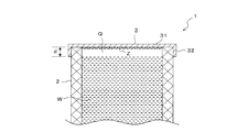
- the dust Z attached to the back side of the top plate 31 of the lid 3 cannot be wetted by the liquid W. Therefore, when the filter is replaced, the dust Z is removed from the filter 1 taken out. The dried dust Z may be scattered and the worker may be exposed.
- the side wall 32 of the lid body 3 is removed, the air pool Q will not occur, but without the side wall 32, the lid body 3 cannot be firmly attached to the filter body 2, and the lid body 3 and the filter body 2 will be separated from each other. It is virtually impossible to omit the side wall 32 because the sealing performance between them is also impaired.
- Patent Document 4 it is described that a slit is provided in a part of the lid that covers the upper opening of the filter in order to prevent air accumulation in the upper space inside the filter.
- this structure is useful in a filter device in which a fluid flows from the outside to the inside of the filter as in this document, but since the inside of the filter communicates with the outside through a slit, it is shown in FIG. Such a filter cannot be applied to a filter device in which fluid flows from the inside to the outside of the filter.
- the present invention solves the problems peculiar to the WOC method as described above, and prevents the accumulation of air in the internal space of the filter at the time of wet down, thereby eliminating the wet leakage of the adhered dust. ,
- the challenge is to enable more thorough exposure control.
- the filter according to the present invention includes a hollow filter main body and a lid attached to the upper part of the filter main body.
- the lid has a top plate that covers the upper opening of the filter body, and a side wall that fits with the upper portion of the filter body.
- the lower end of the side wall is located below the upper end of the filter body.
- the upper opening of the filter body is provided with a ceiling portion that can come into contact with the liquid injected into the inside of the filter body, and the lower surface of the ceiling portion is located at the lower end of the side wall or at a position lower than that.
- the filter device includes the filter described above and a housing that houses the filter.
- the filter is arranged to allow fluid to flow from the inside to the outside of the filter body.
- the housing includes a base on which the filter is installed, and a cover that is detachably attached to the base and covers the filter.
- the ceiling portion is present in the upper part of the internal space of the filter body, and the lower surface of the ceiling portion is at the same position as or lower than the lower end of the side wall of the lid, it is possible to inject liquid Accordingly, the air in the internal space can be allowed to escape through the filter body without being obstructed by the side wall. As a result, no air pool is formed in the upper part of the internal space, and the injected liquid reliably contacts the lower surface of the ceiling part. As a result, the dust adhering to the inner surface of the filter body and the lower surface of the ceiling part is wetted without leakage, and therefore, when the filter is replaced, it is possible to prevent the generation of exposure due to scattering of unwetted dust. it can.
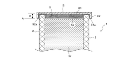
- FIG. 1 is a sectional view showing a schematic configuration of a filter of the present invention.
- FIG. 2 is a partial cross-sectional view showing a state where the inner space of the filter is filled with liquid.
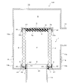
- FIG. 3 is a cross-sectional view showing a schematic configuration of a filter device accommodating a filter.
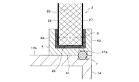
- FIG. 4 is an enlarged cross-sectional view of an essential part showing the seal structure of the lower part of the filter body.
- FIG. 5 is sectional drawing which shows the hollow produced in the lower surface of a ceiling part.
- FIG. 6 is a partial cross-sectional view showing another embodiment of the present invention.
- FIG. 7 is a partial cross-sectional view showing another embodiment of the present invention.
- FIG. 8 is a partial cross-sectional view showing another embodiment of the present invention.
- FIG. 1 is a sectional view showing a schematic configuration of a filter of the present invention.
- FIG. 2 is a partial cross-sectional view showing a state where the inner space of the filter is filled
- FIG. 9 is a partial cross-sectional view showing another embodiment of the present invention.
- FIG. 10 is a partial cross-sectional view showing another embodiment of the present invention.
- FIG. 11 is a partial cross-sectional view showing another embodiment of the present invention.
- FIG. 12 is a partial cross-sectional view showing another embodiment of the present invention.
- FIG. 13 is a partial cross-sectional view showing another embodiment of the present invention.
- FIG. 14 is a partial cross-sectional view showing another embodiment of the present invention.
- FIG. 15 is a cross-sectional view showing a reference example adopting a solution different from the present invention.
- FIG. 16 is a cross-sectional view showing a reference example adopting a solution means different from the present invention.
- FIG. 17 is a cross-sectional view showing a reference example adopting a solving means different from the present invention.
- FIG. 18 is a sectional view showing a reference example adopting a solution means different from the present invention.
- FIG. 19 is a cross-sectional view showing a reference example adopting a solving means different from the present invention.
- FIG. 20 is a diagram illustrating a procedure of a filter replacement method according to the WOC method.
- FIG. 21 is a diagram for explaining the procedure of the filter replacement method according to the WOC method (continuation of FIG. 20).
- FIG. 22 is a partial cross-sectional view showing a state in which an air pocket is generated in the internal space of the filter body.
- the filter 1 shows an example of a filter according to the present invention.
- the filter 1 includes a hollow filter body 2, a lid 3 attached to an upper portion of the filter body 2, a flange 4 attached to a lower portion of the filter body 2, and a ceiling portion 5 which is a feature of the present invention. ..
- the filter 1 constitutes a HEPA filter (High Efficiency Particulate Air Filter).
- the filter body 2 is formed in a cylindrical shape and has an upper opening 21 on the upper side and a lower opening 22 on the lower side. As shown in FIG. 4, the filter body 2 includes an inner cylinder 27, an outer cylinder 28, and a filter medium 26 housed therebetween.
- the inner cylinder 27 and the outer cylinder 28 are made of a cylindrical metal plate having a large number of holes through which the fluid passes.
- the filter medium 26 is made of, for example, a pleated filter medium or a granular filter medium.
- the lid 3 is made of metal or resin and has a circular top plate 31 that covers the upper opening 21 of the filter body 2 and an annular side wall 32 provided on the periphery of the top plate 31.
- the side wall 32 is an outer wall that is fitted to the upper portion of the filter body 2 and is located outside the filter body 2.
- the lower end 32a of the side wall 32 is located below the upper end 2a of the filter body 2.
- the flange 4 is made of metal or resin, and has an annular bottom wall 41, annular side walls 42 and 43 provided on the bottom wall 41, and an opening 44 surrounded by the side wall 43.
- the bottom wall 41 is placed on the base 10b of the housing 10, as shown in FIG.
- the side wall 42 is an outer wall that fits with the lower portion of the filter body 2 and is located outside the filter body 2.
- the side wall 43 is an inner wall that fits with the lower portion of the filter body 2 and is located inside the filter body 2.
- the opening 44 is formed in a circular shape and communicates with the internal space of the filter body 2.
- the gap between the flange 4 and the filter body 2 is filled with resin 6, and the resin 6 seals the flange 4 and the filter body 2.
- the ceiling 5 is made of resin filled on the back side of the lid 3.
- the lid body 3 is placed upside down with respect to FIG. Fill up to the position of the lower end 32a.
- This resin is filled not only in the upper opening 21 of the filter body 2 but also in the gap between the lid 3 and the filter body 2.
- the lower surface 5a of the ceiling 5 thus formed is a flat surface parallel to the top plate 31 of the lid 3, and is at the same position A as the lower end 32a of the side wall 32 of the lid 3.
- the lower surface 5a may be located below the lower end position A of the side wall 32 by a predetermined distance.
- the ceiling portion 5 may be formed by resin molding using a mold.
- FIG. 2 shows a state in which the liquid W for wet down (for example, water) is injected into the internal space (primary space) of the filter 1 of FIG. 1 to fill the internal space with water.
- the liquid W for wet down for example, water
- the internal space primary space
- the filter 1 of FIG. 1 to fill the internal space with water.
- the ceiling portion 5 made of resin in the upper area (range d) of the internal space where the air pocket Q (FIG. 22) has conventionally been generated, and the lower surface 5a of the ceiling portion 5 is The position corresponds to the lower end position A of the side wall 32 of the lid 3. Therefore, with the injection of the liquid W, the air in the internal space can be allowed to escape through the filter body 2 without being obstructed by the side wall 32.
- the filter device 100 includes a filter 1 and a housing 10 that houses the filter.
- the filter 1 housed in the housing 10 is not limited to the one shown in FIG. 1, and may be various filters described later.
- the housing 10 is composed of a cover 10a that covers the filter 1 and a base 10b on which the filter 1 is installed.
- the filter 1 is detachably fixed to the base 10b by a fixing member such as a bolt (not shown).
- the cover 10a is detachably attached to the base 10b by the connecting tool 8.
- the base 10b is provided with an introduction part 14 into which the dust-containing airflow is introduced, and the cover 10a is provided with an exhaust part 15 from which the clean airflow filtered by the filter 1 is discharged.
- the flow of the airflow in the filter device 100 of FIG. 3 is the same as the flow of the airflow shown in FIG. 20A, and the airflow is from the inside (primary side space P) of the filter body 2 to the outside (secondary side space S). Flows. That is, the dust-containing airflow that has flowed into the primary space P of the filter 1 from the introduction portion 14 is filtered in the process of passing through the filter 1 from the inside to the outside, and becomes a clean airflow and is discharged from the discharge portion 15. The dust in the air flow is collected by the filter body 2, but the dust also adheres to the inner surface of the filter body 2 and the lower surface 5a of the ceiling portion 5.
- the liquid W when the liquid is injected into the primary space P during the wet down process, the liquid W completely fills the space as described with reference to FIG. 2, so that the liquid W adheres to the inner surface of the filter body 2 and the lower surface 5a of the ceiling portion 5.
- the dust thus formed is in a wet state without leaking.
- a sponge packing such as EPDM (ethylene propylene diene rubber) is interposed between the lower surface of the filter and the filter installation surface of the housing.
- EPDM ethylene propylene diene rubber
- the seal member 7 formed of an O-ring is provided between the bottom wall 41 of the flange 4 of the filter 1 and the base 10b.
- the O-ring has less deterioration in shape restoration due to deterioration over time and can maintain the sealing performance for a long period of time. Therefore, the O-ring has an advantage that the same sealing performance can be obtained by anyone.
- an X ring or a lip seal may be used as the seal member 7 instead of the O ring.
- the seal member 7 may be provided on the base 10b side, but in the present embodiment, it is attached to the annular groove 41a (FIG. 4) formed on the lower surface of the bottom wall 41 of the flange 4. That is, the seal member 7 is a component of the filter 1. It is also possible to prepare another member having an annular groove in which the seal member 7 is mounted and attach this to the flange 4.
- the annular seal member 7 is provided at a position closer to the inner cylinder 27 than the center of the region U between the inner cylinder 27 and the outer cylinder 28 of the filter body 2.
- the sealing member 7 receives a pressing force from the inner cylinder 27 and is strongly pressed between the flange 4 and the base 10b, so that sufficient sealing performance can be secured.
- the seal member 7 is provided at a position near the inner cylinder 27, a small seal member having a short ring diameter can be used.
- the seal member 7 is arranged directly below the inner cylinder 27 in FIG. 4, this is an example, and the seal member 7 may be arranged at any position near the inner cylinder 27.
- the lower surface 5a of the ceiling part 5 does not become a completely flat surface, and the resin shrinks as shown in FIG.
- Large and small depressions R1 and R2 may occur due to the above. Since the recesses R1 and R2 are located above the lower end position A of the side wall 32, when the liquid W is injected during the wet down, the recesses R1 and R2 serve as an air reservoir, and the liquid W is separated from the recesses R1 and R2. It may not reach inside. For this reason, if dust adheres to the depressions R1 and R2, the dust is not wetted by the liquid W, and there is a concern that exposure may occur during filter replacement.
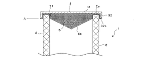
- FIGS. 6 and 7 an embodiment as shown in FIGS. 6 and 7 can be considered.
- the lower surface 5b of the ceiling portion 5 is formed in a conical shape, a pyramidal shape, or a roof shape.
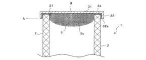
- the lower surface 5c of the ceiling portion 5 is formed in a dome shape or a saddle shape.
- the lower surfaces 5b and 5c of the ceiling portion 5 are projecting surfaces that project downward, and each projecting surface is located below the lower end position A of the side wall 32.
- the ceiling portion 5 is formed by resin molding.
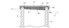
- FIG. 8 an embodiment as shown in FIG. 8 can be considered.
- the lower surface 5d of the ceiling portion 5 is formed as an inclined surface, and this inclined surface is located below the lower end position A of the side wall 32.
- the ceiling portion 5 is formed by resin molding.
- the lower surface 5 e of the ceiling portion 5 is formed into an asymmetrical conical, pyramidal, or roof-shaped protruding surface, and this protruding surface is located below the lower end position A of the side wall 32.
- the ceiling portion 5 is formed by resin molding.
- the lower surface 5e may be an asymmetrical dome-shaped or saddle-shaped protruding surface.
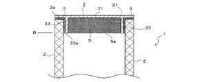
- FIG. 10 shows another embodiment of the lid 3.
- the side wall 32 of the lid 3 is an outer wall provided on the peripheral edge of the top plate 31, and is located outside the filter body 2.
- the side wall 33 of the lid 3 is an inner wall provided near the peripheral edge of the top plate 31 and is located inside the filter body 2.
- the lower surface 5a of the ceiling portion 5 is located at the same position as the position B of the lower end 33a of the side wall 33, but may be located below the lower end position B by a predetermined distance.
- the embodiment of FIGS. 6 to 9 may be adopted for the ceiling portion 5.
- FIG. 11 shows still another embodiment of the lid body 3.
- the side wall of the lid body 3 is composed of the outer wall 32 of FIG. 1 and the inner wall 33 of FIG. 10.
- the lower end 33a of the inner wall 33 is located below the lower end 32a of the outer wall 32.
- the lower surface 5a of the ceiling portion 5 is at the same position B as the lower end 33a of the inner wall 33. Also in this case, the lower surface 5a may be located below the lower end position B of the inner wall 33 by a predetermined distance. Further, the embodiment of FIGS. 6 to 9 may be adopted for the ceiling portion 5.
- FIG. 12 shows another embodiment of the ceiling part 5.
- the ceiling portion 5 is made of a resin-molded product in advance and is attached to the lid body 3 afterwards.
- a mounting method for example, a method in which the ceiling portion 5 is fitted inside the inner wall 33 and fixed to the top plate 31 with an adhesive or the like can be considered.
- the outer wall 32 and the inner wall 33 have the same length, they may have different lengths.
- the lower surface 5f of the ceiling portion 5 is below the position A of the lower end 32a of the outer wall 32.
- the lower surface 5f of the ceiling portion 5 has the same shape as the lower surface 5b of FIG. 6, but the lower surface 5f has the same shape as the lower surfaces 5c to 5e of FIGS. 7 to 9. Good.
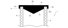
- FIG. 13 shows still another embodiment of the ceiling part 5.
- the ceiling 5 and the lid 31 (the top plate 31 and the side wall 32) are integrally formed by resin molding.
- the ceiling 5 and the lid 31 may be manufactured in advance as a single molded product, and the molded product may be fixed to the filter body 2 with a fixing member, resin, or the like, or directly to the filter body 2.
- the ceiling 5 and the lid 31 may be resin-molded.
- the lower surface 5g of the ceiling portion 5 is below the position A of the lower end 32a of the outer wall 32.
- the lower surface 5g of the ceiling portion 5 has the same shape as the lower surface 5b of FIG. 6, but the lower surface 5g may have the same shape as the lower surfaces 5c to 5e of FIGS. 7 to 9. ..
- FIG. 14 shows still another embodiment of the ceiling part 5.
- a part of the top plate 31 of the lid body 3 also serves as the ceiling portion 5.
- the lid 3 may be made of metal or resin.
- the lower surface 5h of the ceiling portion 5 is a conical, pyramidal, or roof-shaped protruding surface similar to the lower surface 5b of FIG. 6, and is located below the position A of the lower end 32a of the side wall 32.
- the shape of the lower surface 5h may be the same as the respective lower surfaces 5c to 5e of FIGS. 7 to 9.
- FIGS. 15 to 19 As means for preventing air accumulation in the inner space of the filter 1, some means other than the above-described embodiment of the present invention are conceivable. They are shown in FIGS. 15 to 19 as reference examples.
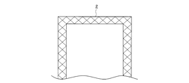
- the upper opening 21 and the lid 3 of FIG. 1 are not provided on the upper part of the filter main body 2, and the filter main body 2 is integrally formed in a bottomed tubular shape, leaving the lower opening 22 of FIG. Has been done. According to this, at the time of water injection at the time of wet down, the air in the internal space can escape through the upper surface of the filter main body 2, so that it is possible to avoid the occurrence of air traps in the internal space.
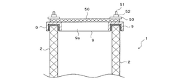
- a flange 9 having an opening 9a is provided on the upper part of the filter body 2 instead of the lid body 3 of FIG.
- a filter plate 50 made of only a filter material is attached to the flange 9 by stud bolts 51, nuts 52, a holding plate 53, and the like.
- the opening 9 a of the flange 9 is covered with the filter plate 50.
- FIG. 17 is a modified example of FIG. 16, in which another flange 54 is added, and the filter plate 50 is attached to this flange 54 with bolts 55, nuts 56, holding plates 57, and the like.
- the top plate 31 of the lid body 3 is formed in a conical shape protruding upward, and a syringe filter (commonly known as a coma filter) 60 is attached to a hole 31g provided at the apex position thereof. ..
- a syringe filter commonly known as a coma filter
- the air in the internal space of the filter body 2 can be released through the syringe filter 60 when water is injected during wet down, so that it is possible to avoid the occurrence of air traps in the internal space. ..
- a hole 31h for venting air is provided in a part of the top plate 31 of the lid 3.
- the hole 31h is provided between the inner cylinder 27 and the outer cylinder 28 at a position corresponding to the secondary space 2s (outside) of the pleated filter medium 26.
- This hole 31h may be provided at a plurality of locations.
- the primary side space 2p (inside) of the pleated filter medium 26 is soiled with dust, the secondary space 2s through which the filtered air flow flows is not soiled with dust. Therefore, an air vent hole 31h is provided here. But there is no worry of pollution. With such a structure, the air in the internal space of the filter body 2 can be released through the holes 31h during the water injection during the wet down, so that it is possible to avoid the occurrence of air traps in the internal space.
- the cylindrical filter main body 2 has been described as an example, but the filter main body 2 may have a rectangular tube shape.
- the HEPA filter is given as an example of the filter 1, but the present invention is also applicable to a ULPA filter (Ultra Low Penetration Air Filter) having higher performance than this and other general filters. It can be applied.
- the air flow gas is taken as an example of the fluid to be filtered, but the present invention can also be applied to an apparatus for filtering liquid or vapor.
- the present invention can be used in places where it is necessary to take precautions against exposure, such as pharmaceutical factories and agrochemical factories that handle highly pharmacologically active substances.
Landscapes
- Chemical & Material Sciences (AREA)
- Chemical Kinetics & Catalysis (AREA)
- Physics & Mathematics (AREA)
- Geometry (AREA)
- Health & Medical Sciences (AREA)
- Engineering & Computer Science (AREA)
- Environmental & Geological Engineering (AREA)
- Toxicology (AREA)
- Filtering Of Dispersed Particles In Gases (AREA)
Abstract
Ce filtre (1) comporte : un corps de filtre creux (2); et un corps de couvercle (3) fixé sur une partie supérieure du corps de filtre (2). Le corps de couvercle (3) comporte : une plaque supérieure (31) pour recouvrir une ouverture supérieure (21) du corps de filtre (2); et une paroi latérale (32) montée sur la partie supérieure du corps de filtre (2). L'extrémité inférieure (32a) de la paroi latérale (32) est positionnée au-dessous de l'extrémité supérieure (2a) du corps de filtre (2). L'ouverture supérieure (21) du corps de filtre (2) est pourvue d'une section de plafond (5) qui peut être en contact avec un liquide injecté dans le corps de filtre (2), et la surface inférieure (5a) de la section de plafond (5) est positionnée à une position (A) de l'extrémité inférieure (32a) de la paroi latérale (32) ou à une position en dessous.
Priority Applications (2)
| Application Number | Priority Date | Filing Date | Title |
|---|---|---|---|
| JP2020559880A JP7426042B2 (ja) | 2018-12-14 | 2019-11-18 | フィルタ、フィルタ装置 |
| EP19895064.4A EP3895782B1 (fr) | 2018-12-14 | 2019-11-18 | Dispositif de filtrage et filtre |
Applications Claiming Priority (2)
| Application Number | Priority Date | Filing Date | Title |
|---|---|---|---|
| JP2018-234045 | 2018-12-14 | ||
| JP2018234045 | 2018-12-14 |
Publications (1)
| Publication Number | Publication Date |
|---|---|
| WO2020121744A1 true WO2020121744A1 (fr) | 2020-06-18 |
Family
ID=71076856
Family Applications (1)
| Application Number | Title | Priority Date | Filing Date |
|---|---|---|---|
| PCT/JP2019/045130 Ceased WO2020121744A1 (fr) | 2018-12-14 | 2019-11-18 | Dispositif de filtrage et filtre |
Country Status (3)
| Country | Link |
|---|---|
| EP (1) | EP3895782B1 (fr) |
| JP (1) | JP7426042B2 (fr) |
| WO (1) | WO2020121744A1 (fr) |
Cited By (2)
| Publication number | Priority date | Publication date | Assignee | Title |
|---|---|---|---|---|
| JP2022076548A (ja) * | 2020-11-10 | 2022-05-20 | 和興フィルタテクノロジー株式会社 | オイル分離装置及びオイル分離装置の製造方法 |
| JP2022095140A (ja) * | 2020-12-16 | 2022-06-28 | 和興フィルタテクノロジー株式会社 | オイル分離装置 |
Citations (9)
| Publication number | Priority date | Publication date | Assignee | Title |
|---|---|---|---|---|
| JPS52130068A (en) * | 1976-04-23 | 1977-11-01 | Whatman Reeve Angel Ltd | Filter tube* filter tube manufacturing method and flowing fluid filtrating method |
| JPS60153902A (ja) * | 1984-01-21 | 1985-08-13 | Kurabo Ind Ltd | カプセル型フイルタ−とその製法 |
| JP2000225182A (ja) * | 1999-02-09 | 2000-08-15 | J Seven:Kk | 医療器具用ガスフィルター |
| JP2003033602A (ja) | 2001-07-25 | 2003-02-04 | Ricoh Elemex Corp | 油水分離装置 |
| JP2010051852A (ja) | 2008-08-26 | 2010-03-11 | Nippon Muki Co Ltd | 空気浄化装置及び空気浄化装置のフィルタ交換方法 |
| JP2016135461A (ja) | 2015-01-23 | 2016-07-28 | 三菱電機株式会社 | 円筒型フィルター及びその製造方法 |
| JP2017154071A (ja) | 2016-03-01 | 2017-09-07 | Smc株式会社 | フィルタエレメント |
| JP2018115977A (ja) | 2017-01-19 | 2018-07-26 | 浜松ホトニクス株式会社 | 観察装置及び観察方法 |
| WO2019244745A1 (fr) * | 2018-06-19 | 2019-12-26 | ホーコス株式会社 | Procédé de remplacement de filtre, dispositif de filtrage, système d'humidification automatique |
Family Cites Families (6)
| Publication number | Priority date | Publication date | Assignee | Title |
|---|---|---|---|---|
| JPS6045306B2 (ja) * | 1978-01-31 | 1985-10-08 | ヤマハ発動機株式会社 | エアクリ−ナ |
| DE4203864C2 (de) * | 1992-02-11 | 1993-12-02 | Deere & Co | Positioniereinrichtung für Luftfilter |
| US5853439A (en) | 1997-06-27 | 1998-12-29 | Donaldson Company, Inc. | Aerosol separator and method |
| JP4674026B2 (ja) * | 1999-11-23 | 2011-04-20 | ポール・コーポレーション | 導電性フィルタカートリッジ |
| ITBO20040063A1 (it) * | 2004-02-12 | 2004-05-12 | Bmc Srl | Dispositivo di filtraggio per l'aria a bassa resistenza |
| DE202013011866U1 (de) * | 2013-09-02 | 2014-12-03 | Mann+Hummel Gmbh | Filterelement und Filtersystem mit einem Filterelement |
-
2019
- 2019-11-18 WO PCT/JP2019/045130 patent/WO2020121744A1/fr not_active Ceased
- 2019-11-18 JP JP2020559880A patent/JP7426042B2/ja active Active
- 2019-11-18 EP EP19895064.4A patent/EP3895782B1/fr active Active
Patent Citations (9)
| Publication number | Priority date | Publication date | Assignee | Title |
|---|---|---|---|---|
| JPS52130068A (en) * | 1976-04-23 | 1977-11-01 | Whatman Reeve Angel Ltd | Filter tube* filter tube manufacturing method and flowing fluid filtrating method |
| JPS60153902A (ja) * | 1984-01-21 | 1985-08-13 | Kurabo Ind Ltd | カプセル型フイルタ−とその製法 |
| JP2000225182A (ja) * | 1999-02-09 | 2000-08-15 | J Seven:Kk | 医療器具用ガスフィルター |
| JP2003033602A (ja) | 2001-07-25 | 2003-02-04 | Ricoh Elemex Corp | 油水分離装置 |
| JP2010051852A (ja) | 2008-08-26 | 2010-03-11 | Nippon Muki Co Ltd | 空気浄化装置及び空気浄化装置のフィルタ交換方法 |
| JP2016135461A (ja) | 2015-01-23 | 2016-07-28 | 三菱電機株式会社 | 円筒型フィルター及びその製造方法 |
| JP2017154071A (ja) | 2016-03-01 | 2017-09-07 | Smc株式会社 | フィルタエレメント |
| JP2018115977A (ja) | 2017-01-19 | 2018-07-26 | 浜松ホトニクス株式会社 | 観察装置及び観察方法 |
| WO2019244745A1 (fr) * | 2018-06-19 | 2019-12-26 | ホーコス株式会社 | Procédé de remplacement de filtre, dispositif de filtrage, système d'humidification automatique |
Cited By (4)
| Publication number | Priority date | Publication date | Assignee | Title |
|---|---|---|---|---|
| JP2022076548A (ja) * | 2020-11-10 | 2022-05-20 | 和興フィルタテクノロジー株式会社 | オイル分離装置及びオイル分離装置の製造方法 |
| JP7451380B2 (ja) | 2020-11-10 | 2024-03-18 | 和興フィルタテクノロジー株式会社 | オイル分離装置及びオイル分離装置の製造方法 |
| JP2022095140A (ja) * | 2020-12-16 | 2022-06-28 | 和興フィルタテクノロジー株式会社 | オイル分離装置 |
| JP7451390B2 (ja) | 2020-12-16 | 2024-03-18 | 和興フィルタテクノロジー株式会社 | オイル分離装置 |
Also Published As
| Publication number | Publication date |
|---|---|
| EP3895782A1 (fr) | 2021-10-20 |
| JP7426042B2 (ja) | 2024-02-01 |
| EP3895782B1 (fr) | 2023-09-06 |
| JPWO2020121744A1 (ja) | 2021-10-28 |
| EP3895782A4 (fr) | 2022-06-29 |
Similar Documents
| Publication | Publication Date | Title |
|---|---|---|
| JP5840628B2 (ja) | エアドライヤカートリッジ及びエアドライヤカートリッジを運転する方法 | |
| EP2621601B1 (fr) | Système de filtre à fluide | |
| US6136076A (en) | Air/oil separator with molded top sealing flange | |
| US4572725A (en) | Air dryer device | |
| US20130001152A1 (en) | Filter device | |
| JP7426042B2 (ja) | フィルタ、フィルタ装置 | |
| JP2014505822A (ja) | 燃料フィルタ | |
| JP2011504135A (ja) | 流体フィルタシステム | |
| CN102481498A (zh) | 过滤器 | |
| RU2562892C2 (ru) | Дыхательное устройство крышки горловины топливного бака | |
| KR101773021B1 (ko) | 복합 사이클론 집진기 | |
| KR101666704B1 (ko) | 집진기 | |
| KR100614894B1 (ko) | 정수 카트리지 | |
| US7213622B2 (en) | Venting device, particularly for fluid-storing reservoirs such as tanks | |
| JP7503784B2 (ja) | 集塵装置、汚染物の回収方法 | |
| CN117883848A (zh) | 软囊式过滤器 | |
| KR20190067248A (ko) | 공기 건조기 카트리지 | |
| KR20060027568A (ko) | 가습기용 필터장치 | |
| US12226722B2 (en) | Fluid filter anti-prefill device | |
| JP2603456Y2 (ja) | 分離装置 | |
| JPH1027739A5 (fr) | ||
| US9956513B2 (en) | Air cleaner casing, air cleaner, and method for manufacturing air cleaner casing | |
| JP2591367Y2 (ja) | ロングライフフィルタ | |
| KR20060101886A (ko) | 오일휠터 | |
| JPS6333411B2 (fr) |
Legal Events
| Date | Code | Title | Description |
|---|---|---|---|
| 121 | Ep: the epo has been informed by wipo that ep was designated in this application |
Ref document number: 19895064 Country of ref document: EP Kind code of ref document: A1 |
|
| ENP | Entry into the national phase |
Ref document number: 2020559880 Country of ref document: JP Kind code of ref document: A |
|
| NENP | Non-entry into the national phase |
Ref country code: DE |
|
| ENP | Entry into the national phase |
Ref document number: 2019895064 Country of ref document: EP Effective date: 20210714 |