WO2020121765A1 - 搬送車 - Google Patents
搬送車 Download PDFInfo
- Publication number
- WO2020121765A1 WO2020121765A1 PCT/JP2019/045448 JP2019045448W WO2020121765A1 WO 2020121765 A1 WO2020121765 A1 WO 2020121765A1 JP 2019045448 W JP2019045448 W JP 2019045448W WO 2020121765 A1 WO2020121765 A1 WO 2020121765A1
- Authority
- WO
- WIPO (PCT)
- Prior art keywords
- amount
- unit
- drive unit
- elevating
- sensor
- Prior art date
- Legal status (The legal status is an assumption and is not a legal conclusion. Google has not performed a legal analysis and makes no representation as to the accuracy of the status listed.)
- Ceased
Links
Images


Classifications
-
- H—ELECTRICITY
- H10—SEMICONDUCTOR DEVICES; ELECTRIC SOLID-STATE DEVICES NOT OTHERWISE PROVIDED FOR
- H10P—GENERIC PROCESSES OR APPARATUS FOR THE MANUFACTURE OR TREATMENT OF DEVICES COVERED BY CLASS H10
- H10P72/00—Handling or holding of wafers, substrates or devices during manufacture or treatment thereof
- H10P72/30—Handling or holding of wafers, substrates or devices during manufacture or treatment thereof for conveying, e.g. between different workstations
- H10P72/32—Handling or holding of wafers, substrates or devices during manufacture or treatment thereof for conveying, e.g. between different workstations between different workstations
- H10P72/3214—Handling or holding of wafers, substrates or devices during manufacture or treatment thereof for conveying, e.g. between different workstations between different workstations by means of a cart or a vehicle
-
- H—ELECTRICITY
- H10—SEMICONDUCTOR DEVICES; ELECTRIC SOLID-STATE DEVICES NOT OTHERWISE PROVIDED FOR
- H10P—GENERIC PROCESSES OR APPARATUS FOR THE MANUFACTURE OR TREATMENT OF DEVICES COVERED BY CLASS H10
- H10P72/00—Handling or holding of wafers, substrates or devices during manufacture or treatment thereof
- H10P72/30—Handling or holding of wafers, substrates or devices during manufacture or treatment thereof for conveying, e.g. between different workstations
- H10P72/32—Handling or holding of wafers, substrates or devices during manufacture or treatment thereof for conveying, e.g. between different workstations between different workstations
- H10P72/3221—Overhead conveying
-
- B—PERFORMING OPERATIONS; TRANSPORTING
- B61—RAILWAYS
- B61B—RAILWAY SYSTEMS; EQUIPMENT THEREFOR NOT OTHERWISE PROVIDED FOR
- B61B3/00—Elevated railway systems with suspended vehicles
-
- B—PERFORMING OPERATIONS; TRANSPORTING
- B65—CONVEYING; PACKING; STORING; HANDLING THIN OR FILAMENTARY MATERIAL
- B65G—TRANSPORT OR STORAGE DEVICES, e.g. CONVEYORS FOR LOADING OR TIPPING, SHOP CONVEYOR SYSTEMS OR PNEUMATIC TUBE CONVEYORS
- B65G1/00—Storing articles, individually or in orderly arrangement, in warehouses or magazines
- B65G1/02—Storage devices
- B65G1/04—Storage devices mechanical
- B65G1/0457—Storage devices mechanical with suspended load carriers
-
- H—ELECTRICITY
- H10—SEMICONDUCTOR DEVICES; ELECTRIC SOLID-STATE DEVICES NOT OTHERWISE PROVIDED FOR
- H10P—GENERIC PROCESSES OR APPARATUS FOR THE MANUFACTURE OR TREATMENT OF DEVICES COVERED BY CLASS H10
- H10P72/00—Handling or holding of wafers, substrates or devices during manufacture or treatment thereof
- H10P72/06—Apparatus for monitoring, sorting, marking, testing or measuring
- H10P72/0606—Position monitoring, e.g. misposition detection or presence detection
-
- H—ELECTRICITY
- H10—SEMICONDUCTOR DEVICES; ELECTRIC SOLID-STATE DEVICES NOT OTHERWISE PROVIDED FOR
- H10P—GENERIC PROCESSES OR APPARATUS FOR THE MANUFACTURE OR TREATMENT OF DEVICES COVERED BY CLASS H10
- H10P72/00—Handling or holding of wafers, substrates or devices during manufacture or treatment thereof
- H10P72/30—Handling or holding of wafers, substrates or devices during manufacture or treatment thereof for conveying, e.g. between different workstations
- H10P72/32—Handling or holding of wafers, substrates or devices during manufacture or treatment thereof for conveying, e.g. between different workstations between different workstations
- H10P72/3202—Mechanical details, e.g. rollers or belts
-
- H—ELECTRICITY
- H10—SEMICONDUCTOR DEVICES; ELECTRIC SOLID-STATE DEVICES NOT OTHERWISE PROVIDED FOR
- H10P—GENERIC PROCESSES OR APPARATUS FOR THE MANUFACTURE OR TREATMENT OF DEVICES COVERED BY CLASS H10
- H10P72/00—Handling or holding of wafers, substrates or devices during manufacture or treatment thereof
- H10P72/30—Handling or holding of wafers, substrates or devices during manufacture or treatment thereof for conveying, e.g. between different workstations
- H10P72/32—Handling or holding of wafers, substrates or devices during manufacture or treatment thereof for conveying, e.g. between different workstations between different workstations
- H10P72/3208—Changing the direction of the conveying path
-
- H—ELECTRICITY
- H10—SEMICONDUCTOR DEVICES; ELECTRIC SOLID-STATE DEVICES NOT OTHERWISE PROVIDED FOR
- H10P—GENERIC PROCESSES OR APPARATUS FOR THE MANUFACTURE OR TREATMENT OF DEVICES COVERED BY CLASS H10
- H10P72/00—Handling or holding of wafers, substrates or devices during manufacture or treatment thereof
- H10P72/30—Handling or holding of wafers, substrates or devices during manufacture or treatment thereof for conveying, e.g. between different workstations
- H10P72/32—Handling or holding of wafers, substrates or devices during manufacture or treatment thereof for conveying, e.g. between different workstations between different workstations
- H10P72/3218—Conveying cassettes, containers or carriers
-
- H—ELECTRICITY
- H10—SEMICONDUCTOR DEVICES; ELECTRIC SOLID-STATE DEVICES NOT OTHERWISE PROVIDED FOR
- H10P—GENERIC PROCESSES OR APPARATUS FOR THE MANUFACTURE OR TREATMENT OF DEVICES COVERED BY CLASS H10
- H10P72/00—Handling or holding of wafers, substrates or devices during manufacture or treatment thereof
- H10P72/30—Handling or holding of wafers, substrates or devices during manufacture or treatment thereof for conveying, e.g. between different workstations
- H10P72/32—Handling or holding of wafers, substrates or devices during manufacture or treatment thereof for conveying, e.g. between different workstations between different workstations
- H10P72/3222—Loading to or unloading from a conveyor
-
- H—ELECTRICITY
- H10—SEMICONDUCTOR DEVICES; ELECTRIC SOLID-STATE DEVICES NOT OTHERWISE PROVIDED FOR
- H10P—GENERIC PROCESSES OR APPARATUS FOR THE MANUFACTURE OR TREATMENT OF DEVICES COVERED BY CLASS H10
- H10P72/00—Handling or holding of wafers, substrates or devices during manufacture or treatment thereof
- H10P72/50—Handling or holding of wafers, substrates or devices during manufacture or treatment thereof for positioning, orientation or alignment
- H10P72/53—Handling or holding of wafers, substrates or devices during manufacture or treatment thereof for positioning, orientation or alignment using optical controlling means
-
- B—PERFORMING OPERATIONS; TRANSPORTING
- B65—CONVEYING; PACKING; STORING; HANDLING THIN OR FILAMENTARY MATERIAL
- B65G—TRANSPORT OR STORAGE DEVICES, e.g. CONVEYORS FOR LOADING OR TIPPING, SHOP CONVEYOR SYSTEMS OR PNEUMATIC TUBE CONVEYORS
- B65G2201/00—Indexing codes relating to handling devices, e.g. conveyors, characterised by the type of product or load being conveyed or handled
- B65G2201/02—Articles
- B65G2201/0297—Wafer cassette
Definitions
- the present invention relates to a carrier vehicle.
- a carrier vehicle running along a ceiling or a rail laid near the ceiling is used. It is used.
- the transport vehicle includes a traveling unit that travels on a track, a main body unit that is moved by traveling of the traveling unit, an elevating table that can be elevated with respect to the main body unit, and an elevating drive unit that elevates the elevating platform, Further, the horizontal drive mechanism is provided which causes the lifting drive unit to project laterally in the traveling direction with respect to the main body unit.
- This transport vehicle stops at the article transfer position provided in the factory, and depending on the transfer destination, the elevating drive unit is raised and lowered by the elevating drive unit while the elevating drive unit is raised by the horizontal ejection mechanism.
- An article is delivered by gripping or opening the article by a holding unit provided.
- the sideways-out mechanism is used for sideways-out, the sideways-out mechanism is deflected due to the weight of the lifting/lowering drive unit and the articles, and the deflection causes the articles to move to the specified transfer position. It may be impossible to transfer.
- a carrier vehicle that includes a sensor that emits a detection wave downward to the lifting drive unit.
- a sensor that emits a detection wave downward to the lifting drive unit.
- Patent No. 56364949 International Publication No. 2017/199593
- the amount of deflection that occurs in the sideways mechanism changes depending on the sideways amount of the elevating and lowering drive section by the sideways mechanism.
- the data obtained in the transport vehicle described in Patent Document 1 is a fixed value set when, for example, the elevating drive unit is most laterally extended by the horizontal ejection mechanism. Therefore, in the transport vehicle described in Patent Document 1, when the amount of sideways movement of the elevating and lowering drive unit by the sideways-out mechanism changes, the deflection amount of the sideways-out mechanism changes even if the sideways-out amount is adjusted. Even if the article (elevation platform) is lowered, it may be displaced from the transfer position, and the article may not be delivered to the transfer destination accurately.
- the orientation of the sensor provided in the lifting drive unit also changes depending on the amount of lateral movement of the lifting drive unit by the sideways mechanism. Furthermore, if the descending amount of the lifting table increases with the orientation of the sensor changing, for example, the detection wave from the sensor deviates from the index plate provided on the lifting table, and the detection wave is emitted from the target irradiation destination. There is a problem that it will come off and it will not be possible to perform appropriate detection.
- the article when a sideways-out mechanism is used to sideways-out, by adjusting the sideways-out amount or the orientation of the sensor, the article can be delivered to the transfer destination accurately, or the sensor can be appropriately operated.
- the purpose is to provide a simple transport vehicle.
- a transport vehicle includes a traveling unit that travels on a track, a main body unit that is connected to the traveling unit and moves by traveling of the traveling unit, and a holding unit that holds an article,
- An elevating table that can be raised and lowered, an elevating drive section that elevates and lowers the elevating table by unwinding and winding up a flexible suspension member, and a lateral projection that laterally projects the elevating drive section in a cantilevered state.
- the horizontal movement when delivering or receiving the article to the transfer destination.
- an adjustment unit that performs one or both of the adjustment of the amount and the adjustment of the orientation of the sensor included in the elevation drive unit.
- the sensor may irradiate a detection wave having directivity toward a predetermined position below, and the adjustment unit may adjust the orientation of the sensor so as to correct the deviation of the irradiation direction of the detection wave.
- the sensor may include an actuator for changing the irradiation direction of the detection wave, and the adjustment unit may correct the deviation in the irradiation direction of the detection wave by driving the actuator.
- the main body unit includes a storage unit that stores a data table regarding the amount of lateral movement of the elevating and lowering drive unit by the lateral ejection mechanism and the amount of descending to the transfer destination for each of the plurality of transfer destinations that transfer the article.
- the adjusting unit acquires information regarding the transfer destination of the article from the data table stored in the storage unit, adjusts the sideways amount based on the information, and adjusts the orientation of the sensor provided in the lifting drive unit, Either one or both may be performed.
- the storage unit stores in advance the machine difference of the own vehicle that is unique to each transport vehicle, and the adjustment unit adjusts the sideways amount and raises and lowers the drive including the machine difference stored in the storage unit. Either or both of the adjustment of the orientation of the sensor provided in the unit may be performed.
- the adjusting unit adjusts the horizontal projection amount and the elevating and lowering driving unit when the horizontal projection amount indicated by the data table is the first specific value and the downward movement amount indicated by the data table is less than the first threshold value. If the descending amount indicated by the data table is equal to or greater than the first threshold value without adjusting both the orientations of the sensors provided in the Either or both may be performed.
- the adjusting unit adjusts the lateral projection amount and raises and lowers the driving unit when the lateral projection amount indicated by the data table is less than the second threshold value when the downward motion amount indicated by the data table is the second specific value. If both of the adjustments of the orientation of the sensor provided in the above are not performed and the amount of sideways indicated by the data table is equal to or greater than the second threshold, Either one or both may be performed.
- the transport vehicle According to the above-mentioned transport vehicle, according to the amount of lateral movement of the elevating and lowering drive unit by the lateral ejection mechanism and the amount of elevating and lowering of the elevating table by the elevating and lowering drive unit, there are a case of delivering an article to a transfer destination and a case of receiving an article.
- the amount of horizontal ejection in step 1 the article can be accurately delivered to the destination.
- the orientation of the sensor provided in the elevator drive unit according to the amount of sideways-out and the amount of lowering of the elevator, it is possible to orient the sensor in the target direction, and to operate the sensor appropriately. It is possible to suppress erroneous detection while ensuring.
- the sideways amount is adjusted depending on whether the product is delivered to the transfer destination or received, so that the product can be accurately transferred to the transfer destination by considering the effect of deflection due to the weight of the product. Can be handed over to.
- the sensor irradiates a detection wave having directivity toward a predetermined position below and the adjustment unit adjusts the sensor direction so as to correct the deviation of the detection wave in the irradiation direction
- the sensor irradiates the detection wave. It is possible to accurately adjust the direction of the detected wave to be detected.
- the sensor includes an actuator for changing the irradiation direction of the detection wave, and the adjusting unit drives the actuator to correct the deviation in the irradiation direction of the detection wave
- the detection wave is driven by driving the actuator. The direction of can be adjusted with high precision.
- the main body unit includes a storage unit that stores a data table regarding the amount of lateral movement of the elevating and lowering drive unit by the lateral ejection mechanism and the amount of descending to the transfer destination for each of the plurality of transfer destinations that deliver and receive the article.
- the adjustment unit acquires information about the transfer destination of the article from the data table stored in the storage unit, and adjusts the sideways amount or adjusts the orientation of the sensor included in the lifting drive unit. Alternatively, in a configuration in which both of them are performed, it is possible to quickly and accurately adjust the amount of horizontal projection and the orientation of the sensor by reading the data table stored in the storage unit.
- the storage unit stores in advance the machine difference of the own vehicle that is unique to each transport vehicle, and the adjustment unit adjusts the sideways amount and raises and lowers the drive including the machine difference stored in the storage unit.
- the sideways amount is adjusted and the orientation of the sensor is adjusted in consideration of the influence of the machine difference occurring for each transport vehicle.
- the goods can be accurately delivered to the transfer destination by each carrier.
- the adjusting unit adjusts the horizontal amount of projection and the elevating/lowering drive unit. If the descending amount indicated by the data table is equal to or greater than the first threshold value without adjusting both the orientations of the sensors provided in the In a configuration in which one or both of them are performed, the presence or absence of adjustment can be switched according to the amount of lowering.
- the adjusting unit adjusts the amount of lateral protrusion and the elevating/lowering drive unit if the amount of lateral protrusion indicated by the data table is less than the second threshold value. If both of the adjustments of the orientation of the sensor provided in the above are not performed and the amount of sideways indicated by the data table is equal to or greater than the second threshold, In a configuration in which either one or both are performed, the presence/absence of adjustment can be switched according to the amount of horizontal projection.
- the direction indicated by the arrow in the drawing is the + direction, and the opposite direction is the ⁇ direction.
- the rotation direction around the X axis is represented as the ⁇ X direction
- the rotation direction around the Y axis is represented as the ⁇ Y direction
- the rotation direction around the Z axis is represented as the ⁇ Z direction.
- FIG. 1 is a diagram showing an example of a carrier vehicle according to the present embodiment.
- a transfer system including a transfer vehicle 100 is provided in a processing room PR such as a clean room.
- a semiconductor processing device (not shown) or the like is arranged on the floor in the processing chamber PR.
- a rail R which is a track for guiding the transport vehicle 100, is provided on the ceiling of the processing chamber PR.
- the rail R is configured to include a traveling rail and a power feeding rail.
- the carrier 100 runs along the rail R in, for example, the +Y direction.
- the transport vehicle 100 delivers the article FP to the transfer destination S.
- the transfer destination S is, for example, a load port of the processing device.
- the carrier vehicle 100 includes a traveling drive unit (traveling unit) 10, a connecting unit 30, a main body unit 40, and a control unit 80.
- the drive of each unit of the transport vehicle 100 is controlled by the control unit 80.
- the control unit 80 is provided, for example, in the main body unit 40, but is not limited to this configuration and may be provided outside the main body unit 40.
- the traveling drive unit 10 is arranged inside the rail R, and includes a plurality of rollers 11 that come into contact with the inner surface (traveling surface) of the rail R, and a drive device 12 that rotates the plurality of rollers 11. ..
- the transport vehicle 100 receives power via a non-contact power supply line provided on a power feed rail (not shown) along the rail R, and supplies power to a drive unit such as the traveling drive unit 10 provided on the transport vehicle 100 (not shown). Equipped with.
- the connecting portion 30 is attached to the lower side ( ⁇ Z side) of the traveling drive portion 10 and connects the traveling drive portion 10 and the main body portion 40.
- the main body 40 includes a transfer device 41.
- the transfer device 41 includes an elevating table 42, an elevating/lowering drive unit 43, a sensor 44, a sideways-out mechanism 45, and a correction mechanism 46.
- the body portion 40 is connected to the traveling drive unit 10 via the connecting portion 30.
- the main body 40 moves along the rail R integrally with the traveling drive unit 10.
- the lift table 42 can move up and down with respect to the main body 40 (movable in the Z direction).
- the elevating table 42 has a gripper 42a as a holding unit that holds the article FP.
- the article FP is, for example, a container (FOUP) containing a semiconductor wafer, a reticle pod containing a reticle, or the like.
- the gripper 42a is capable of gripping or releasing the flange FPa provided on the top portion (the surface on the +Z side) of the article FP.
- the lift drive unit 43 moves the lift table 42 up and down (moves in the Z direction).
- the elevating/lowering drive unit 43 suspends the elevating/lowering table 42 via a plurality of (for example, four) flexible belts (hanging members) 43a, for example.
- the elevating/lowering drive unit 43 elevates and lowers the elevating table 42 by feeding or winding the belt 43a.
- the sensor 44 is provided in the lift drive unit 43.
- the sensor 44 includes a shake detection sensor (swing sensor) 47 and a look-down sensor 48.
- the shake detection sensor 47 and the look-down sensor 48 irradiate a detection wave having directivity, such as a laser beam, toward a detection target region below the elevation drive unit 43.
- a configuration in which the shake detection sensor 47 and the look-down sensor 48 irradiate a laser beam as a detection wave will be described as an example.
- the shake detection sensor 47 and the look-down sensor 48 may be configured to irradiate other detection waves having directivity such as ultrasonic waves in addition to the laser light.
- the shake detection sensor 47 emits the laser light L1 toward the reflection plate 49 provided on the upper surface (the surface on the +Z side) of the lift table 42.
- the shake detection sensor 47 irradiates the reflection plate 49 with the laser light L1 when moving the elevator 42 up and down, and detects the shake of the elevator 42 from the reflected light.
- the control unit 80 determines that the shake (amplitude) is within the normal range while the laser light L1 from the shake detection sensor 47 is hitting the reflector 49, and the shake is within the normal range when the laser light L1 deviates from the reflector 49. Is deviated (the amplitude is increased and exceeds the allowable limit), and the elevating/lowering of the elevating table 42 is stopped.
- the look-down sensor 48 irradiates the laser light L2 toward the vicinity of the descending destination of the elevating table 42.
- the look-down sensor 48 irradiates the laser beam L2 and detects from the reflected light whether or not a foreign substance is present in the vicinity of the transfer destination S, which is the descending destination of the elevating table 42. For example, it is detected whether or not an object (obstacle) such as a worker exists in the area on the passage side of the transfer destination S.
- the control unit 80 stops the elevation of the elevator 42.
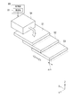
- FIG. 2 is a perspective view showing an example of the side-out mechanism 45.
- the sideways-out mechanism 45 projects the elevation drive unit 43 laterally (X direction) in a cantilevered state.
- the sideways-out mechanism 45 includes an upper stage portion 51, a middle stage portion 52, a lower stage portion 53, and a drive device 54.
- the upper portion 51 is provided on the upper side of the main body portion 40.
- the upper portion 51 may be fixed to the main body portion 40, or may be movable in the +X direction or the ⁇ X direction, which is the side portion of the main body portion 40, by a guide (not shown).
- the middle section 52 is attached to the lower side of the upper section 51.
- the middle section 52 moves in the +X direction or the ⁇ X direction with respect to the upper section 51 by a guide (not shown).
- the lower step portion 53 is attached to the lower side of the middle step portion 52.
- the lower part 53 moves in the +X direction or the ⁇ X direction with respect to the middle part 52.
- the upper stage portion 51, the middle stage portion 52, and the lower stage portion 53 are moved by the drive device 54.
- the drive unit 54 performs a horizontal ejection operation under the control of the control unit 80.
- a linear motor, a rotary motor including a ball screw mechanism, or the like is used.
- 1 and 2 show an example in which the upper stage portion 51, the middle stage portion 52, and the lower stage portion 53 move to the ⁇ X side with respect to the main body portion 40, but the present invention is not limited to this example. , And can be moved to the +X side with respect to the main body 40.
- the upper step portion 51, the middle step portion 52, and the lower step portion 53 are not limited to being plate-shaped as shown in the figure, and a rod-shaped member or a frame in which rod-shaped members are combined may be used.
- the drive device 54 causes the upper step portion 51 and the like to be laterally projected so as to have a preset lateral projection amount in the +X direction or the ⁇ X direction according to an instruction from the control unit 80. Further, the drive device 54 functions as a correction mechanism for adjusting the lateral projection amount in the +X direction or the ⁇ X direction.
- a lifting drive unit 43 is attached to the lower surface of the lower stage portion 53.
- a swing drive unit (not shown) capable of swinging the lift drive unit 43 in the ⁇ Z direction with respect to the lower stage portion 53 may be provided.
- a swing drive unit (not shown) capable of swinging the gripper 42a in the ⁇ Z direction with respect to the lift table 42 may be provided.
- the sideways-out mechanism 45 is configured such that the weight of the middle stage portion 52 and the lower stage portion 53, the elevating drive unit 43, and the lift table 42 in the state where the middle stage portion 52 and the lower stage portion 53 are projected to the side ( ⁇ X side) of the main body portion 40.
- the weight of the article FP or the like causes the entire body to bend downward, and the tip side of the lower step portion 53 moves downward.
- the elevating/lowering drive unit 43 is inclined in the ⁇ Y direction due to the inclination of the lower stage portion 53.
- the lift table 42 is positioned vertically below the lift drive unit 43 even when the lift drive unit 43 is tilted in the ⁇ Y direction.
- the correction mechanism 46 corrects the deviation in the irradiation direction of the laser beams L1 and L2 caused by the deflection of the side-out mechanism 45 when the elevation drive unit 43 is projected to the side of the main body section 40 by the side-out mechanism 45.
- the correction mechanism 46 includes a first correction mechanism 60 and a second correction mechanism 70.
- the first correction mechanism 60 corrects the deviation of the shake detection sensor 47 in the irradiation direction of the laser light L1.
- the second correction mechanism 70 corrects the deviation of the look-down sensor 48 in the irradiation direction of the laser light L2.
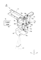
- FIG. 3 is a perspective view showing an example of the first correction mechanism 60.
- the first correction mechanism 60 includes a frame 61, a shaft portion 62, a movable portion 63, a tilt adjusting mechanism 64, a rotation restricting portion 65, and a first correction driving portion 66. doing.
- the frame 61 is formed of a metal plate or the like, and is fixed to the elevating/lowering drive unit 43 with bolts or the like.
- the shaft portion 62 is formed so as to project from the frame 61.
- the shaft portion 62 has a central axis AX1 parallel to the Y direction.
- the movable portion 63 can rotate (swing) about the shaft portion 62 in the ⁇ Y direction with respect to the frame 61.
- the movable portion 63 has a suspension member 63a and a support member 63b.
- the hanging member 63a is formed so as to extend downward from the shaft portion 62, and is supported rotatably in the ⁇ Y direction with respect to the central axis AX1 of the shaft portion 62.
- the support member 63b is rotatable with the hanging member 63a in the ⁇ Y direction about the central axis AX1.
- the support member 63b has an opening as shown in FIG. 3, and supports the shake detection sensor 47 via a sensor fixing member 64a described later.
- the tilt adjusting mechanism 64 adjusts the tilt of the shake detection sensor 47.
- the tilt adjusting mechanism 64 has a sensor fixing member 64a, a screw portion 64b, and a nut 64c.
- the sensor fixing member 64a fixes the shake detection sensor 47 by a predetermined fixing member.
- the sensor fixing member 64a is a U-shaped member when viewed from the Z direction.
- the screw parts 64b are arranged on both sides in the X direction with the shake detection sensor 47 interposed therebetween.
- the screw portions 64b are arranged at both ends of the sensor fixing member 64a.
- the screw portion 64b is screwed to a tap formed on the support member 63b, extends upward (in the +Z direction) from the support member 63b, and has its tip in contact with the lower surface of the sensor fixing member 64a.
- the nut 64c is screwed to the lower end of the screw portion 64b on the lower surface of the support member 63b.
- the distance between the sensor fixing member 64a and the supporting member 63b is individually adjusted, and the inclination of the shake detection sensor 47 in the ⁇ Y direction (the irradiation direction of the laser beam L1) is vertical. It can be adjusted so as to be downward ( ⁇ Z direction).
- the rotation restricting portion 65 defines the rotation range of the movable portion 63 around the central axis AX1 in the ⁇ Y direction.
- the rotation restricting portion 65 has a base portion 65a, a screw portion 65b, and a nut 65c.
- the base portion 65a is fixed to the frame 61.
- the screw portions 65b are arranged on both sides of the shake detection sensor 47 in the support member 63b, sandwiching the shake detection sensor 47 in the X direction.
- the screw portion 65b is arranged so as to penetrate the support member 63b, and is held by the nut 65c in a state of protruding toward the base portion 65a.
- the protruding amount of the screw portion 65b can be adjusted by the screw coupling position with the nut 65c.
- the tip end of the screw portion 65b contacts the base portion 65a to define the rotation range of the movable portion 63.
- the position of the tip of the screw portion 65b is preset according to the angle at which the elevating/lowering drive unit 43 tilts in the ⁇ Y direction.
- the rotation restricting portion 65 is positioned at three points (a position where the screw portion 65b abuts on the base portion 65a on the ⁇ X side, a center position where the screw portion 65b abuts on the base portion 65a on the +X side), It is possible to deal with both sides of the side-out mechanism 45 (side-out in the -X direction or side-out in the +X direction).
- the first correction driving unit 66 applies a driving force in the X direction to the movable unit 63.
- the first correction drive unit 66 has an actuator 66a and a transmission mechanism 66b.
- As the actuator 66a for example, a solenoid or the like is used.
- the transmission mechanism 66b transmits the driving force of the actuator 66a to the support member 63b.
- the transmission mechanism 66b may be configured to include an elastic member.
- the movable portion 63 rotates about the central axis AX1 in the ⁇ Y direction, the posture of the shake detection sensor 47 changes, and the laser light L1 emitted from the shake detection sensor 47 according to the rotational position of the movable portion 63 changes. Irradiation direction changes.
- the amount of protrusion in the X direction by the sideways-out mechanism 45 varies depending on the position of the transfer destination S.
- the inclination of the elevating/lowering drive unit 43 in the ⁇ Y direction varies depending on the amount of protrusion by the side-out mechanism 45. Therefore, in the present embodiment, when the elevating/lowering drive unit 43 is projected by the sideways-out mechanism 45, whether or not the control unit 80 should change the irradiation direction of the laser beam L1 according to the inclination of the elevating/lowering drive unit 43 in the ⁇ Y direction. To judge.
- the first correction drive unit 66 drives the support member 63b by the adjustment unit 81 described later, and the movable unit 63 is rotated as described above.
- the control unit 80 controls the laser beam L1 from the shake detection sensor 47 according to the tilt of the elevation drive unit 43 only by two types of control such that the first correction drive unit 66 drives or does not drive the support member 63b.
- the irradiation direction can be corrected.
- the transmission mechanism 66b is held at a predetermined position by an elastic body such as a spring arranged in the solenoid which is the first correction drive unit 66.
- the movable portion 63 is held at a predetermined position, and the irradiation direction of the laser light L1 from the shake detection sensor 47 is set to face downward.
- FIG. 4 is a perspective view showing an example of the second correction mechanism 70.
- the second correction mechanism 70 includes a frame 71, a shaft portion 72, a movable portion 73, an inclination adjusting mechanism 74, and a second correction driving portion 76.
- the frame 71 is formed of a metal plate or the like, and is fixed to the elevating/lowering drive unit 43 with bolts or the like.
- the frame 71 includes a strip-shaped portion 71a extending downward.
- the shaft portion 72 is formed so as to project from the belt-shaped portion 71a.
- the shaft portion 72 has a central axis AX2 parallel to the Y direction.
- the movable portion 73 rotates about the shaft portion 72 in the ⁇ Y direction with respect to the frame 71.
- the movable portion 73 has a drive piece 73a and an action piece (not shown).
- the drive piece 73a is formed so as to extend from the shaft portion 72 in the ⁇ X direction and bend upward.
- the operating piece (not shown) is arranged on the +X side with respect to the shaft portion 72.
- the drive piece 73a and the action piece can be integrally rotated in the ⁇ Y direction about the central axis AX2.
- the drive piece 73a supports the look-down sensor 48 via a sensor fixing member 74a described later.
- the tilt adjusting mechanism 74 adjusts the tilt of the look-down sensor 48 with respect to the driving piece 73a.
- the tilt adjusting mechanism 74 has a sensor fixing member 74a, a mounting screw 74b, and an adjusting screw 74c.
- the sensor fixing member 74a is attached to the driving piece 73a with a mounting screw 74b.
- the lower end of the sensor fixing member 74a is arranged so as to project below the shaft portion 72.
- the adjusting screw 74c is attached to the lower end of the sensor fixing member 74a.
- the adjustment screw 74c fixes the look-down sensor 48 to the sensor fixing member 74a and adjusts the inclination of the look-down sensor 48 in the ⁇ Y direction with respect to the sensor fixing member 74a.
- FIG. 4 in the present embodiment, when viewed from the +X direction, for example, the ⁇ Y side and +Z side corners of the look-down sensor 48 and the +Y side and ⁇ Z side corners are divided into two parts.
- the adjusting screw 74c is arranged at a position.
- the distance between the look-down sensor 48 and the sensor fixing member 74a is adjusted, and the inclination of the look-down sensor 48 in the ⁇ Y direction (so that the laser beam L2 is irradiated in a predetermined direction). ) Adjustable.
- the tilt adjusting mechanism 74 includes a rotation restricting unit (not shown).
- the rotation restricting portion defines a rotation range of the movable portion 73 about the central axis AX2 in the ⁇ Y direction.
- this rotation restricting portion for example, two screw portions are arranged, and when the movable portion 73 rotates in the ⁇ Y direction about the central axis AX2, the tip of the screw portion abuts the fixed portion to rotate the movable portion 73.
- the rotation restriction unit is set in advance according to the angle at which the elevating/lowering drive unit 43 tilts in the ⁇ Y direction.
- the rotation restricting portion performs positioning at three points (the position where the look-down sensor 48 is tilted toward the ⁇ X side, the center, and the position where the look-down sensor 48 is tilted toward the +X side), so that the lateral movement mechanism 45 is positioned. It is possible to deal with both-sided projection (horizontal projection in the ⁇ X direction or lateral projection in the +X direction).
- the second correction driving unit 76 applies a driving force in the X direction to the movable unit 73.
- the second correction driving unit 76 has an actuator 76a and a transmission mechanism 76b.
- As the actuator 76a for example, a solenoid or the like is used.
- the transmission mechanism 76b transmits the driving force of the actuator 76a to the driving piece 73a.
- the transmission mechanism 76b may be configured to include an elastic member.
- the second correction driving unit 76 drives the driving piece 73a, so that a driving force in the X direction acts on the driving piece 73a.
- the movable portion 73 rotates about the central axis AX2 in the ⁇ Y direction, the posture of the look-down sensor 48 changes, and the laser light L2 emitted from the look-down sensor 48 changes in accordance with the rotational position of the movable portion 73. Irradiation direction changes.
- the amount of protrusion in the X direction by the sideways-out mechanism 45 varies depending on the position of the transfer destination S.
- the inclination of the elevating/lowering drive unit 43 in the ⁇ Y direction varies depending on the amount of protrusion by the side-out mechanism 45. Therefore, in the present embodiment, when the elevating/lowering drive unit 43 is projected by the side-out mechanism 45, whether or not the control unit 80 should change the irradiation direction of the laser beam L2 according to the inclination of the elevating/lowering drive unit 43 in the ⁇ Y direction. To judge.
- the adjustment unit 81 drives the second correction driving unit 76 to rotate the movable unit 73 as described above, and the look-down sensor.
- the irradiation direction of the laser beam L2 emitted from 48 can be corrected.
- the control unit 80 controls the laser beam L2 from the look-down sensor 48 according to the inclination of the elevating/lowering drive unit 43 only by two types of control such that the second correction drive unit 76 drives or does not drive the drive piece 73a.
- the irradiation direction can be corrected.
- the transmission mechanism 76b is held at a predetermined position by an elastic body such as a spring arranged in the solenoid which is the second correction drive unit 76.
- the movable portion 73 is held at a predetermined position, and the irradiation direction of the laser beam L2 from the look-down sensor 48 is set to face the predetermined direction.
- the actuators 66a and 76a described above are not limited to solenoids.
- a ball screw mechanism using an electric motor, a hydraulic or pneumatic cylinder mechanism, a linear motor or the like may be used.
- the control unit 80 comprehensively controls the operation of the carrier vehicle 100.
- the control unit 80 includes an adjustment unit 81 and a storage unit 82.
- the adjustment unit 81 performs at least one of adjustment of the amount of lateral movement of the elevating and lowering drive unit 43 by the lateral ejection mechanism 45 and adjustment of the orientation of the sensor 44 included in the elevating and lowering drive unit 43.
- the adjusting unit 81 performs the above-described adjustment according to the amount of lateral movement of the elevating drive unit 43 by the lateral ejection mechanism 45 and the amount of lowering of the elevating table 42 by the elevating drive unit 43.
- the sideways-out mechanism 45 when the sideways-out mechanism 45 is projected in the lateral direction of the transport vehicle 100, the sideways-out mechanism 45 may be moved out depending on the weight of the side-out mechanism 45 itself, the weight of the elevating/lowering drive unit 43, the weight of the elevating table 42, and the weight of the article FP.
- the mechanism 45 is bent. Due to this deflection, the lift table 42 (article FP) is displaced from directly above the mounting surface at the transfer position at the transfer destination S, and even if the lift table 42 (article FP) is lowered in this state, the transfer is performed.
- the article FP is placed on the placement surface at a position deviated from the placement surface.
- the side-out mechanism corresponding to the weight of the article FP is used. Since the amount of flexure generated in 45 is different, the appropriate lateral projection amount is different in order to arrange the elevating/lowering drive unit 43 immediately above the transfer position. Therefore, in order to correct such a deviation of the elevating and lowering drive unit 43, it is necessary to adjust the laterally extending amount of the elevating and lowering drive unit 43 by the laterally ejecting mechanism 45 in consideration of the bending of the laterally ejecting mechanism 45.
- the adjusting unit 81 adjusts the lateral ejection amount of the elevating drive unit 43 by the lateral ejection mechanism 45 and the lateral ejection amount of the elevating drive unit 43 by the lateral ejection mechanism 45 according to the presence or absence of the article FP.
- the adjusting unit 81 adjusts the drive amount of the drive device 54 to adjust the upper stage portion 51 in the X direction, as shown in FIG.
- the positions of the middle section 52 and the lower section 53 are adjusted. Due to the bending of the side-out mechanism 45, the position of the elevation drive unit 43 in the X direction is shifted to a position closer to the main body unit 40. Therefore, the adjusting unit 81 adjusts the position of at least one of the upper stage unit 51, the middle stage unit 52, and the lower stage unit 53 in the X direction, and adjusts the position of the lift drive unit 43 supported by the lower stage unit 53.
- the adjustment unit 81 adjusts the shake detection sensor 47 and the look-down sensor 48 according to the amount of lateral movement of the elevating drive unit 43 by the lateral ejection mechanism 45 and the amount of lowering of the elevating table 42 by the elevating drive unit 43. ..
- the elevating table 42 is rotated around the ⁇ Y axis when it is laterally extended by the horizontal ejection mechanism 45. As the lift table 42 rotates about the ⁇ Y axis, the shake detection sensor 47 and the look-down sensor 48 also rotate about the ⁇ Y axis.
- the distance between the shake detection sensor 47 and the lift table 42 increases as the descending amount of the lift table 42 increases, so that the shake of the lift table 42 ( Even if the (amplitude) is not so large, the laser beam L1 may deviate from the reflector 49, and the shake detection sensor 47 may erroneously detect that the shake exceeds the allowable limit.
- the look-down sensor 48 even if the rotation about the ⁇ Y axis is small, if the descending amount of the elevating table 42 is large, the distance from the place where an object such as an operator should be detected becomes large, and therefore the look-down sensor 48 is
- the irradiated laser beam L2 may deviate from the above-mentioned location, and for example, the load port or the like, which is the transfer destination S of the article FP, may be erroneously detected as an obstacle. Therefore, when adjusting the shake detection sensor 47, as shown in FIG. 3, the adjusting unit 81 drives the actuator 66a of the first correction driving unit 66 to rotate the irradiation direction of the laser light L1 in the ⁇ Y direction. , The deviation of the irradiation direction is corrected so as to face downward.
- the adjusting unit 81 drives the actuator 76a of the second correction driving unit 76 to rotate the irradiation direction of the laser light L2 in the ⁇ Y direction. , The deviation of the irradiation direction is corrected so as to point in a predetermined direction.
- FIG. 5 is a diagram schematically showing an example of the detection operation by the shake detection sensor 47.
- the shake detection sensor 47 irradiates the reflection plate 49 with the laser light L1 and detects the laser light L1 reflected by the reflection plate 49.
- FIG. 5 illustrates the deviation of the laser light L1 with respect to the reflection plate 49 in the detection operation using the shake detection sensor 47, but the same applies to the look-down sensor 48 with respect to the deviation of the laser light L2 with respect to the detection location. Can be said.
- the shake detection sensor 47 irradiates the reflection plate 49 with the laser light L1 and detects the laser light L1 reflected by the reflection plate 49.
- the control unit 80 detects the variation amount of the optical axis position of the laser light L1 based on the detection result of the shake detection sensor 47.
- FIG. 5 shows the state in which the gripper 42a holds the article FP
- the variation amount of the optical axis position of the laser light L1 is similarly detected even in the state in which the gripper 42a does not hold the article FP.
- the irradiation position of the laser beam L1 on the reflection plate 49 changes due to the bending of the side-out mechanism 45, and also changes depending on the descending amount of the elevating table 42.
- the irradiation position of the laser beam L1 fluctuates in the X direction on the reflection plate 49 as shown by the arrow. Therefore, when the horizontal movement amount of the elevating/lowering drive unit 43 by the horizontal ejection mechanism 45 increases and the lowering amount of the elevating table 42 increases, the irradiation position of the laser light L1 deviates from the reflection plate 49, and the shake detection sensor 47 detects. It cannot be detected.
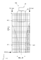
- FIG. 6 is a diagram showing the relationship between the position of the lifting table 42 and the variation amount of the optical axis position when the gripper 42a does not hold the article FP.
- FIG. 7 is a diagram showing the relationship between the position of the lift table 42 and the variation amount of the optical axis position when the gripper 42a holds the article FP. 6 and 7 show experimental results or results obtained by simulation.
- the horizontal axes of FIGS. 6 and 7 show the lateral movement amount of the elevating drive unit 43 by the lateral ejection mechanism 45, and the vertical axes of FIGS. 6 and 7 show the downward movement amount of the elevating table 42 by the elevating drive unit 43.
- the center in the left-right direction indicates 0, and from the center to the maximum value SL1 in the ⁇ X direction (left direction in FIG. 5) and to the maximum value SL2 in the +X direction from the center (right direction in FIG. 5).
- the value of each is shown.
- the maximum value SL1 and the maximum value SL2 are different due to the mechanical reason of the side-out mechanism 45, but the same mechanism may be used.
- the lowering amount of the lifting platform 42 is 0 at the upper end and the maximum value DC at the lower end.
- the lift table 42 is arranged according to the height of the transfer destination S and the laser beam L1 is emitted. It was confirmed that the irradiation position did not come off from the reflection plate 49 of the lift table 42. However, in the areas A1 and A3 where the lift mechanism 43 has a large horizontal projection amount and the vertical lift amount is large. It was confirmed that when the transfer destination S exists, the irradiation position of the laser light L1 deviates from the reflection plate 49.
- the area A1 and the area A3 have different shapes in FIG.
- the transfer destination S exists in the area A2 when the gripper 42a does not hold the article FP, it is not necessary to adjust the irradiation direction of the laser beam L1 and the transfer destination S has the areas A1 and A3. If it exists, it is necessary to adjust the irradiation direction of the laser beam L1.
- the irradiation position of the laser light L1 may not deviate from the reflection plate 49. confirmed.
- the area A12 is narrower than the area A2 in FIG.
- the transfer destination S is present in the areas A11 and A13 where the horizontal drive mechanism 43 has a large horizontal drive amount and the vertical movement amount of the elevator base 42 is large, the irradiation position of the laser beam L1 is set to the irradiation position. It was confirmed that it came off from the reflection plate 49.
- the area A11 and the area A13 have different shapes of areas. The area A11 is wider than the area A1 in FIG.
- the transfer destination S exists in the area A12 while the gripper 42a holds the article FP, it is not necessary to adjust the irradiation direction of the laser beam L1 and the transfer destination S has the areas A11 and A13. If it exists, it is necessary to adjust the irradiation direction of the laser beam L1.
- the adjusting unit 81 of the control unit 80 adjusts the irradiation direction of the laser light L1 when the height of the lifting platform 42 is included in the areas A1 and A3 when the gripper 42a does not hold the article FP. That is, the adjustment unit 81 does not perform adjustment when the height of the lifting platform 42 is included in the area A2, but performs three-step adjustment when included in the area A1 and in the area A3. When the height of the lift table 42 is included in the area A2, the adjustment unit 81 does not drive the actuator 66a (see FIG. 3) of the first correction drive unit 66, and the height of the lift table 42 is included in the area A1.
- the actuator 66a drives the support member 63b to tilt the irradiation direction of the laser light L1 to the +X side, and when the height of the lift table 42 is included in the area A3, the actuator 66a drives the support member 63b to emit the laser light. Tilt the irradiation direction of L1 to the ⁇ X side.
- the adjusting unit 81 adjusts the irradiation direction of the laser light L1 when the height of the lift table 42 is included in the areas A11 and A13 when the gripper 42a holds the article FP. That is, the adjusting unit 81 does not adjust when the height of the lifting platform 42 is included in the area A12, but performs three-step adjustment when the height is included in the area A11 and when included in the area A13. When the height of the lift table 42 is included in the area A12, the adjustment unit 81 does not drive the support member 63b by the actuator 66a (see FIG. 3) of the first correction drive unit 66, and the height of the lift table 42 is in the area.
- the supporting member 63b When included in A11, the supporting member 63b is driven by the actuator 66a to tilt the irradiation direction of the laser light L1 to the +X side, and when the height of the lift 42 is included in the region A13, the supporting member 63b is driven by the actuator 66a. Then, the irradiation direction of the laser beam L1 is tilted to the ⁇ X side.
- the adjustment by the adjusting unit 81 is not limited to three stages including the case where no adjustment is made, and may be two stages or four or more stages.
- the amount of horizontal projection is a value (first specific value) included in the areas A1 and A3 (areas A11 and A13) shown in FIG. If the value is a value included in the areas A1 and A3 (areas A11 and A13) shown in FIG. 7 (a value that is equal to or greater than the first threshold value), the horizontal projection amount is adjusted and the irradiation direction of the laser beam L1 is adjusted. Do either one or both.
- the horizontal amount is the value (first specific value) included in the areas A1 and A3 (areas A11 and A13) shown in FIG. If the value is a value included in the area A2 (area A12) shown in FIG.
- neither the horizontal adjustment nor the irradiation direction of the laser light L1 is adjusted. ..
- the lateral projection amount and the descending amount are based on the data of the data table DT1 described later.
- the adjustment according to the deflection of the sideways-out mechanism 45 is based on the data in the data table DT2 described later.
- the horizontal projection amount and the irradiation direction of the laser beam L1 are adjusted. Do either one or both.
- the descending amount is a value (second specific value) included in the areas A1 and A3 (areas A11 and A13) shown in FIG. If the value is a value included in the area A2 (area A12) shown in FIG.
- the lateral projection amount and the descending amount are based on the data of the data table DT1 described later. Further, the adjustment according to the deflection of the sideways-out mechanism 45 (the sideward-outward adjustment amount and the downward adjustment amount described later) is based on the data in the data table DT2 described later.
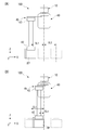
- FIG. 8 is a diagram showing the amount of lateral movement of the elevating and lowering drive unit 43 by the lateral ejection mechanism 45 during transfer.
- FIG. 8A shows an example in which the lateral projection amount is large
- FIG. 8B shows an example in which the lateral projection amount is small.
- the amount of horizontal movement of the elevating/lowering drive unit 43 by the horizontal movement mechanism 45 is determined by the position of the transfer destination S. As shown in FIG. 8A, when the transfer destination S is located directly below the main body section 40, the elevating drive section 43 does not cause the elevating drive section 43 to laterally move out of the elevating table 42, and the elevating drive section 43 moves the elevating table 42. By moving up and down, the article FP can be delivered.
- the article FP may be delivered with the lateral ejection mechanism 45 having the maximum lateral ejection amount SL1 in the ⁇ X direction.
- the article FP may be delivered with the lateral ejection mechanism 45 having the maximum lateral ejection amount SL2 in the +X direction. Note that the maximum lateral projection amounts SL1 and SL2 are set in a state where there is still room for lateral projection.
- FIG. 8A shows a case where the lifting table 42 (gripper 42a) holds the article FP (when unloading), but when the lifting table 42 does not hold the article FP (when grabbing the article).
- the adjusting unit 81 adjusts the amount of lateral movement of the elevating and lowering drive unit 43 by the lateral ejection mechanism 45 when the article FP is held (when unloading) and when the elevating table 42 does not hold the article FP (carrying load). And), and adjust with different values.
- the sideways-out mechanism 45 can perform sideways-out in the +X direction or the ⁇ X direction with an arbitrary sideways-out amount SLn.
- the sideward transfer mechanism 45 is set to the sideward transfer amount SLn in the ⁇ X direction. I do.
- the amount of flexure of the side-by-side mechanism 45 changes depending on the amount of side-by-side movement of the elevating and lowering drive unit 43 by the side-by-side mechanism 45, and the amount of deviation of the elevating table 42 in the X direction from directly above the transfer destination S also changes. Further, similarly to the above, when the article FP is held (when unloading) and when the lifting platform 42 does not hold the article FP (when grabbing a load), the amount of flexure of the side-feed mechanism 45 varies. different.
- the adjusting unit 81 adjusts the lateral ejection amount of the elevating drive unit 43 by the lateral ejection mechanism 45 based on the presence or absence of the article FP on the elevating table 42 according to the lateral ejection amount of the lateral ejection mechanism 45. Further, after being horizontally extended by the horizontal ejection mechanism 45, the descending amount of the elevating table 42 varies depending on the height of the transfer destination S. For example, when the irradiation direction of the laser light L1 is out of the reflection plate 49, and when the laser light L2 is emitted. The irradiation direction may deviate from the predetermined direction. In such a case, the adjustment unit 81 adjusts the irradiation direction of the laser light L1 and the irradiation direction of the laser light L2.
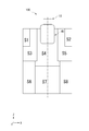
- FIG. 9 is a diagram showing an example of the transfer destination of the article FP.
- transfer destinations S for the transport vehicle 100 eight transfer destinations S1 to S8 different in the X direction and the Z direction are arranged.
- the transfer destinations S1 to S8 are shown in one diagram for convenience, but the transfer destinations S1 to S8 are arranged at different positions in the Y direction.
- eight transfer destinations S1 to S8 are shown in FIG. 9, eight or more transfer destinations, for example, transfer destinations between transfer destinations S3 and S4, transfer destinations S6 and S7, and so on.
- the transfer destination between the transfer destinations S3 and S6 may be set.
- the ⁇ X side is represented as the left side and the +X side is represented as the right side.
- the transfer destination S1 is a left transfer destination.
- the transfer destination S2 is a right transfer destination.
- the transfer destination S3 is a left high place transfer destination.
- the transfer destination S4 is a high place transfer destination.
- the transfer destination S5 is a right high place transfer destination.
- the transfer destination S6 is a left low place transfer destination.
- the transfer destination S7 is a low place transfer destination.
- the transfer destination S8 is a right low place transfer destination.
- FIG. 10 is a diagram showing an example in which transfer destinations S1 to S8 of the article FP shown in FIG. 9 are indicated by areas. As shown in FIG. 10, when the transfer destination is included in the area indicated by S1, the transfer destination is S1. Similarly, when the transfer destinations are included in the areas shown in S2 to S8, the transfer destinations are set to S2 to S8, respectively.
- the information of such transfer destinations S1 to S8 is stored in the storage unit 82 (see FIG. 1) of the control unit 80 as, for example, a data table.
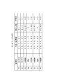
- FIG. 11 is a diagram showing an example of a data table DT1 relating to the positions of the transfer destinations S1 to S8, the lateral extension amount of the elevating drive unit 43 by the lateral ejection mechanism 45, and the descending amount of the elevating table 42 by the elevating drive unit 43. ..
- the positions (coordinate values: X1, Y1, Z1, etc.) of the eight transfer destinations S1 to S8 shown in FIG. 9 or 10 and the transfer destinations S1 to S8 are set.
- sideways out amounts SL1, SL2, SLX1, SLX2, and descending amounts H1, H2, H3 of the elevating table 42 are stored.
- the transfer destinations S1 and S2, the transfer destinations S3, S4 and S5, and the transfer destinations S6, S7 and S8 are at the same position in the traveling direction of the transport vehicle 100 (the same Y1, Y2, However, the position may be shifted in the traveling direction of the transport vehicle 100.
- SLX1 and SLX2 in the data table DT1 are values calculated by the lateral projection amount (position of the transfer destination) of the elevation drive unit 43 by the lateral projection mechanism 45.
- a predetermined calculation formula is stored in the storage unit 82, and the lateral adjustment amount SLLX1 and the like are calculated by this calculation formula.
- the sideways amount is adjusted and the direction of the sensor is adjusted (the irradiation direction of the laser beam L1 of the shake detection sensor 47, the irradiation direction of the laser beam L2 of the look-down sensor 48). ) May be required at least one of.
- the adjusting unit 81 adjusts the sideways amount, the descending amount, and the sensor orientation according to the positions of the transfer destinations S1 to S8 and the presence or absence of the article FP.
- the adjusting unit 81 adjusts the sideways amount, the descending amount, and the sensor orientation from the data table DT2 stored in the storage unit 82 according to the positions of the transfer destinations S1 to S8.
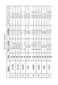
- FIG. 12 is a diagram showing an example of the data table DT2 relating to the lateral adjustment amount and the adjustment of the sensor orientation.
- the adjustment unit 81 acquires information regarding the transfer destinations S1 to S8 of the article FP from the data table DT1 of the storage unit 82, and adjusts the sideways amount required at the target transfer destination and the orientation of the sensor 44. , Or both of them are performed based on the data table DT2.
- the data table DT2 includes data relating to the descending adjustment amount for adjusting the descending amount of the elevating table 42. When the side-out mechanism 45 bends, the distance between the transfer destination S and the lift 42 also changes.
- the adjusting unit 81 adjusts the descending amounts H1, H2, and H3 of the elevating table 42 acquired from the data table DT1 based on the data table DT2, according to the laterally extending amount of the elevating and lowering driving unit 43 by the laterally ejecting mechanism 45.
- the lateral ejection adjustment with respect to the lateral ejection amount SL1 by the lateral ejection mechanism 45 is performed.
- the amount ( ⁇ X shown in FIG. 2) is SLL1
- the lowering adjustment amount with respect to the lowering amount H1 of the lifting table 42 is H1A
- the actuators 66a and 76a of the sensor 44 are off.
- the sideways adjustment amount is SLL2
- the downward adjustment amount is H1B
- the actuators 66a and 76a of the sensor 44 are provided. Is off.
- Other data transfer destinations are as shown in the data table DT2.
- the transfer destinations S4 and S7 do not cause the side-by-side mechanism 45 to horizontally extend the elevating and lowering drive unit 43, so that the side-out mechanism 45 is not bent, and the adjustment unit 81 adjusts and lowers the side-out amount.
- the quantity and sensor orientation are not adjusted.
- SLLX1, SLLX2, SLRX1 and SLRX2 in the data table DT2 are values calculated by the horizontal movement amount of the elevating drive unit 43 by the horizontal movement mechanism 45.
- a predetermined calculation formula is stored in the storage unit 82, and the lateral adjustment amount SLLX1 and the like are calculated by this calculation formula.
- turning on (1) of the actuators 66a and 76a of the sensor 44 means that the irradiation direction of the laser light L1 or the like is inclined to the +X side.
- turning on (2) means that the irradiation direction of the laser light L1 or the like is inclined to the ⁇ X side.
- the processing load on the control unit 80 can be reduced.
- the horizontal adjustment amounts SLL1, SLL2, SLR1, SLR2, SLLX1, SLLX2, SLRX1, SLRX2, and the downward adjustment amounts H1A, H1B, H1C, H1D, H2A, H2B, H2C, H2D, H3A, H3B, H3C, H3D. May be a value obtained by actually unloading or grasping the article FP from each of the transfer destinations S1 to S8, or a value obtained by simulation.
- the data table DT2 is set for each transport vehicle 100 including the machine difference of the own vehicle. In other words, even if the sideways-out mechanism 45 has the same sideward-outside amount, the deflection amount of the side-outside mechanism 45 differs depending on the rigidity of each carrier vehicle 100. Therefore, by using the data table DT2 set for each transport vehicle 100, each transport vehicle 100 can accurately unload or grasp the article FP with respect to each transfer destination S1 to S8.
- FIG. 13 is a diagram showing another example of the carrier vehicle according to the present embodiment.
- two upper and lower rails R are provided in the processing chamber PR, and the transport vehicle 100 travels on each rail R.
- the laser light L2 emitted from the look-down sensor 48 mounted on the upper transport vehicle 100 is tilted toward the ⁇ X side due to the bending of the side-out mechanism 45.
- the laser beam L2 is irradiated to the lower transport vehicle 100, and the look-down sensor 48 may erroneously detect an abnormality, and the operation of the transport vehicle 100 may be unnecessarily stopped.
- the adjusting unit 81 corrects the irradiation direction of the laser beam L2 emitted from the look-down sensor 48 to the +X side according to the amount of horizontal movement of the elevating drive unit 43 by the horizontal movement mechanism 45. To do. As a result, the laser beam L2 emitted from the look-down sensor 48 is corrected in the emission direction L2a, and is separated from the lower transport vehicle 100, so that the look-down sensor 48 can prevent erroneous detection.
- the operation of each unit of the transport vehicle 100 is performed by the control unit 80.
- the control unit 80 drives the traveling drive unit 10 to cause the transport vehicle 100 to travel along the rail R.
- the control unit 80 may cause the side-out mechanism 45 to project to the +X side or the ⁇ X side in parallel with the traveling of the transport vehicle 100, or may not project it.
- the control unit 80 when placing the article FP held by the gripper 42a on the transfer destination S (see FIG. 1), or when holding the article FP placed on the transfer destination S by the gripper 42a, The transport vehicle 100 is stopped at a predetermined position corresponding to the transfer destination S.
- the stop position of the transport vehicle 100 is, for example, a position directly above the transfer destination S or a position laterally displaced from directly above the transfer destination S.
- the control unit 80 causes the vertical drive mechanism 45 to project the lifting drive unit 43 to the side of the main body unit 40.
- the control unit 80 acquires in advance the lateral projection amount of the elevation drive unit 43 by the lateral projection mechanism 45 according to the transfer destination S (see the data table DT1 in FIG. 11).
- the adjusting unit 81 adjusts at least one of the amount of lateral movement of the elevating and lowering drive unit 43 by the lateral ejection mechanism 45 and the orientation of the sensor 44 according to the transfer destination S based on the data table DT2 of FIG. ..
- the adjustment by the adjusting unit 81 may be performed before the horizontal movement of the elevating and lowering drive unit 43 by the horizontal ejection mechanism 45 or during the horizontal ejection of the elevating and lowering drive unit 43 by the horizontal ejection mechanism 45. May be.
- the elevating table 42 is arranged immediately above the transfer destination S, the irradiation direction of the laser beam L1 emitted from the shake detection sensor 47 is prevented from deviating from the reflection plate 49, and the look The laser light L2 emitted from the down sensor 48 is appropriately emitted toward the vicinity of the transfer destination S. Further, the adjusting unit 81 adjusts the descending amount of the elevating table 42. As described above, the adjustment by the adjusting unit 81 differs depending on whether the gripper 42a is holding the article FP or not holding the article FP (see the data table DT2 in FIG. 12).
- control unit 80 lowers the lift table 42 to place the article FP held by the gripper 42a on the transfer destination S, or lowers the lift table 42 to be placed on the transfer destination S.
- the gripping item 42a is gripped by the gripper 42a.
- control unit 80 raises the elevating table 42 and then drives the sideways mechanism 45 to house the elevating table 42 (article FP) in the main body section 40.
- the control unit 80 drives the traveling drive unit 10 after the elevating table 42 is housed in the main body unit 40 to drive the transport vehicle 100 to travel along the rail R.
- the article FP is transferred to the transfer destination according to the amount of lateral movement of the elevating/lowering drive unit 43 by the laterally ejecting mechanism 45 and the descending amount of the elevating/lowering table 42 by the elevating/lowering drive unit 43.
- the article FP can be accurately delivered to the destination.
- the orientation of the sensor 44 provided in the elevating/lowering drive unit 43 according to the sideways-out amount and the descending amount of the elevating table 42 it is possible to orient the sensor 44 in a target direction. It is possible to suppress erroneous detection while ensuring proper operation of the.
- the correction mechanism described above is an example, and a correction mechanism having another configuration may be applied.
- the sensor 44 is not limited to the shake detection sensor 47 and the look-down sensor 48, and may be any sensor that emits a detection wave having directivity.
Landscapes
- Engineering & Computer Science (AREA)
- Mechanical Engineering (AREA)
- Transportation (AREA)
- Warehouses Or Storage Devices (AREA)
- Container, Conveyance, Adherence, Positioning, Of Wafer (AREA)
- Vehicle Body Suspensions (AREA)
- Control Of Position, Course, Altitude, Or Attitude Of Moving Bodies (AREA)
Abstract
Description
L1、L2・・・レーザ光
R・・・レール(軌道)
S、S1からS8・・・移載先
10・・・走行駆動部
40・・・移載装置
41・・・本体部
42・・・昇降台
42a・・・グリッパ(保持部)
43・・・昇降駆動部
43a・・・ベルト(吊持部材)
44・・・センサ
45・・・横出し機構
46・・・補正機構
47・・・揺れ検出センサ
48・・・ルックダウンセンサ
49・・・反射板
51・・・上段部
52・・・中段部
53・・・下段部
54・・・駆動装置
60・・・第1補正機構
66a、76a・・・アクチュエータ
70・・・第2補正機構
80・・・制御部
81・・・調整部
82・・・記憶部
100・・・搬送車
Claims (6)
- 軌道を走行する走行部と、
前記走行部に連結されて前記走行部の走行により移動する本体部と、
物品を保持する保持部を有しかつ前記本体部に対して昇降可能な昇降台と、
可撓性を有する吊持部材の繰り出し及び巻き取りにより前記昇降台を昇降させる昇降駆動部と、
前記昇降駆動部を片持ち支持した状態で前記本体部の側方に突出させる横出し機構と、
前記横出し機構による前記昇降駆動部の横出し量、及び前記昇降駆動部による前記昇降台の下降量に応じて、移載先に対して物品を渡す場合と物品を受け取る場合とでの前記横出し量の調整、及び前記昇降駆動部に備えるセンサの向きの調整、のうちいずれか一方又は双方を行う調整部と、を備える、搬送車。 - 前記センサは、下方の所定位置に向けて指向性を有する検出波を照射し、
前記調整部は、前記検出波の照射方向のずれを補正するように前記センサの向きを調整する、請求項1に記載の搬送車。 - 前記センサは、前記検出波の照射方向を変えるためのアクチュエータを備え、
前記調整部は、前記アクチュエータを駆動することにより前記検出波の照射方向のずれを補正する、請求項2に記載の搬送車。 - 前記本体部は、物品を受け渡しする複数の前記移載先のそれぞれについて、前記横出し機構による前記昇降駆動部の前記横出し量、及び前記移載先までの前記下降量に関するデータテーブルが記憶された記憶部を備え、
前記調整部は、前記記憶部に記憶されている前記データテーブルから物品の前記移載先に関する情報を取得して、その情報に基づいて前記横出し量の調整、及び前記昇降駆動部に備えるセンサの向きの調整、のうちいずれか一方又は双方を行う、請求項1から請求項3のいずれか一項に記載の搬送車。 - 前記調整部は、前記データテーブルが示す前記横出し量が第1の特定値である場合に、
前記データテーブルが示す前記下降量が第1の閾値未満であれば、前記横出し量の調整、及び前記昇降駆動部に備える前記センサの向きの調整の双方を行わず、
前記データテーブルが示す前記下降量が前記第1の閾値以上であれば、前記横出し量の調整、及び前記昇降駆動部に備える前記センサの向きの調整、のうちいずれか一方又は双方を行う、請求項4に記載の搬送車。 - 前記調整部は、前記データテーブルが示す前記下降量が第2の特定値である場合に、
前記データテーブルが示す前記横出し量が第2の閾値未満であれば、前記横出し量の調整、及び前記昇降駆動部に備える前記センサの向きの調整の双方を行わず、
前記データテーブルが示す前記横出し量が前記第2の閾値以上であれば、前記横出し量の調整、及び前記昇降駆動部に備える前記センサの向きの調整、のうちいずれか一方又は双方を行う、請求項4又は請求項5に記載の搬送車。
Priority Applications (6)
| Application Number | Priority Date | Filing Date | Title |
|---|---|---|---|
| JP2020559896A JP7338640B2 (ja) | 2018-12-14 | 2019-11-20 | 搬送車 |
| EP19896209.4A EP3896006A4 (en) | 2018-12-14 | 2019-11-20 | HANDLING VEHICLE |
| CN201980081416.1A CN113165807B (zh) | 2018-12-14 | 2019-11-20 | 输送车 |
| KR1020217017528A KR102502879B1 (ko) | 2018-12-14 | 2019-11-20 | 반송차 |
| US17/312,454 US12119249B2 (en) | 2018-12-14 | 2019-11-20 | Conveyance vehicle |
| SG11202106155VA SG11202106155VA (en) | 2018-12-14 | 2019-11-20 | Conveyance vehicle |
Applications Claiming Priority (2)
| Application Number | Priority Date | Filing Date | Title |
|---|---|---|---|
| JP2018234468 | 2018-12-14 | ||
| JP2018-234468 | 2018-12-14 |
Publications (1)
| Publication Number | Publication Date |
|---|---|
| WO2020121765A1 true WO2020121765A1 (ja) | 2020-06-18 |
Family
ID=71076302
Family Applications (1)
| Application Number | Title | Priority Date | Filing Date |
|---|---|---|---|
| PCT/JP2019/045448 Ceased WO2020121765A1 (ja) | 2018-12-14 | 2019-11-20 | 搬送車 |
Country Status (8)
| Country | Link |
|---|---|
| US (1) | US12119249B2 (ja) |
| EP (1) | EP3896006A4 (ja) |
| JP (1) | JP7338640B2 (ja) |
| KR (1) | KR102502879B1 (ja) |
| CN (1) | CN113165807B (ja) |
| SG (1) | SG11202106155VA (ja) |
| TW (1) | TWI816000B (ja) |
| WO (1) | WO2020121765A1 (ja) |
Cited By (5)
| Publication number | Priority date | Publication date | Assignee | Title |
|---|---|---|---|---|
| WO2022107448A1 (ja) * | 2020-11-18 | 2022-05-27 | 村田機械株式会社 | 搬送車システム |
| WO2022176288A1 (ja) * | 2021-02-17 | 2022-08-25 | 村田機械株式会社 | 天井搬送車 |
| US20230278833A1 (en) * | 2022-01-28 | 2023-09-07 | Daifuku Co., Ltd. | Article Transport Vehicle |
| WO2024154380A1 (ja) * | 2023-01-19 | 2024-07-25 | 村田機械株式会社 | 天井搬送車及びセンサの照射方向決定方法 |
| WO2024252719A1 (ja) * | 2023-06-06 | 2024-12-12 | 村田機械株式会社 | 天井搬送車 |
Families Citing this family (4)
| Publication number | Priority date | Publication date | Assignee | Title |
|---|---|---|---|---|
| US11862494B2 (en) * | 2020-07-09 | 2024-01-02 | Changxin Memory Technologies, Inc. | Crane monitoring system and method |
| KR102547923B1 (ko) * | 2021-11-01 | 2023-06-26 | 주식회사 에스에프에이 | 이송대차 및 그를 구비하는 이송대차 시스템 |
| CN116300916B (zh) * | 2023-02-24 | 2026-03-20 | 深圳市海柔创新科技有限公司 | 基于机器人学习的机器人移动路径调整方法及相关装置 |
| JP7794167B2 (ja) * | 2023-05-11 | 2026-01-06 | 株式会社ダイフク | 天井搬送車 |
Citations (7)
| Publication number | Priority date | Publication date | Assignee | Title |
|---|---|---|---|---|
| JP2009166987A (ja) * | 2008-01-18 | 2009-07-30 | Toyota Industries Corp | 自動倉庫用スタッカークレーンにおける姿勢制御装置 |
| JP2009208888A (ja) * | 2008-03-04 | 2009-09-17 | Asyst Technologies Japan Inc | 搬送車 |
| JP2011057357A (ja) * | 2009-09-09 | 2011-03-24 | Murata Machinery Ltd | 移載装置 |
| JP5636849B2 (ja) | 2010-09-30 | 2014-12-10 | 村田機械株式会社 | 移載システム |
| JP2015074547A (ja) * | 2013-10-10 | 2015-04-20 | 株式会社ダイフク | 天井搬送車 |
| WO2017199593A1 (ja) | 2016-05-20 | 2017-11-23 | 村田機械株式会社 | 搬送車及び搬送方法 |
| WO2018146926A1 (ja) * | 2017-02-07 | 2018-08-16 | 村田機械株式会社 | 搬送システム及び搬送方法 |
Family Cites Families (10)
| Publication number | Priority date | Publication date | Assignee | Title |
|---|---|---|---|---|
| JPS5514874A (en) | 1978-07-18 | 1980-02-01 | Kobe Steel Ltd | Exhausting apparatus for vacuum degassing of molten steel |
| US20050095093A1 (en) * | 2002-02-25 | 2005-05-05 | Rudolf Hansl | Storage retrieval system comprising a load receiving element |
| JP5287227B2 (ja) * | 2008-12-25 | 2013-09-11 | 村田機械株式会社 | 搬送台車 |
| JP5500371B2 (ja) | 2010-07-23 | 2014-05-21 | 株式会社ダイフク | 物品搬送設備 |
| JP5382470B2 (ja) * | 2010-11-04 | 2014-01-08 | 村田機械株式会社 | 搬送システム及び搬送方法 |
| JP6303556B2 (ja) * | 2014-02-05 | 2018-04-04 | 東京エレクトロン株式会社 | 基板搬送機構の位置検出方法、記憶媒体及び基板搬送機構の位置検出装置 |
| JP2017154840A (ja) * | 2016-02-29 | 2017-09-07 | 株式会社ダイフク | 物品搬送設備 |
| JP6597551B2 (ja) | 2016-10-21 | 2019-10-30 | 株式会社ダイフク | 物品搬送設備 |
| CN110235235B (zh) | 2017-04-06 | 2023-01-06 | 村田机械株式会社 | 桥式输送车系统以及示教单元 |
| JP2018176950A (ja) * | 2017-04-11 | 2018-11-15 | 村田機械株式会社 | 走行車システム |
-
2019
- 2019-11-20 WO PCT/JP2019/045448 patent/WO2020121765A1/ja not_active Ceased
- 2019-11-20 EP EP19896209.4A patent/EP3896006A4/en active Pending
- 2019-11-20 KR KR1020217017528A patent/KR102502879B1/ko active Active
- 2019-11-20 US US17/312,454 patent/US12119249B2/en active Active
- 2019-11-20 SG SG11202106155VA patent/SG11202106155VA/en unknown
- 2019-11-20 JP JP2020559896A patent/JP7338640B2/ja active Active
- 2019-11-20 CN CN201980081416.1A patent/CN113165807B/zh active Active
- 2019-12-06 TW TW108144748A patent/TWI816000B/zh active
Patent Citations (7)
| Publication number | Priority date | Publication date | Assignee | Title |
|---|---|---|---|---|
| JP2009166987A (ja) * | 2008-01-18 | 2009-07-30 | Toyota Industries Corp | 自動倉庫用スタッカークレーンにおける姿勢制御装置 |
| JP2009208888A (ja) * | 2008-03-04 | 2009-09-17 | Asyst Technologies Japan Inc | 搬送車 |
| JP2011057357A (ja) * | 2009-09-09 | 2011-03-24 | Murata Machinery Ltd | 移載装置 |
| JP5636849B2 (ja) | 2010-09-30 | 2014-12-10 | 村田機械株式会社 | 移載システム |
| JP2015074547A (ja) * | 2013-10-10 | 2015-04-20 | 株式会社ダイフク | 天井搬送車 |
| WO2017199593A1 (ja) | 2016-05-20 | 2017-11-23 | 村田機械株式会社 | 搬送車及び搬送方法 |
| WO2018146926A1 (ja) * | 2017-02-07 | 2018-08-16 | 村田機械株式会社 | 搬送システム及び搬送方法 |
Cited By (13)
| Publication number | Priority date | Publication date | Assignee | Title |
|---|---|---|---|---|
| US12434907B2 (en) | 2020-11-18 | 2025-10-07 | Murata Machinery, Ltd. | Transport vehicle system |
| JPWO2022107448A1 (ja) * | 2020-11-18 | 2022-05-27 | ||
| JP7347692B2 (ja) | 2020-11-18 | 2023-09-20 | 村田機械株式会社 | 搬送車システム |
| WO2022107448A1 (ja) * | 2020-11-18 | 2022-05-27 | 村田機械株式会社 | 搬送車システム |
| WO2022176288A1 (ja) * | 2021-02-17 | 2022-08-25 | 村田機械株式会社 | 天井搬送車 |
| JPWO2022176288A1 (ja) * | 2021-02-17 | 2022-08-25 | ||
| JP7306596B2 (ja) | 2021-02-17 | 2023-07-11 | 村田機械株式会社 | 天井搬送車 |
| US12588468B2 (en) | 2021-02-17 | 2026-03-24 | Murata Machinery, Ltd. | Overhead transport vehicle |
| US20230278833A1 (en) * | 2022-01-28 | 2023-09-07 | Daifuku Co., Ltd. | Article Transport Vehicle |
| US12459788B2 (en) * | 2022-01-28 | 2025-11-04 | Daifuku Co., Ltd. | Article transport vehicle |
| WO2024154380A1 (ja) * | 2023-01-19 | 2024-07-25 | 村田機械株式会社 | 天井搬送車及びセンサの照射方向決定方法 |
| WO2024252719A1 (ja) * | 2023-06-06 | 2024-12-12 | 村田機械株式会社 | 天井搬送車 |
| DE112024002022T5 (de) | 2023-06-06 | 2026-02-26 | Murata Machinery, Ltd. | Sich hängend bewegendes transportfahrzeug |
Also Published As
| Publication number | Publication date |
|---|---|
| EP3896006A1 (en) | 2021-10-20 |
| JPWO2020121765A1 (ja) | 2021-10-21 |
| CN113165807A (zh) | 2021-07-23 |
| EP3896006A4 (en) | 2022-08-10 |
| US12119249B2 (en) | 2024-10-15 |
| KR102502879B1 (ko) | 2023-02-23 |
| KR20210088667A (ko) | 2021-07-14 |
| JP7338640B2 (ja) | 2023-09-05 |
| TWI816000B (zh) | 2023-09-21 |
| US20220059380A1 (en) | 2022-02-24 |
| SG11202106155VA (en) | 2021-07-29 |
| CN113165807B (zh) | 2022-07-26 |
| TW202026215A (zh) | 2020-07-16 |
Similar Documents
| Publication | Publication Date | Title |
|---|---|---|
| JP7338640B2 (ja) | 搬送車 | |
| JP6617832B2 (ja) | 搬送車及び搬送方法 | |
| KR102230179B1 (ko) | 스태커 크레인 | |
| KR102422206B1 (ko) | 반송 장치 | |
| WO2018003287A1 (ja) | 搬送システム | |
| CN107055013A (zh) | 物品输送设备 | |
| CN111038986B (zh) | 容纳系统 | |
| JP2018034991A (ja) | 搬送装置、搬送方法、およびプログラム | |
| CN117043036B (zh) | 高架搬送车 | |
| TW202406829A (zh) | 高架搬送車 | |
| JP5151276B2 (ja) | 搬送システム | |
| JP7416280B2 (ja) | 保管棚及び天井搬送車システム | |
| CN113510689B (zh) | 工业用机器人和工业用机器人的控制方法 | |
| WO2023218818A1 (ja) | 天井搬送車 | |
| CN120457533A (zh) | 高架输送车以及传感器的照射方向决定方法 | |
| CN115924537A (zh) | 工业用机器人和工业用机器人的控制方法 | |
| CN120229555A (zh) | 用于运送物品的系统 | |
| CN120660183A (zh) | 空中搬送车 |
Legal Events
| Date | Code | Title | Description |
|---|---|---|---|
| 121 | Ep: the epo has been informed by wipo that ep was designated in this application |
Ref document number: 19896209 Country of ref document: EP Kind code of ref document: A1 |
|
| ENP | Entry into the national phase |
Ref document number: 20217017528 Country of ref document: KR Kind code of ref document: A |
|
| ENP | Entry into the national phase |
Ref document number: 2020559896 Country of ref document: JP Kind code of ref document: A |
|
| NENP | Non-entry into the national phase |
Ref country code: DE |
|
| ENP | Entry into the national phase |
Ref document number: 2019896209 Country of ref document: EP Effective date: 20210714 |