WO2020121795A1 - Roue fermée et son procédé de fabrication - Google Patents
Roue fermée et son procédé de fabrication Download PDFInfo
- Publication number
- WO2020121795A1 WO2020121795A1 PCT/JP2019/046046 JP2019046046W WO2020121795A1 WO 2020121795 A1 WO2020121795 A1 WO 2020121795A1 JP 2019046046 W JP2019046046 W JP 2019046046W WO 2020121795 A1 WO2020121795 A1 WO 2020121795A1
- Authority
- WO
- WIPO (PCT)
- Prior art keywords
- brazing
- shroud
- blade portion
- mass
- impeller
- Prior art date
- Legal status (The legal status is an assumption and is not a legal conclusion. Google has not performed a legal analysis and makes no representation as to the accuracy of the status listed.)
- Ceased
Links
Images


Classifications
-
- F—MECHANICAL ENGINEERING; LIGHTING; HEATING; WEAPONS; BLASTING
- F04—POSITIVE - DISPLACEMENT MACHINES FOR LIQUIDS; PUMPS FOR LIQUIDS OR ELASTIC FLUIDS
- F04D—NON-POSITIVE-DISPLACEMENT PUMPS
- F04D29/00—Details, component parts, or accessories
- F04D29/26—Rotors specially for elastic fluids
- F04D29/28—Rotors specially for elastic fluids for centrifugal or helico-centrifugal pumps for radial-flow or helico-centrifugal pumps
- F04D29/284—Rotors specially for elastic fluids for centrifugal or helico-centrifugal pumps for radial-flow or helico-centrifugal pumps for compressors
-
- F—MECHANICAL ENGINEERING; LIGHTING; HEATING; WEAPONS; BLASTING
- F04—POSITIVE - DISPLACEMENT MACHINES FOR LIQUIDS; PUMPS FOR LIQUIDS OR ELASTIC FLUIDS
- F04D—NON-POSITIVE-DISPLACEMENT PUMPS
- F04D29/00—Details, component parts, or accessories
- F04D29/26—Rotors specially for elastic fluids
- F04D29/28—Rotors specially for elastic fluids for centrifugal or helico-centrifugal pumps for radial-flow or helico-centrifugal pumps
-
- B—PERFORMING OPERATIONS; TRANSPORTING
- B23—MACHINE TOOLS; METAL-WORKING NOT OTHERWISE PROVIDED FOR
- B23K—SOLDERING OR UNSOLDERING; WELDING; CLADDING OR PLATING BY SOLDERING OR WELDING; CUTTING BY APPLYING HEAT LOCALLY, e.g. FLAME CUTTING; WORKING BY LASER BEAM
- B23K1/00—Soldering, e.g. brazing, or unsoldering
- B23K1/0008—Soldering, e.g. brazing, or unsoldering specially adapted for particular articles or work
-
- B—PERFORMING OPERATIONS; TRANSPORTING
- B23—MACHINE TOOLS; METAL-WORKING NOT OTHERWISE PROVIDED FOR
- B23K—SOLDERING OR UNSOLDERING; WELDING; CLADDING OR PLATING BY SOLDERING OR WELDING; CUTTING BY APPLYING HEAT LOCALLY, e.g. FLAME CUTTING; WORKING BY LASER BEAM
- B23K35/00—Rods, electrodes, materials, or media, for use in soldering, welding, or cutting
- B23K35/02—Rods, electrodes, materials, or media, for use in soldering, welding, or cutting characterised by mechanical features, e.g. shape
- B23K35/0222—Rods, electrodes, materials, or media, for use in soldering, welding, or cutting characterised by mechanical features, e.g. shape for use in soldering or brazing
- B23K35/0233—Sheets or foils
- B23K35/0238—Sheets or foils layered
-
- B—PERFORMING OPERATIONS; TRANSPORTING
- B23—MACHINE TOOLS; METAL-WORKING NOT OTHERWISE PROVIDED FOR
- B23K—SOLDERING OR UNSOLDERING; WELDING; CLADDING OR PLATING BY SOLDERING OR WELDING; CUTTING BY APPLYING HEAT LOCALLY, e.g. FLAME CUTTING; WORKING BY LASER BEAM
- B23K35/00—Rods, electrodes, materials, or media, for use in soldering, welding, or cutting
- B23K35/22—Rods, electrodes, materials, or media, for use in soldering, welding, or cutting characterised by the composition or nature of the material
- B23K35/24—Selection of soldering or welding materials proper
- B23K35/28—Selection of soldering or welding materials proper with the principal constituent melting at less than 950°C
- B23K35/286—Al as the principal constituent
-
- C—CHEMISTRY; METALLURGY
- C22—METALLURGY; FERROUS OR NON-FERROUS ALLOYS; TREATMENT OF ALLOYS OR NON-FERROUS METALS
- C22C—ALLOYS
- C22C21/00—Alloys based on aluminium
- C22C21/02—Alloys based on aluminium with silicon as the next major constituent
-
- F—MECHANICAL ENGINEERING; LIGHTING; HEATING; WEAPONS; BLASTING
- F04—POSITIVE - DISPLACEMENT MACHINES FOR LIQUIDS; PUMPS FOR LIQUIDS OR ELASTIC FLUIDS
- F04D—NON-POSITIVE-DISPLACEMENT PUMPS
- F04D29/00—Details, component parts, or accessories
- F04D29/02—Selection of particular materials
- F04D29/023—Selection of particular materials especially adapted for elastic fluid pumps
-
- F—MECHANICAL ENGINEERING; LIGHTING; HEATING; WEAPONS; BLASTING
- F05—INDEXING SCHEMES RELATING TO ENGINES OR PUMPS IN VARIOUS SUBCLASSES OF CLASSES F01-F04
- F05D—INDEXING SCHEME FOR ASPECTS RELATING TO NON-POSITIVE-DISPLACEMENT MACHINES OR ENGINES, GAS-TURBINES OR JET-PROPULSION PLANTS
- F05D2230/00—Manufacture
- F05D2230/20—Manufacture essentially without removing material
- F05D2230/23—Manufacture essentially without removing material by permanently joining parts together
- F05D2230/232—Manufacture essentially without removing material by permanently joining parts together by welding
- F05D2230/237—Brazing
-
- F—MECHANICAL ENGINEERING; LIGHTING; HEATING; WEAPONS; BLASTING
- F05—INDEXING SCHEMES RELATING TO ENGINES OR PUMPS IN VARIOUS SUBCLASSES OF CLASSES F01-F04
- F05D—INDEXING SCHEME FOR ASPECTS RELATING TO NON-POSITIVE-DISPLACEMENT MACHINES OR ENGINES, GAS-TURBINES OR JET-PROPULSION PLANTS
- F05D2300/00—Materials; Properties thereof
- F05D2300/10—Metals, alloys or intermetallic compounds
- F05D2300/12—Light metals
- F05D2300/121—Aluminium
Definitions
- the present invention relates to a closed impeller and a manufacturing method thereof.
- a casing including a suction port for sucking fluid, a discharge port for discharging the fluid, and an impeller rotatably held in the casing are provided.
- a centrifugal compressor may be used.
- the impeller of the centrifugal compressor rotates in the casing and can guide the fluid sucked from the suction port to the discharge port while compressing the fluid.
- a closed impeller including a hub held by a casing, blades protruding from the hub, and a shroud covering the blades is known. In the closed impeller, the space surrounded by the hub, the blades, and the shroud serves as a fluid passage.
- closed impellers are made by any method of cutting, precision casting or brazing.
- the hub, blades, and shroud are integrally formed by cutting the metal block.
- the range in which cutting can be performed is restricted by the structure of the processing device and the tool, and thus a closed impeller having a desired shape may not be obtained.
- Precision casting has less restrictions on the shape of the impeller than cutting, but has the problem of low dimensional accuracy. Therefore, the closed impeller obtained by precision casting may cause a reduction in the operating efficiency of the centrifugal compressor. Further, in the case of manufacturing a small impeller having a diameter of 100 mm or less, for example, the material of the mold such as gypsum tends to remain in the flow path of the molten metal after casting. Further, it is difficult to discharge the material of the mold from the impeller, and there is a problem that the manufacturing cost tends to increase.
- the impeller body in which the hub and the blade are integrally formed and the shroud are separately manufactured by machining, and then the both are joined by brazing. Therefore, the shape is less restricted than in the case where the hub, the blade, and the shroud are integrally formed by cutting. Furthermore, since the impeller body and the shroud are formed by machining, the dimensional accuracy of each component can be increased as compared with precision casting.
- Patent Document 1 in a method for manufacturing an impeller including a substantially disc-shaped disc, a cover arranged to face the disc, and a blade provided between the disc and the cover, a cover and a blade are provided. And a technique for brazing with a disc in a specific arrangement.
- an aluminum alloy which has a low specific gravity among the metals, may be used.
- a method called dip brazing is adopted.
- an impeller body having a hub and blades and a shroud that covers the blades are manufactured in advance by machining or the like.
- the shroud is attached to the impeller body with the brazing material paste containing the brazing material powder made of an Al—Si alloy and the binder interposed between the blade and the shroud to prepare an assembly.
- the impeller body and shroud are brazed by immersing this assembly in a molten flux bath.
- a brazed joint containing a brazing material is formed between the blade and the shroud after brazing.
- the closed impeller compresses fluid with high efficiency, so it rotates at high speed in the casing. Further, when the fluid is compressed in the closed impeller, the pressure in the closed impeller rises. Therefore, when manufacturing a closed impeller by brazing, it is necessary to increase the joint strength of the brazed joint.
- the present invention has been made in view of such a background, and an object of the present invention is to provide a closed impeller that can be manufactured by brazing and has a higher bonding strength between a blade and a shroud than ever before, and a method for manufacturing the same. ..
- One embodiment of the present invention is made of an aluminum alloy, and an impeller body including a hub portion and a blade portion protruding from the hub portion, A shroud covering the vane portion, Intervening between the blade portion and the shroud, and having a brazing joint for joining the blade portion and the shroud,
- the shroud is A closed impeller, which is a brazing sheet, including a core material made of an aluminum alloy and a brazing material layer disposed on the core material and located on the outermost surface facing the blade portion.
- Another aspect of the present invention is a method for producing the closed impeller of the above aspect, Prepare the impeller body, Mg: a core material made of an aluminum alloy containing 0.20% by mass or more and less than 1.80% by mass, an Al—Si alloy, having a thickness of 20 to 215 ⁇ m, and a brazing material layer arranged on the outermost surface, Prepare a brazing sheet with A molding process is applied to the brazing sheet to produce the shroud in which the brazing material layer is arranged on the surface facing the blade portion,
- a closed impeller manufacturing method comprises brazing the surface of the shroud facing the blade portion and the blade portion of the impeller body in an inert gas without using a flux.
- the shroud in the closed impeller is a brazing sheet provided with a core material made of an aluminum alloy and a brazing material existing on the outermost surface facing the blade portion, that is, the inner surface of the shroud. Then, the blade of the impeller body and the shroud are joined via a brazing joint provided with a brazing material derived from the brazing material layer of the brazing sheet. As described above, by using the shroud made of the brazing sheet, the joint strength of the brazed joint can be made higher than that of the conventional brazed joint formed by the dip brazing.
- the impeller body and the shroud made of the specific brazing sheet are separately prepared, and then brazing of both is performed without using flux.
- the brazing material layer of the brazing sheet is held on the core material. Therefore, in the above manufacturing method, it is not necessary to use a binder for holding the brazing filler metal unlike the dip brazing.
- the brazing sheet core material that constitutes the shroud contains Mg.
- Mg diffuses in the brazing material layer and moves to the surface of the shroud. Further, after brazing progresses and the brazing material layer is melted, it is eluted into the molten braze and moves to the surface of the shroud. Then, by setting the amount of Mg in the core material and the thickness of the brazing filler metal layer to the above-mentioned specific ranges, a sufficient amount of Mg is supplied to the surface of the shroud during the brazing heat and the surface of the shroud and the impeller main body is supplied by Mg. The existing oxide film can be destroyed. As a result, according to the manufacturing method, brazing can be performed without using flux.
- the manufacturing method of the above aspect can perform brazing without using the binder or flux used in the conventional dip brazing. Therefore, formation of voids in the brazed joint can be suppressed. Furthermore, the brazed joint formed after brazing is reinforced by the Mg diffused from the core. As a result, the joint strength of the brazed joint can be remarkably enhanced as compared with the brazed joint formed by the dip brazing.
- FIG. 3 is a perspective view of the closed impeller in Embodiment 1.
- FIG. 3 is an exploded perspective view of the closed impeller in Embodiment 1.
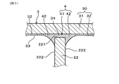
- FIG. 5 is a partial cross-sectional view of a brazed joint interposed between the shroud and the blade portion in the first embodiment.
- 5 is a partial cross-sectional view of a contact portion between a shroud and a blade portion before brazing in Embodiment 1.
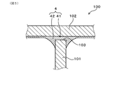
- FIG. 7 is a partial cross-sectional view showing a main part of a test piece in Example 2.
- the impeller body in the closed impeller has a hub portion and a blade portion protruding from the hub portion.
- the impeller body is held by the rotary shaft of the centrifugal compressor and rotates together with the rotary shaft in the casing of the centrifugal compressor.
- the hub portion and the blade portion may be integrally formed, for example, by cutting a block of an aluminum alloy.
- the shape of the hub portion, the shape of the blade portions, the number and arrangement of the blade portions are not particularly limited, and can be appropriately selected according to the desired compression performance and the like.
- the aluminum alloy that constitutes the impeller body an appropriate alloy can be adopted according to the desired rotation speed, compression performance, etc.
- the aluminum alloy forming the impeller body is preferably a JIS A6000 series alloy or A7000 series alloy having relatively high strength.
- the impeller body blades are covered with a shroud.
- the shroud in the closed impeller has a brazing sheet after brazing, that is, a core material made of an aluminum alloy, and a brazing material existing on the core material and facing the blade, that is, a brazing material existing on the inner surface of the shroud. doing.
- the brazing material of the shroud is formed by solidifying a part of the molten brazing material generated from the brazing sheet during the brazing heat while remaining on the surface of the core material.
- the brazing material of the shroud in the closed impeller may be formed on the surface of the core material, for example. Further, as will be described later, when the brazing sheet before brazing has an intermediate material between the core material and the brazing material, the brazing material may be formed on the surface of the intermediate material. In addition, the brazing material may be present at least at the portion of the inner surface of the shroud that is joined to the blade portion. That is, the brazing filler metal in the closed impeller may be present in a layered manner on the entire inner surface of the shroud, or may be present on a part of the inner surface.
- the aluminum alloy forming the core material an appropriate alloy can be adopted from the aluminum alloys containing Mg according to the desired rotation speed, compression performance, etc.
- the aluminum alloy constituting the core material is preferably JIS A6000 series alloy or A7000 series alloy having relatively high strength. An example of a specific composition of the core material will be described later.
- brazing joint is a concept including a brazing filler metal filled between the blade portion and the shroud core material, and a fillet extending outward from the gap between the blade portion and the shroud core material. is there.
- the brazed joint preferably has a brazing material made of an aluminum alloy containing Mg: 0.25 mass% or more.
- a brazing material made of an aluminum alloy containing Mg: 0.25 mass% or more.
- the joint strength of the brazed joint is preferably 150 MPa or more.
- the joint strength of the brazed joint is more preferably 170 MPa or more, and further preferably 200 MPa or more.
- the joint strength of the brazed joint is in accordance with JIS Z2241:2011 after cutting out a small piece from the closed impeller, including one of the brazed joints, the impeller body and the shroud joined through the brazed joint. It is a value obtained by conducting a tensile test of this small piece by the method described above.
- the closed impeller can be manufactured by the manufacturing method of the above aspect.
- the impeller body is prepared.
- the impeller body can be manufactured, for example, by machining a lump of aluminum alloy and integrally forming the hub portion and the blade portion.
- a core material made of an aluminum alloy containing Mg: 0.20 mass% or more and less than 1.80 mass% and an Al-Si alloy, having a thickness of 20 to 215 ⁇ m, and having an outermost surface And a brazing material layer disposed on the brazing material layer.
- the core material of the brazing sheet is a material that does not melt when the brazing heat is applied and forms the shape of the shroud after brazing.
- the core material is composed of an aluminum alloy containing Mg: 0.20 mass% or more and less than 1.80 mass %. More specifically, the aluminum alloy constituting the core material contains Mg: 0.20 mass% or more and less than 1.80 mass%, and the balance has a chemical component of Al (aluminum) and inevitable impurities. Good. Further, the aluminum alloy constituting the core material may contain one or more optional components in addition to Mg as an essential component. Examples of optional components in the core material include Si, Cu (copper), Mn (manganese), Zn (zinc), Ti (titanium), and the like.
- Mg in the core material diffuses from the core material when the brazing heat is applied, or elutes into the molten braze and moves to the surface of the shroud. Then, the Mg that reaches the surface of the shroud destroys the oxide film existing on the surface of the shroud and the surface of the blade portion.
- the amount of Mg in the core material can be 0.20 mass% or more, the amount of Mg reaching the surface of the shroud can be sufficiently increased, and a brazed joint can be formed between the shroud and the blade portion. Furthermore, in the brazed joint formed after brazing, the amount of Mg in the brazing material can be increased sufficiently to improve the joint strength.
- the amount of Mg in the core material is less than 0.20% by mass, the amount of Mg reaching the surface of the shroud is insufficient, so it is difficult to form a sound brazed joint between the shroud and the blade portion. There is a risk of becoming.
- the amount of Mg in the core material is 1.80 mass% or more, the melting point of the core material may be excessively lowered. Therefore, during the brazing heat, a phenomenon called erosion in which the shroud is deformed or the molten brazing penetrates into the core material is likely to occur.
- a brazing material layer made of Al-Si alloy is provided on the core material of the brazing sheet before brazing.
- the Al—Si alloy forming the brazing material layer for example, an aluminum alloy containing Si: 6% by mass or more and 13% by mass or less can be adopted. More specifically, the Al-Si alloy may contain Si: 6 mass% or less and 13 mass% or less, with the balance having a chemical composition of Al and inevitable impurities. Further, the Al-Si alloy may contain one or more optional components in addition to Si as an essential component.
- the Al—Si alloy forming the brazing material layer may contain Bi (bismuth): 0.0050 mass% or more and less than 0.060 mass% as an optional component.
- Bi in the brazing material layer can further improve the wettability of the molten brazing material and can more effectively suppress the occurrence of defective brazing.
- the amount of Bi in the brazing material layer is excessively large, the oxide film formed on the surface of the brazing material layer becomes thick in the process of manufacturing the brazing sheet, which may deteriorate the brazing property.
- the amount of Bi in the brazing material layer is more preferably 0.010 mass% or more and less than 0.060 mass %. In this case, a sound brazing joint can be more reliably formed between the blade portion and the shroud, and the joint strength can be further improved.
- Be beryllium
- Li lithium
- the like may be added as optional components in the Al-Si alloy forming the brazing material layer.
- the thickness of the brazing material layer in the brazing sheet before brazing can be appropriately set within the range of 20 to 215 ⁇ m.
- the thickness of the brazing material layer is less than 20 ⁇ m, the amount of molten brazing produced during brazing becomes insufficient, which may lead to defective brazing.
- the thickness of the brazing filler metal layer exceeds 215 ⁇ m, the distance from the core material to the surface of the brazing filler metal layer becomes excessively long, so that the amount of Mg reaching the surface of the shroud during the brazing heat may be insufficient. .. Therefore, also in this case, a brazing defect may occur.
- the brazing sheet before brazing may have a two-layer structure including a core material and a brazing material layer laminated on the core material.
- the brazing sheet has a core material made of an aluminum alloy containing Mg: 0.30 mass% or more and less than 1.80 mass% and an Al—Si alloy, and has a thickness of 20 to 215 ⁇ m.
- a brazing filler metal layer laminated on the core material wherein the brazing filler metal layer thickness X [ ⁇ m] and the Mg amount Y [mass%] in the core material are either of the following formula (1) or the following formula (2). Is preferably satisfied. Y ⁇ X/120 (where X ⁇ 36) (1) Y ⁇ 0.30 (provided that X ⁇ 36) (2)
- the brazing filler metal layer has a thickness of 36 ⁇ m or more
- the thicker the brazing filler metal layer the less the amount of Mg reaching the surface of the shroud is likely to be. Therefore, not only the amount of Mg in the core material is set within a specific range, but also the amount of Mg in the core material is increased as the thickness of the brazing material layer is increased as in the above formula (1), so that the shroud during brazing is increased. It is possible to sufficiently increase the amount of Mg that reaches the surface of and to further improve the brazing property.
- the amount of Mg in the core material may be 0.30 mass% or more as in the above formula (2).
- the brazing sheet before brazing may have a three-layer structure including a core material, an intermediate material laminated on the core material, and a brazing material layer laminated on the intermediate material.
- the configurations of the core material and the brazing material layer in the brazing sheet having the three-layer structure are the same as those of the brazing sheet having the two-layer structure.
- the amount of Mg in the core material is preferably 0.40 mass% or more and less than 1.60 mass %.
- the intermediate material is preferably composed of an aluminum alloy containing Mg: 0.80 mass% or more and less than 6.50 mass %. That is, the aluminum alloy constituting the intermediate material may contain Mg: 0.80 mass% or more and less than 6.50 mass%, and the balance having a chemical component of Al and unavoidable impurities. Further, the aluminum alloy forming the intermediate material may contain one or more optional components in addition to Mg as an essential component.
- ⁇ Mg in the intermediate material like Mg in the core material, diffuses into the brazing material layer during the brazing heat and moves toward the surface of the shroud. Then, the oxide film is destroyed by Mg reaching the surface of the shroud, and brazing can be performed.
- the amount of Mg reaching the surface of the shroud can be increased sufficiently and the brazing property can be further improved. Further, in the brazed joint formed after brazing, the amount of Mg in the brazing material can be sufficiently increased, and the joint strength can be further improved.
- the amount of Mg in the intermediate material is less than 0.80% by mass, the amount of Mg in the brazing material in the brazed joint may be insufficient, and the effect of improving the joint strength may be reduced. Further, when the amount of Mg in the intermediate material is 6.50% by mass or more, the rolling property of the intermediate material in the manufacturing process of the brazing sheet becomes low, which may make it difficult to produce the brazing sheet.
- the intermediate material may contain Si: 2.0% by mass or more and 13.0% by mass or less as an optional component.
- the melting start temperature of the intermediate material can be made lower, and diffusion of Mg from the intermediate material into the brazing material layer and elution into the molten brazing material during the brazing addition heat can be further promoted.
- the amount of Mg that reaches the surface of the shroud can be sufficiently increased, and the brazing property can be further improved.
- the content of Si in the intermediate material is less than 2.0% by mass, it may be difficult to sufficiently obtain the effect of Si.
- the content of Si in the intermediate material exceeds 13.0 mass %, the rolling property of the intermediate material in the process of manufacturing the brazing sheet becomes low, which may make it difficult to produce the brazing sheet.
- the brazing sheet After preparing the brazing sheet having the above-mentioned configuration, the brazing sheet is subjected to a molding process to produce the shroud.
- the method of molding is not particularly limited, and for example, press working can be adopted.
- the brazing sheet it is preferable to etch the surface of the brazing sheet with an acid or an alkali between the brazing sheet preparation and the brazing.
- the thick oxide film formed in the manufacturing process of the brazing sheet is weakened by etching, and the brazing property can be further improved.
- the shroud and the impeller body are brazed in an inert gas without using flux.
- Mg in the core material diffuses into the solid brazing material layer and migrates toward the surface of the shroud.
- the moving speed of Mg from the core material to the molten brazing material increases remarkably, and a large amount of Mg reaches the surface of the shroud.
- the oxide film is destroyed by the Mg that has reached the surface of the shroud, so that a brazed joint is formed between the shroud and the blade portion.
- molten brazing is formed on the entire surface of the brazing sheet.
- the molten brazing material gathers in the gap between the blade portion and the shroud due to surface tension to form a brazing joint.
- the molten brazing material remains on the surface of the core material and remains as a layered brazing material having a reduced thickness as compared with that before brazing.
- the shroud and the impeller body can be brazed to obtain a closed impeller.
- the inert gas used for brazing for example, nitrogen, argon, helium, etc. can be used.
- the pressure of the inert gas during brazing can be, for example, in the range of 1 to 110000 Pa. That is, the brazing may be performed under the atmospheric pressure or a pressure slightly higher than the atmospheric pressure, or in a vacuum of 1 Pa or more.
- the closed impeller is subjected to solution treatment, and then the closed impeller is subjected to artificial aging treatment.
- the brazing material is made into a supersaturated solid solution of Mg by heating the closed impeller to the solution treatment temperature of the brazing material and then rapidly cooling it.
- the treatment temperature in the solution treatment can be appropriately set, for example, in the range of 480 to 560°C.
- the quenching method in the solution treatment is not particularly limited, and for example, water quenching or the like can be adopted.
- the holding temperature in the artificial aging treatment can be appropriately set, for example, in the range of 160 to 220°C. Further, the holding time in the artificial aging treatment can be appropriately set within the range of 4 to 24 hours, for example.
- the closed impeller 1 is made of an aluminum alloy, and includes an impeller body 2 having a hub portion 21 and a blade portion 22 protruding from the hub portion 21, and a shroud covering the blade portion 22. 3 and 3.
- the blade portion 22 and the shroud 3 are joined by a brazed joint 4 interposed between the blade portion 22 and the shroud 3.
- the shroud 3 is a brazing sheet 30 including a core material 31 made of an aluminum alloy and a brazing material 32 arranged on the core material 31 and present on the outermost surface 33 facing the blade portion 22.
- the outermost surface 33 of the shroud 3 facing the blade portion 22 is referred to as an “inner surface 33 of the shroud 3.”
- the closed impeller 1 of the present example has a substantially truncated cone shape, and has a small diameter portion 11 having the smallest outer diameter and a large diameter portion 12 having the largest outer diameter. .. Further, the closed impeller 1 has a through hole 13 penetrating the rotation center thereof.
- the rotary shaft of the centrifugal compressor is inserted into the through hole 13 of the closed impeller 1.
- the rotating shaft of the centrifugal compressor is connected to a driving device such as a motor, and the driving force of the driving device is transmitted to the closed impeller 1 via the rotating shaft. Thereby, the closed impeller 1 can be rotated.
- the small-diameter portion 11 has a suction port 111 that opens in the axial direction of the closed impeller 1. Further, the large diameter portion 12 has a discharge port 121 that is open outward in the radial direction of the closed impeller 1.
- the suction port 111 of the closed impeller 1 is an opening surrounded by a front end portion 211 of a hub portion 21 described later, a blade portion 22, and a shroud 3.
- the outlet 121 of the closed impeller 1 is an opening surrounded by a rear end portion 213 of the hub portion 21, a blade portion 22, and the shroud 3 which will be described later.
- the flow path of the closed impeller 1 is a space surrounded by a curved surface 214 (see FIG. 2) of the hub portion 21 described later, the blade portion 22, and the shroud 3.
- the closed impeller 1 of this example can suck the fluid from the suction port 111 by rotating in the centrifugal compressor.
- the fluid sucked from the suction port 111 is guided to the discharge port 121 in the flow path while being accelerated as the closed impeller 1 rotates. Then, the fluid discharged from the discharge port 121 is compressed in the diffuser of the centrifugal compressor.
- the closed impeller 1 of this example has, as shown in FIG. 2, an impeller body 2 having a hub portion 21 and a blade portion 22, and a shroud 3 covering the impeller body 2.
- the hub portion 21 of the impeller body 2 has a substantially truncated cone shape similar to the closed impeller 1.
- the hub portion 21 has a front end portion 211 which is an end portion on the suction port 111 side, a rear end portion 213 which is an end portion on the discharge port 121 side, and a diameter expansion portion 212 which connects the front end portion 211 and the rear end portion 213.
- a through hole 13 penetrating the front end portion 211, the enlarged diameter portion 212 and the rear end portion 213.
- the through holes 13 are open at the center of the front end portion 211 and the center of the rear end portion 213, respectively.
- the enlarged diameter portion 212 gradually increases in diameter from the front end portion 211 toward the rear end portion 213. Further, the expanded diameter portion 212 has a curved surface 214 facing the shroud 3. Although not shown in the drawing, the curved surface 214 of the expanded diameter portion 212 has a curved shape such that the contour in a cross section including the rotation center of the closed impeller 1 is convex inward.
- the impeller body 2 of this example has a plurality of blade portions 22.
- the blade portion 22 is erected on the shroud 3 side from the curved surface 214 of the expanded diameter portion 212.
- the blade portion 22 has a spiral shape in a plan view viewed from the suction port 111 side, and extends over the range from the front end portion 211 to the rear end portion 213 of the hub portion 21.
- the blade portion 22 of this example has a thickness of 2 mm.
- the thickness of the blade portion 22 is not limited to the aspect of this example, and can be set as appropriate from the range of 0.2 to 5.0 mm, for example. Further, the thickness of the blade portion 22 need not be constant.
- the end surface 221 of the blade portion 22 on the shroud 3 side is joined to the shroud 3 via the brazing joint 4.
- the end surface 221 of the blade portion 22 of this example is curved along the inner surface 33 of the shroud 3 and is arranged so as to face the core material 31 of the shroud 3.
- a brazing material 34 is filled between the end surface 221 of the blade portion 22 and the core material 31.
- the brazing joint 4 can be formed with the surface bonding portion 41 in which the end surface 221 and the core material 31 are bonded to each other in a plane-to-plane relationship.
- the shroud 3 of this example has a funnel shape as shown in FIG. 2, and is arranged so as to cover the end surface 221 of the blade portion 22.
- a central opening 35 is provided at the center of the shroud 3, and as shown in FIG. 1, the front end portion 211 of the hub portion 21 is arranged in the central opening 35.
- the brazed joint 4 shown in FIG. 3 is formed over the entire length thereof.
- the shroud 3 of this example is composed of a brazing sheet 30 after brazing, as shown in FIG. That is, the shroud 3 has the core material 31 that forms the shape thereof, and the layered brazing material 32 disposed on the core material 31.
- the brazing material 32 is formed by the molten brazing material remaining on the core material 31 after the brazing heat of the brazing material 32 in the brazing sheet 30 before brazing.
- a brazed joint 4 is interposed between the shroud 3 and the blade portion 22.
- the brazed joint 4 of this example includes a surface joint portion 41 including a brazing material 34 filled in a gap between the end surface 221 of the blade portion 22 and the core material 31 of the shroud 3, and the surface joint portion 41.
- a fillet 42 made of the brazing material 34 extending outward.
- the fillet 42 is continuous with the layered brazing filler metal 32 present on the inner surface 33 of the shroud 3, and the thickness gradually increases as it approaches the blade portion 22.
- the fillet 42 has the largest thickness at the portion in contact with the side surface 222 of the blade portion 22.
- the fillet 42 in this specification refers to a portion of the brazing material 34 that is thicker than the thickness of the brazing material 32 present on the inner surface 33 of the shroud 3.
- the closed impeller 1 of this example can be manufactured, for example, by the following method. First, the impeller body 2 and the shroud 3 are separately prepared. The impeller body 2 can be obtained, for example, by machining a lump of aluminum alloy and integrally forming the hub portion 21 and the blade portion 22.
- the shroud 3 is composed of a core material 31 made of an aluminum alloy containing Mg: 0.20 mass% or more and less than 1.80 mass% and an Al—Si alloy, having a thickness of 20 to 215 ⁇ m, and arranged on the outermost surface.
- the brazing sheet 300 includes the brazing material layer 320 and the brazing material layer 320 (see FIG. 4 ).
- the shroud 3 can be manufactured by subjecting a brazing sheet including the core material 31 and the brazing material layer 320 to a molding process. When manufacturing the shroud 3 from the brazing sheet, molding processing may be performed so that the brazing material layer 320 of the brazing sheet is arranged inside the closed impeller 1, that is, on the side facing the blade portion 22.
- the shroud 3 prepared in this manner is overlapped with the blade portion 22 of the impeller body 2 to produce the assembly 10. As shown in FIG. 4, the end surface 221 of the blade portion 22 of the impeller body 2 in the assembly 10 is in contact with the brazing material layer 320 disposed on the inner surface 33 of the shroud 3.
- the assembly 10 is heated in an inert gas, and the shroud 3 and the impeller body 2 are brazed without using flux.
- the brazed joint 4 shown in FIG. 3 is formed between the shroud 3 and the blade portion 22, and the closed impeller 1 can be obtained.
- the shroud 3 in the closed impeller 1 of this example is a brazing sheet 30 after brazing including a core material 31 made of an aluminum alloy and a brazing material 32 existing on the inner surface 33 of the shroud 3.
- the blade portion 22 of the impeller body 2 and the shroud 3 are joined together via the brazing joint 4.
- brazing can be performed without using the binder or flux used in the conventional dip brazing. Therefore, formation of voids in the brazed joint 4 can be suppressed.
- the brazed joint 4 formed after brazing is reinforced by Mg diffused from the core material 31. As a result, the joint strength of the brazed joint 4 can be remarkably increased as compared with the brazed joint 4 formed by the dip brazing.
- the brazed joint 4 of this example has a surface joint portion 41 in which the blade portion 22 and the core material 31 are joined to each other in a plane.
- the brazed joint 4 of the present example has a fillet 42 formed of the brazing material 34 extending outside the surface joint 41.
- the joint area between the brazing material 34 and the blade portion 22 and the joint area between the brazing material 34 and the core material 31 in the brazed joint 4 are made wider, and the joint strength of the brazed joint 4 is further improved.
- Example 2 This example is an example in which the joint strength of the brazed joint 4 formed between the shroud 3 and the blade portion 22 is evaluated by a test piece 100 simulating the shapes of the shroud 3 and the blade portion 22.
- the same reference numerals as those used in the already-explained examples represent the same components and the like as the already-explained examples unless otherwise specified.
- the test piece 100 used in this example has a first part 101 simulating the blade portion 22 and a second part 102 simulating the shroud 3.
- the first part 101 is a flat plate made of JIS A6061 alloy and having a thickness of 3 mm.
- the second component 102 is a brazing sheet 300 (test materials 1 to 21) having a laminated structure shown in Table 1 and having a thickness of 2 mm.
- the symbol "Bal.” in Table 1 is a symbol indicating that the balance is present, and the symbol “-" is a symbol indicating that the element is not positively added.
- the content of the element indicated by the symbol “-” is specifically 0.05% by mass or less (including 0% by mass).
- the clad ratio of the brazing material layer and the intermediate material that is, the ratio (%) of the thickness of the brazing material layer or the intermediate material to the thickness of the brazing sheet 300 before brazing, is described.
- the thickness ( ⁇ m) of the brazing material layer and the intermediate material is described.
- test materials 17 and 19 were not evaluated in the subsequent steps because problems such as cracks and defective clad bonding occurred during rolling in the process of manufacturing the brazing sheet 300.
- the end face 103 of the first part 101 is abutted against the brazing material layer of the second part 102 to obtain a T-shaped assembly.
- This assembly is brazed by heating in an inert gas at atmospheric pressure or in a vacuum, so that a brazing including a surface joint 41 and a fillet 42 between the first part 101 and the second part 102.
- the joint 4 can be formed to obtain the test piece 100.
- Brazing in an inert gas at atmospheric pressure can be performed using an inert gas atmosphere furnace. Specifically, after disposing the assembly in the furnace, the inside of the furnace is purged with nitrogen gas to reduce the oxygen concentration in the furnace to 15 ppm by volume. Then, the assembly is heated until the temperature in the furnace reaches 600° C., so that the first part 101 and the second part 102 are brazed to obtain the test piece 100. After the temperature in the furnace reaches 600° C., the heating is stopped and the test piece 100 is cooled in the furnace until the molten brazing solidifies. Then, the test piece 100 is taken out of the furnace and cooled to room temperature.
- Brazing in vacuum can be performed using a vacuum furnace. Specifically, after the assembly is placed in a vacuum furnace, the assembly is heated to 550° C. while exhausting the atmosphere from the furnace. The pressure in the furnace when the temperature of the assembly reaches 550° C. is, for example, 5 ⁇ 10 ⁇ 3 to 7 ⁇ 10 ⁇ 3 Pa. After the temperature of the assembly reaches 550° C., argon gas is introduced into the furnace while continuing evacuation. Then, the assembly is heated at 600° C. while adjusting the supply amount of the argon gas so that the pressure in the furnace becomes 1 Pa or more. As a result, the first component 101 and the second component 102 are brazed to obtain the test piece 100. After the temperature in the furnace reaches 600° C., the heating is stopped and the test piece 100 is cooled in the furnace until the molten brazing solidifies. Then, the test piece 100 is taken out of the furnace and cooled to room temperature.
- the test piece 100 brazed by any of the above methods is further subjected to solution treatment and artificial aging treatment.
- the solution treatment specifically, the test piece 100 is immersed in a salt bath furnace at 550° C. for 3 minutes to be heated, and then water quenching is performed.
- the solution-treated test piece 100 is held at a temperature of 175° C. for 8 hours using an air furnace.
- the joint strength of the brazed joint 4 in the test piece 100 subjected to the above treatment can be measured as follows. First, the second component 102 is attached to the fixed chuck of the tensile tester via a jig. At this time, by restraining the second component 102 from both sides in the thickness direction with a jig, the deformation of the second component 102 during the tensile test is suppressed. Next, the first part 101 is attached to the crosshead of the tensile tester. Then, a tensile test is performed at a moving speed of the crosshead of 10 mm/min to obtain a load-displacement curve.
- the maximum load in the obtained load-displacement curve is divided by the maximum cross-sectional area of the brazed joint 4, that is, the total of the area of the fillet 42 and the area of the end face 103 of the first part 101 to obtain the brazed joint 4.
- the tensile strength of is calculated. In this example, the value of this tensile strength is the joint strength of the brazed joint 4.
- the joint strength of the brazed joint 4 in the test piece 100 brazed in an inert gas at atmospheric pressure is described.
- in vacuum in Table 2, the joint strength of the brazed joint 4 in the test piece 100 brazed in vacuum is described.
- the test materials 1 to 16, 18, and 20 to 21 have core materials containing Mg in the specific range. Therefore, according to these test materials, it is possible to form the brazed joint 4 having a joining strength of 110 MPa or more in both brazing under atmospheric pressure and brazing in vacuum. Since the joining strength of the conventional brazing joining by the dip brazing is usually about 100 MPa, these joining materials can make the joining strength of the brazing joint 4 higher than that of the dip brazing.
- test materials 1 to 13, 18, and 20 in which the amount of Mg in the core material and the amount of Mg in the intermediate material are within the above-described preferable content ranges have a bonding strength of 150 MPa or more.
- the brazed joint 4 can be formed, and the joint strength of the brazed joint 4 can be significantly improved as compared with dip brazing.
- the bonding strength of the brazed joint 4 tends to be lower than that of the test materials 1 to 13, 18, and 20. Since the amount of Mg in the core material of the test material 15 is larger than the range of the preferable content described above, erosion is likely to occur.
- the amount of Mg in the intermediate material of the test material 16 is less than the preferable range of the content described above, the effect of improving strength by Mg in the intermediate material tends to be insufficient. Since the amount of Mg or the amount of Si in the intermediate materials of the test materials 17 and 19 is larger than the specific range, it is difficult to bond the core material and the brazing material layer in the manufacturing process of the brazing sheet 300.
- the amount of Bi in the brazing material is larger than the range of the preferable content described above, so that the bonding strength of the brazed joint 4 tends to be lower than in the test materials 1 to 13 and 18.
- Example 3 This example is an example of evaluating the brazability when the impeller body 2 made of JIS A6061 alloy and the shroud 3 made of the test material shown in Table 1 were brazed.
- a block of JIS A6061 alloy is subjected to a cutting process to manufacture an impeller body 2 having an outer diameter of 40 mm.
- the shroud 3 corresponding to the impeller body 2 is manufactured.
- the impeller body 2 and the shroud 3 are brazed by the method described in Example 2 to obtain the closed impeller 1.
- the brazability can be evaluated based on the shape of the fillet 42 formed on the brazed joint 4 and the state of occurrence of a joint defect in the brazed joint 4.
- shape of the fillet 42 first, the closed impeller 1 after brazing is cut. Then, the shape of the fillet 42 in the brazed joint 4 which is visible from the cut portion is observed.
- the meanings of the symbols described in the “shape of fillet” column in Table 3 are as follows.
- A+ It has a uniform shape, the surface is smooth, and a fillet with a leg length of 0.5 mm or more is formed.
- D A state where fillets are formed intermittently or no fillets are formed
- the closed impeller 1 after brazing is cut in the same way as the shape of the fillet 42. Then, the cross section of the brazed joint 4 is observed with a microscope.
- the meanings of the symbols described in the "joint defect" column of Table 3 are as follows.
- A+ No bonding defects such as voids are present in the brazed joint 4 A: Voids having a diameter of 0.1 mm or less are present in the brazed joint 4 B: More than 0.1 mm in diameter in the brazed joint 4 Voids of 0.2 mm or less are present C: Voids having a diameter of more than 0.2 mm are present in the brazed joint 4.
- the case of the symbols A+ to B in which the size of the voids present in the brazed joint 4 is 0.2 mm or less is judged to be acceptable because the brazing property is acceptable.
- the brazing property is low, and thus it is determined as a failure.
- a brazing sheet (test materials 1 to 16, 18, 20 to 21) having a core material containing Mg in the specific range is used for brazing, so that the shroud 3 and the blade portion 22 are It can be seen that a brazed joint 4 can be formed between and.
- a layered brazing material 32 is formed on the entire inner surface of the shroud 3 after brazing, as shown in FIG.
- test materials 1 to 13, 18, and 20 in which the Mg content in the core material and the Mg content in the intermediate material are within the above-described preferable content ranges the Mg content in the core material is as described above. It is possible to improve the shape of the fillet 42 as compared with the test material 14 having a content less than the preferable range and further reduce the bonding defects.
- test materials 6 to 11, 18, and 20 in which the specific intermediate material is provided between the core material and the brazing material layer can further improve the shape of the fillet 42 as compared with the test materials other than these.
- the amount of Mg in the core material of the test material 15 is larger than the specific range, erosion is likely to occur. Therefore, in the test material 15, the shape of the fillet 42 is worse than in the test materials 1 to 13, 18, and 20, and the bonding defects are more likely to occur.
- the amount of Mg in the intermediate material of the test material 16 is less than the specific range, the effect of improving the brazing property by Mg tends to be insufficient. Since the amount of Mg or the amount of Si in the intermediate materials of the test materials 17 and 19 is larger than the specific range, it is difficult to manufacture the brazing sheet 300 as described above.
- the brazing property in the brazing material of the test material 21 is larger than the specific range, the brazing property is more likely to deteriorate than the test materials 1 to 13, 18, and 20.
- This example is an example of brazing the shroud 3 and the impeller body 2 using flux.
- the same method as brazing at atmospheric pressure in Example 3 except that a flux paste containing a flux containing Cs and a binder was applied between the impeller body 2 and the shroud 3.
- the impeller body 2 and the shroud 3 were brazed.
- Table 4 shows the shape of the fillet 42 and the evaluation result of the bonding defect in the closed impeller 1 of this example.
- the aspects of the closed impeller and the method for producing the same according to the present invention are not limited to the aspects of each of the above-described embodiments, and can be appropriately modified within a range that does not impair the gist of the present invention.
- the brazing joint 30 is provided with the brazing material 34 containing Mg: 0.25 mass% or more between the blade portion 22 and the shroud 3 by brazing using the brazing sheet 30.
- the invention related to the closed impeller formed by forming
- the present invention can be understood as an invention relating to a closed impeller having a brazed joint provided with a brazing material reinforced by Mg. That is, the above-mentioned embodiment is made of an aluminum material, and an impeller body including a hub portion and a blade portion protruding from the hub portion, A shroud made of aluminum material and covering the vane portion, Intervening between the blade portion and the shroud, and having a brazing joint for joining the blade portion and the shroud,
- the brazed joint has a brazing material made of an aluminum alloy containing Mg: 0.25 mass% or more, and can be regarded as one aspect of the invention related to the closed impeller.
- aluminum material is a concept that includes aluminum and aluminum alloys.
- Mg in the brazing material 34 in the brazing joint 4 has an action of strengthening the brazing material 34. Therefore, if it is possible to form the brazed joint 4 including the brazing material 34 containing the specific amount of Mg between the blade portion 22 and the shroud 3, it is possible to improve the joint strength of the brazed joint. be able to.
- the impeller body 2 is prepared, the brazing sheet 300 including the core material 31 and the brazing material layer 32 is prepared, and the brazing sheet 300 is subjected to a forming process to form the brazing material layer 32.
- the closed impeller 1 for brazing the inner surface 33 of the shroud 3 and the blade portion 22 of the impeller body 2 in an inert gas without using flux is included.
- the present invention can be understood as an invention in which the impeller body and the shroud are joined by a flux-free brazing method. That is, the embodiment is made of an aluminum material, an impeller body including a hub portion and a blade portion protruding from the hub portion, a shroud made of an aluminum material, and covering the blade portion, and the blade portion.
- a method for manufacturing a closed impeller which is interposed between the shroud and has a brazing joint that joins the blade portion and the shroud, Producing an assembly including the impeller body, the shroud covering the vane portion, and a brazing material disposed between the vane portion and the impeller body, It can also be regarded as an aspect of the invention relating to a method for manufacturing a closed impeller, in which the assembly is brazed in an inert gas without using a flux.
Landscapes
- Engineering & Computer Science (AREA)
- Mechanical Engineering (AREA)
- General Engineering & Computer Science (AREA)
- Chemical & Material Sciences (AREA)
- Materials Engineering (AREA)
- Metallurgy (AREA)
- Organic Chemistry (AREA)
- Structures Of Non-Positive Displacement Pumps (AREA)
Abstract
L'invention concerne une roue fermée (1) est constituée d'un alliage d'aluminium et comprend : un corps de roue (2) pourvu d'une partie de moyeu (21) et de parties d'aube (22) qui font saillie à partir de la partie de moyeu (21) ; et un flasque (3) qui recouvre les parties d'aube (22). Les parties d'aube (22) et le flasque (3) sont liés ensemble par des joints de brasage (4) interposés entre les parties d'aube (22) et le flasque (3). Le flasque (3) est une feuille de brasage (30) pourvue d'un élément de noyau (31) constitué d'un alliage d'aluminium et d'une couche de matériau de brasage (32) placée au-dessus de l'élément de noyau (31) et présente sur une surface la plus à l'extérieur (33) faisant face aux parties d'aube (22).
Priority Applications (3)
| Application Number | Priority Date | Filing Date | Title |
|---|---|---|---|
| US17/311,737 US11828293B2 (en) | 2018-12-10 | 2019-11-26 | Closed impeller and method of manufacturing the same |
| EP19895620.3A EP3879122B1 (fr) | 2018-12-10 | 2019-11-26 | Roue fermée et son procédé de fabrication |
| CN201980079735.9A CN113167288A (zh) | 2018-12-10 | 2019-11-26 | 封闭式叶轮及其制造方法 |
Applications Claiming Priority (2)
| Application Number | Priority Date | Filing Date | Title |
|---|---|---|---|
| JP2018-231031 | 2018-12-10 | ||
| JP2018231031A JP7149174B2 (ja) | 2018-12-10 | 2018-12-10 | クローズドインペラ及びその製造方法 |
Publications (1)
| Publication Number | Publication Date |
|---|---|
| WO2020121795A1 true WO2020121795A1 (fr) | 2020-06-18 |
Family
ID=71075958
Family Applications (1)
| Application Number | Title | Priority Date | Filing Date |
|---|---|---|---|
| PCT/JP2019/046046 Ceased WO2020121795A1 (fr) | 2018-12-10 | 2019-11-26 | Roue fermée et son procédé de fabrication |
Country Status (5)
| Country | Link |
|---|---|
| US (1) | US11828293B2 (fr) |
| EP (1) | EP3879122B1 (fr) |
| JP (1) | JP7149174B2 (fr) |
| CN (1) | CN113167288A (fr) |
| WO (1) | WO2020121795A1 (fr) |
Families Citing this family (5)
| Publication number | Priority date | Publication date | Assignee | Title |
|---|---|---|---|---|
| US11473592B2 (en) * | 2019-08-13 | 2022-10-18 | Emerson Climate Technologies, Inc. | Systems and methods for manufacturing a shrouded impeller |
| US12370615B2 (en) * | 2021-03-05 | 2025-07-29 | Danfoss A/S | Techniques for applying brazing material to form a shrouded impeller |
| TR2021021557A2 (tr) * | 2021-12-29 | 2023-07-21 | Kirpart Otomotiv Parcalari Sanayi Ve Ticaret Anonim Sirketi | Karişik akişli bi̇r fan tasarimi ve üreti̇m yöntemi̇ |
| CN114412829A (zh) * | 2022-01-22 | 2022-04-29 | 哈尔滨瀚成科技有限公司 | 一种叶轮和叶轮组 |
| CN119572533A (zh) * | 2024-12-02 | 2025-03-07 | 珠海格力电器股份有限公司 | 一种贯流风叶及具有该贯流风叶的贯流风机 |
Citations (7)
| Publication number | Priority date | Publication date | Assignee | Title |
|---|---|---|---|---|
| JP2005138122A (ja) * | 2003-11-04 | 2005-06-02 | Ngk Insulators Ltd | ベリリウムアルミニウム合金の接合体およびその製造方法 |
| JP2010174652A (ja) | 2009-01-27 | 2010-08-12 | Mitsubishi Heavy Ind Ltd | インペラの製造方法およびインペラ |
| JP2014077179A (ja) * | 2012-10-12 | 2014-05-01 | Uacj Corp | 高強度アルミニウム合金ブレージングシート及びその製造方法 |
| JP2016150355A (ja) * | 2015-02-17 | 2016-08-22 | 株式会社Uacj | フィレット形成用ろう材シート |
| JP2017029989A (ja) * | 2015-07-29 | 2017-02-09 | 株式会社Uacj | アルミニウム構造体の製造方法 |
| JP2017214610A (ja) * | 2016-05-30 | 2017-12-07 | 株式会社Uacj | ブレージングシート及びその製造方法並びにアルミニウム構造体のろう付方法 |
| JP2018035386A (ja) * | 2016-08-30 | 2018-03-08 | 株式会社Uacj | アルミニウム合金ブレージングシート |
Family Cites Families (22)
| Publication number | Priority date | Publication date | Assignee | Title |
|---|---|---|---|---|
| JP2676896B2 (ja) * | 1989-03-25 | 1997-11-17 | アイシン精機株式会社 | ロータの製造方法 |
| JPH04353294A (ja) * | 1991-05-30 | 1992-12-08 | Toto Ltd | 多層円板ファン |
| WO1996022854A1 (fr) * | 1995-01-23 | 1996-08-01 | Dresser-Rand Company | Procede de fixation par faisceau a haute energie produisant un double joint soude/brase |
| JP3675115B2 (ja) * | 1997-07-11 | 2005-07-27 | 株式会社日立製作所 | 電動送風機及びこの電動送風機に用いる羽根車の製造方法 |
| JPH1182379A (ja) | 1997-09-11 | 1999-03-26 | Hitachi Ltd | 電気掃除機用羽根車の製造方法 |
| JPH11324983A (ja) * | 1998-05-20 | 1999-11-26 | Hitachi Ltd | 電動送風機及びこの電動送風機に用いる羽根車 |
| US7628586B2 (en) * | 2005-12-28 | 2009-12-08 | Elliott Company | Impeller |
| CN100427261C (zh) * | 2006-12-30 | 2008-10-22 | 中国航空工业第一集团公司北京航空材料研究院 | 一种铝合金中温钎焊钎料 |
| IT1394295B1 (it) * | 2009-05-08 | 2012-06-06 | Nuovo Pignone Spa | Girante centrifuga del tipo chiuso per turbomacchine, componente per tale girante, turbomacchina provvista di tale girante e metodo di realizzazione di tale girante |
| CN101934405A (zh) | 2009-06-30 | 2011-01-05 | 上海沪工电焊机制造有限公司 | 一种钎焊方法 |
| US20110142653A1 (en) * | 2009-12-11 | 2011-06-16 | Hamilton Sundstrand Corporation | Two piece impeller |
| US8727729B2 (en) * | 2010-06-29 | 2014-05-20 | Turbocam, Inc. | Method for producing a shrouded impeller from two or more components |
| JP5535878B2 (ja) | 2010-11-11 | 2014-07-02 | 三菱重工業株式会社 | インペラの製造方法 |
| JP2013047479A (ja) * | 2011-08-29 | 2013-03-07 | Mitsubishi Heavy Ind Ltd | インペラ及びこれを備えた回転機械並びにインペラの製造方法 |
| KR20130033718A (ko) | 2011-09-27 | 2013-04-04 | 삼성테크윈 주식회사 | 회전 기계의 회전부 접합 구조 및 회전 기계의 회전부 접합 방법 |
| KR102126867B1 (ko) | 2013-09-24 | 2020-06-25 | 한화파워시스템 주식회사 | 임펠러 어셈블리 및 임펠러 어셈블리 제작방법 |
| US10697465B2 (en) * | 2014-07-04 | 2020-06-30 | Nuovo Pignone Srl | Manufacturing of a turbomachine impeller by assembling a plurality of tubular components |
| WO2016017716A1 (fr) | 2014-07-30 | 2016-02-04 | 株式会社Uacj | Feuille de brasage en alliage d'aluminium |
| EP3231545B1 (fr) | 2014-12-11 | 2019-09-18 | UACJ Corporation | Procédé de brasage |
| JP6803144B2 (ja) * | 2016-03-04 | 2020-12-23 | 株式会社エクセディ | 流体式回転羽根車 |
| JP6312968B1 (ja) | 2016-11-29 | 2018-04-18 | 株式会社Uacj | ブレージングシート及びその製造方法 |
| US11473592B2 (en) * | 2019-08-13 | 2022-10-18 | Emerson Climate Technologies, Inc. | Systems and methods for manufacturing a shrouded impeller |
-
2018
- 2018-12-10 JP JP2018231031A patent/JP7149174B2/ja active Active
-
2019
- 2019-11-26 CN CN201980079735.9A patent/CN113167288A/zh active Pending
- 2019-11-26 EP EP19895620.3A patent/EP3879122B1/fr active Active
- 2019-11-26 WO PCT/JP2019/046046 patent/WO2020121795A1/fr not_active Ceased
- 2019-11-26 US US17/311,737 patent/US11828293B2/en active Active
Patent Citations (7)
| Publication number | Priority date | Publication date | Assignee | Title |
|---|---|---|---|---|
| JP2005138122A (ja) * | 2003-11-04 | 2005-06-02 | Ngk Insulators Ltd | ベリリウムアルミニウム合金の接合体およびその製造方法 |
| JP2010174652A (ja) | 2009-01-27 | 2010-08-12 | Mitsubishi Heavy Ind Ltd | インペラの製造方法およびインペラ |
| JP2014077179A (ja) * | 2012-10-12 | 2014-05-01 | Uacj Corp | 高強度アルミニウム合金ブレージングシート及びその製造方法 |
| JP2016150355A (ja) * | 2015-02-17 | 2016-08-22 | 株式会社Uacj | フィレット形成用ろう材シート |
| JP2017029989A (ja) * | 2015-07-29 | 2017-02-09 | 株式会社Uacj | アルミニウム構造体の製造方法 |
| JP2017214610A (ja) * | 2016-05-30 | 2017-12-07 | 株式会社Uacj | ブレージングシート及びその製造方法並びにアルミニウム構造体のろう付方法 |
| JP2018035386A (ja) * | 2016-08-30 | 2018-03-08 | 株式会社Uacj | アルミニウム合金ブレージングシート |
Non-Patent Citations (1)
| Title |
|---|
| See also references of EP3879122A4 |
Also Published As
| Publication number | Publication date |
|---|---|
| US20220025898A1 (en) | 2022-01-27 |
| JP7149174B2 (ja) | 2022-10-06 |
| EP3879122A4 (fr) | 2022-01-26 |
| EP3879122A1 (fr) | 2021-09-15 |
| US11828293B2 (en) | 2023-11-28 |
| JP2020094503A (ja) | 2020-06-18 |
| EP3879122B1 (fr) | 2024-04-17 |
| CN113167288A (zh) | 2021-07-23 |
Similar Documents
| Publication | Publication Date | Title |
|---|---|---|
| WO2020121795A1 (fr) | Roue fermée et son procédé de fabrication | |
| JP4547032B1 (ja) | アルミニウム材のフラックスレスろう付け方法およびフラックスレスろう付け用アルミニウムクラッド材 | |
| JP4477668B2 (ja) | アルミニウム合金製ブレージングシート | |
| CN101443188B (zh) | 多层可钎焊薄板 | |
| JP6468983B2 (ja) | アルミニウム合金ブレージングシート、その製造方法、アルミニウム合金シート及び熱交換器 | |
| JP5054404B2 (ja) | 熱交換器用アルミニウム合金クラッド材およびブレージングシート | |
| JP6263574B2 (ja) | ブレージングシート及びその製造方法並びにアルミニウム構造体のろう付方法 | |
| JP6909744B2 (ja) | フラックスフリーろう付用アルミニウム合金ブレージングシート | |
| JP4107931B2 (ja) | アルミニウム又はアルミニウム合金材のろう付け方法およびアルミニウム合金製ブレージングシート | |
| WO2017065191A1 (fr) | Tôle à brasage en alliage d'aluminium, et procédé de brasage | |
| JP5614883B2 (ja) | アルミニウム材のフラックスレスろう付方法、フラックスレスろう付用アルミニウム合金ブレージングシートおよびフラックスレスろう付用アルミニウム合金ろう材 | |
| JP2012050995A (ja) | フラックスレスろう付用アルミニウム合金ろう材シートおよびアルミニウム材のフラックスレスろう付け方法 | |
| JP2012024827A (ja) | アルミニウム材のフラックスレスろう付方法およびフラックスレスろう付用アルミニウム合金ブレージングシート | |
| JP7210259B2 (ja) | アルミニウム接合体、その製造方法及びアルミニウム接合体に用いられるブレージングシート | |
| JP5190079B2 (ja) | アルミニウム合金製ブレージングシートの製造方法、アルミニウム合金製ブレージングシートのろう付け方法、熱交換器の製造方法、熱交換器 | |
| JP5190078B2 (ja) | アルミニウム合金製ブレージングシートのろう材およびその設計方法 | |
| WO2005031019A1 (fr) | Feuille de brasage d'aluminium | |
| JP4916646B2 (ja) | 固体高分子型燃料電池セパレータ用クラッド板およびその製造方法 | |
| JP6110173B2 (ja) | アルミニウム材のろう付方法およびろう付構造体 | |
| CN118268761A (zh) | 一种TiAl、Ti2AlNb合金用钎焊焊料、制作及钎焊方法 | |
| JP2019069474A (ja) | アルミニウム合金ブレージングシート、その製造方法、アルミニウム合金シート及び熱交換器 | |
| JP2013049085A (ja) | アルミニウム材のフラックスレスろう付方法 | |
| JP2011036914A (ja) | アルミニウム合金製ブレージングシート | |
| JP2011238720A (ja) | Bi系はんだ接合用の電子部品と基板及び電子部品実装基板 | |
| KR20210039329A (ko) | 원통형 스퍼터링 타깃, In 계 솔더재, 및, 원통형 스퍼터링 타깃의 제조 방법 |
Legal Events
| Date | Code | Title | Description |
|---|---|---|---|
| 121 | Ep: the epo has been informed by wipo that ep was designated in this application |
Ref document number: 19895620 Country of ref document: EP Kind code of ref document: A1 |
|
| NENP | Non-entry into the national phase |
Ref country code: DE |
|
| ENP | Entry into the national phase |
Ref document number: 2019895620 Country of ref document: EP Effective date: 20210610 |