WO2020121802A1 - Module de batterie de stockage - Google Patents
Module de batterie de stockage Download PDFInfo
- Publication number
- WO2020121802A1 WO2020121802A1 PCT/JP2019/046101 JP2019046101W WO2020121802A1 WO 2020121802 A1 WO2020121802 A1 WO 2020121802A1 JP 2019046101 W JP2019046101 W JP 2019046101W WO 2020121802 A1 WO2020121802 A1 WO 2020121802A1
- Authority
- WO
- WIPO (PCT)
- Prior art keywords
- storage battery
- space
- electrode
- assembly
- exhaust port
- Prior art date
- Legal status (The legal status is an assumption and is not a legal conclusion. Google has not performed a legal analysis and makes no representation as to the accuracy of the status listed.)
- Ceased
Links
Images


Classifications
-
- H—ELECTRICITY
- H01—ELECTRIC ELEMENTS
- H01M—PROCESSES OR MEANS, e.g. BATTERIES, FOR THE DIRECT CONVERSION OF CHEMICAL ENERGY INTO ELECTRICAL ENERGY
- H01M50/00—Constructional details or processes of manufacture of the non-active parts of electrochemical cells other than fuel cells, e.g. hybrid cells
- H01M50/20—Mountings; Secondary casings or frames; Racks, modules or packs; Suspension devices; Shock absorbers; Transport or carrying devices; Holders
- H01M50/204—Racks, modules or packs for multiple batteries or multiple cells
- H01M50/207—Racks, modules or packs for multiple batteries or multiple cells characterised by their shape
- H01M50/213—Racks, modules or packs for multiple batteries or multiple cells characterised by their shape adapted for cells having curved cross-section, e.g. round or elliptic
-
- H—ELECTRICITY
- H01—ELECTRIC ELEMENTS
- H01M—PROCESSES OR MEANS, e.g. BATTERIES, FOR THE DIRECT CONVERSION OF CHEMICAL ENERGY INTO ELECTRICAL ENERGY
- H01M50/00—Constructional details or processes of manufacture of the non-active parts of electrochemical cells other than fuel cells, e.g. hybrid cells
- H01M50/20—Mountings; Secondary casings or frames; Racks, modules or packs; Suspension devices; Shock absorbers; Transport or carrying devices; Holders
- H01M50/218—Mountings; Secondary casings or frames; Racks, modules or packs; Suspension devices; Shock absorbers; Transport or carrying devices; Holders characterised by the material
- H01M50/22—Mountings; Secondary casings or frames; Racks, modules or packs; Suspension devices; Shock absorbers; Transport or carrying devices; Holders characterised by the material of the casings or racks
- H01M50/222—Inorganic material
- H01M50/224—Metals
-
- H—ELECTRICITY
- H01—ELECTRIC ELEMENTS
- H01M—PROCESSES OR MEANS, e.g. BATTERIES, FOR THE DIRECT CONVERSION OF CHEMICAL ENERGY INTO ELECTRICAL ENERGY
- H01M50/00—Constructional details or processes of manufacture of the non-active parts of electrochemical cells other than fuel cells, e.g. hybrid cells
- H01M50/30—Arrangements for facilitating escape of gases
-
- Y—GENERAL TAGGING OF NEW TECHNOLOGICAL DEVELOPMENTS; GENERAL TAGGING OF CROSS-SECTIONAL TECHNOLOGIES SPANNING OVER SEVERAL SECTIONS OF THE IPC; TECHNICAL SUBJECTS COVERED BY FORMER USPC CROSS-REFERENCE ART COLLECTIONS [XRACs] AND DIGESTS
- Y02—TECHNOLOGIES OR APPLICATIONS FOR MITIGATION OR ADAPTATION AGAINST CLIMATE CHANGE
- Y02E—REDUCTION OF GREENHOUSE GAS [GHG] EMISSIONS, RELATED TO ENERGY GENERATION, TRANSMISSION OR DISTRIBUTION
- Y02E60/00—Enabling technologies; Technologies with a potential or indirect contribution to GHG emissions mitigation
- Y02E60/10—Energy storage using batteries
Definitions
- the present disclosure relates to a storage battery module, and particularly to a storage battery module that houses a plurality of storage battery cells.
- the storage battery module contains a plurality of storage battery cells. When a short circuit occurs in a storage battery cell, high temperature and high pressure gas is generated from the storage battery cell. In order to discharge this gas to the outside of the storage battery module, the storage battery module is provided with an exhaust path portion that is partitioned from a plurality of storage battery cells, and the exhaust path is connected to an exhaust port (see, for example, Patent Document 1). ).
- the inflow amount of air (oxygen) is large, the combustion temperature inside the battery module becomes high, and not only the battery that has runaway due to heat but also its adjacent battery may run out of heat (burn out).
- the present disclosure has been made in view of such circumstances, and an object thereof is to provide a technique for suppressing thermal runaway (kindling) of an adjacent battery due to high temperature combustion of the thermal runaway battery.
- a storage battery cell having a first electrode and a second electrode facing each other is a plurality of storage batteries having the first electrode directed in the same direction.
- the storage battery assembly to be arranged, a first surface facing the plurality of first electrodes in the storage battery assembly, a second surface facing the plurality of second electrodes in the storage battery assembly, a first surface and a second surface.
- a structure including a third surface and a fourth surface that face each other and face each other across the storage battery assembly.
- a space surrounded by a plurality of first electrode-side surfaces, a first surface, a third surface, and a fourth surface of the storage battery assembly is formed in the structure, and the structure is a storage battery assembly in the space.
- the exhaust port is provided on the third surface.
- One space has one exhaust port.
- thermal runaway (similar burning) of an adjacent battery due to high temperature combustion of the thermal runaway battery can be suppressed.
- FIGS. 6A and 6B are diagrams showing an outline of gas discharge in the storage battery module of FIG.
- the present embodiment relates to a storage battery module that stores a plurality of storage battery cells.
- Each of the storage battery cells has a structure in which the positive electrode and the negative electrode face each other, and for example, the positive electrodes are arranged so that the positive electrodes face the same direction.
- gas is generated in the storage battery cell when an internal short circuit or the like occurs.
- the safety mechanism releases the gas from the positive electrode side to the outside of the storage battery cell.
- Such gas has a high temperature and high pressure, and when combustion by the gas occurs, other storage battery cells in the storage battery module also undergo thermal runaway (kindling). Due to this burning, the entire storage battery module or the entire product may burn.
- a space is provided between the structure of the storage battery and the positive electrode side surface of the plurality of storage battery cells, and the space is connected to the exhaust port. The high temperature gas from the storage battery cell is discharged into the space and is discharged to the outside of the storage battery module through the exhaust port.
- one exhaust port is connected to one space. Therefore, when one space is formed in the structure, one exhaust port is provided in the structure.
- FIG. 1 is a perspective view showing the structure of the storage battery module 1000.
- an orthogonal coordinate system including an x axis, ay axis, and az axis is defined.
- the x axis and the y axis are orthogonal to each other in the bottom surface of the storage battery module 1000.
- the z-axis is perpendicular to the x-axis and the y-axis and extends in the height (vertical) direction of the storage battery module 1000.
- the positive directions of the x-axis, the y-axis, and the z-axis are defined in the directions of the arrows in FIG. 1, and the negative directions are defined in the directions opposite to the arrows.
- the positive side of the x-axis is the "front side” or “front side”
- the negative side of the x-axis is the “rear side” or “rear side”
- the positive side of the z-axis is "upper side” or “top side”.
- the negative side of the z-axis may be referred to as the “lower side” or the “bottom side”.
- the positive side in the y-axis direction may be referred to as “right side”
- the negative side in the y-axis may be referred to as “left side”.
- the structure 100 includes a front housing 110, a rear housing 130, and a right lid 352.
- the front housing 110 includes a front surface 112, a front lower surface 114, a front upper surface 116, a first front exhaust opening 118a to a fourth front exhaust opening 118d collectively referred to as a front exhaust opening 118, and a left side surface 150.
- the rear housing 130 includes a rear surface 132, a rear lower surface 134, a rear upper surface 136, and a right side surface 152.
- the respective components of the front housing 110 and the rear housing 130 are connected by screws, welding, an adhesive material, etc., but a publicly known technique may be used, and the description thereof will be omitted here.
- the front surface 112 of the front housing 110 has a rectangular plate shape extending on the yz plane.
- the front lower surface 114 extends rearward from the lower end of the front surface 112, the front upper surface 116 extends rearward from the upper end of the front surface 112, and the left side surface 150 extends rearward from the left end of the front surface 112. Extend.
- Each of the front lower surface 114, the front upper surface 116, and the left side surface 150 has a plate shape.
- the plate shape may be rectangular.
- the rear surface 132 of the rear housing 130 has a rectangular plate shape that spreads on the yz plane.
- the rear lower surface 134 extends from the lower end of the rear surface 132 toward the front side
- the rear upper surface 136 extends from the upper end of the rear surface 132 toward the front side
- the right side surface 152 extends from the right end of the rear surface 132 toward the front side. ..
- Each of the rear lower surface 134, the rear upper surface 136, and the right side surface 152 has a plate shape.
- the plate shape may be rectangular.
- the front lower surface 114 and the front end of the rear lower surface 134 form one lower surface.
- the front upper surface 116 and the rear upper surface 136 form one upper surface.
- the lower surface and the upper surface intersect the front surface 112 and the rear surface 132.
- the front surface 112 may be referred to as a first surface
- the rear surface 132 may be referred to as a second surface
- the lower surface may be referred to as a third surface
- the upper surface may be referred to as a fourth surface.
- the front housing 110 and the rear housing 130 are formed of a material having high thermal conductivity, such as metal or carbon. Therefore, the front surface 112, the front lower surface 114, the front upper surface 116, the rear surface 132, the rear lower surface 134, and the rear upper surface 136 are, for example, metal plates.
- FIG. 2 is an exploded perspective view showing the structure of the storage battery module 1000.
- FIG. 3 is another exploded perspective view showing the structure of the storage battery module 1000, which is a further exploded structure of FIG. 2.
- FIG. 4 is a cross-sectional view showing the structure of the storage battery module 1000, which is a cross-sectional view taken along the line AA′ in FIG. 1.
- FIG. 5 is another cross-sectional view showing the structure of the storage battery module 1000, which is a cross-sectional view taken along the line B-B′ of FIG. 1.
- a combination of the front case 240 and the rear case 250 is housed between the front case 110 and the rear case 130.
- the combination of the front case 240 and the rear case 250 has a hollow box shape and is made of an insulating material such as resin.
- the rear end of the front case 240 and the front end of the rear case 250 are connected, the front case 240 faces the front housing 110, and the rear case 250 faces the rear housing 130. ..
- the first storage battery assembly 200a to the seventh storage battery assembly 200g which are collectively referred to as the storage battery assembly 200, are housed.
- the first storage battery assembly 200a, the second storage battery assembly 200b,..., The sixth storage battery assembly 200f, and the seventh storage battery assembly 200g are arranged in order from the left side to the right side. Therefore, it can be said that the lower surface and the upper surface face each other with the storage battery assembly 200 interposed therebetween.
- a plurality of storage battery cells 210 is arranged in each storage battery assembly 200.
- the storage battery cell 210 is, for example, a cylindrical lithium-ion secondary battery.
- a positive electrode 212 and a negative electrode 214 facing each other are arranged at both ends of the columnar shape of the storage battery cell 210.
- a publicly known technique may be used for the storage battery cell 210, and a safety mechanism for discharging the high-temperature high-pressure gas to the outside when the internal pressure rises due to an internal short circuit or the like is provided. Generally, the high temperature and high pressure gas is discharged from the positive electrode 212 side.
- the plurality of storage battery cells 210 included in each of the first storage battery assembly 200a, the third storage battery assembly 200c, the fifth storage battery assembly 200e, and the seventh storage battery assembly 200g have the positive electrode 212 facing forward, The negative electrode 214 faces the rear side.
- the positive electrode 212 faces the rear side and the negative electrode 214 faces the front side. That is, the direction of the positive electrode 212 is the same in one storage battery assembly 200, but the direction of the positive electrode 212 is opposite between two adjacent storage battery assemblies 200.
- the first storage battery assembly 200a or the like has the first electrode.
- the electrode is the positive electrode 212 and the second electrode is the negative electrode 214.
- the first electrode is the negative electrode 214 and the second electrode is the positive electrode 212.
- the battery holder 230 has a through hole into which each of the plurality of storage battery cells 210 can be inserted, thereby fixing the respective positions of the plurality of storage battery cells 210.
- the battery holder 230 is made of an insulating material such as resin.
- a front case 240 is attached to the front side of the plurality of storage battery cells 210 fixed by the battery holder 230, and a rear case 250 is attached to the rear side of the plurality of storage battery cells 210 fixed by the battery holder 230.
- the front case 240 has a plate-shaped front case plate portion 244 that spreads in the yz plane, and the front case plate portion 244 is provided with a through hole at a position facing the positive electrode 212 of each storage battery cell 210. Further, a first front partition wall 242a is provided on the front surface of the front case plate portion 244 at the position of the boundary between the second storage battery assembly 200b and the third storage battery assembly 200c. Further, a second front partition wall 242b is provided at the position of the boundary between the fourth storage battery assembly 200d and the fifth storage battery assembly 200e, and the position of the boundary between the sixth storage battery assembly 200f and the seventh storage battery assembly 200g. Is provided with a third front partition 242c. The first front partition 242a to the third front partition 242c are collectively referred to as a front partition 242, and the front partition 242 projects toward the front and extends in the vertical direction.
- the front surface of the front case plate 244 is divided into the first front recess 246a to the fourth front recess 246d by the first front partition 242a to the third front partition 242c.
- the second front recess 246b is arranged at a portion sandwiched between the first front partition 242a and the second front partition 242b, that is, at a position facing the third storage battery assembly 200c and the fourth storage battery assembly 200d.
- the first front recess 246a and the third front recess 246c are similar to the second front recess 246b.
- the fourth front recess 246d is arranged at a position facing only the seventh storage battery assembly 200g, and thus is narrower than the first front recess 246a to the third front recess 246c.
- the first front recess 246a to the fourth front recess 246d are collectively referred to as the front recess 246.
- the first front lead plate 300a is fitted in the first front recess 246a
- the second front lead plate 300b is fitted in the second front recess 246b
- the third front lead plate 300c is fitted in the third front recess 246c
- the fourth front lead plate 300d is fitted in the fourth front recess 246d.
- the first front lead plate 300a to the fourth front lead plate 300d are collectively referred to as the front lead plate 300, and the front lead plate 300 has a plate shape.
- the first front lead plate 300a is connected to the positive electrodes 212 of the plurality of storage battery cells 210 of the first storage battery assembly 200a and the negative electrodes 214 of the plurality of storage battery cells 210 of the second storage battery assembly 200b.
- the first front lead plate 300a is provided with a wiring pattern for electrically connecting one positive electrode 212 and one negative electrode 214, one storage battery cell 210 of the first storage battery assembly 200a and a second storage battery cell
- One storage battery cell 210 of the storage battery assembly 200b is connected in series.
- a through hole is provided in a portion of the first front lead plate 300a connected to the positive electrode 212.
- the second front lead plate 300b and the third front lead plate 300c are similar to the first front lead plate 300a.
- the fourth front lead plate 300d is connected only to the positive electrodes 212 of the plurality of storage battery cells 210 of the seventh storage battery assembly 200g. Therefore, the fourth front lead plate 300d is smaller than the first front lead plate 300a to the third front lead plate 300c.
- the rear case 250 has a plate-shaped rear case plate portion 254 that spreads in the yz plane, and the rear case plate portion 254 is provided with a through hole at a position facing the positive electrode 212 of each storage battery cell 210. Be done. Further, as shown in FIG. 5, on the rear surface of the rear case plate portion 254, the first rear partition wall 252a is provided at the boundary position between the first storage battery assembly 200a and the second storage battery assembly 200b. Is provided. In addition, a second rear partition 252b is provided at a boundary position between the third storage battery assembly 200c and the fourth storage battery assembly 200d, and a boundary between the fifth storage battery assembly 200e and the sixth storage battery assembly 200f is provided. A third rear partition 252c is provided at the position. The first rear partition 252a to the third rear partition 252c are collectively referred to as a rear partition 252, and the rear partition 252 projects rearward and extends in the up-down direction.
- the rear surface of the rear case plate 254 is divided into the first rear recess 256a to the fourth rear recess 256d by the first rear partition 252a to the third rear partition 252c.
- the second rear recess 256b is disposed at a portion sandwiched between the first rear partition 252a and the second rear partition 252b, that is, at a position facing the second storage battery assembly 200b and the third storage battery assembly 200c.
- the third rear concave portion 256c and the fourth rear concave portion 256d are similar to the second rear concave portion 256b.
- the first rear recess 256a is arranged at a position facing only the first storage battery assembly 200a, and thus is narrower than the second rear recess 256b to the fourth rear recess 256d.
- the first rear concave portion 256a to the fourth rear concave portion 256d are collectively referred to as the rear concave portion 256.
- the first rear lead plate 302a is fitted in the first rear recess 256a, and the second rear lead plate 302b is fitted in the second rear recess 256b.
- the third rear lead plate 302c is fitted in the third rear recess 256c, and the fourth rear lead plate 302d is fitted in the fourth rear recess 256d.
- the first rear lead plate 302a to the fourth rear lead plate 302d are collectively referred to as the rear lead plate 302, and the rear lead plate 302 has a plate shape.
- the second rear lead plate 302b is connected to the positive electrodes 212 of the plurality of storage battery cells 210 of the second storage battery assembly 200b and the negative electrodes 214 of the plurality of storage battery cells 210 of the third storage battery assembly 200c. Since the second rear side lead plate 302b is provided with a wiring pattern for electrically connecting one positive electrode 212 and one negative electrode 214, one storage battery cell 210 of the second storage battery assembly 200b, One storage battery cell 210 of the three storage battery assembly 200c is connected in series. Here, a through hole is provided in a portion of the second rear lead plate 302b that is connected to the positive electrode 212.
- the third rear lead plate 302c and the fourth rear lead plate 302d are similar to the second rear lead plate 302b.
- the first rear lead plate 302a is connected only to the negative electrodes 214 of the plurality of storage battery cells 210 of the first storage battery assembly 200a. Therefore, the first rear lead plate 302a is smaller than the second rear lead plate 302b to the fourth rear lead plate 302d. With such a front lead plate 300 and a rear lead plate 302, one storage battery cell 210 included in each of the first storage battery assembly 200a to the seventh storage battery assembly 200g is connected in series.
- a control board tray 330 is attached to the upper side of the front case 240 and the rear case 250 that are combined while accommodating the storage battery assembly 200.
- the control board tray 330 is a plate-shaped tray extending in the left-right direction.
- a control board 332 is arranged on the control board tray 330.
- the control board 332 includes an IC (Integrated Circuit) and the like, and controls the operation of the storage battery module 1000.
- the control board 332 has a plate shape extending in the left-right direction similarly to the control board tray 330, but is smaller than the control board tray 330.
- a control board lid 334 is attached so as to cover the upper side of the control board tray 330 on which the control board 332 is arranged.
- the control board lid 334 is a lid for protecting the control board 332, and has a shape that matches the control board tray 330.
- the left side lid 350 is attached to the left side of the front case 240 and the rear case 250, which are combined while accommodating the storage battery assembly 200, and the right side lid 352 is attached to the right side.
- the left lid 350 and the right lid 352 have a plate shape extending in the vertical direction and protect the combination of the front case 240 and the rear case 250 from the side surface.
- the control board tray 330, the control board lid 334, the left side lid 350, and the right side lid 352 are formed of an insulating material such as resin.
- the combination of the front case 240 and the rear case 250 to which the control board tray 330 is attached with the control board lid 334, the left side lid 350, and the right side lid 352 is the same as described above.
- the rear housing 130 As a result, as shown in FIG. 4, a front space 400 (third front space 400c) surrounded by the front surface 112, the front lower surface 114, the front upper surface 116, and the front lead plate 300 (third front lead plate 300c) is formed.
- the 3rd front side lead plate 300c is equivalent to the surface by the side of the some 1st electrode in 5th storage battery assembly 200e and 6th storage battery assembly 200f.
- a portion of the front surface 112 located on the lower surface side of the storage battery cells 210 at the lower surface side ends of the fifth storage battery assembly 200e and the sixth storage battery assembly 200f, or the front lower surface 114 has a third surface.
- a front exhaust port 118c is provided.
- the third front exhaust port 118c is a through hole formed in a portion of the front surface 112 or the front lower surface 114, and can be said to be an opening.
- a rear space 410 (third rear space 410c) surrounded by the rear surface 132, the rear lower surface 134, the rear upper surface 136, and the rear lead plate 302 (third rear lead plate 302c) is formed.
- the third rear lead plate 302c corresponds to a surface of the fourth storage battery assembly 200d and the fifth storage battery assembly 200e on the side of the plurality of second electrodes.
- the portion of the rear surface 132 located on the lower surface side of the storage battery cells 210 at the lower surface side end of the fourth storage battery assembly 200d and the fifth storage battery assembly 200e, or the rear lower surface 134, 2 rear exhaust port 138b (FIG. 2) is provided in the third rear space 410c.
- the second rear exhaust port 138b is a through hole formed in the rear surface 132 or the rear lower surface 134.
- the front space 400 and the rear space 410 will be described in more detail with reference to FIG. 5.
- the first front partition wall 242a to the third front partition wall 242c form the first front space 400a to the fourth front space 400d. Is divided into Therefore, it can be said that the front partition walls 242 partition the adjacent front spaces 400.
- the first front space 400a to the fourth front space 400d are arranged side by side in the left-right direction.
- the first front space 400a to the third front space 400c are arranged facing the two storage battery assemblies 200, but the fourth front space 400d is arranged corresponding to only one storage battery assembly 200. Therefore, the volume of the fourth front space 400d is smaller than the volume of each of the first front space 400a to the third front space 400c.
- one front exhaust port 118 is provided in the lower part of each front space 400. Therefore, one front space 400 has one front exhaust port 118.
- the rear space 410 is divided from the first rear space 410a to the fourth rear space 410d by the first rear partition 252a to the third rear partition 252c. Therefore, it can be said that the rear partition wall 252 partitions the adjacent rear space 410.
- the first rear space 410a to the fourth rear space 410d are arranged side by side in the left-right direction.
- the second rear space 410b to the fourth rear space 410d are arranged facing the two storage battery assemblies 200, but the first rear space 410a is arranged corresponding to only one storage battery assembly 200. Therefore, the volume of the first rear space 410a is smaller than the volume of each of the second rear space 410b to the fourth rear space 410d.
- one rear exhaust port 138 is provided in the lower portion of each of the second rear space 410b to the fourth rear space 410d.
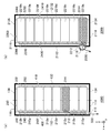
- FIGS. 6A and 6B show an outline of the discharge of the gas 500 in the storage battery module 1000.
- FIG. 6A is a cross-sectional view schematically showing the structure of the storage battery module 1000, and is a cross-sectional view in the same direction as FIG. 4.
- the first storage battery cells 210a to the eighth storage battery cells 210h are arranged from the lower side to the upper side.
- the front space 400 is arranged on the front side of these storage battery cells 210, and the front exhaust port 118 is provided on the front lower surface 114 in contact with the front space 400.
- the third storage battery cell 210c releases the high-temperature and high-pressure gas 500 from the positive electrode 212 side to the front space 400 via the front case 240 and the front lead plate 300.
- the gas 500 released into the front space 400 contacts the front surface 112. Since the front surface 112 is a metal plate, it absorbs heat from the gas 500 with which it comes into contact and radiates heat to the outside of the storage battery module 1000. As described above, the gas 500 is deprived of heat and cooled by the contact with the front surface 112. Further, since the cooled gas 500 is diffused in the front space 400, the pressure of the gas 500 decreases. Further, the gas 500 whose temperature and pressure have dropped is discharged to the outside of the storage battery module 1000 from the front exhaust port 118 provided below the front space 400.
- the volume of the fourth front space 400d is smaller than the volume of each of the first front space 400a to the third front space 400c. Therefore, the pressure in the fourth front space 400d is likely to be higher than the other pressures due to the gas 500 released from the storage battery cell 210. As a result, the third front partition 242c forming the fourth front space 400d is more easily damaged than the other front partition 242.
- the size of the fourth front exhaust port 118d provided in the fourth front space 400d is made larger than that of the other front exhaust ports 118. This suppresses an increase in pressure in the fourth front space 400d. That is, the smaller the size of the front space 400, the larger the area of the front exhaust port 118.
- the front exhaust port 118 is provided on the front upper surface 116, air may flow from the lower portion of the front space 400 that is not completely sealed. Since the inflowing air is discharged from the front exhaust port 118, a flow of air from the lower side to the upper side is generated in the front space 400. Such a flow of air supplies air to the sparks, so that high temperature combustion easily occurs. In the rear space 410 as well, as in the front space 400, the gas 500 is cooled, diffused, and released.
- 6B is a cross-sectional view schematically showing the structure of a storage battery module 2000 that is a comparison target of the storage battery module 1000 of FIG. 6A, and is a cross-sectional view in the same direction as FIG. 6A.
- 6A front surface 112 to front upper surface 116, rear surface 132 to rear upper surface 136, storage battery assembly 200 to negative electrode 214, front case 240, rear case 250, front lead plate 300, rear lead plate 302. ,
- the front exhaust port 2118 is provided in a portion of the front surface 2112 that is in contact with the front space 400 and that faces the positive electrode 2212 of the first storage battery cell 2210a.
- the first storage battery cell 2210a discharges the high temperature and high pressure gas 2500 from the positive electrode 2212 side to the front space 2400 via the front case 2240 and the front lead plate 2300.
- the gas 2500 released to the front space 2400 is released to the outside of the storage battery module 2000 from the front exhaust port 2118. That is, the gas 2500 is not cooled by contact with the front surface 2112. At that time, if a spark is generated, air is supplied to the spark, so that high temperature combustion is likely to occur.
- the gas 500 released from the storage battery cell 210 can be released to the outside from the exhaust port. Further, since the gas 500 in one space is discharged to the outside from one exhaust port, the gas 500 can be sufficiently discharged. Further, since the gas 500 is sufficiently released, it is possible to suppress the occurrence of high temperature combustion. Further, since the gas 500 in one space is discharged to the outside from one exhaust port, the inflow of air into the space can be suppressed. Moreover, since the inflow of air into the space is suppressed, the occurrence of high temperature combustion can be suppressed.
- the positive electrodes 212 have the same direction in different assemblies, a plurality of storage battery cells 210 facing the same direction can be classified into a plurality of assemblies. Further, since the space is divided into the first space and the second space, when the space is large, the small first space and second space can be formed. Further, since one exhaust port is provided for each of the small first space and second space, the gas 500 can be sufficiently discharged. Further, since one exhaust port is provided for each of the small first space and the second space, it is possible to suppress the inflow of air into the first space and the second space. Further, since the front surface 112 is a metal plate, the gas 500 can be cooled.
- the directions of the positive electrodes 212 in the different assemblies are opposite, a plurality of assemblies can be formed according to the directions of the plurality of storage battery cells 210.
- the space is divided into the first space and the second space, the first space and the second space can be formed on the opposite sides of the storage battery assembly 200.
- one exhaust port is provided for each of the first space and the second space, the gas 500 can be sufficiently discharged.
- one exhaust port is provided for each of the first space and the second space, it is possible to suppress the inflow of air into the first space and the second space.
- the front surface 112 and the rear surface 132 are metal plates, the gas 500 can be cooled.
- a storage battery module 1000 is a storage battery assembly in which a plurality of storage battery cells 210 each having a first electrode and a second electrode facing each other are arranged with the first electrodes facing the same direction. 200, a first surface of the storage battery assembly 200 that faces the plurality of first electrodes, a second surface of the storage battery assembly 200 that faces the plurality of second electrodes, and a first surface and a second surface.
- the structure 100 includes a third surface and a fourth surface that are opposed to each other with the storage battery assembly 200 sandwiched therebetween.
- a space surrounded by a plurality of surfaces of the storage battery assembly 200 on the side of the first electrode, the first surface, the third surface, and the fourth surface is formed.
- An exhaust port is provided on a portion of the first surface of the storage battery assembly 200 that is located on the third surface side of the end of the third surface on the third surface side, or on the third surface.
- One space has one exhaust port.
- a first assembly including a plurality of storage battery cells 210 in which the first electrode is the positive electrode 212 and the second electrode is the negative electrode 214, the first electrode is the positive electrode 212, and
- the second assembly includes a plurality of storage battery cells 210 in which the second electrode is the negative electrode 214.
- the space formed in the structure 100 includes a first space surrounded by a plurality of first electrode-side surfaces of the first assembly, a first surface, a third surface, and a fourth surface, and a space in the second assembly. It may include a second space surrounded by a plurality of first electrode-side surfaces, a first surface, a third surface, and a fourth surface.
- the exhaust port is a portion of the first surface located on the third surface side of the end of the first assembly on the third surface side of the first assembly in the first space, or the first exhaust gas disposed on the third surface. Mouth, and a second exhaust port arranged on the third surface of the second space on the third surface side of the end of the second assembly closer to the third surface than the storage battery cell 210. May include and.
- the storage battery module 1000 further includes a partition wall that partitions the first space and the second space.
- the first space may have one first exhaust port.
- the second space has one second exhaust port.
- the first surface is a metal plate.
- the storage battery assembly 200 includes a first assembly including a plurality of storage battery cells 210 in which the first electrode is the positive electrode 212 and the second electrode is the negative electrode 214, and the first electrode is the negative electrode 214, and The second electrode includes a plurality of storage battery cells 210 each having a positive electrode 212.
- the structure body 100 includes a first space surrounded by a plurality of first electrode-side surfaces of the first assembly, a first surface, a third surface, and a fourth surface, and a plurality of second spaces in the second assembly.
- a second space surrounded by the electrode-side surface, the second surface, the third surface, and the fourth surface is formed, and the structure 100 is the third surface-side end of the first aggregate in the first space.
- the first surface located on the third surface side of the storage battery cell 210 or the third exhaust surface is provided with the first exhaust port, and the storage battery cell at the third surface side end of the second assembly in the second space.
- a second exhaust port is provided on a portion of the second surface located closer to the third surface than 210, or on the third surface.
- the first space may have one first exhaust port.
- the second space has one second exhaust port.
- First and second sides are metal plates.
- the exhaust port consists of one opening.
- the exhaust port consists of multiple openings.
- a front space 400 and a rear space 410 are formed.
- only one of the front space 400 and the rear space 410 may be formed.
- a space suitable for arrangement can be formed.
- a plurality of front spaces 400 are arranged.
- the number of the front spaces 400 is not limited to this, and may be one, for example.
- the structure can be simplified when the size of the front space 400 is small. The same applies to the rear space 410.
- the front partition 242 and the rear partition 252 are made of resin or the like.
- the invention is not limited to this, and for example, the front partition wall 242 and the rear partition wall 252 formed of resin or the like may be reinforced by a metal plate or the like from the front space 400 or the rear space 410 side. According to the present modification, even if the pressure of the generated gas 500 increases, the front partition 242 and the rear partition 252 can be less likely to be damaged.
- the exhaust port is composed of one opening.
- the exhaust port may be configured by a plurality of openings.
- the openings are arranged adjacent to each other so that when the gas is discharged from one opening, the gas does not flow from the other opening. According to this modification, the degree of freedom of structure can be improved.
- thermal runaway (similar burning) of an adjacent battery due to high temperature combustion of the thermal runaway battery can be suppressed.
- 100 structure 110 front housing, 112 front surface (first surface), 114 front lower surface (third surface), 116 front upper surface (fourth surface), 118 front exhaust port (exhaust port), 130 rear housing, 132 rear surface (second surface), 134 rear lower surface (third surface), 136 rear upper surface (fourth surface), 138 rear exhaust port (exhaust port), 150 left side surface, 152 right side surface, 200 storage battery assembly (First aggregate, second aggregate)), 210 storage battery cell, 212 positive electrode (first electrode, second electrode), 214 negative electrode (first electrode, second electrode), 230 battery holder, 240 Front case, 242 front partition, 244 front case plate, 246 front recess, 250 rear case, 252 rear partition, 254 rear case plate, 256 rear recess, 300 front lead plate, 302 rear lead plate, 330 control board tray, 332 control board, 334 control board lid, 350 left side lid, 352 right side lid, 400 front space, 410 rear space, 1000 storage battery module.
Landscapes
- Chemical & Material Sciences (AREA)
- Chemical Kinetics & Catalysis (AREA)
- Electrochemistry (AREA)
- General Chemical & Material Sciences (AREA)
- Inorganic Chemistry (AREA)
- Battery Mounting, Suspending (AREA)
Abstract
Selon la présente invention, un corps de boîtier côté avant (110) comprend une surface avant (112), une surface inférieure avant (114), et une surface supérieure côté avant (116) faisant face à une pluralité d'électrodes positives (212) dans un cinquième agrégat de batteries de stockage (200e). Des troisièmes espaces avant (400c) sont formés dans le corps de boîtier côté avant (110), lesdits espaces étant entourés par les surfaces de la pluralité d'électrodes positives (212) dans le cinquième agrégat de batteries de stockage (200e), la surface avant (112), la surface inférieure côté avant (114) et la surface supérieure côté avant (116). Le corps de boîtier côté avant (110) comprend des troisièmes orifices d'échappement côté avant (118c) dans la partie de surface avant (112), qui est positionnée davantage vers le côté de la surface inférieure côté avant (114) qu'un élément de batterie de stockage (210) au niveau de l'extrémité du côté de la surface inférieure côté avant (114), dans le cinquième agrégat de batteries de stockage (200e) parmi les troisièmes espaces avant (400c), ou dans la surface inférieure avant (114). L'un des troisièmes espaces avant (400c) comprend l'un des troisièmes orifices d'échappement côté avant (118c).
Applications Claiming Priority (4)
| Application Number | Priority Date | Filing Date | Title |
|---|---|---|---|
| JP2018-231767 | 2018-12-11 | ||
| JP2018231767 | 2018-12-11 | ||
| JP2019045193A JP7270135B2 (ja) | 2018-12-11 | 2019-03-12 | 蓄電池モジュール |
| JP2019-045193 | 2019-03-12 |
Publications (1)
| Publication Number | Publication Date |
|---|---|
| WO2020121802A1 true WO2020121802A1 (fr) | 2020-06-18 |
Family
ID=71075963
Family Applications (1)
| Application Number | Title | Priority Date | Filing Date |
|---|---|---|---|
| PCT/JP2019/046101 Ceased WO2020121802A1 (fr) | 2018-12-11 | 2019-11-26 | Module de batterie de stockage |
Country Status (1)
| Country | Link |
|---|---|
| WO (1) | WO2020121802A1 (fr) |
Cited By (1)
| Publication number | Priority date | Publication date | Assignee | Title |
|---|---|---|---|---|
| JP2023544400A (ja) * | 2020-10-01 | 2023-10-23 | ビ-エイイ-・システムズ・コントロールズ・インコーポレイテッド | リチウムイオン電池パックにおける熱暴走伝播の軽減 |
Citations (6)
| Publication number | Priority date | Publication date | Assignee | Title |
|---|---|---|---|---|
| WO2011092773A1 (fr) * | 2010-01-29 | 2011-08-04 | パナソニック株式会社 | Module de pile |
| JP2015011956A (ja) * | 2013-07-02 | 2015-01-19 | ソニー株式会社 | 蓄電装置、蓄電システム、電子機器、電動車両および電力システム |
| JP2017091824A (ja) * | 2015-11-11 | 2017-05-25 | トヨタ自動車株式会社 | 電池ユニット |
| JP2018073560A (ja) * | 2016-10-26 | 2018-05-10 | 三洋電機株式会社 | 電源装置及びこれを用いる車両並びに蓄電装置 |
| JP2018073561A (ja) * | 2016-10-26 | 2018-05-10 | 三洋電機株式会社 | 電源装置 |
| WO2018123573A1 (fr) * | 2016-12-27 | 2018-07-05 | パナソニックIpマネジメント株式会社 | Module de batterie |
-
2019
- 2019-11-26 WO PCT/JP2019/046101 patent/WO2020121802A1/fr not_active Ceased
Patent Citations (6)
| Publication number | Priority date | Publication date | Assignee | Title |
|---|---|---|---|---|
| WO2011092773A1 (fr) * | 2010-01-29 | 2011-08-04 | パナソニック株式会社 | Module de pile |
| JP2015011956A (ja) * | 2013-07-02 | 2015-01-19 | ソニー株式会社 | 蓄電装置、蓄電システム、電子機器、電動車両および電力システム |
| JP2017091824A (ja) * | 2015-11-11 | 2017-05-25 | トヨタ自動車株式会社 | 電池ユニット |
| JP2018073560A (ja) * | 2016-10-26 | 2018-05-10 | 三洋電機株式会社 | 電源装置及びこれを用いる車両並びに蓄電装置 |
| JP2018073561A (ja) * | 2016-10-26 | 2018-05-10 | 三洋電機株式会社 | 電源装置 |
| WO2018123573A1 (fr) * | 2016-12-27 | 2018-07-05 | パナソニックIpマネジメント株式会社 | Module de batterie |
Cited By (2)
| Publication number | Priority date | Publication date | Assignee | Title |
|---|---|---|---|---|
| JP2023544400A (ja) * | 2020-10-01 | 2023-10-23 | ビ-エイイ-・システムズ・コントロールズ・インコーポレイテッド | リチウムイオン電池パックにおける熱暴走伝播の軽減 |
| JP7725577B2 (ja) | 2020-10-01 | 2025-08-19 | ビ-エイイ-・システムズ・コントロールズ・インコーポレイテッド | リチウムイオン電池パックにおける熱暴走伝播の軽減 |
Similar Documents
| Publication | Publication Date | Title |
|---|---|---|
| JP7605971B2 (ja) | ガス抜き経路を改善したバッテリーパック | |
| JP7233020B2 (ja) | 蓄電池モジュール | |
| JP7549049B2 (ja) | ガスベント流路を備えたバッテリーパック | |
| JP6004282B2 (ja) | 電池モジュール | |
| KR101776898B1 (ko) | 배터리 모듈 | |
| JP6779090B2 (ja) | 二次電池の熱暴走抑止システム | |
| US20230102399A1 (en) | Battery Module and Battery Pack Having the Same | |
| WO2023133722A1 (fr) | Compartiment de batterie, batterie, dispositif électrique, procédé et dispositif de préparation de batterie | |
| KR20230008110A (ko) | 전지, 전기 장치, 전지 제조 방법 및 장치 | |
| KR20120081198A (ko) | 전지 모듈 | |
| WO2021049315A1 (fr) | Bloc-batterie | |
| KR102860577B1 (ko) | 전지 모듈 및 이를 포함하는 전지팩 | |
| JP2023538320A (ja) | 電池モジュールおよびこれを含む電池パック | |
| KR20240023430A (ko) | 배터리, 전기 장치, 배터리를 제조하는 방법과 장치 | |
| KR20250120421A (ko) | 배터리 및 전기기기 | |
| KR20240012290A (ko) | 배터리 모듈 및, 이를 포함하는 배터리 팩 및 이를 포함하는 자동차 | |
| JP7270135B2 (ja) | 蓄電池モジュール | |
| WO2020189424A1 (fr) | Corps de support et module de batterie de stockage | |
| WO2022172742A1 (fr) | Module de batterie de stockage | |
| WO2020121802A1 (fr) | Module de batterie de stockage | |
| JP2024538190A (ja) | バッテリーパック、及びこれを含む自動車 | |
| US20230069871A1 (en) | Battery pack | |
| KR20240033834A (ko) | 배터리 팩 및 이를 포함하는 자동차 | |
| JP7300608B2 (ja) | 組電池 | |
| JP2025508461A (ja) | バッテリーパック |
Legal Events
| Date | Code | Title | Description |
|---|---|---|---|
| 121 | Ep: the epo has been informed by wipo that ep was designated in this application |
Ref document number: 19895706 Country of ref document: EP Kind code of ref document: A1 |
|
| NENP | Non-entry into the national phase |
Ref country code: DE |
|
| 122 | Ep: pct application non-entry in european phase |
Ref document number: 19895706 Country of ref document: EP Kind code of ref document: A1 |