WO2020121814A1 - Dispositif d'affichage d'image et système optique de relais - Google Patents
Dispositif d'affichage d'image et système optique de relais Download PDFInfo
- Publication number
- WO2020121814A1 WO2020121814A1 PCT/JP2019/046351 JP2019046351W WO2020121814A1 WO 2020121814 A1 WO2020121814 A1 WO 2020121814A1 JP 2019046351 W JP2019046351 W JP 2019046351W WO 2020121814 A1 WO2020121814 A1 WO 2020121814A1
- Authority
- WO
- WIPO (PCT)
- Prior art keywords
- optical system
- light
- unit
- optical
- light beam
- Prior art date
- Legal status (The legal status is an assumption and is not a legal conclusion. Google has not performed a legal analysis and makes no representation as to the accuracy of the status listed.)
- Ceased
Links
Images


Classifications
-
- G—PHYSICS
- G02—OPTICS
- G02B—OPTICAL ELEMENTS, SYSTEMS OR APPARATUS
- G02B27/00—Optical systems or apparatus not provided for by any of the groups G02B1/00 - G02B26/00, G02B30/00
- G02B27/02—Viewing or reading apparatus
-
- G—PHYSICS
- G09—EDUCATION; CRYPTOGRAPHY; DISPLAY; ADVERTISING; SEALS
- G09G—ARRANGEMENTS OR CIRCUITS FOR CONTROL OF INDICATING DEVICES USING STATIC MEANS TO PRESENT VARIABLE INFORMATION
- G09G3/00—Control arrangements or circuits, of interest only in connection with visual indicators other than cathode-ray tubes
- G09G3/02—Control arrangements or circuits, of interest only in connection with visual indicators other than cathode-ray tubes by tracing or scanning a light beam on a screen
-
- G—PHYSICS
- G09—EDUCATION; CRYPTOGRAPHY; DISPLAY; ADVERTISING; SEALS
- G09G—ARRANGEMENTS OR CIRCUITS FOR CONTROL OF INDICATING DEVICES USING STATIC MEANS TO PRESENT VARIABLE INFORMATION
- G09G3/00—Control arrangements or circuits, of interest only in connection with visual indicators other than cathode-ray tubes
- G09G3/20—Control arrangements or circuits, of interest only in connection with visual indicators other than cathode-ray tubes for presentation of an assembly of a number of characters, e.g. a page, by composing the assembly by combination of individual elements arranged in a matrix no fixed position being assigned to or needed to be assigned to the individual characters or partial characters
- G09G3/34—Control arrangements or circuits, of interest only in connection with visual indicators other than cathode-ray tubes for presentation of an assembly of a number of characters, e.g. a page, by composing the assembly by combination of individual elements arranged in a matrix no fixed position being assigned to or needed to be assigned to the individual characters or partial characters by control of light from an independent source
- G09G3/36—Control arrangements or circuits, of interest only in connection with visual indicators other than cathode-ray tubes for presentation of an assembly of a number of characters, e.g. a page, by composing the assembly by combination of individual elements arranged in a matrix no fixed position being assigned to or needed to be assigned to the individual characters or partial characters by control of light from an independent source using liquid crystals
-
- H—ELECTRICITY
- H04—ELECTRIC COMMUNICATION TECHNIQUE
- H04N—PICTORIAL COMMUNICATION, e.g. TELEVISION
- H04N5/00—Details of television systems
- H04N5/64—Constructional details of receivers, e.g. cabinets or dust covers
Definitions
- the present invention relates to an image display device and a relay optical system.
- Patent Document 1 There is known an image display device that is mounted on a user's head and irradiates a user's retina with scanned laser light to display an image on the retina (for example, Patent Document 1).
- a scanning system for scanning laser light and a driving circuit for the scanning system are mounted on the head of a user.
- the scanning system and the drive circuit are mounted on the user's head, the unit mounted on the user's head becomes large, which is a burden on the user.
- the relay optical system can be bent for convenience.
- the present invention has been made in view of the above problems, and an object of the present invention is to reduce the size of a unit worn on the head of a user. Alternatively, it is an object of the present invention to enable bending of the relay optical system when the unit mounted on the user's head is downsized.
- the present invention is detachable from a projection device that projects an image by scanning a light beam, and includes a plurality of units optically connected in multiple stages, and a light beam emitted by the projection device is incident on the first stage unit.
- a relay optical system in which the light beam emitted from the unit in the previous stage is incident on the unit in the next stage, and the light beam emitted from the unit in the final stage of the relay optical system is emitted to the retina of the user.
- An irradiation optical system is provided, and each unit of the relay optical system has an optical axis that is substantially parallel to each other and an optical axis is substantially parallel to each other.
- An image including a first optical component that converts a certain light beam, and a second optical component that converts a light beam emitted from the first optical component into a light beam whose optical axes converge with each other and each light beam is substantially parallel light It is a display device.
- the irradiation optical system may be configured to convert a light beam emitted by the relay optical system into a light beam whose optical axis converges into the eyeball of the user and is substantially parallel light.
- the scanning mechanism that scans the light beam in the projection device and the converging surface where the optical axis of the light beam converges in the eyeball may have a conjugate relationship via the relay optical system and the irradiation optical system. it can.
- the optical axis of the light beam emitted from the preceding unit may be converged between the preceding unit and the following unit.
- the converging surface on which the optical axis of the light beam converges before each unit and the converging surface on which the optical axis of the light beam converges after each unit may have a conjugate relationship through the respective units. it can.
- each unit of the plurality of units of the relay optical system may be a unit magnification optical system.
- At least one of the plurality of units of the relay optical system may not be a unit magnification optical system.
- the relay optical system may be configured to include a changing mechanism that changes an angle formed by optical axes of two adjacent units of the plurality of units.
- the relay optical system may include a changing mechanism that changes an angle formed by the optical axes of the first optical component and the second optical component in at least one unit of the plurality of units.
- the relay optical system may include an adjustment mechanism that adjusts a distance between the first optical component and the second optical component in at least one unit of the plurality of units.
- the relay optical system may be configured to include an adjusting mechanism that adjusts the intensity of the light beam passing through the relay optical system based on the intensity of the light beam passing through the relay optical system.
- At least one of the relay optical system and the irradiation optical system allows the light beam to pass through a converging surface on which an optical axis of the light beam converges before or after at least one unit of the plurality of units. It can be configured to include an aperture having an opening.
- the present invention provides a first optical component for entering and emitting a light beam, a second optical component for entering and emitting a light beam emitted by the first optical component, a first half mirror, and the first optical component.
- a second half mirror that emits a light beam that has passed through the first half mirror and reflects the light beam that is reflected by the first half mirror, and that transmits a light beam that is reflected by the first half mirror and that enters the second optical component.
- the first half mirror is a first plane orthogonal to the first optical axis.
- the second half mirror is tilted at a second angle having the same magnitude as the first angle, and the second half mirror is approximately half the first angle with respect to a second plane orthogonal to the first optical axis. And a mechanism for tilting at a third angle.
- the first optical component converts an incident light ray into a light ray whose optical axes are substantially parallel to each other and each light ray is a convergent light
- the second optical component outputs the first optical component. It is possible to adopt a configuration in which the rays to be converted are converted into rays in which the optical axes converge with each other and the rays are substantially parallel rays.
- the second half mirror may be configured to be tilted about a line segment including a position where a light beam located in the center among a plurality of light beams emitted from the first optical component enters.
- the first optical component converts incident light rays into light rays whose optical axes converge to each other and each light ray is substantially parallel light
- the second optical component emits light from the first optical component.
- a configuration can be adopted in which the light rays are converted into light rays whose optical axes are substantially parallel to each other and each light ray is a convergent light.
- the second half mirror may be configured to be tilted about a line segment including a position where the optical axes of the light rays emitted from the first optical component are substantially converged.
- the unit mounted on the user's head can be downsized.
- FIG. 1A is a block diagram of the image display device according to the first embodiment
- FIG. 1B is a diagram showing an irradiation optical system mounted on the head.
- FIG. 2 is a block diagram of the projection device in the first embodiment.
- FIG. 3A is a diagram showing a relay optical system in Example 1
- FIG. 3B is a diagram showing a unit.
- FIG. 4A and FIG. 4B are diagrams showing the irradiation optical system in the first embodiment.
- FIG. 5A and FIG. 5B are diagrams showing a relay optical system according to the first embodiment and its first modification.
- FIG. 6 is a diagram illustrating a final-stage unit in the second modification of the first embodiment.
- FIG. 7 is a diagram showing a bending mechanism between units in the second embodiment.
- FIG. 1A is a block diagram of the image display device according to the first embodiment
- FIG. 1B is a diagram showing an irradiation optical system mounted on the head.
- FIG. 2 is
- FIG. 8 is a perspective view showing a bending mechanism between units in the second embodiment.
- FIG. 9 is a diagram showing a bending mechanism between units in the first modification of the second embodiment.
- FIG. 10 is a diagram illustrating a relay optical system according to the third embodiment.
- FIG. 11 is a diagram illustrating a bending mechanism of the relay optical system according to the fourth embodiment.
- FIG. 12A and FIG. 12B are diagrams showing a relay optical system in Example 5 and Modification 1 thereof.
- FIG. 13 is a diagram illustrating an irradiation optical system according to Modification 2 of Example 5.
- FIG. 1A is a block diagram of the image display device according to the first embodiment.
- an image display device 100 is a Maxwell's image display device that directly irradiates a retina with a light beam such as a laser beam, and includes a relay optical system 10 and an irradiation optical system 20.
- the projection device 30 is a mobile device such as a smart phone or a pico projector having a pico projector function.
- the light beam 50 emitted from the projection device 30 is two-dimensionally scanned. When the scanned light beam 50 is projected on a wall or the like, an image is projected on the wall.
- the relay optical system 10 can be attached to and detached from the projection device 30 by the attachment/detachment mechanism 31.
- the scanned light beam 50 is incident on the relay optical system 10.
- the light beam 52 emitted from the relay optical system 10 enters the irradiation optical system 20.
- the irradiation optical system 20 irradiates the eyeball 70 of the user with the light ray 59 that reflects the light ray 52.
- Each optical axis of the light ray 59 converges on the lens 72 in the eyeball 70 or in the vicinity thereof, and then is irradiated on the retina 74.
- FIG. 1B is a diagram showing the irradiation optical system mounted on the head in the first embodiment.
- the irradiation optical system 20 is attached to the spectacle frame 78.
- the irradiation optical system 20 is mounted on the user's head 76.
- a projection device 30 is connected to the irradiation optical system 20 via the relay optical system 10.
- FIG. 2 is a block diagram of the projection device according to the first embodiment.
- the projection device 30 includes a scanning mechanism 32, a light source 33, a control circuit 34, and an input circuit 35.
- Image data is input to the input circuit 35 from a camera and/or a recording device inside or outside the projection device 30.
- the input circuit 35 converts the input image data and outputs it to the control circuit 34.
- the control circuit 34 controls the light source 33 and the scanning mechanism 32 based on the image data.
- a processor such as a CPU (Central Processing Unit) may perform processing in cooperation with a program.
- the control circuit 34 may be a circuit designed exclusively.
- the light source 33 emits, for example, a red laser light (wavelength: about 610 nm to 660 nm), a green laser light (wavelength: about 515 nm to 540 nm) and a blue laser light (wavelength: about 440 nm to 480 nm) as the light beam 51.
- a red laser light wavelength: about 610 nm to 660 nm
- a green laser light wavelength: about 515 nm to 540 nm
- a blue laser light wavelength: about 440 nm to 480 nm
- RGB red, green, blue
- the light source 33 is one light source and may emit laser light of a single wavelength.
- the scanning mechanism 32 is, for example, a MEMS (Micro Electro Mechanical Systems) and scans the light beam 51 two-dimensionally.
- the scanned light ray 50 has a diffused optical axis of the scanned light rays 50a, 50b and 50c and each light ray is substantially parallel.
- Rays 50a, 50b and 50c represent rays of scanned ray 50 at different times.
- the light rays 50a, 50b and 50c are emitted from the projection device 30.
- Each of the light rays 50a, 50b, and 50c is a substantially parallel light, but is a light that converges slightly.
- Focusing-free images are projected at arbitrary screen positions by gently diffusing each of the light rays 50a, 50b, and 50c from a distance of several 100 mm or more, which is a focus position.
- the scanning mechanism 32 may be a polygon mirror or the like.
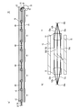
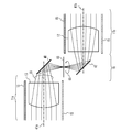
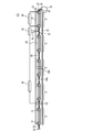
- FIG. 3A is a diagram showing a relay optical system in the first embodiment.
- the relay optical system 10 includes a plurality of multi-stage units 11.
- the plurality of units 11 are provided in the housing 15.
- the light beam 50 emitted from the scanning mechanism 32 enters the first-stage unit 11 of the relay optical system 10.
- the light beam emitted by the unit 11 of the previous stage enters the unit 11 of the next stage.
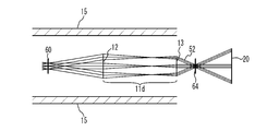
- the light beam 52 emitted from the unit 11 at the final stage enters the irradiation optical system 20.
- the light ray 59 emitted by the irradiation optical system 20 converges on a virtual converging surface 66 in the eyeball 70.
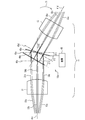
- Each unit 11 comprises optical components 12 and 13.
- a virtual converging surface 60 on which the scanned light beam converges exists between the unit 11 at the first stage and the unit 11 adjacent thereto.
- FIG. 3B is a diagram showing a unit.
- Rays 53a, 53b and 53c are rays of the scanned ray at different times.
- the straight line at the center indicates the optical axis of the ray
- the straight lines on both sides indicate the ends of the ray.
- the distance between the straight lines on both sides corresponds to the diameter of the light beam.
- the unit 11 includes optical components 12 and 13.
- the optical components 12 and 13 are, for example, convex lenses, which are infinite lenses. If the light ray 52 is of multiple colors (eg RGB), the optical components 12 and 13 should be a resin diffractive lens, a doubled, or a multi-group lens sized to be used in smart phone cameras to minimize chromatic aberration. Is preferred.
- the converging surface 60a is the converging surface 60 between the unit 11 at the preceding stage.
- the converging surface 60a corresponds to the scanning mechanism 32 of the projection device 30.
- the converging surface 60b is the converging surface 60 between the unit 11 of the next stage.
- the converging surface 60b corresponds to the converging surface with the irradiation optical system 20 or the converging surface 66 in the eyeball 70.
- the optical axes of the scanned light rays 53a, 53b and 53c and the optical axes of 55a, 55b and 55c converge, and the respective light rays 53a, 53b and 53c and 55a, 55b and 55c are substantially parallel.
- the converging surfaces 60a and 60b are in a conjugate relationship with each other through the unit 11, for example, a conjugate relationship of approximately equal magnification.
- the optical axes of the light rays 53a, 53b and 53c entering the optical component 12 from the converging surface 60a are diffused with each other and the respective light rays 53a, 53b and 53c are substantially parallel light.
- the optical component 12 converts the light rays 53a, 53b and 53c into the light rays 54a, 54b and 54c.
- the optical axes of the light rays 54a, 54b, and 54c are substantially parallel to each other, and the light rays 54a, 54b, and 54c are converged light up to the focal point 61 immediately after exiting the optical component 12.
- Each ray 54a, 54b and 54c forms a focal point 61 between the optical components 12 and 13.
- optical axes of the light rays 54a, 54b and 54c incident on the optical component 13 are substantially parallel to each other and each light ray 54a, 54b and 54c is diffuse light.
- Optical component 13 transforms rays 54a, 54b and 54c into rays 55a, 55b and 55c.
- the optical axes of the light rays 55a, 55b and 55c converge with each other and each light ray 55a, 55b and 55c is substantially parallel light.
- the relay optical system 10 can emit the light beam 52 at the same viewing angle as that of the light beam 50 emitted by the projection device 30.
- the projection device 30 when the projection device 30 is stored in the chest pocket of the user, the projection device 30 can be connected to the head irradiation optical system 20 by using the relay optical system 10 having a length of about 30 cm.
- the number of units 11 is about five. The number and length of the units 11 can be set appropriately.
- FIGS. 4A and 4B are diagrams showing the irradiation optical system in the first embodiment.
- FIG. 4B is an enlarged view of FIG.
- the irradiation optical system 20 includes an optical system 21 and an optical system 25.
- the optical system 21 includes curved mirrors 22 and 24 and a plane mirror 23.
- the reflective surfaces of the curved mirrors 22 and 24 are curved surfaces such as free curved surfaces.
- the outer shape of the curved mirror 22 is larger than that of the curved mirror 24.
- the reflecting surface of the plane mirror 23 is substantially flat.
- the optical system 25 includes a curved mirror 26 and a curved mirror 28.
- the reflecting surfaces of the curved mirrors 26 and 28 are curved surfaces such as free curved surfaces.
- the outer shape of the curved mirror 28 is larger than that of the curved mirror 26.
- the curved mirrors 22 and 28 have the same curved shape, for example.
- the curved mirrors 24 and 26 have the same curved shape, for example. Accordingly, the curved mirrors 22 and 28 and the curved mirrors 24 and 26 have, for example, substantially the same focal length.
- the curved mirrors 22 and 28 are arranged at positions symmetrical with respect to the convergent surface 65, and the curved mirrors 24 and 26 are arranged at symmetrical positions with respect to the convergent surface 65.
- the converging surface 64 is a converging surface between the relay optical system 10 and the irradiation optical system 20, and the converging surface 66 is a converging surface within the eyeball 70.
- the optical axes of the light rays 52a, 52b, and 52c emitted from the relay optical system 10 converge on the converging surface 64.
- Each of the light rays 52a, 52b and 52c is substantially parallel light.
- the optical axes of the light rays 56a, 56b and 56c reflected by the curved mirror 22 are substantially parallel to each other and the respective light rays 56a, 56b and 56c are convergent light.
- a plane mirror 23 is provided for the purpose of bending the optical path.
- the optical axes of the light rays 57a, 57b and 57c reflected by the curved mirror 24 are converged with each other and the respective light rays 57a, 57b and 57c are substantially parallel light rays.
- the rays 57a, 57b and 57c converge at the converging surface 65.
- the optical axes of the light rays 58a, 58b and 58c reflected by the curved mirror 26 are substantially parallel to each other, and the respective light rays 58a, 58b and 58c are convergent light.
- the light rays 58a, 58b and 58c are focused at the focal point 67b.
- the optical axes of the light rays 59a, 59b and 59c reflected by the curved mirror 28 converge with each other and the respective light rays 59a, 59b and 59c are substantially parallel light.
- the optical axes of the rays 59a, 59b and 59c converge at a converging plane 66 in the eye 70 and each ray 59a, 59b and 59c is substantially focused at the retina 74.
- the converging surfaces 64 and 65 are in a unity conjugate relationship via the optical system 21, and the converging surfaces 65 and 66 are in a unity conjugate relationship via the optical system 25. As a result, the converging surfaces 64 and 66 have a unity-scale conjugate relationship. Since the scanning mechanism 32 and the converging surface 64 are in the same-magnification conjugate relationship via the relay optical system 10, the scanning mechanism 32 and the converging surface 66 are in the same-magnification conjugate relationship via the relay optical system 10 and the irradiation optical system 20. Becomes Thereby, the image projected by the projection device 30 can be projected on the retina 74.
- the scanning mechanism and its drive circuit are mounted on the head unit to be mounted on the user's head as in Patent Document 1, the head unit becomes large.
- countermeasures for radiation of electromagnetic waves from the head unit and/or countermeasures for heat radiation are taken. This further increases the size of the head unit and increases the number of parts. Therefore, the manufacturing process is lengthened and complicated. Further, the scanning mechanism and the driving circuit will be uniquely designed. This increases development costs.
- the light source on the head unit makes the head unit even larger. Therefore, if the light source is mounted on a part other than the head unit, the light source and the head unit are connected by an optical fiber. In this case, it becomes difficult to attach and detach the head unit and the unit equipped with the light source.
- the projection device 30 that projects an image by scanning the light beam 50 is used.
- the relay optical system 10 is attachable to and detachable from the projection device 30, and includes a plurality of units 11 that are optically connected in multiple stages.
- the light beam 50 emitted from the projection device 30 is incident on the first stage unit, and The emitted light beam is incident on the next unit.
- the irradiation optical system 20 is attached to the user's head 76, and irradiates the user's retina 74 with the light beam 52 emitted by the final stage unit 11 of the relay optical system 10.
- Each unit of the relay optical system 10 includes an optical component 12 (first optical component) and an optical component 13 (second optical component).
- the optical component 12 converts light rays 53a, 53b, and 53c whose optical axes are diffused into each other and whose light rays are substantially parallel to each other into light rays 54a, 54b, and 54c whose optical axes are substantially parallel and whose light rays are convergent light. To do.
- the optical component 13 converts the light rays 54a, 54b, and 54c emitted from the optical component 12 into light rays 55a, 55b, and 55c whose optical axes are converged to each other and which are substantially parallel rays.
- the light ray 50 emitted from the projection device 30 can be applied to the retina 74 as the light ray 59.
- the scanning mechanism 32 or the like may not be attached to the head 76. Therefore, the unit mounted on the head 76 can be downsized. Further, since no countermeasure against electromagnetic radiation and/or heat radiation is required, the unit mounted on the head 76 can be made smaller. Since the number of parts can be reduced, the manufacturing process can be shortened and simplified. Further, since the existing projection device 30 is used as the scanning mechanism and the driving circuit, the development cost can be suppressed. Further, since the light source 33 is provided in the projection device 30, the relay optical system 10 and the projection device 30 can be attached and detached. The optical axes of the light rays being substantially parallel and the light rays being substantially parallel light may be substantially parallel light and substantially parallel light so that the image emitted by the projection device 30 can be projected on the retina 74.
- the irradiation optical system 20 converts the light ray 52 emitted from the relay optical system 10 into a light ray 59 whose optical axis is converged into the eyeball 70 of the user and is substantially parallel light. Thereby, an image can be projected on the user's retina.
- the scanning mechanism 32 that scans the light beam in the projection device 30 and the converging surface 66 where the optical axis of the light beam converges in the eyeball 70 are in a conjugate relationship via the relay optical system 10 and the irradiation optical system 20. Thereby, an image can be projected on the user's retina.
- the optical axis of the light beam emitted by the unit 11 in the previous stage converges between the unit 11 in the previous stage and the unit 11 in the next stage. Thereby, the light beam can be relayed by the unit 11.
- the converging surface 60a where the optical axis of the light beam converges in front of each unit 11 and the converging surface 60b where the optical axis of the light beam converges after each unit 11 have a conjugate relationship via each unit 11. Thereby, the light beam can be relayed by the unit 11.
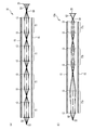
- FIG. 5A and FIG. 5B are diagrams showing a relay optical system according to the first embodiment and its first modification.
- each unit 11 of the relay optical system 10 is a unit-magnification optical system.
- the converging surface 64 between the relay optical system 10 and the irradiation optical system 20 and the scanning mechanism 32 have a conjugate relationship of 1 ⁇ through the relay optical system 10.
- the relay optical system 10a includes a plurality of units 11a, 11b and 11c.
- the units 11a, 11b and 11c include optical components 12 and 13, respectively.
- the unit 11b is a unit magnification optical system, but the units 11a and 11c are not unit magnification optical systems.
- the unit 11a is a 1/2 ⁇ optical system, and the unit 11c is a 2 ⁇ optical system.
- the unit 11a doubles the viewing angle and doubles the diameter of the light beam.
- the unit 11c doubles the viewing angle and halves the diameter of the light beam.
- the scanning mechanism 32 and the converging surface 64 have a unity-scale conjugate relationship via the relay optical system 10.
- the other configuration is the same as that of the first embodiment, and the description is omitted.
- each unit 11 of the plurality of units 11 of the relay optical system 10 is a unit magnification optical system. This facilitates the design of the relay optical system 10.
- At least one of the plurality of units 11a, 11b, and 11c of the relay optical system 10 is not a unit magnification optical system.
- the distance between the units 11a, 11b and 11c and the length of the units 11a, 11b and 11c can be freely set.
- the number of units 11a, 11b, and 11c in the first modification of the first embodiment can be smaller than that in the first embodiment.
- other optical components for example, a plane mirror or a half mirror
- FIG. 6 is a diagram illustrating a final-stage unit in the second modification of the first embodiment.
- the unit 11d at the final stage is not an equal-magnification optical system, but an enlargement optical system, for example.
- NA of the optical components 12 and/or 13 is different from that of other units.
- the units 11 other than the unit 11d at the final stage are equal-magnification optical systems.
- the beam diameter of the light beam 50 emitted from the projection device 30 is 1.0 mm and the viewing angle is 40°, and the unit 11d is a double optical system
- the beam diameter of the light beam 52 emitted from the relay optical system 10 is The viewing angle can be set to about 80° with a thickness of 0.5 mm.
- the other configuration is the same as that of the first embodiment, and the description is omitted.
- the relay optical system 10 may be a unit-magnification optical system, as in the first embodiment and its first modification. As in the second modification of the first embodiment, the relay optical system 10 may not be a unity magnification optical system. Similarly, the irradiation optical system 20 may be a 1 ⁇ optical system, and the relay optical system 10 may not be a 1 ⁇ optical system.
- Example 2 is an example in which the relay optical system 10 can be bent between the units 11.
- FIG. 7 is a diagram showing a bending mechanism between units in the second embodiment
- FIG. 8 is a perspective view showing a bending mechanism between units in the second embodiment.
- Each line of ray 55 in FIG. 7 represents the optical axis of the ray of the scanned ray at different times.
- Ray 55 in FIG. 8 represents a bundle of scanned rays.
- a bending mechanism 16 is provided between the unit 11a at the front stage and the unit 11b at the rear stage.
- the bending mechanism 16 has plane mirrors 40 and 42.
- the light ray 55 emitted from the optical component 13 of the unit 11a is reflected by the plane mirror 40.
- the optical axis of the light ray 55 converges on the converging surface 68.
- the optical axes of the rays 55 then diffuse into each other and are reflected by the plane mirror 42.
- the light ray 55 then enters the optical component 12 of the unit 11b.
- the plane mirror 40 is inclined 45° with respect to the optical axis 41a of the unit 11a
- the plane mirror 42 is inclined 45° with respect to the optical axis 41b of the unit 11b.
- the bending mechanism 16 rotates the unit 11b and the plane mirror 42 with respect to the unit 11a and the plane mirror 40 about the central axis of the converging surface 68. Thereby, the units 11a and 11b can be bent.
- the rotation angle of the arrow 69 can be set arbitrarily, but it is preferable that the rotation angle is at intervals of 90° in order to prevent the image from tilting. For example, a rotation restraint mechanism is provided for every 90° of rotation angle.
- the other configuration is the same as that of the first embodiment, and the description is omitted.
- FIG. 9 is a diagram showing a bending mechanism between units in the first modification of the second embodiment.
- a bending mechanism 18 is provided between the unit 11a at the front stage and the unit 11b at the rear stage.
- the bending mechanism 18 has half mirrors 44 and 46.
- the light ray 55 emitted from the optical component 13 of the unit 11 a passes through the half mirror 44 and is reflected by the half mirror 46. After that, the light ray 55 is reflected by the half mirror 44, passes through the half mirror 46, and enters the optical component 12 of the unit 11b.
- the plane 45a orthogonal to the optical axis 41a and the plane 45b orthogonal to the optical axis 41b are substantially parallel to each other.
- the optical axis 41b of the unit 11b is inclined by the angle ⁇ 0 with respect to the optical axis 41a of the unit 11a as indicated by the arrow 69
- the half mirror 44 is inclined by the angle ⁇ 1 in the same direction as the arrow 69 with respect to the plane 45a.
- the half mirror 46 is tilted by an angle ⁇ 2 in the direction opposite to the arrow 69 with respect to the plane 45b.
- the angle ⁇ 1 is approximately the angle ⁇ 0, and the angle ⁇ 2 is approximately half the angle ⁇ 0. Thereby, the units 11a and 11b can be bent at an arbitrary angle.
- the other configuration is the same as that of the first embodiment, and the description is omitted.
- the relay optical system 10 includes the bending mechanisms 16 and 18 (changed) that change the angle formed by the optical axes 41a and 41b of two adjacent units 11a and 11b of the plurality of units 11. Mechanism). Thereby, the shape of the relay optical system 10 can be arbitrarily changed.
- FIG. 10 is a diagram showing a relay optical system according to the third embodiment.
- the relay optical system 10b includes a control unit 80, a half mirror 81, a detector 82, a dimming adjustment mechanism 83, dimming filters 84a and 84b, and a focus adjustment mechanism 86.
- the half mirror 81 separates a part of the light ray 54 passing through the relay optical system 10 as a light ray 85.
- the detector 82 detects the intensity of the light ray 85.
- the control unit 80 controls the dimming adjustment mechanism 83 based on the output signal of the detector 82.
- the detector 82 can detect the intensity of the light ray 54 passing through the relay optical system 10b by detecting the intensity of the light ray 85.
- the control unit 80 causes the dimming adjustment mechanism 83 to dimm the light beam 54 based on the intensity of the light beam 54 detected by the detector 82.
- the dimming adjustment mechanism 83 is, for example, a liquid crystal filter, and can change the dimming rate of the light ray 54. Further, the light ray 54 can be blocked.
- the dimming adjustment mechanism 83 adjusts the intensity of the light beam 54 so that the intensity of the light beam 54 passing through the relay optical system 10b does not exceed a predetermined value. With this, the intensity of the light beam 52 emitted from the relay optical system 10b can be appropriately adjusted, and thus the safety of the image display device can be improved.
- the control unit 80 and the dimming adjustment mechanism 83 may block the light beam 54 when the intensity of the light beam 54 exceeds a predetermined level. Further, the control unit 80 and the dimming adjustment mechanism 83 can also make the intensity of the light beam 54 almost constant by feedback controlling.
- the position where the detector 82 detects the intensity of the light beam 54 can be set to any position in the relay optical system 10b.
- the position where the dimming adjustment mechanism 83 is provided can be set to any position in the relay optical system 10b.
- the neutral density filters 84a and 84b have a constant neutral density ratio. Since the intensity of the light ray 54 can be limited also by providing one or a plurality of neutral density filters 84a and 84b, the safety of the image display device can be improved also by the neutral density filters 84a and 86b.
- the neutral density filters 84a and 84b can be provided between the units 11 and at arbitrary positions within the unit 11. Depending on the intensity of the light beam 54, the size of the relay optical system 10b, and the like, both the dimming adjustment mechanism and the dimming filter may be installed, or either one may be installed.
- the focus adjustment mechanism 86 adjusts the distance between the optical components 12 and 13.
- the light beam 50 emitted from the projection device 30 is substantially parallel light, but is focused at a distance (for example, 50 cm) equal to or greater than that of the relay optical system 10b.
- the focusing distance may vary depending on the projection device 30.
- a focus adjustment mechanism 86 that adjusts the distance between the optical components 12 and 13 in at least one unit of the plurality of units 11 is provided. This allows the light rays to be focused on the retina 74.
- the other configuration is the same as that of the first embodiment, and the description is omitted.
- the dimming adjustment mechanism 83, the dimming filters 84a and 84b, and the focus adjustment mechanism 86 can be provided in the first and second embodiments and their modifications.
- Example 4 is an example in which the relay optical system can be bent between the optical components 12 and 13 provided in one unit 11.
- FIG. 11 is a diagram illustrating a bending mechanism of the relay optical system according to the fourth embodiment.
- a bending mechanism 18a including half mirrors 44a and 46a arranged between the optical components 12 and 13 provided in one unit 11 and a mechanism 48 for tilting the half mirrors 44a and 46a. Equipped with.
- Light rays 54a to 54c emitted from the optical component 12 pass through the half mirror 44a and are reflected by the half mirror 46a. After that, the light rays 54a to 54c are reflected by the half mirror 44a, transmitted through the half mirror 46a, and incident on the optical component 13.
- the mechanism 48 sets the half mirror 44a at an angle ⁇ 0 in the same direction as the arrow 71 with respect to the plane 45c.
- the angle ⁇ 1 of substantially the same size is tilted.
- the mechanism 48 tilts the half mirror 46a with respect to the plane 45d in the direction opposite to the arrow 71 by an angle ⁇ 2 that is approximately half the angle ⁇ 0.
- the mechanism 48 tilts the half mirror 46a in the same direction as the arrow 71 with respect to the plane 45e orthogonal to the optical axis 41c by an angle ⁇ 3 that is approximately half the angle ⁇ 0.
- the optical component 12 and the optical component 13 can be bent at an arbitrary angle in one unit 11.
- a gear mechanism or a link mechanism can be used as the mechanism 48.
- the other configuration is the same as that of the first embodiment, and the description is omitted.
- the relay optical system includes the half mirrors 44a and 46a and the mechanism 48, and the bending mechanism 18a that changes the angle formed by the optical axis 41c of the optical component 12 and the optical axis 41d of the optical component 13 in one unit 11. (Change mechanism).
- the shape of the relay optical system can be arbitrarily changed.
- the bending mechanism 18 may include a mechanism 48 for inclining the half mirrors 44 and 46, as in the fourth embodiment.
- the mechanism 48 causes the half mirror 44 to form an angle substantially the same as the angle ⁇ 0 with respect to a plane orthogonal to the optical axis 41a. Tilt.
- the mechanism 48 tilts the half mirror 46 at an angle approximately half the angle ⁇ 0 with respect to the plane orthogonal to the optical axis 41a.
- the relay optical system is bent between the adjacent units 11a and 11b as an example.
- the present invention is not limited to this case, and the relay optical system may be bent between the optical components 12 and 13 in one unit 11 as in the fourth embodiment.
- the optical component 12 converts incident light rays 53a to 53c into light rays 54a to 54c whose optical axes are substantially parallel to each other and which are convergent light rays.
- the optical component 13 converts the light beams 54a to 54c emitted from the optical component 12 into light beams 55a to 55c whose optical axes are converged with each other and which are substantially parallel lights.
- the half mirrors 44 and 46 are arranged between the optical component 13 of the unit 11a and the optical component 12 of the unit 11b as in the first modification of the second embodiment, the half mirrors 44 and 46 have substantially parallel light. Rays of light are incident.
- the light rays that have passed through the half mirrors 44 and 46 without being reflected may be applied to the user's retina.
- the optical path length differs from that of the light ray traveling in the optical path of.
- the light rays incident on the half mirrors 44 and 46 are substantially parallel light, the light rays transmitted without being reflected by the half mirrors 44 and 46 are focused near the user's retina, and as a result, the light rays are transmitted to the user's retina.
- the desired image may not be projected well.
- the half mirrors 44a and 46a are arranged between the optical component 12 and the optical component 13 of one unit 11, the half mirrors 44a and 46a have converged light or diffused light rays. Is incident. A light ray that travels through a regular optical path that passes through the half mirror 44a, is reflected by the half mirror 46a, is then reflected by the half mirror 44a, and is transmitted through the half mirror 46a; The optical path length differs from that of the light ray traveling in the optical path of.
- the light rays incident on the half mirrors 44a and 46a are convergent light or diffused light, the light rays transmitted without being reflected by the half mirrors 44a and 46a are suppressed from being focused near the user's retina, As a result, a desired image can be favorably projected on the user's retina.
- the half mirror 46a be tilted about a line segment including a position where a light beam 54b located at the center of a plurality of light beams emitted from the optical component 12 is incident.
- the half mirror 46 is tilted depending on whether the optical axis 41d of the optical component 13 is tilted in the direction of the arrow 71 with respect to the optical axis 41c of the optical component 12 or the direction opposite to the arrow 71. Since it is inclined symmetrically, the relay optical system is easily bent.
- the light beam positioned in the center of the plurality of light beams emitted by the optical component 12 is a light beam positioned in the center of the image projected by the two-dimensionally scanned light beam, and is a light beam positioned in the center of the scanning range. is there.
- the half mirror 46 is the unit 11a. It is preferable that the optical component 13 is tilted about a line segment including a position where the optical axis of the light beam emitted from the optical component 13 is substantially converged. As a result, the expansion of the device size in the radial direction can be suppressed.
- each unit 11 of the relay optical system 10c is a unit magnification optical system.
- the unit 11b of the relay optical system 10d is a unit magnification optical system, but the units 11a and 11c are not unit magnification optical systems.
- the unit 11c is a 1/2 optical system, and the unit 11c is a 2 optical system.
- the optical axis of the light beam converges between the units 11 to 11c.
- An aperture 90 is provided having an opening through which the light rays pass.
- FIG. 13 is a diagram showing an irradiation optical system in Modification 2 of Example 5.
- the light rays pass through the converging surface where the optical axes of the light rays 52a to 52c emitted from the unit 11 at the final stage of the relay optical system 10 converge.
- An aperture 90 having an opening is provided.
- the aperture 90 may be provided on all the converging surfaces on which the optical axes of the light rays converge before or after the unit 11, but it may be provided on at least one converging surface.
- the aperture 90 may be an aperture having a fixed aperture diameter through which a light beam passes, or an aperture whose aperture diameter can be adjusted.
- At least one of the relay optical system and the irradiation optical system is a convergent optical axis of the light beam before or after at least one unit 11 among the plurality of units 11. It is preferable to provide an aperture 90 having an opening through which light rays pass.
- the aperture 90 allows the beam diameter of the light beam to be adjusted.
- the beam diameter of the light beam 50 emitted from the projection device 30 may be about 1 mm in diameter.
- the beam diameter of the light beam incident on the user's cornea tends to expand.
- the beam diameter of the light beam incident on the user's cornea be 0.8 mm or less. Therefore, in the fifth embodiment, the aperture 90 is arranged on the converging surface on which the optical axes of the light rays converge. Thereby, the beam diameter of the light beam can be adjusted, and the beam diameter of the light beam when entering the cornea of the user can be adjusted to an appropriate size to project a focus-free image.
Landscapes
- Engineering & Computer Science (AREA)
- Physics & Mathematics (AREA)
- General Physics & Mathematics (AREA)
- Computer Hardware Design (AREA)
- Theoretical Computer Science (AREA)
- Chemical & Material Sciences (AREA)
- Crystallography & Structural Chemistry (AREA)
- Multimedia (AREA)
- Signal Processing (AREA)
- Optics & Photonics (AREA)
Abstract
La présente invention concerne un dispositif d'affichage d'image comprenant : un système optique de relais qui peut être fixé à un dispositif de projection et détaché d'un dispositif de projection qui projette une image par balayage de faisceaux lumineux, et qui comprend une pluralité d'unités qui sont reliées optiquement dans de multiples étages, les faisceaux lumineux émis par le dispositif de projection étant incidents sur l'unité du premier étage et les faisceaux lumineux émis par une unité dans un étage précédent étant incidents sur l'unité de l'étage suivant ; et un système optique d'orientation de faisceau qui est monté sur la tête d'un utilisateur et dirige les faisceaux lumineux émis par l'unité de l'étage final du système optique de relais vers la rétine de l'utilisateur, chaque unité dans le système optique de relais comprenant un premier composant optique qui convertit des faisceaux lumineux incidents, dans lesquels les axes optiques des faisceaux s'écartent l'un de l'autre et les faisceaux sont chacun parallèles, en des faisceaux lumineux, dans lesquels les axes optiques des faisceaux sont sensiblement parallèles et les faisceaux sont chacun convergents, et un second composant optique qui convertit les faisceaux lumineux émis par le premier composant optique en faisceaux lumineux dans lesquels les axes optiques des faisceaux convergent et les faisceaux sont chacun parallèles.
Applications Claiming Priority (4)
| Application Number | Priority Date | Filing Date | Title |
|---|---|---|---|
| JP2018-231712 | 2018-12-11 | ||
| JP2018231712 | 2018-12-11 | ||
| JP2019076662A JP2020095237A (ja) | 2018-12-11 | 2019-04-12 | 画像表示装置および中継光学系 |
| JP2019-076662 | 2019-04-12 |
Publications (1)
| Publication Number | Publication Date |
|---|---|
| WO2020121814A1 true WO2020121814A1 (fr) | 2020-06-18 |
Family
ID=71075967
Family Applications (1)
| Application Number | Title | Priority Date | Filing Date |
|---|---|---|---|
| PCT/JP2019/046351 Ceased WO2020121814A1 (fr) | 2018-12-11 | 2019-11-27 | Dispositif d'affichage d'image et système optique de relais |
Country Status (1)
| Country | Link |
|---|---|
| WO (1) | WO2020121814A1 (fr) |
Cited By (1)
| Publication number | Priority date | Publication date | Assignee | Title |
|---|---|---|---|---|
| CN113485061A (zh) * | 2021-06-30 | 2021-10-08 | 歌尔光学科技有限公司 | 投影光机 |
Citations (5)
| Publication number | Priority date | Publication date | Assignee | Title |
|---|---|---|---|---|
| JPH0339925A (ja) * | 1989-02-21 | 1991-02-20 | United Technol Corp <Utc> | デイスプレイ装置に使用のヘルメットへの取着装置 |
| JPH06281878A (ja) * | 1993-03-26 | 1994-10-07 | Canon Inc | 複眼式画像表示装置 |
| JP2003315726A (ja) * | 2002-04-22 | 2003-11-06 | Brother Ind Ltd | 画像表示装置 |
| WO2004029693A1 (fr) * | 2002-09-24 | 2004-04-08 | Nikon Corp | Unite d'affichage d'images et systeme optique de projection |
| JP2018063365A (ja) * | 2016-10-13 | 2018-04-19 | 株式会社Qdレーザ | 画像投影装置 |
-
2019
- 2019-11-27 WO PCT/JP2019/046351 patent/WO2020121814A1/fr not_active Ceased
Patent Citations (5)
| Publication number | Priority date | Publication date | Assignee | Title |
|---|---|---|---|---|
| JPH0339925A (ja) * | 1989-02-21 | 1991-02-20 | United Technol Corp <Utc> | デイスプレイ装置に使用のヘルメットへの取着装置 |
| JPH06281878A (ja) * | 1993-03-26 | 1994-10-07 | Canon Inc | 複眼式画像表示装置 |
| JP2003315726A (ja) * | 2002-04-22 | 2003-11-06 | Brother Ind Ltd | 画像表示装置 |
| WO2004029693A1 (fr) * | 2002-09-24 | 2004-04-08 | Nikon Corp | Unite d'affichage d'images et systeme optique de projection |
| JP2018063365A (ja) * | 2016-10-13 | 2018-04-19 | 株式会社Qdレーザ | 画像投影装置 |
Cited By (2)
| Publication number | Priority date | Publication date | Assignee | Title |
|---|---|---|---|---|
| CN113485061A (zh) * | 2021-06-30 | 2021-10-08 | 歌尔光学科技有限公司 | 投影光机 |
| CN113485061B (zh) * | 2021-06-30 | 2022-07-22 | 歌尔光学科技有限公司 | 投影系统 |
Similar Documents
| Publication | Publication Date | Title |
|---|---|---|
| CN110753876B (zh) | 图像投影装置 | |
| CN110709755B (zh) | 图像投影装置 | |
| JP6565407B2 (ja) | 画像表示装置 | |
| CN109804296B (zh) | 图像投影装置 | |
| US11573423B2 (en) | Image display apparatus and head-mounted display | |
| JP6820502B2 (ja) | 画像表示装置 | |
| WO2020121814A1 (fr) | Dispositif d'affichage d'image et système optique de relais | |
| JP2020177221A (ja) | 遠視点空中像投射装置 | |
| WO2022244571A1 (fr) | Dispositif de balayage optique | |
| WO2023090173A1 (fr) | Dispositif de projection d'image | |
| JP2016224345A (ja) | 画像表示装置 | |
| JP6860258B2 (ja) | 画像中継装置及び画像投影システム | |
| JP2020095237A (ja) | 画像表示装置および中継光学系 | |
| JP7050292B2 (ja) | 画像投影装置 | |
| JP2020173398A (ja) | 中継光学部品及び画像表示装置 | |
| JP2020204669A (ja) | 画像表示装置 | |
| JP2020173397A (ja) | 中継光学部品及び画像表示装置 | |
| JP7712466B2 (ja) | 複数のレーザの可変ビーム拡張を用いたディスプレイシステム | |
| JP4423941B2 (ja) | 画像表示装置 | |
| WO2025115408A1 (fr) | Dispositif de projection d'image | |
| CN120883116A (zh) | 图像投影装置以及图像投影装置的制造方法 | |
| WO2020059618A1 (fr) | Dispositif d'affichage tête haute | |
| JP2016151601A (ja) | 画像表示装置 | |
| JP2021081509A (ja) | 画像投影装置 | |
| JP2017151145A (ja) | 光源装置および投影装置 |
Legal Events
| Date | Code | Title | Description |
|---|---|---|---|
| 121 | Ep: the epo has been informed by wipo that ep was designated in this application |
Ref document number: 19896921 Country of ref document: EP Kind code of ref document: A1 |
|
| NENP | Non-entry into the national phase |
Ref country code: DE |
|
| 122 | Ep: pct application non-entry in european phase |
Ref document number: 19896921 Country of ref document: EP Kind code of ref document: A1 |