WO2020121843A1 - Dispositif de réception, procédé de réception, dispositif de transmission, et procédé de transmission - Google Patents
Dispositif de réception, procédé de réception, dispositif de transmission, et procédé de transmission Download PDFInfo
- Publication number
- WO2020121843A1 WO2020121843A1 PCT/JP2019/046728 JP2019046728W WO2020121843A1 WO 2020121843 A1 WO2020121843 A1 WO 2020121843A1 JP 2019046728 W JP2019046728 W JP 2019046728W WO 2020121843 A1 WO2020121843 A1 WO 2020121843A1
- Authority
- WO
- WIPO (PCT)
- Prior art keywords
- transmission
- signal
- demodulation unit
- control information
- time division
- Prior art date
- Legal status (The legal status is an assumption and is not a legal conclusion. Google has not performed a legal analysis and makes no representation as to the accuracy of the status listed.)
- Ceased
Links
Images





Classifications
-
- H—ELECTRICITY
- H04—ELECTRIC COMMUNICATION TECHNIQUE
- H04B—TRANSMISSION
- H04B1/00—Details of transmission systems, not covered by a single one of groups H04B3/00 - H04B13/00; Details of transmission systems not characterised by the medium used for transmission
- H04B1/02—Transmitters
-
- H—ELECTRICITY
- H04—ELECTRIC COMMUNICATION TECHNIQUE
- H04B—TRANSMISSION
- H04B1/00—Details of transmission systems, not covered by a single one of groups H04B3/00 - H04B13/00; Details of transmission systems not characterised by the medium used for transmission
- H04B1/06—Receivers
- H04B1/16—Circuits
-
- H—ELECTRICITY
- H04—ELECTRIC COMMUNICATION TECHNIQUE
- H04H—BROADCAST COMMUNICATION
- H04H20/00—Arrangements for broadcast or for distribution combined with broadcast
- H04H20/28—Arrangements for simultaneous broadcast of plural pieces of information
-
- H—ELECTRICITY
- H04—ELECTRIC COMMUNICATION TECHNIQUE
- H04H—BROADCAST COMMUNICATION
- H04H60/00—Arrangements for broadcast applications with a direct linking to broadcast information or broadcast space-time; Broadcast-related systems
- H04H60/09—Arrangements for device control with a direct linkage to broadcast information or to broadcast space-time; Arrangements for control of broadcast-related services
- H04H60/13—Arrangements for device control affected by the broadcast information
-
- H—ELECTRICITY
- H04—ELECTRIC COMMUNICATION TECHNIQUE
- H04L—TRANSMISSION OF DIGITAL INFORMATION, e.g. TELEGRAPHIC COMMUNICATION
- H04L27/00—Modulated-carrier systems
- H04L27/26—Systems using multi-frequency codes
- H04L27/2601—Multicarrier modulation systems
-
- H—ELECTRICITY
- H04—ELECTRIC COMMUNICATION TECHNIQUE
- H04L—TRANSMISSION OF DIGITAL INFORMATION, e.g. TELEGRAPHIC COMMUNICATION
- H04L27/00—Modulated-carrier systems
- H04L27/26—Systems using multi-frequency codes
- H04L27/2601—Multicarrier modulation systems
- H04L27/2602—Signal structure
-
- H—ELECTRICITY
- H04—ELECTRIC COMMUNICATION TECHNIQUE
- H04N—PICTORIAL COMMUNICATION, e.g. TELEVISION
- H04N21/00—Selective content distribution, e.g. interactive television or video on demand [VOD]
- H04N21/20—Servers specifically adapted for the distribution of content, e.g. VOD servers; Operations thereof
- H04N21/23—Processing of content or additional data; Elementary server operations; Server middleware
- H04N21/236—Assembling of a multiplex stream, e.g. transport stream, by combining a video stream with other content or additional data, e.g. inserting a URL [Uniform Resource Locator] into a video stream, multiplexing software data into a video stream; Remultiplexing of multiplex streams; Insertion of stuffing bits into the multiplex stream, e.g. to obtain a constant bit-rate; Assembling of a packetised elementary stream
- H04N21/2362—Generation or processing of Service Information [SI]
-
- H—ELECTRICITY
- H04—ELECTRIC COMMUNICATION TECHNIQUE
- H04N—PICTORIAL COMMUNICATION, e.g. TELEVISION
- H04N21/00—Selective content distribution, e.g. interactive television or video on demand [VOD]
- H04N21/40—Client devices specifically adapted for the reception of or interaction with content, e.g. set-top-box [STB]; Operations thereof
- H04N21/43—Processing of content or additional data, e.g. demultiplexing additional data from a digital video stream; Elementary client operations, e.g. monitoring of home network or synchronising decoder's clock; Client middleware
- H04N21/434—Disassembling of a multiplex stream, e.g. demultiplexing audio and video streams, extraction of additional data from a video stream; Remultiplexing of multiplex streams; Extraction or processing of SI; Disassembling of packetised elementary stream
-
- H—ELECTRICITY
- H04—ELECTRIC COMMUNICATION TECHNIQUE
- H04N—PICTORIAL COMMUNICATION, e.g. TELEVISION
- H04N21/00—Selective content distribution, e.g. interactive television or video on demand [VOD]
- H04N21/40—Client devices specifically adapted for the reception of or interaction with content, e.g. set-top-box [STB]; Operations thereof
- H04N21/43—Processing of content or additional data, e.g. demultiplexing additional data from a digital video stream; Elementary client operations, e.g. monitoring of home network or synchronising decoder's clock; Client middleware
- H04N21/438—Interfacing the downstream path of the transmission network originating from a server, e.g. retrieving encoded video stream packets from an IP network
Definitions
- the present technology relates to a receiving device, a receiving method, a transmitting device, and a transmitting method, and more particularly, to a receiving device, a receiving method, a transmitting device, and a transmitting method capable of introducing a new broadcasting system more appropriately. ..
- Patent Document 1 For example, in Japan, the sophistication toward the next generation of terrestrial digital television broadcasting is being studied, and various technical methods are being studied (see, for example, Patent Document 1).
- a receiving device includes a receiving unit that receives a transmission frame transmitted from a transmitting device, and a demodulation for a data signal obtained from the transmission frame based on a transmission control signal obtained from the received transmission frame.
- the demodulation unit is a receiving device that operates according to the time division control information.
- a receiving method is a demodulator for a data signal obtained from the transmission frame, based on a reception unit that receives a transmission frame transmitted from a transmission device, and a transmission control signal obtained from the received transmission frame.
- a receiving device including a demodulation unit that performs processing uses the time division control information included in the transmission control signal as the control information according to the introduction of the second method that is compatible with the first method. It is a receiving method for controlling the demodulation unit based on the time division control information regarding division control.
- time division control information included in a transmission control signal which is control information according to introduction of a second method compatible with the first method.
- the demodulation unit is controlled based on the time division control information regarding the time division control.
- a transmission device generates a transmission control signal including time-division control information regarding time-division control, as control information according to the introduction of a second scheme that is compatible with the first scheme.
- the transmitting device includes a generation unit and a transmission unit that transmits a transmission frame including the generated transmission control signal.
- a transmission method is a transmission control in which a transmission device includes time-division control information regarding time-division control as control information according to the introduction of a second scheme that is compatible with the first scheme. It is a transmission method for generating a signal and transmitting a transmission frame including the generated transmission control signal.
- transmission including time-division control information regarding time-division control as control information according to the introduction of the second scheme that is compatible with the first scheme A control signal is generated, and a transmission frame including the generated transmission control signal is transmitted.
- the receiving device and the transmitting device according to one aspect of the present technology may be independent devices, or may be internal blocks configuring one device.
- FIG. 19 is a diagram illustrating a configuration example of a computer.
- Embodiment 2 of the present technology Modification 3. Computer configuration
- FIG. 1 is a diagram showing a configuration of an embodiment of a transmission system to which the present technology is applied.
- the system is a system in which a plurality of devices are logically assembled.
- a transmission system 1 is a system compatible with a broadcasting system such as terrestrial digital television broadcasting.
- the transmission system 1 includes data processing devices 11-1 to 11-N (N is an integer of 1 or more) installed in facilities related to each broadcasting station, a transmission device 10 installed in a transmitting station, and
- the receivers 20-1 to 20-M (M is an integer of 1 or more) owned are included.
- the data processing devices 11-1 to 11-N and the transmission device 10 are connected via the communication lines 12-1 to 12-N.
- the communication lines 12-1 to 12-N can be dedicated lines, for example.
- the data processing device 11-1 performs necessary processing such as encoding on the data of the broadcast content (for example, a broadcast program) produced by the broadcast station A, and transmits the resulting transmission data via the communication line 12-1. And transmits it to the transmitter 10.
- necessary processing such as encoding on the data of the broadcast content (for example, a broadcast program) produced by the broadcast station A, and transmits the resulting transmission data via the communication line 12-1. And transmits it to the transmitter 10.
- the data processing devices 11-2 to 11-N similarly to the data processing device 11-1, the data of the broadcast content produced by each broadcasting station such as the broadcasting station B and the broadcasting station Z is processed, and the result is obtained.
- the transmitted transmission data is transmitted to the transmission device 10 via the communication lines 12-2 to 12-N.
- the transmitting device 10 receives the transmission data transmitted from the data processing devices 11-1 to 11-N on the broadcasting station side via the communication lines 12-1 to 12-N.
- the transmission device 10 performs necessary processing such as encoding and modulation on the transmission data from the data processing devices 11-1 to 11-N, and the resulting broadcast signal is transmitted to an antenna for transmission installed at a transmission station. Send from
- the broadcast signal from the transmitting device 10 on the transmitting station side is transmitted to each of the receiving devices 20-1 to 20-M by radio waves in a predetermined frequency band.
- the receiving devices 20-1 to 20-M are configured as fixed receivers such as a television receiver and a set top box (STB), and are installed in each user's home or the like.
- fixed receivers such as a television receiver and a set top box (STB)
- the receiving device 20-1 receives a broadcast signal transmitted from the transmitting device 10 by a radio wave in a predetermined frequency band and performs necessary processing such as demodulation, decoding, and decoding, so that the user can select a channel.
- the corresponding broadcast content (eg, broadcast program) is reproduced.
- the broadcast signal from the transmitting device 10 is processed and the broadcast content according to the user's tuning operation is reproduced.
- the video of the broadcast content is displayed on the display, and the audio synchronized with the video is output from the speaker, so that the user can view the broadcast content such as the broadcast program. ..
- the M receiving devices 20 include both those compatible with the existing broadcasting system (existing system) and those compatible with the new broadcasting system (new system). Therefore, in the following description, the receiving device 20 compatible with the existing system will be referred to as an existing system receiving device 20L, and the receiving device 20 compatible with the new system will be referred to as a new system receiving device 20N.
- the receiving device 20 will be referred to as a dual receiving device 20D in the following description.
- the existing system receiving device 20L, the new system receiving device 20N, and the dual system receiving device 20D are simply referred to as the receiving device 20 unless it is necessary to distinguish them.
- the new method is appropriately introduced so that the new method receiving device 20N or the both-type receiving device 20D can be installed without affecting the operation of the existing method receiving device 20L. It is required to properly receive and process the broadcasting signal of the system.
- the transmission control signal uses time-division control as control information according to the introduction of a new method (second method) compatible with the existing method (first method).
- second method the existing method
- time division control information the time division control information
- the new system is introduced more appropriately. To do so.
- the ISDB-T Integrated Services Digital Broadcasting-Terrestrial
- OFDM Orthogonal Frequency Division Multiplexing
- one channel is divided into 13 segments, but here, one channel can be configured with up to 3 layers.
- the three layers can be, for example, an A layer composed of 1 segment, a B layer composed of 6 segments, and a C layer composed of 6 segments.
- the number of segments in each layer can be arbitrarily set within a range in which the total of the segments of the three layers (A layer, B layer, C layer) does not exceed 13 segments.
- TMCC Transmission Multiplexing Configuration Control
- This TMCC signal includes information such as transmission parameters such as the modulation scheme of each layer and the error correction coding rate.
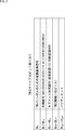
- FIG. 2 shows an example of TMCC carrier bit allocation.
- bit B 0 is a demodulation reference signal for the TMCC symbol
- bits B 1 to B 16 are synchronization signals
- bits B 17 to B 19 are.
- parity bits are assigned to bits B 122 to B 203 .
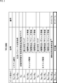
- FIG. 3 shows details of bits B 20 to B 121 of the TMCC information shown in FIG.
- bits B 20 to B 121 of the TMCC information bits B 20 to B 21 are system identifications, bits B 22 to B 25 are transmission parameter switching indexes, bit B 26 is a start control signal, and bits B 27 to B 21.
- Current information is assigned to 66 , next information is assigned to bits B 67 to B 106 , concatenated transmission phase correction amount is assigned to bits B 107 to B 109 , and bits B 110 to B 121 are undefined.
- TMCC signal has the above configuration.
- TMCC signal Example of TMCC signal to which this technology is applied
- new system introduction control information and time division control information are added to undefined bits (reserved bits) of TMCC information included in a TMCC signal.
- Fig. 4 shows an example of new system introduction control information.
- the new system introduction control information is assigned to 1 bit of bit B 110 among the undefined bits of TMCC information.
- bit B 110 of TMCC information when “0” is designated as bit B 110 of TMCC information, it indicates that a new method compatible with the existing method is introduced. On the other hand, when “1” is designated as the bit B 110 of the TMCC information, it means that the new system compatible with the existing system has not been introduced.
- FIG. 5 shows an example of time division control information.
- time division control information is assigned to 4 bits B 111 to B 114 .
- This time division control information includes information for each transmission frame unit such as an OFDM frame (time division information divided in a fixed transmission frame unit (time unit)).
- the time division control information can include information about an index (switching index) when switching from the existing system to the new system.
- the switching index for example, as shown in FIG. 5, it is possible to include information on the number of transmission frames until switching from the existing system to the new system.
- new system introduction control information and time division control information are added to undefined bits (reserved bits) of TMCC information included in the TMCC signal.
- the receiving apparatus 20 has the new system introduction control information. Based on the above, it is possible to determine whether or not the new method has been introduced into the existing method. In addition, the receiving device 20 can perform processing according to the time division control information when it is determined that the new method has been introduced into the existing method.
- the number of transmission frames until switching from the existing method to the new method is expressed from 15 frames before using the 4-bit value of bits B 111 to B 114 , but this number of frames is an example. However, the number of frames may be larger or smaller than 15 frames depending on the environment and the capability of the device. Then, here, the number of bits to be allocated is determined according to the number of frames to be expressed. For example, in addition to 4 bits, 3 or less bits or 5 or more bits may be assigned by using undefined bits of TMCC information.
- the receiving apparatus 20 switches from the existing scheme to the new scheme even with only the time division control information. Since the new method introduction control information can be specified, it is not always necessary to add the new method introduction control information.
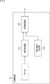
- FIG. 6 shows an example of the configuration of the transmission device 10 of FIG.
- the transmission device 10 is configured to include a signal processing unit 111, a TMCC signal generation unit 112, and an OFDM modulation unit 113.
- the signal processing unit 111 performs signal processing on the data of the broadcast content input as transmission data, and supplies the resulting data signal to the OFDM modulation unit 113.
- This signal processing includes, for example, forward error correction coding and modulation processing, and modulation processing such as time interleaving and frequency interleaving.
- the TMCC signal generator 112 generates a TMCC signal as a transmission control signal and supplies it to the OFDM modulator 113.
- the TMCC information included in this TMCC signal can include, for example, the TMCC information shown in FIG. 3 and time division control information using undefined bits.
- the OFDM modulation section 113 is (a part of) a transmission section that performs processing related to an OFDM frame as a transmission frame.
- the OFDM modulation unit 113 performs OFDM modulation processing on the data signal supplied from the signal processing unit 111 and the TMCC signal supplied from the TMCC signal generation unit 112, and the resulting modulated signal is transmitted by the transmission antenna It is transmitted (transmitted) as a broadcast signal via the drawing.
- OFDM modulation processing for example, an OFDM frame configuration, an inverse fast Fourier transform (IFFT) that transforms a frequency domain signal into a time domain signal, and a guard interval (GI: Guard Interval) are added. Including processing to do.
- IFFT inverse fast Fourier transform
- GI Guard Interval
- the transmitter 10 is configured as described above.
- the existing system and the new system are described without making a particular distinction, but the signal processing unit 111, the TMCC signal generation unit 112, and the OFDM modulation unit 113 are compatible with both systems. It corresponds.
- 2K content corresponding to 2K video is processed as broadcast content and the broadcast signal (2K broadcast signal) is transmitted
- 4K content corresponding to 4K video is transmitted as broadcast content.
- the broadcast signal (4K broadcast signal) is transmitted.
- the new system is introduced while maintaining compatibility with the existing system, so that the transmission device 10 transmits a 2K broadcast signal and a 4K broadcast signal.
- the transmission device 10 transmits a 2K broadcast signal and a 4K broadcast signal.
- the second phase since the broadcasting service of the existing system is stopped and only the operation of the new system is performed, only 4K broadcast signals are transmitted from the transmission device 10.
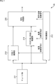
- FIG. 7 shows an example of the configuration of the receiving device 20 of FIG.
- the receiving device 20 includes a tuner unit 211, a TMCC demodulation unit 212, an ISDB-T demodulation unit 213, a next-generation terrestrial broadcasting demodulation unit 214, and a signal switching unit 215.
- the tuner section 211 is (a part of) a receiving section that selects a predetermined frequency band of a broadcast signal received via a receiving antenna (not shown).
- the tuner unit 211 supplies the broadcast signal in the selected frequency band to the TMCC demodulation unit 212, the ISDB-T demodulation unit 213, and the next-generation terrestrial broadcast demodulation unit 214.
- the OFDM demodulation process for example, a process of removing a guard interval (GI), a fast Fourier transform (FFT) that transforms a signal in the time domain into a signal in the frequency domain, or OFDM.
- GI guard interval
- FFT fast Fourier transform
- a process of demodulating the frame is performed.
- this OFDM demodulation processing may be performed by a demodulation circuit such as the ISDB-T demodulation unit 213 or the next-generation terrestrial broadcast demodulation unit 214.
- the TMCC demodulation unit 212 performs TMCC demodulation processing on the OFDM frame supplied from the tuner unit 211 and acquires a TMCC signal.
- the TMCC demodulation unit 212 supplies the TMCC information included in the acquired TMCC signal to at least one demodulation unit of the ISDB-T demodulation unit 213 and the next-generation terrestrial broadcast demodulation unit 214.
- the TMCC demodulation unit 212 supplies the power control signal #1 to the ISDB-T demodulation unit 213 based on the TMCC information included in the acquired TMCC signal and the information such as (the type of) the broadcast signal being received.
- the signal #2 is supplied to the next-generation terrestrial broadcasting demodulation unit 214, and the signal switching control signal is supplied to the signal switching unit 215.
- the power supply control signal #1 is a control signal for controlling the power supplied from the power supply unit (not shown) to the ISDB-T demodulation unit 213.
- the power supply control signal #1 is composed of an H level signal or an L level signal.
- the power source control signal #1 has an H level, power is supplied to the ISDB-T demodulation unit 213, and when it has an L level, an ISDB-T signal. The power supply to the demodulation unit 213 is stopped.
- the power supply control signal #2 is a control signal for controlling the power supplied from the power supply unit to the next-generation terrestrial broadcast demodulation unit 214.
- the power supply control signal #2 is composed of an H level signal or an L level signal.
- the power control signal #2 is at the H level, power is supplied to the next generation terrestrial broadcast demodulation unit 214, and when it is at the L level, the next generation ground signal is generated. The power supply to the broadcast demodulation unit 214 is stopped.
- the signal switching control signal is a control signal for switching the output of the signal switching unit 215 to the output signal from the ISDB-T demodulation unit 213 or the output signal from the next-generation terrestrial broadcast demodulation unit 214.
- the signal switching control signal is at the H level
- the output signal from the next-generation terrestrial broadcast demodulation unit 214 is output
- the output signal from the ISDB-T demodulation unit 213 is the output signal. Is output.
- the ISDB-T demodulation unit 213 is a demodulation circuit (for example, demodulation LSI) compatible with the ISDB-T system specifications as an existing system.
- demodulation LSI demodulation circuit
- the ISDB-T demodulation unit 213 is supplied with the OFDM frame from the tuner unit 211 and the TMCC information from the TMCC demodulation unit 212.
- the ISDB-T demodulation unit 213 performs demodulation processing on the data signal obtained from the OFDM frame based on the TMCC information, and supplies the output signal obtained as a result to the signal switching unit 215.
- the power supplied from the power supply unit is controlled based on the power supply control signal #1 supplied from the TMCC demodulation unit 212.
- the next-generation terrestrial broadcast demodulation unit 214 is a demodulation circuit (for example, demodulation LSI) compatible with the specifications of the next-generation terrestrial broadcast system as a new system.
- demodulation LSI demodulation circuit
- the next-generation terrestrial broadcast demodulation unit 214 is supplied with the OFDM frame from the tuner unit 211 and the TMCC information from the TMCC demodulation unit 212.
- the next-generation terrestrial broadcast demodulation unit 214 performs demodulation processing on the data signal obtained from the OFDM frame based on the TMCC information, and supplies the output signal obtained as a result to the signal switching unit 215.
- the power supplied from the power supply unit is controlled based on the power supply control signal #2 supplied from the TMCC demodulation unit 212.
- the demodulation processing performed by the ISDB-T demodulation unit 213 and the next-generation terrestrial broadcasting demodulation unit 214 includes, for example, frequency deinterleave, time deinterleave, forward error correction demodulation/decoding processing, and the like.
- the signal switching unit 215 outputs the output signal input from the ISDB-T demodulation unit 213 and the output signal input from the next-generation terrestrial broadcasting demodulation unit 214 based on the signal switching control signal supplied from the TMCC demodulation unit 212.
- One of the output signals is switched to be output to a subsequent unit (for example, a decoder or the like).
- the receiving device 20 is configured as described above.
- the receiving device 20 shown in FIG. 7 has an ISDB-T demodulation unit 213 and a next-generation terrestrial broadcasting demodulation unit 214 as demodulation circuits, so it can be said that it is a dual-type receiving device 20D.
- the existing system receiver 20L has only the ISDB-T demodulation unit 213 as a demodulation circuit
- the new system receiver 20N has only the next-generation terrestrial broadcast demodulation unit 214 as the demodulation circuit. become.
- the new system is introduced while maintaining compatibility with the existing system, so that the transmitter 10 will transmit the 2K broadcast signal and the 4K broadcast signal.
- the receiving device 20L receives the 2K broadcast signal and displays 2K video corresponding to the 2K content
- the new system receiving device 20N receives the 4K broadcast signal and displays 4K video corresponding to the 4K content.
- the broadcasting service of the existing system since the broadcasting service of the existing system is stopped and only the operation of the new system is performed, only the 4K broadcast signal is transmitted from the transmitting device 10, and the reception of the new system is performed.
- the device 20N receives the 4K broadcast signal and displays the 4K video corresponding to the 4K content.
- the existing system receiver 20L does not support 4K broadcast signals.
- the dual receiver 20D shown in FIG. 7 will be described as an example of the receiver 20.
- a of FIG. 8 shows a timing chart of the time division control information included in the TMCC information, that is, the 4-bit value of bits B 111 to B 114 .
- 8B and 8C are timing charts of the power supply control signal #1 and the power supply control signal #2, respectively.
- D of FIG. 8 shows a timing chart of the signal switching control signal. In FIG. 8, the direction of time is from left to right.
- the 4-bit value of bits B 111 to B 114 is “1111”, that is, a normal value. Further, the power supply control signal #1 becomes H level, the power supply control signal #2 becomes L level, and the signal switching control signal becomes L level.
- the dual receiver 20D receives the broadcast signal (2K broadcast signal) of the ISDB-T system, which is the existing system, and demodulates it by the ISDB-T demodulation unit 213 to support the ISDB-T system.
- the output signal (2K signal) is output via the signal switching unit 215.
- the dual receiver 20D displays 2K video corresponding to the 2K content.
- the power supply control signal #2 changes from L level to H level.
- the power supply to the next-generation terrestrial broadcast demodulation unit 214 is started, the next-generation terrestrial broadcast demodulation unit 214 starts operating, and broadcasting of the new-generation terrestrial broadcast system is performed. It becomes possible to perform demodulation processing on the signal (4K broadcast signal).
- the 4-bit values of bits B 111 to B 114 are '1101', '1100', '1011', '1010', '1001', '1000', '0111', '0110', '0101.
- the number of frames before switching is 13, 12, 11, 10, 9, 8, 7, 7, 6, 5 accordingly. , 4, 3, 2 in that order.
- 4-bit value of the bit B 111 ⁇ B 114 is, when it becomes '0000', the number of frames before switching to the next generation terrestrial broadcasting system from ISDB-T system is 1.
- the 4-bit value of bits B 111 to B 114 changes from '0000' to '1111', indicating that the ISDB-T system has been switched to the next-generation terrestrial broadcasting system. ..
- the signal switching control signal changes from the L level to the H level
- the power supply control signal #1 changes from the H level to the L level.
- the output of the signal switching unit 215 is switched from the output signal from the ISDB-T demodulation unit 213 to the output signal from the next-generation terrestrial broadcast demodulation unit 214, and at the same time, the ISDB-T demodulation unit 213.
- the supply of power to the ISDB-T demodulation unit 213 is stopped.
- 4-bit value of the bit B 111 ⁇ B 114 is '1111', that is, the normal value. Further, the power supply control signal #1 becomes L level, the power supply control signal #2 becomes H level, and the signal switching control signal becomes H level.
- the broadcast signal (4K broadcast signal) of the new next-generation terrestrial broadcasting system is received, and demodulation processing is performed by the next-generation terrestrial broadcasting demodulation unit 214 to generate the next-generation terrestrial broadcasting.
- An output signal (4K signal) corresponding to the method is output via the signal switching unit 215.
- the dual receiver 20D displays a 4K image corresponding to the 4K content.
- the operation shown in the timing chart of FIG. 8 is performed in the bidirectional receiving device 20D, and the following effects can be obtained, for example.
- the signal switching unit 215 can switch between the ISDB-T demodulation unit 213 and the next-generation terrestrial broadcasting demodulation unit 214 with the accuracy of the transmission frame unit based on the signal switching control signal.
- the dual receiver 20D has a demodulation circuit corresponding to the specifications of the existing system (demodulation system) and the specifications of the new system (demodulation system). It is possible to switch at high speed to a demodulation circuit corresponding to the (method).
- the power supply to the ISDB-T demodulation unit 213 is controlled based on the power supply control signal #1, and the power supply to the next-generation terrestrial broadcast demodulation unit 214 is controlled based on the power supply control signal #2. It is possible to minimize the period during which the T demodulation unit 213 and the next-generation terrestrial broadcast demodulation unit 214 operate simultaneously. As a result, the dual receiver 20D can reduce the overall power consumption when, for example, a new system is introduced.
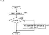
- step S201 the TMCC demodulation unit 212 acquires TMCC information (including new system introduction control information) from the OFDM demodulation result from the tuner unit 211. Then, the subsequent processing is executed according to the new system introduction control information included in the TMCC information.
- TMCC information including new system introduction control information
- step S202 the value of bit B 110 is determined.
- the process proceeds to step S203.
- step S203 the TMCC demodulation unit 212 to the signal switching unit 215 execute processing of time division control information.
- this time division control information for example, the operation shown in the timing chart of FIG. 8 described above is performed based on the time division control information (the value of 4 bits of bits B 111 to B 114 ).
- step S203 If it is determined in the determination processing of step S202 that the value of the bit B 110 is “1”, that is, that the new method has not been introduced, the processing of step S203 is skipped.
- the dual receiver 20D can determine whether or not the new method has been introduced into the existing method based on the new method introduction control information (bit B 110 ) and execute the process according to the determination result. it can.
- the existing method is the ISDB-T method and the new method is the next-generation terrestrial broadcasting method.
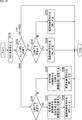
- step S231 the TMCC demodulation unit 212 acquires TMCC information (including time division control information) from the OFDM demodulation result from the tuner unit 211. Then, in accordance with the division control information when included in the TMCC information (4-bit value of the bit B 111 ⁇ B 114), the processing of steps S232 to 240 is executed.
- TMCC information including time division control information
- 4-bit value of the bit B 111-B 114 is '0000', '1110', or '1111' or '1101' which of ⁇ '0001' is determined.
- step S232 If it is determined in the determination processing of step S232 that the 4-bit value of bits B 111 to B 114 is '1110', that is, 15 frames before the switching, the processing proceeds to step S233. In the determination processing of step S233, it is determined whether or not the ISDB-T system broadcast signal is being received.
- step S233 If it is determined in the determination processing in step S233 that the ISDB-T system broadcast signal is being received (“YES” in step S233), the processing proceeds to step S234. Then, the TMCC demodulation unit 212 turns on the power supply control signal #2 for the next-generation terrestrial broadcasting demodulation unit 214, that is, supplies an H level signal (S234).
- the The generation terrestrial broadcast demodulation unit 214 is activated.
- step S233 determines whether the ISDB-T system broadcast signal is being received (“NO” in S233). If it is determined in the determination processing in step S233 that the ISDB-T system broadcast signal is not being received (“NO” in S233), the processing proceeds to step S235. Then, the TMCC demodulation unit 212 turns on the power supply control signal #2 for the ISDB-T demodulation unit 213, that is, supplies an H level signal (S235).
- the next-generation terrestrial broadcast demodulation unit 214 and The ISDB-T demodulation unit 213 is activated.
- step S234 or S235 ends, the processing is stopped until the next TMCC information is acquired. Then, when the next TMCC information is acquired, the processing shown in FIG. 10 is executed again.
- step S232 it is determined that the 4-bit value of bits B 111 to B 114 is any of '1101' to '0001', that is, between 14 frames before switching and 2 frames before. If it is determined, the process is stopped until the next TMCC information is acquired.
- step S232 when it is determined that the 4-bit value of the bits B 111 to B 114 is “0000”, that is, it is one frame before the switching, the processing proceeds to step S236. .. In the determination processing of step S236, it is determined whether or not the ISDB-T system broadcast signal is being received.
- step S236 When it is determined in the determination processing of step S236 that the ISDB-T system broadcast signal is being received (“YES” of S236), the processing proceeds to step S237, and the processing of steps S237 and S238 is executed. It is determined in the determination processing of step S236 that the ISDB-T system broadcast signal is being received (“YES” of S236), the processing proceeds to step S237, and the processing of steps S237 and S238 is executed. It
- the TMCC demodulation unit 212 supplies a signal for switching its input to the next-generation terrestrial broadcasting demodulation unit 214 as a signal switching control signal for the signal switching unit 215 (S237). Further, the TMCC demodulation unit 212 turns off the power supply control signal #1 for the ISDB-T demodulation unit 213, that is, supplies an L level signal (S238).
- the ISDB-T demodulation unit 213 is stopped by switching to the output signal from the next generation terrestrial broadcast demodulation unit 214.
- step S236 determines whether the ISDB-T system broadcast signal is being received (“NO” in S236). If it is determined in the determination processing in step S236 that the ISDB-T system broadcast signal is not being received (“NO” in S236), the processing proceeds to step S239, and the processing in steps S239 and S240. Is executed.
- the TMCC demodulation unit 212 supplies a signal for switching its input to the ISDB-T demodulation unit 213 as a signal switching control signal for the signal switching unit 215 (S239). Further, the TMCC demodulation unit 212 turns off the power supply control signal #1 for the next-generation terrestrial broadcasting demodulation unit 214, that is, supplies an L level signal (S240).
- step S238 or S240 ends, the processing is stopped until the next TMCC information is acquired. Then, when the next TMCC information is acquired, the processing shown in FIG. 10 is executed again.
- step S232 when it is determined that the 4-bit value of bits B 111 to B 114 is “1111”, that is, the normal value, the next TMCC information is acquired. Processing is stopped until Then, when the next TMCC information is acquired, the processing shown in FIG. 10 is executed again.
- the ISDB-T system has been described as a broadcasting system for terrestrial digital television broadcasting, but the present technology may be applied to other broadcasting systems.
- terrestrial broadcasting for example, satellite broadcasting using a broadcasting satellite (BS: Broadcasting Satellite) or communication satellite (CS: Communications Satellite), or cable broadcasting using a cable (CATV: Common) Antenna TeleVision) may be applied to broadcasting systems such as.
- BS Broadcasting Satellite
- CS Communications Satellite
- CATV Common
- Antenna TeleVision Antenna TeleVision
- the receiving device 20 (FIG. 1) has been described as being configured as a fixed receiver such as a television receiver or a set top box (STB), but the fixed receiver may be, for example, a recorder.
- Electronic devices such as game machines, personal computers, and network storage may be included.
- the receiving device 20 (FIG. 1) is not limited to a fixed receiver, and may be, for example, a mobile receiver such as a smartphone, a mobile phone, a tablet computer, an in-vehicle device mounted in a vehicle such as an in-vehicle TV, or a head mounted display.
- An electronic device such as a wearable computer such as (HMD: Head Mounted Display) may be included.
- the transmitter 10 having the configuration shown in FIG. 6 may be regarded as a modulator or a modulator (for example, a modulator circuit).
- the receiving device 20 having the configuration shown in FIG. 7 may be regarded as a demodulating device or a demodulating unit (for example, a demodulating circuit or a demodulating IC).
- a receiving device 20 having a communication function by connecting various servers to a communication line such as the Internet is provided.
- Various data such as contents and applications may be received by accessing various servers via a communication line such as the Internet and performing bidirectional communication.
- “2K video” is a video corresponding to a screen resolution of approximately 1920 ⁇ 1080 pixels
- “4K video” is a video corresponding to a screen resolution of approximately 3840 ⁇ 2160 pixels. is there.
- broadcast content 2K content of 2K video transmitted by the existing broadcast method (existing method) and 4K content of 4K video transmitted by the new broadcast method (new method) have been described.
- the broadcast content transmitted by the new method may be higher-quality content such as 8K video.
- “8K video” is a video that corresponds to a screen resolution of approximately 7680 ⁇ 4320 pixels.
- FIG. 11 is a diagram showing a configuration example of hardware of a computer that executes the series of processes described above by a program.
- a CPU Central Processing Unit
- ROM Read Only Memory
- RAM Random Access Memory
- An input/output interface 1005 is further connected to the bus 1004.
- An input unit 1006, an output unit 1007, a recording unit 1008, a communication unit 1009, and a drive 1010 are connected to the input/output interface 1005.
- the input unit 1006 includes a keyboard, a mouse, a microphone and the like.
- the output unit 1007 includes a display, a speaker and the like.
- the recording unit 1008 includes a hard disk, a non-volatile memory, or the like.
- the communication unit 1009 includes a network interface or the like.
- the drive 1010 drives a removable recording medium 1011 such as a magnetic disk, an optical disk, a magneto-optical disk, or a semiconductor memory.
- the CPU 1001 loads the program recorded in the ROM 1002 or the recording unit 1008 into the RAM 1003 via the input/output interface 1005 and the bus 1004, and executes the program. A series of processing is performed.
- the program executed by the computer 1000 can be provided by being recorded in, for example, a removable recording medium 1011 as a package medium or the like. Further, the program can be provided via a wired or wireless transmission medium such as a local area network, the Internet, or digital satellite broadcasting.
- the program can be installed in the recording unit 1008 via the input/output interface 1005 by mounting the removable recording medium 1011 in the drive 1010. Further, the program can be received by the communication unit 1009 via a wired or wireless transmission medium and installed in the recording unit 1008. In addition, the program can be installed in advance in the ROM 1002 or the recording unit 1008.
- the processing performed by the computer according to the program does not necessarily have to be performed in time series in the order described as the flowchart. That is, the processing performed by the computer according to the program also includes processing that is executed in parallel or individually (for example, parallel processing or object processing). Further, the program may be processed by one computer (processor) or may be processed in a distributed manner by a plurality of computers.
- the present technology can have the following configurations.
- a receiver for receiving a transmission frame transmitted from the transmitter A demodulation unit that performs a demodulation process on a data signal obtained from the transmission frame based on a transmission control signal obtained from the received transmission frame,
- the transmission control signal includes time-division control information regarding time-division control, as control information according to the introduction of the second method that is compatible with the first method.
- the demodulation unit operates according to the time division control information.
- the receiving apparatus wherein the index includes information about the number of the transmission frames until the switching from the first method to the second method.
- the demodulation unit A first demodulation unit compatible with the first system; And a second demodulation unit compatible with the second system, The receiving device according to (1), wherein the first demodulation unit and the second demodulation unit are switched according to the time division control information.
- the receiving device (5), wherein the power supply to the first demodulation unit and the power supply to the second demodulation unit are controlled according to the time division control information.
- a signal switching unit that switches between a first output signal output from the first demodulation unit and a second output signal output from the second demodulation unit;
- the signal switching unit operates according to the time division control information.
- the receiving device according to (5) or (6).
- the time division control information is information for each transmission frame unit, and includes information regarding the number of the transmission frames until switching from the first method to the second method, When switching from the first method to the second method, The first demodulation unit and the second demodulation unit operate simultaneously until the number of the transmission frames indicates switching of the systems, When the number of the transmission frames indicates the switching of the systems, the signal switching unit switches the output from the first output signal to the second output signal, and the first demodulation unit performs the operation.
- the receiving device according to (7) above.
- the first method includes an ISDB-T method
- the second method includes a next-generation method of the ISDB-T method
- the transmission frame includes an OFDM frame
- the reception device according to any one of (1) to (8), wherein the transmission control signal includes a TMCC signal.
- a receiver for receiving a transmission frame transmitted from the transmitter A receiving unit including a demodulation unit that performs a demodulation process on a data signal obtained from the transmission frame based on a transmission control signal obtained from the received transmission frame,
- the time division control information included in the transmission control signal is based on the time division control information regarding time division control as control information according to the introduction of the second method compatible with the first method.
- a generation unit that generates a transmission control signal including time division control information regarding time division control as control information according to the introduction of the second method that is compatible with the first method, A transmitter that transmits a transmission frame including the generated transmission control signal.
- the time-division control information includes information about an index when switching from the first method to the second method.
- the transmitter according to (13), wherein the index includes information about the number of the transmission frames until the switching from the first method to the second method.
- the first method includes an ISDB-T method
- the second method includes a next-generation method of the ISDB-T method
- the transmission frame includes an OFDM frame
- the transmission device according to any one of (11) to (14), wherein the transmission control signal includes a TMCC signal.
- the transmitter is As a control information according to the introduction of the second method that is compatible with the first method, a transmission control signal including time division control information regarding time division control is generated, A transmission method for transmitting a transmission frame including the generated transmission control signal.
Landscapes
- Engineering & Computer Science (AREA)
- Signal Processing (AREA)
- Computer Networks & Wireless Communication (AREA)
- Multimedia (AREA)
- Two-Way Televisions, Distribution Of Moving Picture Or The Like (AREA)
- Circuits Of Receivers In General (AREA)
Abstract
La technologie concerne un dispositif de réception, un procédé de réception, un dispositif de transmission et un procédé de transmission qui permettent une implantation plus adéquate de nouvelles normes de diffusion. L'invention concerne un dispositif de réception comprenant : une unité de réception permettant de recevoir des trames de transmission transmises à partir d'un dispositif de transmission ; et une unité de démodulation permettant d'effectuer un processus de démodulation sur un signal de données, obtenu à partir des trames de transmission reçues, en fonction d'un signal de commande de transmission obtenu à partir des trames de transmission, où : le signal de commande de transmission contient des informations de commande par répartition dans le temps, concernant la commande de la répartition dans le temps, en tant qu'informations de commande correspondant à l'implantation d'une deuxième norme compatible avec une première norme ; et l'unité de démodulation fonctionne selon les informations de commande de répartition dans le temps. Cette technologie est applicable, par exemple, à des systèmes de transmission qui prennent en charge des normes de diffusion telles que la norme ISDB-T.
Priority Applications (1)
| Application Number | Priority Date | Filing Date | Title |
|---|---|---|---|
| US17/296,493 US11431536B2 (en) | 2018-12-12 | 2019-11-29 | Receiving device, receiving method, transmitting device, and transmitting method |
Applications Claiming Priority (2)
| Application Number | Priority Date | Filing Date | Title |
|---|---|---|---|
| JP2018-232142 | 2018-12-12 | ||
| JP2018232142A JP7392260B2 (ja) | 2018-12-12 | 2018-12-12 | 受信装置、及び受信方法 |
Publications (1)
| Publication Number | Publication Date |
|---|---|
| WO2020121843A1 true WO2020121843A1 (fr) | 2020-06-18 |
Family
ID=71075367
Family Applications (1)
| Application Number | Title | Priority Date | Filing Date |
|---|---|---|---|
| PCT/JP2019/046728 Ceased WO2020121843A1 (fr) | 2018-12-12 | 2019-11-29 | Dispositif de réception, procédé de réception, dispositif de transmission, et procédé de transmission |
Country Status (4)
| Country | Link |
|---|---|
| US (1) | US11431536B2 (fr) |
| JP (1) | JP7392260B2 (fr) |
| TW (1) | TWI730520B (fr) |
| WO (1) | WO2020121843A1 (fr) |
Cited By (1)
| Publication number | Priority date | Publication date | Assignee | Title |
|---|---|---|---|---|
| JP2022146130A (ja) * | 2021-03-22 | 2022-10-05 | 日本放送協会 | 送信サーバ、送信装置、受信装置及びプログラム |
Citations (1)
| Publication number | Priority date | Publication date | Assignee | Title |
|---|---|---|---|---|
| JP2018101862A (ja) * | 2016-12-19 | 2018-06-28 | パナソニック インテレクチュアル プロパティ コーポレーション オブ アメリカPanasonic Intellectual Property Corporation of America | 送信装置、送信方法、受信装置、及び受信方法 |
Family Cites Families (8)
| Publication number | Priority date | Publication date | Assignee | Title |
|---|---|---|---|---|
| JP2011097421A (ja) * | 2009-10-30 | 2011-05-12 | Panasonic Corp | 通信端末装置及びコンテンツデータ受信方法 |
| JP5553146B2 (ja) | 2010-02-17 | 2014-07-16 | ソニー株式会社 | 受信装置、情報処理方法、およびプログラム |
| JP5284500B2 (ja) * | 2011-03-16 | 2013-09-11 | 株式会社東芝 | 連結送信システム及び連結送信方法 |
| US8670505B2 (en) | 2011-03-31 | 2014-03-11 | Subrahmanya Kondageri Shankaraiah | Early detection of segment type using BPSK and DBPSK modulated carriers in ISDB-T receivers |
| JP6118616B2 (ja) * | 2013-03-29 | 2017-04-19 | 富士通株式会社 | 受信機および同期補正方法 |
| WO2018008428A1 (fr) * | 2016-07-08 | 2018-01-11 | ソニーセミコンダクタソリューションズ株式会社 | Appareil de réception, appareil de transmission et procédé de traitement de données |
| JP6953693B2 (ja) | 2016-09-15 | 2021-10-27 | ソニーグループ株式会社 | 送信装置、及び、送信方法 |
| JP7201351B2 (ja) | 2018-07-13 | 2023-01-10 | マクセル株式会社 | デジタル放送変調波の伝送方法 |
-
2018
- 2018-12-12 JP JP2018232142A patent/JP7392260B2/ja active Active
-
2019
- 2019-11-29 US US17/296,493 patent/US11431536B2/en active Active
- 2019-11-29 WO PCT/JP2019/046728 patent/WO2020121843A1/fr not_active Ceased
- 2019-12-02 TW TW108143899A patent/TWI730520B/zh not_active IP Right Cessation
Patent Citations (1)
| Publication number | Priority date | Publication date | Assignee | Title |
|---|---|---|---|---|
| JP2018101862A (ja) * | 2016-12-19 | 2018-06-28 | パナソニック インテレクチュアル プロパティ コーポレーション オブ アメリカPanasonic Intellectual Property Corporation of America | 送信装置、送信方法、受信装置、及び受信方法 |
Non-Patent Citations (1)
| Title |
|---|
| "Digital Video Broadcasting (DVB); Frame structure channel coding and modulation for a second generation digital terrestrial television broadcasting system (DVB-T2);Draft ETSI EN 302 755", ETSI DRAFT; DRAFT ETSI EN 302 755,, no. V1.4.1, July 2015 (2015-07-01), pages 1 - 23, XP014225121 * |
Cited By (2)
| Publication number | Priority date | Publication date | Assignee | Title |
|---|---|---|---|---|
| JP2022146130A (ja) * | 2021-03-22 | 2022-10-05 | 日本放送協会 | 送信サーバ、送信装置、受信装置及びプログラム |
| JP7587450B2 (ja) | 2021-03-22 | 2024-11-20 | 日本放送協会 | 送信サーバ、送信装置及びプログラム |
Also Published As
| Publication number | Publication date |
|---|---|
| JP7392260B2 (ja) | 2023-12-06 |
| US20220052888A1 (en) | 2022-02-17 |
| JP2020096266A (ja) | 2020-06-18 |
| US11431536B2 (en) | 2022-08-30 |
| TW202029712A (zh) | 2020-08-01 |
| TWI730520B (zh) | 2021-06-11 |
Similar Documents
| Publication | Publication Date | Title |
|---|---|---|
| TWI741420B (zh) | 送訊裝置、送訊方法、收訊裝置及收訊方法 | |
| JP7529086B2 (ja) | 送信装置、送信方法、受信装置、及び受信方法 | |
| JP7400299B2 (ja) | 送信装置、送信方法、受信装置、及び受信方法 | |
| JP7423949B2 (ja) | 送信装置、送信方法、受信装置、及び、受信方法 | |
| WO2018051818A1 (fr) | Dispositif de transmission, procédé de transmission, dispositif de réception et procédé de réception | |
| JP7214910B2 (ja) | 受信装置、及び、受信方法 | |
| WO2012117917A1 (fr) | Dispositif de transmission, procédé de traitement d'informations, programme et système de transmission | |
| JP2010538562A (ja) | 放送システム内でサービス受信を保証する方法及びシステム | |
| WO2020121843A1 (fr) | Dispositif de réception, procédé de réception, dispositif de transmission, et procédé de transmission | |
| US20250253974A1 (en) | Transmission device, transmission method, reception device, and reception method | |
| WO2025105154A1 (fr) | Dispositif de transmission, procédé de transmission, dispositif de réception et procédé de réception | |
| WO2026063218A1 (fr) | Dispositif d'émission, procédé d'émission, dispositif de réception et procédé de réception | |
| WO2025229877A1 (fr) | Dispositif d'émission, procédé d'émission, dispositif de réception et procédé de réception | |
| WO2025057715A1 (fr) | Dispositif de transmission, procédé de transmission, dispositif de réception et procédé de réception |
Legal Events
| Date | Code | Title | Description |
|---|---|---|---|
| 121 | Ep: the epo has been informed by wipo that ep was designated in this application |
Ref document number: 19897202 Country of ref document: EP Kind code of ref document: A1 |
|
| NENP | Non-entry into the national phase |
Ref country code: DE |
|
| 122 | Ep: pct application non-entry in european phase |
Ref document number: 19897202 Country of ref document: EP Kind code of ref document: A1 |