WO2020121853A1 - 空気入りタイヤ - Google Patents
空気入りタイヤ Download PDFInfo
- Publication number
- WO2020121853A1 WO2020121853A1 PCT/JP2019/046888 JP2019046888W WO2020121853A1 WO 2020121853 A1 WO2020121853 A1 WO 2020121853A1 JP 2019046888 W JP2019046888 W JP 2019046888W WO 2020121853 A1 WO2020121853 A1 WO 2020121853A1
- Authority
- WO
- WIPO (PCT)
- Prior art keywords
- protrusion
- protrusions
- pneumatic tire
- tire
- region
- Prior art date
- Legal status (The legal status is an assumption and is not a legal conclusion. Google has not performed a legal analysis and makes no representation as to the accuracy of the status listed.)
- Ceased
Links
Images







Classifications
-
- B—PERFORMING OPERATIONS; TRANSPORTING
- B60—VEHICLES IN GENERAL
- B60C—VEHICLE TYRES; TYRE INFLATION; TYRE CHANGING; CONNECTING VALVES TO INFLATABLE ELASTIC BODIES IN GENERAL; DEVICES OR ARRANGEMENTS RELATED TO TYRES
- B60C13/00—Tyre sidewalls; Protecting, decorating, marking, or the like, thereof
Definitions
- the present invention relates to a pneumatic tire.
- Patent Document 1 a technique for making unevenness present on the outer surface of the sidewall part inconspicuous is known.
- Patent Document 1 a technique for making unevenness present on the outer surface of the sidewall part inconspicuous is known.
- Patent Document 1 a technique for making unevenness present on the outer surface of the sidewall part inconspicuous.
- Patent Document 1 a technique for making unevenness present on the outer surface of the sidewall part inconspicuous.
- Patent Document 1 a technique for making unevenness present on the outer surface of the sidewall part inconspicuous.
- Patent Document 1 a technique for making unevenness present on the outer surface of the sidewall part inconspicuous.
- a plurality of circumferential direction pattern element rows in which a plurality of pattern elements having the same contour shape are continuously provided in the tire circumferential direction, and a plurality of pattern elements are in a tire radial direction.
- a plurality of rows of radial pattern elements arranged in series are formed.
- the present invention has been made in view of such a situation, and an object thereof is to provide a pneumatic tire in which the appearance of the sidewall portion is improved even when the gauge thickness of the sidewall portion is reduced.
- a pneumatic tire (pneumatic tire 1) includes a tread portion (tread portion 2) that is in contact with a road surface, and a sidewall portion (sidewall portion 3) that is continuous with the tread portion and that is located inside the tire radial direction of the tread portion. ) And, including.
- a micro region (micro region 10) having a plurality of protrusions (protrusions 20) is formed on the outer surface of the sidewall portion.
- a plurality of minute regions are formed along the tire circumferential direction or the tire radial direction. The area of the minute region is smaller than 0.3 cm 2 , and the height of the protrusion is 0.01 to 0.1 mm.
- the appearance of the sidewall portion is improved.
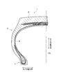
- FIG. 1 is a cross-sectional view of a pneumatic tire along a tire width direction and a tire radial direction.
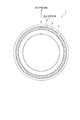
- FIG. 2 is a side view of the pneumatic tire.
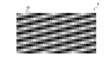
- FIG. 3 is a partially enlarged view of FIG.
- FIG. 4 is a sectional view as seen from the direction AA of FIG.
- FIG. 5 is a diagram illustrating an angle of the protrusion according to the embodiment of the present invention.
- FIG. 6 is a diagram for explaining the effect of the present invention.
- FIG. 7A is a diagram illustrating an array of minute regions according to another embodiment of the present invention.
- FIG. 7B is a diagram for explaining the effect of the present invention.
- FIG. 8A is a diagram illustrating an array of minute regions according to another embodiment of the present invention.
- FIG. 8A is a diagram illustrating an array of minute regions according to another embodiment of the present invention.
- FIG. 8B is a diagram for explaining the effect of the present invention.
- FIG. 9 is a diagram illustrating a mark according to another embodiment of the present invention.
- FIG. 10 is a sectional view as seen from the direction BB in FIG.
- FIG. 11 is a diagram illustrating a protrusion according to another embodiment of the present invention.
- FIG. 12 is a diagram illustrating a protrusion according to still another embodiment of the present invention.
- FIG. 13 is a partially enlarged view of FIG.
- FIG. 14 is a diagram illustrating an angle of the protrusion according to FIG.
- FIG. 15 is a diagram illustrating a protrusion according to still another embodiment of the present invention.
- FIG. 16 is a partially enlarged view of FIG.
- FIG. 17 is a diagram illustrating an angle of the protrusion according to FIG.
- FIG. 18 is a diagram illustrating a sparse and dense distribution in which the degree of denseness of a plurality of protrusions changes.
- FIG. 19 is a diagram showing a change in appearance when the decorative region according to the present embodiment is viewed at different angles.
- FIG. 1 is a partial cross-sectional view of a pneumatic tire 1 according to this embodiment. Specifically, FIG. 1 is a cross-sectional view of the pneumatic tire 1 taken along the tire width direction and the tire radial direction. Note that FIG. 1 shows only one side based on the tire equator line CL. FIG. 2 is a side view of the pneumatic tire 1 according to this embodiment.
- the pneumatic tire 1 includes a tread portion 2, a sidewall portion 3, a carcass 6, and a bead portion 7.
- the tread portion 2 is a portion that comes into contact with the road surface (not shown).
- the tread portion 2 is formed with a pattern (not shown) according to the usage environment of the pneumatic tire 1 and the type of vehicle to which the pneumatic tire 1 is mounted.
- Sidewall part 3 is connected to tread part 2 and is located inside tire radial direction of tread part 2.
- the sidewall portion 3 is an area from the tire width direction outer end of the tread portion 2 to the upper end of the bead portion 7.
- the carcass 6 forms the skeleton of the pneumatic tire 1.
- the carcass 6 has a radial structure having carcass cords (not shown) radially arranged along the tire radial direction.
- the carcass 6 is not limited to the radial structure, and may have a bias structure in which the carcass cords are arranged so as to intersect in the tire radial direction.
- the bead portion 7 is continuous with the sidewall portion 3 and is located inside the sidewall portion 3 in the tire radial direction.
- the bead portion 7 has an annular shape, and the carcass 6 is folded back from the tire width direction inner side to the tire width direction outer side via the bead portion 7.
- a decorative area 4 is formed on the outer surface of the sidewall portion 3.
- the decorative region 4 is formed in an annular shape along the tire circumferential direction. Although the details of the decoration area 4 will be described later, a large number of protrusions 20 or a mark is formed in the decoration area 4.
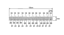
- FIG. 3 is an enlarged view of the area 5 shown in FIG.
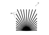
- the decoration area 4 is composed of a plurality of minute areas 10.
- the minute regions 10 are arranged along the tire circumferential direction and the tire radial direction. Further, the respective minute regions 10 are arranged adjacent to each other. As shown in FIG. 3, the length of the minute region 10 in the tire circumferential direction is 1 mm. Similarly, the length of the minute region 10 in the tire circumferential direction is also 1 mm. Therefore, the area of the minute region 10 is 1 mm 2 . However, the area of the minute region 10 is not limited to this. The area of the minute region 10 may be smaller than 0.3 cm 2 .
- a plurality of protrusions 20 are formed in each minute region 10.
- the minute region 10 in this embodiment is a region formed by the plurality of protrusions 20.
- the shape of the protrusion 20 is linear (blade-like) when the protrusion 20 is viewed from above.
- the shape of the projection 20 in a top view is described as a straight line, but the shape is not limited to this.
- the shape of the protrusion 20 in a top view may be a curved line.
- all the protrusions 20 are formed in a radial shape when viewed from above.
- the angle of the protrusion 20 in a top view changes periodically along the tire circumferential direction.
- the minute area 10 in this embodiment constitutes a predetermined unit.
- the predetermined unit is, for example, 12 mm square. That is, in the present embodiment, 144 minute regions 10 are aggregated to form a predetermined unit. Then, the predetermined units are repeatedly arranged along the tire circumferential direction and the tire longitudinal direction to form the decorative region 4.
- the height of the protrusion 20 is 0.03 mm.
- the height of the protrusion 20 is not limited to this.
- the height of the protrusion 20 may be in the range of 0.01 mm to 0.1 mm.
- the shape of the protrusion 20 in a side view is, for example, a trapezoid having an upper surface of 0.02 mm.
- the inclination angle from the upper surface to the lower surface is 45 degrees as an example.
- the shape of the protrusion 20 in a side view may be rectangular or dome-shaped.
- FIG. 5 shows the protrusion 20 in the center of the minute region 10.
- the protrusion 20 is defined as the central protrusion in the center of the minute region 10.
- the angle of the projection 20 in a top view changes so as to rotate periodically along the tire circumferential direction.
- the angles of the adjacent protrusions 20 in a top view are different.
- the angle of the protrusion 20 in a top view changes periodically by 30 degrees along the tire circumferential direction.
- the twelve minute regions 10 in the tire circumferential direction form one pattern row.
- the angle of the protrusion 20 in a top view may periodically change by 30 degrees along the tire radial direction. That is, the twelve minute regions 10 in the tire radial direction may form one pattern row.
- the minute region 10 having the plurality of protrusions 20 is formed on the outer surface of the sidewall portion 3.
- a plurality of minute regions 10 are formed along the tire circumferential direction or the tire radial direction.
- the area of the minute region 10 is smaller than 0.3 cm 2 , and the height of the protrusion 20 is 0.01 to 0.1 mm.
- the shape of the protrusion 20 is linear when the protrusion 20 is viewed from above.
- the angles of the central protrusions in the top view are different (see FIG. 5). Therefore, the angle of the central protrusion in top view changes so as to rotate periodically along the tire circumferential direction.
- the angle at which the light incident on the sidewall portion 3 is reflected changes depending on the angle of the line of sight when the user looks at the sidewall portion 3. Therefore, as shown in FIG. 6, the user feels different brightness for each minute region 10.
- the side wall part 3 (decoration region 4) appears to be moving.
- the light is moving according to the rotation of the pneumatic tire 1 or the change of the observation direction of the user.
- the appearance of the sidewall portion 3 is improved.
- the external appearance of the sidewall portion 3 is the visibility of the sidewall portion 3, the visibility, and the like.
- the arrangement method of the minute regions 10 is not limited to the example of FIG.
- the positions of the minute regions 10 arranged in the tire radial direction may be appropriately changed.
- the sidewall portion 3 (decoration region 4) having various reflection angles of light is realized.
- the mark 30 may be formed on the sidewall portion 3 (decoration region 4).
- the mark 30 will be described with reference to FIGS. 9 and 10.
- the mark 30 is, for example, a mark.
- a recess 50 having a predetermined depth is formed in the decorative region 4 along the tire width direction.
- a plurality of second protrusions 40 are formed in the recess 50.
- the mark 30 is formed by the plurality of second protrusions 40.
- the depth of the recess 50 is 0.4 mm as an example, but the depth is not limited to this.
- the height of the second protrusion 40 is 0.35 mm as an example, but the height is not limited to this.
- the height of the second protrusion 40 may be in the range of 0.1 to 1.0 mm.
- the black of the mark 30 formed by the plurality of second protrusions 40 is more prominent than the normal outer surface of the tire. Furthermore, the mark 30 becomes more prominent due to the comparison between the minute region 10 that seems to be moving and the mark 30 that does not move.
- the minute regions 10 are formed radially, but the present invention is not limited to this.
- the minute regions 10 may be formed in parallel.
- the angle in top view that periodically changes along the tire circumferential direction may be 90 degrees as shown in FIG. 11. Even in this case, the same effects as those described above can be obtained.
- the total extension length of the protrusions 20 per area of the minute region 10 may be 2 mm to 15 mm. Since the area of the minute region 10 is 1 mm 2 as an example, the total extension length of the protrusions 20 in 1 mm 2 may be 2 mm to 15 mm. If the total extension length of the protrusions 20 is less than the above value, it may be difficult for the user to perceive a glossy feeling. On the other hand, when the total extension length of the protrusions 20 is greater than the above value, the shadow of the protrusions 20 may make the microscopic region 10 appear dark and the glossiness may be reduced. In other words, if the total extension length of the protrusions 20 is the above value, a glossy appearance can be obtained.
- the total extension length of the protrusions 20 may be 7 mm to 10 mm. This gives a more glossy appearance.
- the extension length of the protruding portion 20 means the length of the protruding portion 20 along the tire circumferential direction, the length of the protruding portion 20 along the tire radial direction, and the tire circumferential direction of the protruding portion 20 or the tire radial direction. Includes the length along the diagonal direction with respect to.
- the ratio X/Y may be 0.3 or less.
- the ratio X/Y is larger than 0.3, the black contrast of the mark 30 is reduced, and the visibility of the mark 30 may be reduced. In other words, if the ratio X/Y is 0.3 or less, the visibility of the mark 30 is improved.
- protrusions having different shapes may be formed in the minute region 10.
- protrusions 20 and protrusions 21 having different shapes may be formed in the minute region 10.
- the protrusion 20 is linear as in FIG.
- the protruding portion 21 has a curved shape (wave shape).
- the linear protrusions 20 and the curved protrusions 21 are alternately formed along the tire circumferential direction or the tire radial direction. This effectively diffuses the reflected light and improves the visibility.
- the angles of the protrusions 20 and 21 in the top view change so as to rotate periodically along the tire circumferential direction. As a result, the same effect as the example shown in FIG. 5 can be obtained.
- the heights of the protrusions 20 and 21 shown in FIG. 12 are the same as those in FIG.
- the angle of the curved protrusion 21 in a top view may be defined as the angle of a straight line connecting the end points of the protrusion 21. Further, the angle of the curved protrusion 21 in a top view may be defined as the angle of a straight line connecting the center points of vibrations applied to the curve. Further, the angle of the curved protrusion 21 in a top view may be defined as the angle of a straight line that approximates the curve by an approximation method (for example, the least squares method).
- the center of the radially formed protrusions 20 is not particularly limited, but the center of the radially formed protrusions 20 is, as shown in FIGS. May exist within.
- the protrusion 20 may be formed so as to radiate from the center existing in the minute region 10 as shown in FIGS. 15 and 16. This effectively diffuses the reflected light and improves visibility.
- the above-mentioned predetermined unit is 24 mm square. That is, in FIG. 15, 576 minute regions 10 are aggregated to form a predetermined unit.
- the angle of the projection 20 in a top view changes so as to rotate periodically along the tire circumferential direction.
- FIG. 17 shows the rotation of the angle of the minute area 10 for 12 mm, but the remaining minute area 10 for 12 mm also rotates periodically in the same manner.
- the height of the protrusion 20 shown in FIG. 15 is the same as that in FIG.
- a sparse/dense distribution in which the degree of denseness of the plurality of protrusions 20 changes may be formed in the minute region 10 in which the plurality of protrusions 20 are radially formed. Since the plurality of protrusions 20 are radially formed, the protrusions 20 are densely arranged near the center of the radiation. As a result, a dense region 60 in which the protrusions 20 are densely formed is formed near the center of radiation. On the other hand, in the minute area 10, the distance between the protrusions 20 becomes wider as the distance from the dense area 60 increases. Thereby, the sparse region 70 in which the interval between the protrusions 20 is wide is formed.
- the dense area 60 and the sparse area 70 have different amounts of light reflection (brightness) by the protrusions 20. Therefore, by forming the sparse and dense distribution in which the degree of denseness of the protrusions 20 changes, the user can feel the change in lightness, and the appearance is improved.
- the sparse/dense distribution that is, the dense region 60 and the sparse region 70 changes periodically along the tire circumferential direction or the tire radial direction. Since the change of the dense region 60 and the sparse region 70 is combined with the rotation of the tire, the decorative region 4 looks as if it is moving, so that the appearance is improved. In the vicinity of the center of the dense region 60, the adjacent protrusions 20 stick to each other to form a smooth surface. A change in appearance can also be obtained by moving a smooth surface that strongly reflects light.
- the dense region 60 may be expressed as a region in which the distance between the adjacent protrusions 20 is narrower than that in the sparse region 70, and is expressed as a region in which the distance between the adjacent protrusions 20 can be regarded as substantially zero. Good.
- the degree of denseness of the plurality of protrusions 20 may be expressed as the density of the plurality of protrusions 20.
- FIG. 19 is an example of the decoration area 4 in the present embodiment and shows a change in appearance when the decoration area 4 is viewed at different angles. As can be seen from FIG. 19, according to this embodiment, the appearance of the sidewall portion 3 (decoration region 4) is improved.
Landscapes
- Engineering & Computer Science (AREA)
- Mechanical Engineering (AREA)
- Tires In General (AREA)
Abstract
空気入りタイヤ(1)は、路面に接するトレッド部(2)と、トレッド部(2)に連なり、トレッド部(2)のタイヤ径方向内側に位置するサイドウォール部(3)と、を含む。サイドウォール部(3)の外表面には、複数の突起部(20)を有する微小領域(10)が形成される。微小領域(10)は、タイヤ周方向またはタイヤ径方向に沿って複数形成される。微小領域(10)の面積は、0.3cm2より小さく、突起部(20)の高さは、0.01~0.1mmである。
Description
本発明は、空気入りタイヤに関する。
従来より、サイドウォール部の外表面に存在する凹凸を目立たなくさせる技術が知られている(特許文献1)。特許文献1に記載されたサイドウォール部には、同じ輪郭形状を成した複数の模様要素がタイヤ周方向に連なって設けられた複数の周方向模様要素列と、複数の模様要素がタイヤ径方向に連なって設けられた複数の径方向模様要素列とが形成される。
近年、環境保護の要求が高まるに連れて、タイヤについても、さらなる軽量化が求められている。タイヤの軽量化手法の一つとして、サイドウォール部のゲージ厚を薄くすることが知られている。サイドウォール部のゲージ厚を薄くした場合、凹凸が深く形成されず、サイドウォール部の外観性を向上させることが困難である。
そこで、本発明は、このような状況に鑑みてなされたものであり、サイドウォール部のゲージ厚を薄くした場合でも、サイドウォール部の外観性が向上する空気入りタイヤの提供を目的とする。
本発明に係る空気入りタイヤ(空気入りタイヤ1)は、路面に接するトレッド部(トレッド部2)と、トレッド部に連なり、トレッド部のタイヤ径方向内側に位置するサイドウォール部(サイドウォール部3)と、を含む。サイドウォール部の外表面には、複数の突起部(突起部20)を有する微小領域(微小領域10)が形成される。微小領域は、タイヤ周方向またはタイヤ径方向に沿って複数形成される。微小領域の面積は、0.3cm2より小さく、突起部の高さは、0.01~0.1mmである。
本発明によれば、サイドウォール部のゲージ厚を薄くした場合でも、サイドウォール部の外観性が向上する。
以下、本発明の実施形態について、図面を参照して説明する。図面の記載において同一部分には同一符号を付して説明を省略する。
(1)空気入りタイヤの全体概略構成
図1は、本実施形態に係る空気入りタイヤ1の一部断面図である。具体的には、図1は、空気入りタイヤ1のタイヤ幅方向及びタイヤ径方向に沿った断面図である。なお、図1は、タイヤ赤道線CLを基準とした一方側のみを示す。図2は、本実施形態に係る空気入りタイヤ1の側面図である。
図1は、本実施形態に係る空気入りタイヤ1の一部断面図である。具体的には、図1は、空気入りタイヤ1のタイヤ幅方向及びタイヤ径方向に沿った断面図である。なお、図1は、タイヤ赤道線CLを基準とした一方側のみを示す。図2は、本実施形態に係る空気入りタイヤ1の側面図である。
図1、2に示すように、空気入りタイヤ1は、トレッド部2、サイドウォール部3、カーカス6、及びビード部7を備える。
トレッド部2は、路面(不図示)に接する部分である。トレッド部2には、空気入りタイヤ1の使用環境や装着される車両の種別に応じたパターン(不図示)が形成される。
サイドウォール部3は、トレッド部2に連なり、トレッド部2のタイヤ径方向内側に位置する。サイドウォール部3は、トレッド部2のタイヤ幅方向外側端からビード部7の上端までの領域である。
カーカス6は、空気入りタイヤ1の骨格を形成する。カーカス6は、タイヤ径方向に沿って放射状に配置されたカーカスコード(不図示)を有するラジアル構造である。但し、カーカス6は、ラジアル構造に限定されず、カーカスコードがタイヤ径方向に交錯するように配置されたバイアス構造でも構わない。
ビード部7は、サイドウォール部3に連なり、サイドウォール部3のタイヤ径方向内側に位置する。ビード部7は、円環状であり、ビード部7を介してカーカス6がタイヤ幅方向内側からタイヤ幅方向外側に折り返されている。
図2に示すように、サイドウォール部3の外表面には、装飾領域4が形成される。装飾領域4は、タイヤ周方向に沿って、円環状に形成される。装飾領域4の詳細は後述するが、装飾領域4には、多数の突起部20が形成されたり、標章が形成されたりする。
次に、図3を参照して、図2に示す装飾領域4の一部の領域(図2に示す破線で囲まれた領域5)について説明する。図3は、図2に示す領域5の拡大図である。
図3に示すように、装飾領域4は、複数の微小領域10からなる。微小領域10は、タイヤ周方向及びタイヤ径方向に沿って配列される。また、それぞれの微小領域10は、隣接して配置される。図3に示すように、タイヤ周方向における微小領域10の長さは、1mmである。同様に、タイヤ周方向における微小領域10の長さも、1mmである。したがって、微小領域10の面積は、1mm2である。ただし、微小領域10の面積は、これに限定されない。微小領域10の面積は、0.3cm2より小さければよい。
また、図3に示すように、それぞれの微小領域10には、複数の突起部20が形成される。換言すれば、本実施形態における微小領域10とは、複数の突起部20によって形成される領域である。突起部20の形状は、突起部20の上面視において線状(ブレード状)である。本実施形態では、突起部20の上面視における形状を直線として説明するが、これに限定されない。突起部20の上面視における形状は、曲線であってもよい。また、全ての突起部20は、上面視において放射状に形成される。図3に示すように、突起部20の上面視における角度は、タイヤ周方向に沿って、周期的に変化する。
本実施形態における微小領域10は、所定の単位を構成する。図3に示すように、所定の単位は、一例として、12mm平方である。つまり、本実施形態では、144個の微小領域10が集合して、所定の単位が構成される。そして、この所定の単位が、タイヤ周方向及びタイヤ経方向に沿って繰り返し配列され、装飾領域4が形成される。
次に、図4を参照して、図3に示すA―A断面について説明する。図4に示すように、突起部20の高さは、0.03mmである。ただし、突起部20の高さは、これに限定されない。突起部20の高さは、0.01mm~0.1mmの範囲内であればよい。
図4に示すように、突起部20の側面視における形状は、一例として0.02mmの上面を有する台形状である。上面から下面への傾斜角度は、一例として45度である。なお、突起部20の側面視における形状は、矩形状でもよく、ドーム状でもよい。
次に、図5を参照して、突起部20の上面視における角度について説明する。図5には、微小領域10の中央における突起部20が示される。以下、図5の説明において、突起部20とは、微小領域10の中央における中央突起部と定義される。
図5に示すように、突起部20の上面視における角度は、タイヤ周方向に沿って、周期的に回転するように変化する。隣接する突起部20の上面視における角度はそれぞれ異なる。図5に示す例では、突起部20の上面視における角度は、タイヤ周方向に沿って、30度ずつ、周期的に変化する。なお、タイヤ周方向における12個の微小領域10が1つの模様列を形成する。また、突起部20の上面視における角度は、タイヤ径方向に沿って、30度ずつ、周期的に変化してもよい。つまり、タイヤ径方向における12個の微小領域10が1つの模様列を形成してもよい。
(2)作用・効果
以上説明したように、サイドウォール部3の外表面には、複数の突起部20を有する微小領域10が形成される。微小領域10は、タイヤ周方向またはタイヤ径方向に沿って複数形成される。微小領域10の面積は、0.3cm2より小さく、突起部20の高さは、0.01~0.1mmである。この突起部20が光を反射することにより、光沢感のある外観が得られる。
以上説明したように、サイドウォール部3の外表面には、複数の突起部20を有する微小領域10が形成される。微小領域10は、タイヤ周方向またはタイヤ径方向に沿って複数形成される。微小領域10の面積は、0.3cm2より小さく、突起部20の高さは、0.01~0.1mmである。この突起部20が光を反射することにより、光沢感のある外観が得られる。
また、突起部20の形状は、突起部20の上面視において線状である。隣接する微小領域10の中央における突起部20を中央突起部と定義した場合、中央突起部の上面視における角度が異なる(図5参照)。このため、中央突起部の上面視における角度が、タイヤ周方向に沿って周期的に回転するように変化する。これにより、サイドウォール部3に入射した光を反射する角度が、ユーザがサイドウォール部3を見た際の目線の角度ごとに変化する。このため、図6に示すように、ユーザは、微小領域10ごとに異なる明度を感じる。これにより、ユーザにとって、サイドウォール部3(装飾領域4)があたかも動いているように見える。つまり、空気入りタイヤ1の回転、またはユーザの観測方向の変化に応じて、光が移動していくように感じられる。このように本実施形態によれば、サイドウォール部3のゲージ厚を薄くした場合でも、サイドウォール部3の外観性が向上する。なお、サイドウォール部3の外観性とは、サイドウォール部3の目立ちやすさ、見やすさなどである。
上記のように、本発明の実施形態を記載したが、この開示の一部をなす論述及び図面はこの発明を限定するものであると理解すべきではない。この開示から当業者には様々な代替実施の形態、実施例及び運用技術が明らかとなろう。
例えば、微小領域10の配列方法は、図3の例に限定されない。図7A及び図8Aに示すように、タイヤ径方向に配列される微小領域10の位置は、適宜変更されてもよい。これにより、図7B及び図8Bに示すように、様々な光の反射角度を有するサイドウォール部3(装飾領域4)が実現する。
なお、サイドウォール部3(装飾領域4)には、マーク30が形成されてもよい。図9及び図10を参照して、マーク30について説明する。マーク30とは、例えば標章である。
図9及び図10に示すように、装飾領域4には、所定の深さを有する凹部50がタイヤ幅方向に沿って形成される。この凹部50に複数の第2突起部40が形成される。マーク30は、複数の第2突起部40によって形成される。
凹部50の深さは、一例として0.4mmであるが、これに限定されない。また、図10に示すように、第2突起部40の高さは、一例として0.35mmであるが、これに限定されない。第2突起部40の高さは、0.1~1.0mmの範囲内であればよい。
次に、マーク30の効果について説明する。複数の第2突起部40によって形成されるマーク30は、通常のタイヤ外表面よりも黒さが際立つ。さらに、あたかも動いているように見える微小領域10と、動かないマーク30との対比により、マーク30はより一層目立つことになる。
また、上述した例では、微小領域10は放射状に形成されるとして説明したが、これに限定されない。例えば、図11に示すように、微小領域10は平行に形成されてもよい。また、タイヤ周方向に沿って周期的に変化する上面視における角度は、図11に示すように、90度であってもよい。この場合でも、上述した効果と同様の効果が得られる。
また、微小領域10の面積当たりにおける突起部20の延在長さの合計は、2mm~15mmであってもよい。微小領域10の面積は、一例として1mm2であるため、この1mm2における突起部20の延在長さの合計は、2mm~15mmであってもよい。突起部20の延在長さの合計が上記の値より少ない場合、ユーザは光沢感を感じ取りにくいおそれがある。一方、突起部20の延在長さの合計が上記の値より多い場合、突起部20の影により微小領域10が暗く見え、光沢感が減少するおそれがある。換言すれば、突起部20の延在長さの合計が上記の値であれば、光沢感のある外観が得られる。また、突起部20の延在長さの合計は、7mm~10mmであってもよい。これにより、より一層光沢感のある外観が得られる。なお、突起部20の延在長さとは、突起部20のタイヤ周方向に沿った長さ、突起部20のタイヤ径方向に沿った長さ、及び突起部20のタイヤ周方向またはタイヤ径方向に対する斜め方向に沿った長さを含む。
また、突起部20の高さをX、第2突起部40の高さをYとした場合、比X/Yは、0.3以下であってもよい。比X/Yが0.3より大きい場合、マーク30の黒さのコントラストが減少し、マーク30の視認性が減少するおそれがある。換言すれば、比X/Yが、0.3以下であれば、マーク30の視認性は向上する。
また、微小領域10には形状の異なる突起部が形成されてもよい。例えば、図12及び図13に示すように、微小領域10には形状の異なる突起部20及び突起部21が形成されてもよい。突起部20は、図3と同様に直線状である。突起部21は、曲線状(波形状)である。直線状の突起部20と曲線状の突起部21は、タイヤ周方向またはタイヤ径方向に沿って交互に形成される。これにより、反射する光の拡散が効果的に得られ、視認性が向上する。また、図14に示すように、突起部20及び突起部21の上面視における角度は、タイヤ周方向に沿って、周期的に回転するように変化する。これにより、図5に示す例と同様の効果が得られる。なお、図12に示す突起部20及び突起部21の高さは、図4と同様である。なお、曲線状の突起部21の上面視における角度とは、突起部21の端点同士を結んだ直線の角度と定義されてもよい。また、曲線状の突起部21の上面視における角度とは、曲線にかかる振動の中心点を結んだ直線の角度と定義されてもよい。また、曲線状の突起部21の上面視における角度とは、曲線を近似手法(例えば最小二乗法)によって近似した直線の角度と定義されてもよい。
また、図3に示す例では、放射状に形成される突起部20の中心について特に限定しないが、放射状に形成される突起部20の中心は、図15及び図16に示すように、微小領域10内に存在してもよい。換言すれば、図15及び図16に示すように微小領域10内に存在する中心から放射するように突起部20が形成されてもよい。これにより、反射する光の拡散が効果的に得られ、視認性が向上する。なお、図15において、上述した所定の単位は、24mm平方である。つまり、図15では、576個の微小領域10が集合して、所定の単位が構成される。また、図17に示すように、突起部20の上面視における角度は、タイヤ周方向に沿って、周期的に回転するように変化する。これにより、図5に示す例と同様の効果が得られる。なお、図17は12mm分の微小領域10の角度の回転を示すが、残りの12mm分の微小領域10も同様に周期的に回転する。また、図15に示す突起部20の高さは、図4と同様である。
また、図18に示すように、複数の突起部20が放射状に形成された微小領域10内には、複数の突起部20の密集度合いが変化する疎密分布が形成されてもよい。複数の突起部20が放射状に形成されることにより、放射の中心付近には突起部20が密集する。これにより、放射の中心付近には突起部20が密集した密領域60が形成される。一方、微小領域10内において、密領域60から遠くなるにしたがい、突起部20同士の間隔は広くなる。これにより、突起部20同士の間隔が広い疎領域70が形成される。密領域60と疎領域70とでは、突起部20による光の反射量(明度)が異なる。したがって、突起部20の密集度合いが変化する疎密分布が形成されることにより、ユーザは明度の変化を感じることができ、外観性が向上する。
図18に示すように疎密分布、すなわち、密領域60及び疎領域70は、タイヤ周方向またはタイヤ径方向に沿って周期的に変化する。このような密領域60及び疎領域70の変化と、タイヤの回転とが組み合わされて、装飾領域4があたかも動いているように見えるため、外観性が向上する。また、密領域60の中心付近は、隣接する突起部20同士がくっつき、平滑面となっている。光を強く反射する平滑面が動くことによっても、外観の変化が得られる。
なお、密領域60は、隣接する突起部20同士の間隔が疎領域70と比較して狭い領域と表現されてもよく、隣接する突起部20同士の間隔がほぼゼロとみなせる領域と表現されてもよい。また、複数の突起部20の密集度合いは、複数の突起部20の密度と表現されてもよい。
図19は、本実施形態における装飾領域4の一例であり、角度を変えて装飾領域4を見たときの外観変化を示す。図19からわかるように、本実施形態によれば、サイドウォール部3(装飾領域4)の外観性が向上する。
特願2018-234269号(出願日:2018年12月14日)、及び特願2019-112650号(出願日:2019年6月18日)の全内容は、ここに援用される。
1 空気入りタイヤ
2 トレッド部
3 サイドウォール部
4 装飾領域
6 カーカス
7 ビード部
10 微小領域
20、21 突起部
30 マーク
40 第2突起部
50 凹部
60 密領域
70 疎領域
2 トレッド部
3 サイドウォール部
4 装飾領域
6 カーカス
7 ビード部
10 微小領域
20、21 突起部
30 マーク
40 第2突起部
50 凹部
60 密領域
70 疎領域
Claims (10)
- 路面に接するトレッド部と、
前記トレッド部に連なり、前記トレッド部のタイヤ径方向内側に位置するサイドウォール部と、
を含む空気入りタイヤであって、
前記サイドウォール部の外表面には、複数の突起部を有する微小領域が形成され、
前記微小領域は、タイヤ周方向または前記タイヤ径方向に沿って複数形成され、
前記微小領域の面積は、0.3cm2より小さく、
前記突起部の高さは、0.01~0.1mmである
ことを特徴とする空気入りタイヤ。 - 前記突起部の形状は、前記突起部の上面視において線状であり、
隣接する前記微小領域の中央における突起部を中央突起部と定義した場合、前記中央突起部の上面視における角度が異なる
ことを特徴とする請求項1に記載の空気入りタイヤ。 - 前記中央突起部の上面視における角度は、前記タイヤ周方向または前記タイヤ径方向に沿って、周期的に変化する
ことを特徴とする請求項2に記載の空気入りタイヤ。 - 前記微小領域内には、前記複数の突起部の密集度合いが変化する疎密分布が形成される
ことを特徴とする請求項1に記載の空気入りタイヤ。 - 前記疎密分布は、前記タイヤ周方向または前記タイヤ径方向に沿って周期的に変化する
ことを特徴とする請求項4に記載の空気入りタイヤ。 - 前記突起部は、前記突起部の上面視において放射状に形成される
ことを特徴とする請求項1~5のいずれか1項に記載の空気入りタイヤ。 - 複数の前記微小領域は、装飾領域を形成し、
前記装飾領域には、所定の深さを有する凹部が形成され、
前記凹部には、複数の第2突起部が形成され、
前記第2突起部の高さは、0.1~1.0mmである
ことを特徴とする請求項1~6のいずれか1項に記載の空気入りタイヤ。 - 前記微小領域の面積当たりにおける前記突起部の延在長さの合計は、2mm~15mmである
ことを特徴とする請求項1~7のいずれか1項に記載の空気入りタイヤ。 - 前記突起部の高さをX、前記第2突起部の高さをYとした場合、比X/Yは、0.3以下である
ことを特徴とする請求項7に記載の空気入りタイヤ。 - 前記突起部は、直線状の突起部と曲線状の突起部とを含み、
前記直線状の突起部と前記曲線状の突起部とが、前記タイヤ周方向または前記タイヤ径方向に沿って交互に形成される
ことを特徴とする請求項1~9のいずれか1項に記載の空気入りタイヤ。
Applications Claiming Priority (4)
| Application Number | Priority Date | Filing Date | Title |
|---|---|---|---|
| JP2018234269 | 2018-12-14 | ||
| JP2018-234269 | 2018-12-14 | ||
| JP2019112650A JP7168525B2 (ja) | 2018-12-14 | 2019-06-18 | 空気入りタイヤ |
| JP2019-112650 | 2019-06-18 |
Publications (1)
| Publication Number | Publication Date |
|---|---|
| WO2020121853A1 true WO2020121853A1 (ja) | 2020-06-18 |
Family
ID=71075989
Family Applications (1)
| Application Number | Title | Priority Date | Filing Date |
|---|---|---|---|
| PCT/JP2019/046888 Ceased WO2020121853A1 (ja) | 2018-12-14 | 2019-11-29 | 空気入りタイヤ |
Country Status (1)
| Country | Link |
|---|---|
| WO (1) | WO2020121853A1 (ja) |
Citations (7)
| Publication number | Priority date | Publication date | Assignee | Title |
|---|---|---|---|---|
| JP2013035313A (ja) * | 2011-08-03 | 2013-02-21 | Yokohama Rubber Co Ltd:The | 空気入りタイヤ |
| JP2013129233A (ja) * | 2011-12-20 | 2013-07-04 | Yokohama Rubber Co Ltd:The | 空気入りタイヤ及びその製造方法 |
| JP2013141903A (ja) * | 2012-01-11 | 2013-07-22 | Yokohama Rubber Co Ltd:The | 空気入りタイヤ |
| JP2014121978A (ja) * | 2012-12-21 | 2014-07-03 | Yokohama Rubber Co Ltd:The | 空気入りタイヤ |
| JP2014136487A (ja) * | 2013-01-16 | 2014-07-28 | Sumitomo Rubber Ind Ltd | 空気入りタイヤ |
| JP2014162447A (ja) * | 2013-02-27 | 2014-09-08 | Yokohama Rubber Co Ltd:The | 空気入りタイヤ |
| JP2016084042A (ja) * | 2014-10-27 | 2016-05-19 | 株式会社ブリヂストン | 空気入りタイヤ |
-
2019
- 2019-11-29 WO PCT/JP2019/046888 patent/WO2020121853A1/ja not_active Ceased
Patent Citations (7)
| Publication number | Priority date | Publication date | Assignee | Title |
|---|---|---|---|---|
| JP2013035313A (ja) * | 2011-08-03 | 2013-02-21 | Yokohama Rubber Co Ltd:The | 空気入りタイヤ |
| JP2013129233A (ja) * | 2011-12-20 | 2013-07-04 | Yokohama Rubber Co Ltd:The | 空気入りタイヤ及びその製造方法 |
| JP2013141903A (ja) * | 2012-01-11 | 2013-07-22 | Yokohama Rubber Co Ltd:The | 空気入りタイヤ |
| JP2014121978A (ja) * | 2012-12-21 | 2014-07-03 | Yokohama Rubber Co Ltd:The | 空気入りタイヤ |
| JP2014136487A (ja) * | 2013-01-16 | 2014-07-28 | Sumitomo Rubber Ind Ltd | 空気入りタイヤ |
| JP2014162447A (ja) * | 2013-02-27 | 2014-09-08 | Yokohama Rubber Co Ltd:The | 空気入りタイヤ |
| JP2016084042A (ja) * | 2014-10-27 | 2016-05-19 | 株式会社ブリヂストン | 空気入りタイヤ |
Similar Documents
| Publication | Publication Date | Title |
|---|---|---|
| JP7099945B2 (ja) | 空気入りタイヤ | |
| US10532614B2 (en) | Tire | |
| US10029518B2 (en) | Pneumatic tire | |
| US20180141390A1 (en) | Tire | |
| EP3412477B1 (en) | Tire | |
| WO2011062241A1 (ja) | タイヤ | |
| JP5287961B2 (ja) | 空気入りタイヤ | |
| EP4173850A1 (en) | Pneumatic tire | |
| JP7087246B2 (ja) | タイヤ | |
| EP3489040B1 (en) | Tire | |
| JP6411949B2 (ja) | タイヤ | |
| JP6948930B2 (ja) | タイヤ | |
| JP2013010401A (ja) | 空気入りタイヤ | |
| JP6898838B2 (ja) | タイヤ | |
| JP7168525B2 (ja) | 空気入りタイヤ | |
| JP2019218025A (ja) | タイヤ | |
| WO2020121853A1 (ja) | 空気入りタイヤ | |
| JP6549414B2 (ja) | タイヤ | |
| JP2005053248A (ja) | タイヤ | |
| JP7650759B2 (ja) | 空気入りタイヤ | |
| JP7006522B2 (ja) | タイヤ | |
| CN107771131B (zh) | 车辆轮胎 | |
| JP2022142662A (ja) | タイヤ | |
| JP2019218027A (ja) | タイヤ | |
| JP2020100165A (ja) | タイヤ |
Legal Events
| Date | Code | Title | Description |
|---|---|---|---|
| 121 | Ep: the epo has been informed by wipo that ep was designated in this application |
Ref document number: 19895153 Country of ref document: EP Kind code of ref document: A1 |
|
| NENP | Non-entry into the national phase |
Ref country code: DE |
|
| 122 | Ep: pct application non-entry in european phase |
Ref document number: 19895153 Country of ref document: EP Kind code of ref document: A1 |