WO2020121863A1 - 車両駆動装置 - Google Patents
車両駆動装置 Download PDFInfo
- Publication number
- WO2020121863A1 WO2020121863A1 PCT/JP2019/046974 JP2019046974W WO2020121863A1 WO 2020121863 A1 WO2020121863 A1 WO 2020121863A1 JP 2019046974 W JP2019046974 W JP 2019046974W WO 2020121863 A1 WO2020121863 A1 WO 2020121863A1
- Authority
- WO
- WIPO (PCT)
- Prior art keywords
- housing
- members
- drive device
- housing members
- divided
- Prior art date
- Legal status (The legal status is an assumption and is not a legal conclusion. Google has not performed a legal analysis and makes no representation as to the accuracy of the status listed.)
- Ceased
Links
Images


Classifications
-
- F—MECHANICAL ENGINEERING; LIGHTING; HEATING; WEAPONS; BLASTING
- F16—ENGINEERING ELEMENTS AND UNITS; GENERAL MEASURES FOR PRODUCING AND MAINTAINING EFFECTIVE FUNCTIONING OF MACHINES OR INSTALLATIONS; THERMAL INSULATION IN GENERAL
- F16H—GEARING
- F16H57/00—General details of gearing
- F16H57/04—Features relating to lubrication or cooling or heating
- F16H57/0467—Elements of gearings to be lubricated, cooled or heated
- F16H57/0476—Electric machines and gearing, i.e. joint lubrication or cooling or heating thereof
-
- B—PERFORMING OPERATIONS; TRANSPORTING
- B60—VEHICLES IN GENERAL
- B60K—ARRANGEMENT OR MOUNTING OF PROPULSION UNITS OR OF TRANSMISSIONS IN VEHICLES; ARRANGEMENT OR MOUNTING OF PLURAL DIVERSE PRIME-MOVERS IN VEHICLES; AUXILIARY DRIVES FOR VEHICLES; INSTRUMENTATION OR DASHBOARDS FOR VEHICLES; ARRANGEMENTS IN CONNECTION WITH COOLING, AIR INTAKE, GAS EXHAUST OR FUEL SUPPLY OF PROPULSION UNITS IN VEHICLES
- B60K7/00—Disposition of motor in, or adjacent to, traction wheel
- B60K7/0007—Disposition of motor in, or adjacent to, traction wheel the motor being electric
-
- F—MECHANICAL ENGINEERING; LIGHTING; HEATING; WEAPONS; BLASTING
- F16—ENGINEERING ELEMENTS AND UNITS; GENERAL MEASURES FOR PRODUCING AND MAINTAINING EFFECTIVE FUNCTIONING OF MACHINES OR INSTALLATIONS; THERMAL INSULATION IN GENERAL
- F16H—GEARING
- F16H57/00—General details of gearing
- F16H57/02—Gearboxes; Mounting gearing therein
- F16H57/03—Gearboxes; Mounting gearing therein characterised by means for reinforcing gearboxes, e.g. ribs
-
- F—MECHANICAL ENGINEERING; LIGHTING; HEATING; WEAPONS; BLASTING
- F16—ENGINEERING ELEMENTS AND UNITS; GENERAL MEASURES FOR PRODUCING AND MAINTAINING EFFECTIVE FUNCTIONING OF MACHINES OR INSTALLATIONS; THERMAL INSULATION IN GENERAL
- F16H—GEARING
- F16H57/00—General details of gearing
- F16H57/04—Features relating to lubrication or cooling or heating
- F16H57/042—Guidance of lubricant
- F16H57/0421—Guidance of lubricant on or within the casing, e.g. shields or baffles for collecting lubricant, tubes, pipes, grooves, channels or the like
- F16H57/0423—Lubricant guiding means mounted or supported on the casing, e.g. shields or baffles for collecting lubricant, tubes or pipes
-
- F—MECHANICAL ENGINEERING; LIGHTING; HEATING; WEAPONS; BLASTING
- F16—ENGINEERING ELEMENTS AND UNITS; GENERAL MEASURES FOR PRODUCING AND MAINTAINING EFFECTIVE FUNCTIONING OF MACHINES OR INSTALLATIONS; THERMAL INSULATION IN GENERAL
- F16H—GEARING
- F16H57/00—General details of gearing
- F16H57/04—Features relating to lubrication or cooling or heating
- F16H57/042—Guidance of lubricant
- F16H57/0421—Guidance of lubricant on or within the casing, e.g. shields or baffles for collecting lubricant, tubes, pipes, grooves, channels or the like
- F16H57/0424—Lubricant guiding means in the wall of or integrated with the casing, e.g. grooves, channels, holes
-
- B—PERFORMING OPERATIONS; TRANSPORTING
- B60—VEHICLES IN GENERAL
- B60K—ARRANGEMENT OR MOUNTING OF PROPULSION UNITS OR OF TRANSMISSIONS IN VEHICLES; ARRANGEMENT OR MOUNTING OF PLURAL DIVERSE PRIME-MOVERS IN VEHICLES; AUXILIARY DRIVES FOR VEHICLES; INSTRUMENTATION OR DASHBOARDS FOR VEHICLES; ARRANGEMENTS IN CONNECTION WITH COOLING, AIR INTAKE, GAS EXHAUST OR FUEL SUPPLY OF PROPULSION UNITS IN VEHICLES
- B60K7/00—Disposition of motor in, or adjacent to, traction wheel
- B60K2007/0061—Disposition of motor in, or adjacent to, traction wheel the motor axle being parallel to the wheel axle
Definitions
- a housing for accommodating a drive mechanism of a vehicle is divided into a plurality of housing members, and the divided housing members are provided with oil passages for supplying lubricating oil to a lubricated portion, cooling water passages, and the like.
- the present invention relates to a vehicle drive device that is integrally molded.
- Vehicle drive devices such as automobiles are widely used that are provided with conduits that form oil passages, cooling water passages, etc. to supply lubricating oil to the lubricated portion.
- Patent Document 1 In order to reduce the number of parts and assembling man-hours of a vehicle drive device and to downsize the vehicle drive device, the pipe has been integrally formed with a housing that accommodates a drive mechanism of a vehicle ( Patent Document 1).
- the housing that houses the drive mechanism of a vehicle drive device such as an automobile is divided into a plurality of housing members in consideration of the assembly of internal parts.
- the adjacent divided housing members are assembled by abutting the divided surfaces and fastening with a plurality of fastening members such as bolts.
- the integrally molded conduit is also provided in the divided housing members.
- the pipeline is also divided by the split surface of the housing member, so it is necessary to take measures such as sandwiching a sealing material to prevent pressure leaks in the pipeline at the split surface.
- the housing repeatedly elastically deforms due to input from the road surface, so the mating surface of the housing member is distorted or pulled apart, such as turning traveling, longitudinal force, climbing step It is important to take measures to prevent leakage or pressure leakage from the dividing surface of the pipeline when an external force is applied in the direction.
- the positional accuracy of the mounting portion of the drive shaft such as the motor shaft and the gear shaft provided in the housing member is important in terms of the sound and vibration of the drive device, efficiency and life, but it is important to consider that the pipe line that extends between the two housing members. Will work even if there is some misalignment as long as it is connected.
- an object of the present invention is to ensure that the mating surfaces of the pipelines are firmly held even when an external force is applied to the divided housing members.
- the present invention divides a housing that accommodates a drive mechanism of a vehicle into a plurality of housing members, and abuts the divided surfaces of adjacent divided housing members and fastens them with a plurality of fastening members.
- a vehicle drive device in which a housing member is integrally formed with a pipeline that extends over adjacent divided housing members, a position where a conduit integrally formed with the housing member connects two fastening members that fasten adjacent housing members. It is characterized in that it is provided via a rib.
- the height of the rib may be lower than the height of the dividing surface of the housing member.
- the drive mechanism of the vehicle housed in the housing includes, for example, a motor and a speed reducer.
- the present invention is divided by providing a conduit integrally formed with a housing member obtained by dividing a housing at a position connecting two fastening members for fastening adjacent housing members via a rib. Even if an external force is applied to the housing member, the mating surface of the conduit is firmly held, and the processing accuracy of the mating surface is also improved, so that pressure leakage (liquid leakage) at the connecting portion of the conduit can be prevented.
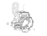
- FIG. 1 is an external view of an in-wheel motor drive device 1 according to an embodiment of the present invention as seen from the front
- FIG. 2 is a side view as seen from the center side of the vehicle body
- FIG. 3 is a drive mechanism housed in a housing 2. It is a schematic sectional drawing which shows.
- the in-wheel motor drive device 1 includes an electric motor 3 that drives wheels, a parallel shaft gear reducer 4 that decelerates and outputs the rotation of the electric motor 3, and a parallel shaft gear reducer 4. And a wheel bearing 5 for transmitting the output to the drive wheels.
- the parallel shaft gear reducer 4 is exemplified, but other reducers such as a planetary gear reducer and a cycloid reducer may be used.
- the electric motor 3 and the parallel shaft gear reducer 4 are housed in the housing 2 and mounted in the wheel housing (not shown) of the electric vehicle.
- the parallel shaft gear reducer 4 is composed of a first gear 6 which is an input gear, a second gear 7 which is an intermediate gear, and a third gear 8 which is an output gear.
- the second gear 7 coaxially has a large diameter tooth portion 9 on the inboard side and a small diameter tooth portion 10 on the outboard side.
- the tooth portion 11 of the first gear 6 and the large diameter tooth portion 9 of the second gear 7 mesh with each other, and the small diameter tooth portion 10 of the second gear 7 and the large diameter tooth of the third gear 8 are engaged.
- the rotation of the electric motor 3 is decelerated at a predetermined reduction ratio.
- the first gear 6 to the third gear 8 are rotatably supported on the housing 2 by rolling bearings 13 to 18.
- the third gear 8 is coaxially attached to the hub wheel 19 of the wheel bearing 5 by spline fitting.
- the electric motor 3 is of a radial gap type, and includes a stator 20 fixed to the housing 2, a rotor 21 arranged radially inward of the stator 20 so as to face each other with a gap, and a radial inner side of the rotor 21.
- a motor rotating shaft 22 that is arranged and rotates integrally with the rotor 21 is provided.
- the stator 20 is configured by winding a coil around the outer circumference of the magnetic core.
- the rotor 21 has a permanent magnet or a magnetic body arranged therein.
- the motor rotating shaft 22 can rotate at a high speed at about 10,000 rotations per minute.
- the motor rotating shaft 22 is rotatably supported with respect to the housing 2 by a rolling bearing 24 at its inboard side end and a rolling bearing 25 at its outboard side end.
- a rotation angle sensor 26 is provided at the end of the motor rotation shaft 22 and the inboard side of the housing 2.
- the shaft portion 27 extending to the outboard side of the motor rotation shaft 22 is coaxially connected to the first gear 6 of the parallel shaft gear reducer 4 by spline fitting.
- the rotation of the electric motor 3 is reduced by the first gear 6 to the third gear 8 of the parallel shaft gear reducer 4 and transmitted to the wheel bearing 5.
- the overall configuration of the in-wheel motor drive device 1 in this embodiment is as described above, and its characteristic configuration will be described in detail below.
- the housing 2 that houses the electric motor 3 and the parallel shaft gear reducer 4 is integrally formed with a conduit 28 that supplies lubricating oil to the lubricated portion.
- the housing 2 is divided at an arbitrary position in consideration of the assembly of internal parts and the like, and in this embodiment, it is divided into three housing members 2a, 2b, 2c in the axial direction.
- a seal material (not shown) is provided on the division surface of the housing 2, that is, on the adjacent joint surfaces of the housing members 2a, 2b, and 2c to prevent leakage of lubricating oil inside the drive device and intrusion of water from the outside. ..
- the dividing surface (sealing surface) of the housing 2 is a single plane.
- An O-ring or a liquid gasket is used as the sealing material.
- the housing 2 is assembled by fastening the outer circumferences of the housing members 2a, 2b, 2c with a plurality of bolts 29 (fastening members).
- the rib 31 does not need to be arranged over the entire length of the conduit 28, but since the rib 31 is for increasing the support rigidity of the mating surface of the conduit 28, it is at least considered in consideration of interference with internal parts and the like.
- the rib height is more than half the length of the pipe 28. Although it is desirable to have a height substantially the same as the length of the conduit 28, in order to avoid contact between the blade and the rib 31 when processing the mating surface of the conduit 28, as shown in FIG. 4 and FIG. 31 should be slightly lower.
- a rib for supporting the conduit 28 may be added.
- the mating surface of the conduit 28 is arranged close to one of the fastening points, the mating surface of the conduit 28 is also given a surface pressure by bolting, which is excellent. A contact state is obtained.
- the surface accuracy of the mating surface of the conduit 28 is improved, and a good contact state can be obtained.
- a sealing material is provided on the mating surface of the conduit 28, but the mating surface of the conduit 28 may be different from the housing sealing surface.
- a liquid gasket is used for the housing sealing surface, and an O-ring 32 having a higher pressure resistance is used for the mating surface of the pipe 28 to which the pumping pressure is applied.
- the mating surface of the conduit 28 and the housing sealing surface may be sealed with the same sealing material. This is because, when the mating surface of the conduit 28 and the sealing surface are arranged close to each other as described above, a sealing material such as a liquid gasket can be arranged by a single coating operation, so that workability is improved and man-hours are reduced.
- the rib 31 that reinforces the conduit 28 is provided so as to extend from the wall surface of the housing members 2a, 2b, 2c, but as in the embodiment shown in FIG. 8, the housing members 2a, 2b, The wall surface 2c itself may be a rib 31 that reinforces the conduit 28.
- FIG. 9 and 10 show the mating surface of the conduit 28 and the mating surface of the housing members 2a, 2b, 2c. As shown in FIG. 9, the conduit 28 should be orthogonal to the mating surface. It is also possible to provide one of the conduits 28 so as to be inclined from the mating surface, as shown in FIG.
- the pipe 28 is a pipe for supplying lubricating oil to the lubricated portion, but the same effect can be obtained even if the structure of the pipe 28 is adopted as a water passage for cooling water or the like.
- the ribs 31 via the ribs 31, even if an external force is applied to the divided housing members 2a, 2b, 2c, the mating surface of the conduit 28 is firmly held and the machining accuracy of the mating surface is improved. It is possible to prevent pressure leakage (liquid leakage) at the connecting portion of the pipeline 28.
- In-wheel motor drive device 2 Housings 2a, 2b, 2c: Housing member 3: Electric motor 4: Parallel shaft gear reducer 5: Wheel bearing 28: Pipe line 29: Bolt (fastening member) 30: Screw hole (fastening point) 31: Rib
Landscapes
- Engineering & Computer Science (AREA)
- General Engineering & Computer Science (AREA)
- Mechanical Engineering (AREA)
- Chemical & Material Sciences (AREA)
- Combustion & Propulsion (AREA)
- Transportation (AREA)
- Arrangement Or Mounting Of Propulsion Units For Vehicles (AREA)
- General Details Of Gearings (AREA)
Abstract
管路を一体成形した分割されたハウジング部材に外力が加わっても管路の合わせ面がしっかりと保持され、管路の接続部の圧力漏れおよび液漏れを防止した車両駆動装置を提供することを課題とする。ハウジング2を分割したハウジング部材2a、2b、2cに一体成形される管路28を、隣り合うハウジング部材2a、2b、2cを締結する二つの締結部材間を繋ぐ位置にリブ31を介して設けることにより、分割されたハウジング部材に外力が加わっても管路28の合わせ面がしっかりと保持されようにした。
Description
この発明は、車両の駆動機構を収容するハウジングが複数のハウジング部材に分割し、その分割したハウジング部材に、潤滑油を被潤滑部へ供給する油路、冷却水の水路等を構成する管路を一体成形した車両駆動装置に関するものである。
自動車等の車両駆動装置においては、被潤滑部に潤滑油を供給するため油路、冷却水の水路等を構成する管路を備えたものが広く使用されている。
従来、車両駆動装置の部品点数および組立工数を削減し、車両駆動装置の小型化を図るために、前記管路を、車両の駆動機構を収容するハウジングに一体成形することが行われている(特許文献1)。
ところで、自動車等の車両駆動装置の駆動機構を収容するハウジングは、内部部品の組立て等を勘案し、複数のハウジング部材に分割されている。分割された隣り合うハウジング部材は、分割面を突き合わせ、ボルト等の複数の締結部材によって締結して組立てられている。
このような複数のハウジング部材に分割されたハウジングにおいては、一体成形される管路も分割されたハウジング部材に設けられる。
したがって、複数のハウジング部材に跨る管路では、ハウジング部材の分割面で管路も分断されるため、分割面で管路の圧力漏れが起こらないようシール材を挟むなどの対策が必要である。特に、足回りに搭載するインホイールモータ駆動装置のハウジングの場合、路面からの入力でハウジングは弾性変形を繰り返すので、旋回走行・前後力・段差乗り上げなど、ハウジング部材の合わせ面がひずんだり引き離される方向に外力を受けた際に、管路の分割面から漏れや圧力漏れを起こさないような対策が重要である。
その対策として、例えば、管路の接続部を内外径で嵌合し、Oリング等でシールすれば圧力漏れが起こり難くすることができるが、管路の接合部を嵌合させようとすれば、管路の接続部に相当の位置精度が要求されることになる。
ところが、ハウジング部材に設けられるモータ軸・ギヤ軸等の駆動軸の取付部分の位置精度は、駆動装置の音・振動、効率および寿命の点で重要であるものの、二つのハウジング部材に跨る管路は、繋がっていれば多少の位置ずれがあっても機能する。
したがって、二つのハウジング部材に跨る管路は、位置精度よりも分割されたハウジング部材に外力が加わっても管路の合わせ面がしっかりと保持されることが重要である。
そこで、この発明は、分割されたハウジング部材に外力が加わっても管路の合わせ面がしっかりと保持されるようにすることを課題とする。
前記の課題を解決するために、この発明は、車両の駆動機構を収容するハウジングを複数のハウジング部材に分割し、分割した隣り合うハウジング部材の分割面を突き合わせて複数の締結部材によって締結し、分割された隣り合うハウジング部材に跨る管路をハウジング部材に一体成形した車両駆動装置において、前記ハウジング部材に一体成形される管路を、隣り合うハウジング部材を締結する二つの締結部材間を繋ぐ位置にリブを介して設けたことを特徴とする。
前記管路を、隣り合うハウジング部材を締結する二つの締結部材の一方に近い位置に設けるようにしてもよい。
前記リブの高さは、前記ハウジング部材の分割面の高さよりも低くしてもよい。
前記ハウジングに収納される車両の駆動機構は、例えば、モータと減速機とからなる。
以上のように、この発明は、ハウジングを分割したハウジング部材に一体成形される管路を、隣り合うハウジング部材を締結する二つの締結部材間を繋ぐ位置にリブを介して設けることにより、分割されたハウジング部材に外力が加わっても管路の合わせ面がしっかりと保持され、また、合わせ面の加工精度も向上することから、管路の接続部の圧力漏れ(液漏れ)を防止できる。
以下、この発明の実施の形態を添付図面に基づいて説明する。
図1は、この発明の実施形態に係るインホイールモータ駆動装置1を正面から見た外観図、図2は車体の中央側から見た側面図、図3はハウジング2内に収納された駆動機構を示す概略断面図である。
ハウジング2は、図1に示すように、軸方向に3つのハウジング部材2a、2b、2cに分割されている。
インホイールモータ駆動装置1は、図3に示すように、車輪を駆動する電動モータ3と、電動モータ3の回転を減速して出力する平行軸歯車減速機4と、平行軸歯車減速機4の出力を駆動輪に伝達する車輪用軸受5とを備えている。なお、この実施形態では、平行軸歯車減速機4を例示するが、例えば、遊星歯車減速機やサイクロイド減速機など他の減速機であってもよい。
電動モータ3と平行軸歯車減速機4は、ハウジング2に収容され、電気自動車のホイールハウジング(図示省略)内に取り付けられる。
平行軸歯車減速機4は、入力歯車である第1歯車6と、中間歯車である第2歯車7と、出力歯車である第3歯車8とで構成されている。第2歯車7は、インボード側の大径歯部9とアウトボード側の小径歯部10とを同軸的に有する。
平行軸歯車減速機4は、第1歯車6の歯部11と第2歯車7の大径歯部9とが噛合し、第2歯車7の小径歯部10と第3歯車8の大径歯部12とが噛合することにより、電動モータ3の回転を所定の減速比で減速するものである。
第1歯車6~第3歯車8は、転がり軸受13~18によってハウジング2に回転自在に支持されている。第3歯車8は、車輪用軸受5のハブ輪19にスプライン嵌合により同軸的に取り付けられている。
電動モータ3は、ラジアルギャップ型であり、ハウジング2に固定されたステータ20と、そのステータ20の径方向内側に隙間をもって対向するように配置されたロータ21と、そのロータ21の径方向内側に配置されてロータ21と一体回転するモータ回転軸22とを備えている。
ステータ20は、磁性体コアの外周にコイルを巻回することによって構成されている。ロータ21は、永久磁石または磁性体が内部に配置されている。モータ回転軸22は、毎分一万数千回転程度で高速回転可能である。
モータ回転軸22は、そのインボード側端部が転がり軸受24に、アウトボード側端部が転がり軸受25によって、ハウジング2に対して回転自在に支持されている。
モータ回転軸22およびハウジング2のインボード側端部には回転角センサ26が設けられている。モータ回転軸22のアウトボード側に延在する軸部27は、平行軸歯車減速機4の第1歯車6にスプライン嵌合により同軸的に連結されている。
なお、この実施形態では、ラジアルギャップ型の電動モータ3を例示したが、任意の構成のモータを適用可能である。例えば、ケーシングに固定されたステータと、そのステータの軸方向内側に隙間をもって対向するように配置されたロータとを備えるアキシャルギャップ型の電動モータであってもよい。
以上の構成からなるインホイールモータ駆動装置1では、電動モータ3の回転が平行軸歯車減速機4の第1歯車6~第3歯車8によって減速され、車輪用軸受5に伝達される。
この実施形態におけるインホイールモータ駆動装置1の全体構成は、以上のとおりであり、その特徴的な構成を以下に詳述する。
電動モータ3と平行軸歯車減速機4を収めるハウジング2に、被潤滑部に潤滑油を供給する管路28を一体成形する。ハウジング2は、前述のように、内部部品の組み立て等を勘案し、任意の位置で分割されており、この実施形態では、軸方向に3つのハウジング部材2a、2b、2cに分割している。
ハウジング2の分割面、即ち、ハウジング部材2a、2b、2cの隣り合う接合面には駆動装置内部の潤滑油の漏れや外部からの水の浸入を防ぐシール材(図示省略)が設けられている。ハウジング2の分割面(シール面)は単一平面である。シール材はOリングや液状ガスケットを使用する。
ハウジング部材2a、2b、2cは、外周を複数のボルト29(締結部材)で締結してハウジング2が組み立てられる。
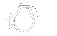
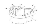
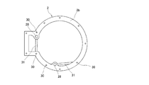
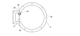
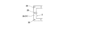
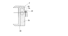
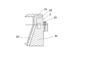
管路28の合わせ面は、図4及び図5に示すように、ハウジング部材2a、2b、2cの分割面と同一平面上にある。ハウジング部材2a、2b、2cの分割面には、ボルト29(締結部材)を締結する複数のねじ穴30(締結点)が設けられ、このうち二つの締結点を結ぶ線上に管路28が配置され、管路28と二つの締結点との間をリブ31で繋いで補強している。
リブ31は、管路28の全長に亘って配置する必要はないが、リブ31は管路28の合わせ面の支持剛性を高めるためのものであるから、内部部品との干渉等を勘案し少なくとも管路28の長さの半分以上のリブ高さを持たせている。管路28の長さとほぼ同じ高さを持つことが望ましいが、管路28の合わせ面加工時に刃物とリブ31との接触を避けるため、図4及び図5に示すように、合わせ面よりリブ31が若干低くなるようにするとよい。
前記二つの締結点を結ぶ線上のリブ31に加え、管路28を支持するリブを増設してもよい。
また、図6または図7に示すように、管路28の合わせ面をいずれかの締結点に近づけて配置すれば、管路28の合わせ面にもボルト締結による面圧が付与され、良好な接触状態が得られる。
通常、締結点はシール面上もしくはそのごく近くに設けられるため、シール面と管路28の合わせ面も近づくことになって両平面の同時加工が可能となり、シール面(=ハウジング分割面)に対する管路28の合わせ面の面精度が向上し、良好な接触状態が得られる。
また、管路28の合わせ面にもシール材を設けるようにするが、管路28の合わせ面はハウジングシール面と別のシール材を使用しても良い。例えば、ハウジングシール面に液状ガスケットを使用し、圧送圧力の加わる管路28の合わせ面には、より耐圧性能の高いOリング32を使用するなどである。
また、管路28の合わせ面とハウジングシール面とを同一のシール材でシールしても良い。これは、前記のように管路28の合わせ面とシール面を近づけて配置したとき、液状ガスケットなどのシール材を一度の塗布動作で配置できるため、作業性向上や工数削減効果がある。
以上の実施形態では、管路28を補強するリブ31をハウジング部材2a、2b、2cの壁面から延長するように設けているが、図8に示す実施形態のように、ハウジング部材2a、2b、2cの壁面自体が管路28を補強するリブ31になっていてもよい。
なお、図9および図10は、管路28の合わせ面とハウジング部材2a、2b、2cの合わせ面を示しており、図9に示すように、管路28は合わせ面に対して直交するように設けてもよいし、図10に示すように、一方の管路28を合わせ面から傾斜するように設けてもよい。
前記管路28は、被潤滑部に潤滑油を供給する配管であるが、この管路28の構造は冷却水の水路等に採用しても同様の効果が得られる。
以上のように、前記ハウジング部材2a、2b、2cに一体成形される管路28を、隣り合うハウジング部材2a、2b、2cを締結する二つのボルト29(=ねじ穴30)間を繋ぐ位置にリブ31を介して設けることにより、分割されたハウジング部材2a、2b、2cに外力が加わっても管路28の合わせ面がしっかりと保持され、また、合わせ面の加工精度も向上することから、管路28の接続部の圧力漏れ(液漏れ)を防止できる。
この発明は前述した実施形態に何ら限定されるものではなく、この発明の要旨を逸脱しない範囲において、さらに種々の形態で実施し得ることは勿論のことであり、本発明の範囲は、特許請求の範囲によって示され、さらに特許請求の範囲に記載の均等の意味、および範囲内の全ての変更を含む。
1 :インホイールモータ駆動装置
2 :ハウジング
2a、2b、2c :ハウジング部材
3 :電動モータ
4 :平行軸歯車減速機
5 :車輪用軸受
28 :管路
29 :ボルト(締結部材)
30 :ねじ穴(締結点)
31 :リブ
2 :ハウジング
2a、2b、2c :ハウジング部材
3 :電動モータ
4 :平行軸歯車減速機
5 :車輪用軸受
28 :管路
29 :ボルト(締結部材)
30 :ねじ穴(締結点)
31 :リブ
Claims (4)
- 車両の駆動機構を収容するハウジングが複数のハウジング部材に分割され、分割された隣り合うハウジング部材の分割面を突き合わせて複数の締結部材によって締結し、分割された隣り合うハウジング部材に跨る管路をハウジング部材に一体成形した車両駆動装置において、前記ハウジング部材に一体成形される管路を、隣り合うハウジング部材を締結する二つの締結部材間を繋ぐ位置にリブを介して設けたことを特徴とする車両駆動装置。
- 前記管路が隣り合うハウジング部材を締結する二つの締結部材の一方に近い位置に設けられていることを特徴とする請求項1記載の車両駆動装置。
- 前記リブの高さが前記ハウジング部材の分割面の高さよりも低いことを特徴とする請求項1または2記載の車両駆動装置。
- 前記ハウジングに収納される車両の駆動機構が、モータと減速機からなる請求項1~3のいずれかの項に記載の車両駆動装置。
Priority Applications (2)
| Application Number | Priority Date | Filing Date | Title |
|---|---|---|---|
| CN201980081931.XA CN113167371A (zh) | 2018-12-14 | 2019-12-02 | 车辆驱动装置 |
| EP19895341.6A EP3896310A4 (en) | 2018-12-14 | 2019-12-02 | VEHICLE DRIVE DEVICE |
Applications Claiming Priority (2)
| Application Number | Priority Date | Filing Date | Title |
|---|---|---|---|
| JP2018-234010 | 2018-12-14 | ||
| JP2018234010A JP2020094656A (ja) | 2018-12-14 | 2018-12-14 | 車両駆動装置 |
Publications (1)
| Publication Number | Publication Date |
|---|---|
| WO2020121863A1 true WO2020121863A1 (ja) | 2020-06-18 |
Family
ID=71076954
Family Applications (1)
| Application Number | Title | Priority Date | Filing Date |
|---|---|---|---|
| PCT/JP2019/046974 Ceased WO2020121863A1 (ja) | 2018-12-14 | 2019-12-02 | 車両駆動装置 |
Country Status (4)
| Country | Link |
|---|---|
| EP (1) | EP3896310A4 (ja) |
| JP (1) | JP2020094656A (ja) |
| CN (1) | CN113167371A (ja) |
| WO (1) | WO2020121863A1 (ja) |
Citations (2)
| Publication number | Priority date | Publication date | Assignee | Title |
|---|---|---|---|---|
| JPS61105362A (ja) * | 1984-10-30 | 1986-05-23 | Nissan Motor Co Ltd | 変速機のオイルポンプ |
| JP2015166620A (ja) * | 2014-03-04 | 2015-09-24 | トヨタ自動車株式会社 | 駆動装置 |
Family Cites Families (6)
| Publication number | Priority date | Publication date | Assignee | Title |
|---|---|---|---|---|
| JPH04277360A (ja) * | 1991-02-28 | 1992-10-02 | Suzuki Motor Corp | 歯車変速機における潤滑構造 |
| JP5630581B2 (ja) * | 2011-07-19 | 2014-11-26 | トヨタ自動車株式会社 | 車両用駆動装置 |
| US20140311268A1 (en) * | 2013-04-22 | 2014-10-23 | Thomas Großwald | Oiling device for an axle with spur gear |
| JP6130285B2 (ja) * | 2013-11-08 | 2017-05-17 | 本田技研工業株式会社 | 変速機取付構造 |
| JP2015231275A (ja) * | 2014-06-04 | 2015-12-21 | Ntn株式会社 | インホイールモータ駆動装置 |
| JP6138106B2 (ja) * | 2014-11-27 | 2017-05-31 | アイシン精機株式会社 | 減速機の潤滑構造 |
-
2018
- 2018-12-14 JP JP2018234010A patent/JP2020094656A/ja active Pending
-
2019
- 2019-12-02 CN CN201980081931.XA patent/CN113167371A/zh active Pending
- 2019-12-02 WO PCT/JP2019/046974 patent/WO2020121863A1/ja not_active Ceased
- 2019-12-02 EP EP19895341.6A patent/EP3896310A4/en not_active Withdrawn
Patent Citations (2)
| Publication number | Priority date | Publication date | Assignee | Title |
|---|---|---|---|---|
| JPS61105362A (ja) * | 1984-10-30 | 1986-05-23 | Nissan Motor Co Ltd | 変速機のオイルポンプ |
| JP2015166620A (ja) * | 2014-03-04 | 2015-09-24 | トヨタ自動車株式会社 | 駆動装置 |
Non-Patent Citations (1)
| Title |
|---|
| See also references of EP3896310A4 * |
Also Published As
| Publication number | Publication date |
|---|---|
| JP2020094656A (ja) | 2020-06-18 |
| EP3896310A4 (en) | 2022-09-14 |
| CN113167371A (zh) | 2021-07-23 |
| EP3896310A1 (en) | 2021-10-20 |
Similar Documents
| Publication | Publication Date | Title |
|---|---|---|
| JP5685111B2 (ja) | 電気自動車用駆動装置 | |
| JP5685112B2 (ja) | 電気自動車用駆動装置 | |
| JP5685113B2 (ja) | 電気自動車用駆動装置 | |
| US8002060B2 (en) | Vehicle wheel driving apparatus and electric motor | |
| JP5604338B2 (ja) | 電気自動車用駆動装置 | |
| JP5676314B2 (ja) | 電気自動車用駆動装置 | |
| JP2013071698A (ja) | 電気自動車用駆動装置 | |
| CN108626355B (zh) | 轮内电动机单元 | |
| KR101786197B1 (ko) | 감속기 일체형 모터 | |
| JP2016136822A (ja) | 駆動装置 | |
| WO2020121863A1 (ja) | 車両駆動装置 | |
| US10378642B2 (en) | Passive lubrication system for concentric gear drive for an electric vehicle | |
| JP5956552B2 (ja) | 電気自動車用駆動装置 | |
| US12594825B2 (en) | In-wheel motor driving device | |
| WO2021095674A1 (ja) | インホイールモータ駆動装置 | |
| JP2003158851A (ja) | 車両用モータの配線接続装置 | |
| JP2013040659A (ja) | 電気自動車用駆動装置 | |
| JP2016141199A (ja) | 車両の駆動装置 |
Legal Events
| Date | Code | Title | Description |
|---|---|---|---|
| 121 | Ep: the epo has been informed by wipo that ep was designated in this application |
Ref document number: 19895341 Country of ref document: EP Kind code of ref document: A1 |
|
| NENP | Non-entry into the national phase |
Ref country code: DE |
|
| ENP | Entry into the national phase |
Ref document number: 2019895341 Country of ref document: EP Effective date: 20210714 |