WO2020121880A1 - 膜欠陥検査方法及び膜欠陥検査装置 - Google Patents
膜欠陥検査方法及び膜欠陥検査装置 Download PDFInfo
- Publication number
- WO2020121880A1 WO2020121880A1 PCT/JP2019/047119 JP2019047119W WO2020121880A1 WO 2020121880 A1 WO2020121880 A1 WO 2020121880A1 JP 2019047119 W JP2019047119 W JP 2019047119W WO 2020121880 A1 WO2020121880 A1 WO 2020121880A1
- Authority
- WO
- WIPO (PCT)
- Prior art keywords
- membrane
- gas
- gas detection
- pipe
- defect inspection
- Prior art date
- Legal status (The legal status is an assumption and is not a legal conclusion. Google has not performed a legal analysis and makes no representation as to the accuracy of the status listed.)
- Ceased
Links
Images

Classifications
-
- B—PERFORMING OPERATIONS; TRANSPORTING
- B01—PHYSICAL OR CHEMICAL PROCESSES OR APPARATUS IN GENERAL
- B01D—SEPARATION
- B01D65/00—Accessories or auxiliary operations, in general, for separation processes or apparatus using semi-permeable membranes
- B01D65/10—Testing of membranes or membrane apparatus; Detecting or repairing leaks
- B01D65/104—Detection of leaks in membrane apparatus or modules
-
- B—PERFORMING OPERATIONS; TRANSPORTING
- B01—PHYSICAL OR CHEMICAL PROCESSES OR APPARATUS IN GENERAL
- B01D—SEPARATION
- B01D65/00—Accessories or auxiliary operations, in general, for separation processes or apparatus using semi-permeable membranes
- B01D65/10—Testing of membranes or membrane apparatus; Detecting or repairing leaks
- B01D65/102—Detection of leaks in membranes
-
- G—PHYSICS
- G01—MEASURING; TESTING
- G01M—TESTING STATIC OR DYNAMIC BALANCE OF MACHINES OR STRUCTURES; TESTING OF STRUCTURES OR APPARATUS, NOT OTHERWISE PROVIDED FOR
- G01M3/00—Investigating fluid-tightness of structures
- G01M3/02—Investigating fluid-tightness of structures by using fluid or vacuum
- G01M3/04—Investigating fluid-tightness of structures by using fluid or vacuum by detecting the presence of fluid at the leakage point
- G01M3/06—Investigating fluid-tightness of structures by using fluid or vacuum by detecting the presence of fluid at the leakage point by observing bubbles in a liquid pool
- G01M3/08—Investigating fluid-tightness of structures by using fluid or vacuum by detecting the presence of fluid at the leakage point by observing bubbles in a liquid pool for pipes, cables or tubes; for pipe joints or seals; for valves; for welds
- G01M3/085—Investigating fluid-tightness of structures by using fluid or vacuum by detecting the presence of fluid at the leakage point by observing bubbles in a liquid pool for pipes, cables or tubes; for pipe joints or seals; for valves; for welds for pipe joints or seals
-
- G—PHYSICS
- G01—MEASURING; TESTING
- G01M—TESTING STATIC OR DYNAMIC BALANCE OF MACHINES OR STRUCTURES; TESTING OF STRUCTURES OR APPARATUS, NOT OTHERWISE PROVIDED FOR
- G01M3/00—Investigating fluid-tightness of structures
- G01M3/02—Investigating fluid-tightness of structures by using fluid or vacuum
- G01M3/04—Investigating fluid-tightness of structures by using fluid or vacuum by detecting the presence of fluid at the leakage point
- G01M3/24—Investigating fluid-tightness of structures by using fluid or vacuum by detecting the presence of fluid at the leakage point using infrasonic, sonic or ultrasonic vibrations
-
- G—PHYSICS
- G01—MEASURING; TESTING
- G01M—TESTING STATIC OR DYNAMIC BALANCE OF MACHINES OR STRUCTURES; TESTING OF STRUCTURES OR APPARATUS, NOT OTHERWISE PROVIDED FOR
- G01M3/00—Investigating fluid-tightness of structures
- G01M3/02—Investigating fluid-tightness of structures by using fluid or vacuum
- G01M3/04—Investigating fluid-tightness of structures by using fluid or vacuum by detecting the presence of fluid at the leakage point
- G01M3/24—Investigating fluid-tightness of structures by using fluid or vacuum by detecting the presence of fluid at the leakage point using infrasonic, sonic or ultrasonic vibrations
- G01M3/243—Investigating fluid-tightness of structures by using fluid or vacuum by detecting the presence of fluid at the leakage point using infrasonic, sonic or ultrasonic vibrations for pipes
-
- B—PERFORMING OPERATIONS; TRANSPORTING
- B01—PHYSICAL OR CHEMICAL PROCESSES OR APPARATUS IN GENERAL
- B01D—SEPARATION
- B01D2313/00—Details relating to membrane modules or apparatus
- B01D2313/60—Specific sensors or sensor arrangements
-
- B—PERFORMING OPERATIONS; TRANSPORTING
- B01—PHYSICAL OR CHEMICAL PROCESSES OR APPARATUS IN GENERAL
- B01D—SEPARATION
- B01D2313/00—Details relating to membrane modules or apparatus
- B01D2313/70—Control means using a programmable logic controller [PLC] or a computer
-
- B—PERFORMING OPERATIONS; TRANSPORTING
- B01—PHYSICAL OR CHEMICAL PROCESSES OR APPARATUS IN GENERAL
- B01D—SEPARATION
- B01D2313/00—Details relating to membrane modules or apparatus
- B01D2313/90—Additional auxiliary systems integrated with the module or apparatus
- B01D2313/903—Integrated control or detection device
-
- B—PERFORMING OPERATIONS; TRANSPORTING
- B01—PHYSICAL OR CHEMICAL PROCESSES OR APPARATUS IN GENERAL
- B01D—SEPARATION
- B01D2321/00—Details relating to membrane cleaning, regeneration, sterilization or to the prevention of fouling
- B01D2321/18—Use of gases
Definitions
- the present invention provides a membrane module set in which a plurality of membrane modules are connected in parallel below a gas detection pipe that communicates with a primary side space to which raw water is supplied or a secondary side space from which treated water obtained by membrane filtration of raw water is taken out.
- the present invention relates to a membrane defect inspection method for a membrane separation device having a plurality of.
- Patent Document 1 the inside of the casing is divided into a raw water chamber, a circulating water chamber and a treated water chamber that communicate with the raw water chamber, and a large number of hollow fiber membranes for communicating the treated water chamber and the circulating water chamber are provided.
- the treated water is sent to the outside through the hollow fiber membrane and the treated water chamber, the raw water chamber and the circulating water chamber are emptied, and the treated water only in the treated water chamber.
- a pressurized gas is blown to the outside of the hollow fiber membrane, and bubbles generated on the treated water chamber side are detected to detect breakage of the hollow fiber membrane.
- a method for detecting breakage of the permeable membrane module has been proposed.
- Patent Document 2 discloses a water treatment filtration system in which raw water is supplied to a membrane module and treated water purified by the membrane module is distributed to a primary side or a secondary side of the membrane module under a predetermined pressure. And a vibration detection sensor that is attached to the upper part of the membrane module and that detects vibration due to a bubble flow that leaks from a damaged portion of the membrane and rises in water.
- a membrane damage of a filtration system for water treatment comprising: a vibration analysis processing device which individually selects a vibration signal to be detected and detects the membrane damage of the membrane module by analyzing the vibration signal. Detection devices have been proposed.
- Patent Document 3 a transparent liquid is used to form a part of a pipe in which the filtrate is circulated or stagnant on the flow path, in which the raw liquid is supplied from one of the outside and the inside of the hollow fiber membrane and the filtrate is taken out from the other. Is supplied from one of the outer side or the inner side of the hollow fiber membrane and is taken out as a filtrate from the other side by supplying air to the flow path to break the membrane in the hollow fiber membrane when the air bubbles of the air pass through the transparent tube.
- a membrane breakage detection method for hollow fiber membranes has been proposed, which is characterized by detecting the occurrence of the occurrence.
- Patent Document 1 requires the use of an ultrasonic velocity meter to detect bubbles, and an ultrasonic velocity meter is installed in a straight pipe of a predetermined length to establish an appropriate detection environment. However, it was not possible to attach it to any water purification device because of the installation restriction that it was necessary to do so.
- the membrane damage detection device described in Patent Document 2 requires a large number of vibration detection sensors to attach a vibration detection sensor to each membrane module, and since the membrane module has a strong structure with pressure resistance, vibration detection is performed.
- the vibration signal detected by the sensor becomes weak, and there is a problem that the detection accuracy is low due to the influence of noise such as external vibration.
- an object of the present invention is to automate the detection of breakage of a filtration membrane, and to appropriately detect the presence or absence of breakage or sealing failure of a membrane module and a membrane defect inspection apparatus. Is in the point of providing.
- the first characteristic configuration of the membrane defect inspection method for a membrane module set according to the present invention is the primary space of a membrane module to which raw water is supplied or treated water obtained by membrane filtration of raw water is taken out.
- the second characteristic configuration is that a plurality of gas detection pipes communicating with the primary side space of the membrane module to which raw water is supplied or the secondary side space of the membrane module from which treated water obtained by membrane filtration of raw water is taken out A method for inspecting a membrane defect of a membrane module set in which membrane modules are connected in parallel, wherein the gas detection pipe of the membrane module communicates with the primary space or the secondary side in a state where the gas detection pipe is filled with water.
- the gas detection pipe will be damaged when bubbles rise in the gas detection pipe and collide with the inner wall.
- the generated vibration is reliably transmitted to the vibration sensor. Further, since it is extended in the axial direction of the gas detection pipe, no special restrictions are imposed on the connection structure between the gas detection pipe and multiple membrane modules, and the freedom of mounting the vibration sensor is secured. can do.
- the third characteristic configuration is, in addition to the above-mentioned second characteristic configuration, that the projecting portion is a short pipe extending from the end of the gas detection pipe in the axial direction of the gas detection pipe. is there.
- a vibration sensor can be attached to both the inner circumference and the outer circumference of the short pipe, especially the inner circumference of the short pipe.
- the short tube itself functions as a protection member for the vibration sensor.
- the fourth characteristic configuration is that, in addition to any one of the first to third characteristic configurations described above, the gas detection pipe is made of resin.
- the gas detection pipe is made of resin, air bubbles will rise to the gas detection pipe and, when colliding with the inner wall, the vibrations that occur in the gas detection pipe will propagate to the protrusion without being significantly damped, and sufficient detection accuracy will be achieved. Is obtained.
- the first characteristic configuration of the membrane defect inspection method for a membrane separation device is a membrane defect inspection method for a membrane separation device comprising a plurality of membrane module sets in which a plurality of membrane modules are connected in parallel below the gas detection pipe.
- the gas released to the gas detection pipe in the entire membrane separation device is collected, in a state in which the gas detection large pipe communicating with the gas detection pipe is filled with water, the gas injection step is performed, A gas storage detection step of detecting that gas is stored in the gas detection large pipe; and when detecting that gas is stored in the gas storage detection step, the above-mentioned first to fourth
- the point is to perform a film defect inspection method for a film module set having any one of the characteristic configurations.
- the gas detection large pipe in addition to the above-mentioned first characteristic configuration, at least a part of the gas detection large pipe is transparent, and in the gas storage detection step, observation is performed at a transparent portion of the gas detection large pipe. The point is that the gas storage is detected by detecting the gas-liquid interface formed by image analysis.
- the state of that part can be visually confirmed, and it can be detected visually that the gas is stored. It becomes possible to make an automatic determination by image analysis of.
- the characteristic configuration of the film defect inspection apparatus for a film module set according to the present invention is a film defect inspection apparatus for performing the film defect inspection method for a film module set having any one of the above-described first to fourth characteristic configurations. Therefore, a plurality of membrane modules are connected in parallel below the gas detection pipe that communicates with the primary side space of the membrane module to which raw water is supplied or the secondary side space of the membrane module from which treated water obtained by membrane filtration of raw water is taken out.
- the gas detection in the gas press-fitting step based on the membrane module set, the protrusion provided in the gas detection pipe, the vibration sensor attached to the protrusion, and the vibration signal detected by the vibration sensor. And a signal processing unit that detects the inflow of gas into the pipe.
- the present invention it is possible to automate the detection of the breakage of the filtration membrane, and to provide the film defect inspection method and the film defect inspection apparatus which can appropriately detect the presence or absence of the breakage or the sealing failure of the membrane module. I was able to do it.
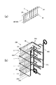
- FIG. 1A is a front view showing the membrane module set
- FIG. 1B is a left side view showing the membrane module set
- FIG. 2A is a schematic diagram of a membrane module set
- FIG. 2B is a schematic diagram of a membrane separation device including a plurality of membrane module sets.
- FIG. 3A and FIG. 3B are explanatory views of the vibration sensor arranged in contact with the protruding portion of the treated water pipe.
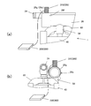
- FIG. 4A shows a defect inspection method for the membrane separation device, and is an explanatory view of the inspection device attached to the filtered water large pipe of the membrane separation device
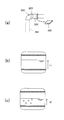
- FIG. 4B shows a defect inspection method for the membrane separation device.
- 4C is an explanatory diagram of an inspection image at the time of normality
- FIG. 4C is an explanatory diagram of an inspection image at the time of abnormality, showing a defect inspection method for the membrane separation device.
- FIG. 1A and 1B illustrate a film module set 1 to which the film defect inspection method according to the present invention is applied.
- the membrane module set 1 includes eight membrane modules 20, a raw water header pipe 22 that is a raw water supply pipe that supplies raw water to each membrane module 20, and a cleaning air or water or chemical solution that is supplied to each membrane module 20.
- a cleaning header pipe 24 that is an air pipe and a filtered water header pipe 26 that is a treated water pipe that collects the filtered water of each membrane module 20 are provided.
- Each membrane module 20 is composed of a membrane casing 100 and a membrane element 2 (shown by a chain line in FIG. 1B) housed in the membrane casing 100.
- the membrane casing 100 includes a base 30 and a base 30.
- the casing body 40, the upper lid body 50, the support portion 60 supported by the casing body 40, and the relative position of the support portion 60 and the upper lid body 50 is adjustable and held along the axial direction of the casing body 40.
- the holding unit 70 and the like are provided.
- the membrane element 2 is housed in the casing body 40 in a state where the membrane element 2 is pressed between the base 30 and the upper lid 50 via the seal members P respectively.
- the raw water supplied from the raw water header pipe 22 is filtered by the membrane element 2, and the filtered water passes through the gap between the inner wall of the casing body 40 and the membrane element 2 and is filtered from the filtered water outflow pipe 54 formed in the upper lid 50. Water is collected in the header pipe 26.
- the base 30, the casing body 40, the upper lid 50, the support portion 60, the holding portion 70, and the like may be made of metal, resin, or the like as long as they can withstand the pressure of the filtration process and the cleaning process, and the filtered water header pipe 26
- the piping such as is made of a resin suitable for workability and a film breakage inspection described later, such as ABS resin or polyvinyl chloride resin.
- the membrane element 2 can be any filtration membrane such as a microfiltration membrane, an ultrafiltration membrane, or a nanofiltration membrane that blocks particles or macromolecules of a predetermined size depending on the application, and the material of the membrane is cellulose acetate or polyimide. It is possible to use an organic film such as a hollow fiber film made of, for example, or a porous inorganic film made of a ceramic material.
- the filtration step in which foreign matter is removed by the filtration membrane layer on the inner wall of the fluid passage hole formed in the membrane element 2 proceeds and flows out from the surface of the membrane element 2.
- the filtered water is guided to the filtered water outflow pipe 54 through the space formed between the peripheral surface of the membrane element 2 and the inner wall surface of the casing body 40, and is collected in the filtered water header pipe 26.
- a plurality of membrane modules 20, eight membrane modules 20 in the present embodiment, are connected in parallel below the straight pipe portion of the filtered water header pipe 26 that is a treated water pipe extending in the horizontal direction to form the membrane module set 1. There is.
- FIG. 2A shows a simplified schematic view of the above-mentioned membrane module set 1
- FIG. 2B shows a membrane module set 1 in which a plurality of membrane modules 20 are connected in parallel to a filtered water header pipe 26.
- the schematic diagram of the membrane separation apparatus 200 provided with two or more is shown.
- Eight membrane module sets 1 are installed per stage in a frame that has a vertically long rectangular parallelepiped and is configured in four stages in the vertical direction.
- the raw water header pipe 22, the washing header pipe 24, and the filtered water of each membrane module set 1 are installed.
- Each of the header pipes 26 is connected to a large raw water pipe 22C, a large washing pipe 24C, and a large filtered water pipe 26C which is a large treated water pipe via relay pipes 22A, 24A, 26A.
- the filtered water header pipe 26 functions as a gas detection pipe
- the filtered water large pipe 26A functions as a gas detection large pipe.
- a pipe end portion 26e on the side opposite to the side connected to the filtered water large pipe 26A has a diameter slightly different from the pipe end surface 26f.
- a large flange portion 26g for pipe connection is formed to extend.
- the flange portion 26g is a short pipe extending in the axial direction of the treated water pipe 26.
- the film defect inspection apparatus 300 is composed of a vibration sensor 310 and a signal processing unit 320.
- the vibration sensor 310 is arranged in contact with the outer surface of the flange portion 26g, and is connected to the signal processing unit 320 by a signal line.
- the filtered water header pipe 26 is filled with water and vibrates on the outer surface of the flange portion 26g in a state where air is press-fitted into the membrane element 2 from the raw water header pipe 22 communicating with the primary side space of the membrane module to which raw water is supplied.
- gas is introduced into the secondary side space of the membrane module from which the treated water filtered by the filter membrane is taken out from the defective portion. Gas leaks and gas flows into the filtered water header pipe 26.
- gas flows into the water filled in the filtered water header pipe 26 as bubbles when the bubbles rise in the filtered water header pipe 26 and collide with the upper portion of the inner wall, vibration occurs in the filtered water header pipe 26.
- the flange portion 26g which is a protruding portion provided in the filtered water header pipe 26, serves as a vibration detection piece that transmits the vibration of the filtered water header pipe 26, and the vibration sensor 310 is brought into contact with the flange portion 26g, whereby the filtered water header pipe 26 It is possible to determine that there is a defective portion in the filtration membrane contained in one of the membrane modules 20 connected to the filtered water header pipe 26 due to the vibration.
- the vibration signal detected by the vibration sensor is input to the signal processing unit via the signal line, and after the amplification processing, the vibration period and amplitude are obtained, and it is determined whether or not the vibration is due to gas leakage. To be done. If the vibration is due to gas leakage, the vibration is randomly detected, and it is identified as a simple mechanical shock from the outside.
- the filtered water header pipe 26 which is the treated water pipe, be made of resin that has excellent vibration transmission characteristics. Therefore, the filtered water header pipe 26 is made of a resin pipe member such as ABS resin or polyvinyl chloride resin. Then, by bringing the vibration sensor 310 into contact with the protruding portion protruding outward from the filtered water header pipe 26, it is possible to appropriately detect the vibration caused by the gas leakage.
- the protrusion with which the vibration sensor is arranged in contact is preferably a short pipe extending from the end of the filtered water header pipe 26 in the axial direction of the filtered water header pipe 26, but it is not always short.
- the pipe need not be a pipe, and may be a plate-shaped projecting piece extending from the end of the filtered water header pipe 26 in the axial direction of the filtered water header pipe 26.
- at least a projecting piece projecting outward from the outer surface of the filtered water header tube 26, which is a projecting piece capable of transmitting the vibration of the filtered water header tube 26, extends in the axial direction of the filtered water header tube 26. It is not limited to the mode described.
- the film defect inspection device 300 is incorporated in all of the film module set 1, the economy may be impaired. Therefore, the membrane defect inspection method of the membrane separation device 200 described below is executed, and when an abnormality is detected in any of the membrane module sets 1, the membrane defect inspection method for each membrane module set 1 is manually executed. With such a configuration, economic efficiency is improved.
- the membrane defect inspection method of the membrane separation device 200 at least a part of the treated water large pipe 26C from which the treated water obtained in the entire membrane separation device 200 is taken out is transparent, and the treated water large pipe 26C is filled with water.
- the gas is injected into the raw water supply side which is the primary space of the membrane separation device 200, that is, the raw water large piping pipe 22C, and the transparent portion of the treated water large pipe 26C which is the secondary space is filled with gas.
- a gas storage detecting step of detecting that the gas is stored. When the storage of gas is detected in the gas storage detecting step, the above-described film defect inspection method of the film module set 1C is performed.
- a part of the horizontal pipe flange-connected from the curved pipe at the upper end of the large treated water pipe 26C is configured by a transparent resin pipe 26D, and the transparent resin pipe 26D is placed in a horizontal posture. It is preferable to install an image pickup device 330 for photographing the inside of the tube.
- the leaked air bubbles flow into the transparent resin tube 26D and rise, and the water level changes.
- the image processing device 340 By analyzing the image including the gas-liquid interface captured by the image capturing device 330 by the image processing device 340, when a decrease in the water surface is detected, it can be determined that one of the membrane modules 20 is out of order. Become.
- a computer device in which image analysis software is installed can be preferably used as the image processing device 340, and the gas-liquid interface can be extracted by executing edge extraction processing or the like on the captured image, for example.
- the image processing device 340 installed at a remote place can analyze the image.
- the variation of the gas-liquid interface may be observed by directly visually confirming the transparent resin tube 26D without using the imaging device 330 or the image processing device 340.
- the filtered water header pipe 26 is located above the membrane module, and the filtered water header pipe 26 is used as a gas detection pipe.
- the raw water header pipe 22 is used as a gas detection pipe and the raw water large pipe 22C is used as a gas detection large pipe by injecting gas into the secondary side space of the membrane module.
- gas may be press-fitted from the filtered water extraction side of the membrane module, a protrusion may be provided at the end of the raw water supply pipe, and the vibration sensor may be placed in contact with the protrusion.
- the cleaning air pipe can be used as the gas detection pipe and the cleaning large pipe 24C can be used as the gas detection large pipe, and the gas detection pipe dedicated to the film defect inspection and the gas detection large pipe can be used. It can be provided separately.
- the method for inspecting a membrane defect according to the present invention is provided below a gas detection pipe which communicates with a primary side space of a membrane module to which raw water is supplied or a secondary side space of a membrane module from which treated water obtained by membrane filtration of raw water is taken out.
- the gas injection step of injecting gas into the space opposite to the secondary side space, and the gas detection pipe having a protruding portion protruding outward, and bringing the vibration sensor into contact with the protruding portion A vibration detection step of detecting vibration caused by the gas flowing into the gas detection pipe through the defective portion of the filtration membrane in the step.
- Membrane module set 2 Membrane element 20: Membrane module 22: Raw water header pipe (raw water supply pipe) 24: Wash header pipe (wash air pipe) 26: (Processed water pipe) Filtered water header pipe 26C: (Large treated water pipe) Large filtered water pipe 40: Casing (main body) 50: Casing (upper lid) 54: filtered water outflow pipe 60: support part 300: membrane defect inspection device 310: vibration sensor 320: signal processing part
Landscapes
- Chemical & Material Sciences (AREA)
- Chemical Kinetics & Catalysis (AREA)
- Physics & Mathematics (AREA)
- General Physics & Mathematics (AREA)
- Separation Using Semi-Permeable Membranes (AREA)
- Examining Or Testing Airtightness (AREA)
Abstract
ろ過膜の破断検知の自動化が可能で、膜モジュールの破断やシール不良の有無を適切に検出することができる膜欠陥検査方法を提供する。 原水が供給される膜モジュールの1次側空間または原水が膜ろ過された処理水が取り出される膜モジュールの2次側空間と連通するガス検知配管の下方に複数の膜モジュールが並列接続された膜モジュールセットの膜欠陥検査方法であって、前記ガス検知配管に水が充満された状態で、膜モジュールのガス検知配管が連通する前記1次側空間または2次側空間とは反対の空間へガスを圧入するガス圧入工程と、前記ガス検知配管が外方へ突出する突出部を有し、前記突出部に振動センサを接触させることで、前記ガス検知配管の振動を検出する振動検出工程と、を備える。
Description
本発明は、原水が供給される1次側空間または原水が膜ろ過された処理水が取り出される2次側空間と連通するガス検知配管の下方に複数の膜モジュールが並列接続された膜モジュールセットを複数備える膜分離装置の膜欠陥検査方法に関する。
特許文献1には、ケーシング内を原水室、前記原水室と連通する循環水室及び処理水室とに区分し、前記処理水室と循環水室とを連通するための多数の中空糸膜を有し、前記循環水室から中空糸膜及び処理水室を経て処理水が外部に送出される浄水処理装置において、前記原水室及び循環水室を空状態とし、処理水室にのみ処理水が存在する状態下で、前記中空糸膜の外部に加圧気体を吹込み、前記処理水室側に発生する気泡を検知して前記中空糸膜の破断を検知することを特徴とする浄水処理装置の透過膜モジュールの破断検知方法が提案されている。
特許文献2には、膜モジュールに原水を供給し、前記膜モジュールで浄化された処理水を配水する水処理用ろ過システムにおいて、前記膜モジュールの一次側または二次側に所定圧力の加圧空気を供給する加圧空気供給手段と、前記膜モジュールの上部に取り付けられ、膜の損傷部分から漏れ出て水中を上昇してくる気泡流による振動を検出する振動検出センサと、各振動検出センサで検出される振動信号を個別的に選択し、当該振動信号を分析することにより前記膜モジュールの膜損傷を検出する振動解析処理装置とを備えたことを特徴とする水処理用ろ過システムの膜損傷検出装置が提案されている。
特許文献3には、中空糸状膜の外側或いは内側の一方から原液を供給して他方から濾液を取り出す流通経路上の該濾液が流通または停滞した管の一部を透明な管で構成し、原液が前記中空糸状膜の外側或いは内側の一方から供給され他方から濾液として取り出される前記流通経路にエアを供給して前記透明な管内を該エアの気泡が通過した場合に前記中空糸状膜に膜切れが生じていることを検知することを特徴とする中空糸状膜の膜切れ検知方法が提案されている。
特許文献1に記載された破断検知方法は、気泡を検知するために超音波流速計を用いる必要があり、適切な検出環境を確立するために所定長さの直管に超音波流速計を設置する必要があるという設置上の制約があり、どのような浄水処理装置にも取り付けることができるというものではなかった。
特許文献2に記載された膜損傷検出装置では、膜モジュール毎に振動検出センサを取り付けるため振動検出センサが多数必要となるとともに、膜モジュールが耐圧性を備えた強固な構造であるため、振動検出センサで検出される振動信号が微弱となり、外部振動などのノイズの影響を受けて検知精度が低いという課題があった。
特許文献3に記載された膜切れ検知方法は、透明な管内を該エアの気泡が通過するか否かを目視確認する必要があり、自動検出が困難であった。
本発明の目的は、上述の問題点に鑑み、ろ過膜の破断検知の自動化が可能で、膜モジュールの破断やシール不良の有無を適切に検出することができる膜欠陥検査方法及び膜欠陥検査装置を提供する点にある。
上述の目的を達成するため、本発明による膜モジュールセットの膜欠陥検査方法の第一の特徴構成は、原水が供給される膜モジュールの1次側空間または原水が膜ろ過された処理水が取り出される膜モジュールの2次側空間と連通するガス検知配管の下方に複数の膜モジュールが並列接続された膜モジュールセットの膜欠陥検査方法であって、前記ガス検知配管に水が充満された状態で、膜モジュールのガス検知配管が連通する前記1次側空間または2次側空間とは反対の空間へガスを圧入するガス圧入工程と、前記ガス検知配管が前記ガス検知配管の外表面から半径方向に外側へ突出する突出部を有し、前記突出部に振動センサを接触させることで、前記ガス検知配管の振動を検出する振動検出工程と、を備える点にある。
ガス検知配管に水が充満された状態でガス圧入工程が実行された場合に、膜モジュールに収容されたろ過膜に欠陥部があると、当該欠陥部からガスが漏洩してガス検知配管中にガスが流入する。ガス検知配管に充満した水中にガスが気泡となって流入すると、気泡が処理水配管を上昇して内壁に衝突する際にガス検知配管に振動が発生する。ガス検知配管に備えた突出部がガス検知配管の振動を伝達する振動検出片となり、当該突出部に振動センサを接触させることにより、ガス検知配管に生じた振動が検出され、当該振動によりガス検知配管に接続された何れかの膜モジュールに収容されたろ過膜に欠陥部があると判定できる。
同第二の特徴構成は、原水が供給される膜モジュールの1次側空間または原水が膜ろ過された処理水が取り出される膜モジュールの2次側空間と連通するガス検知配管の下方に複数の膜モジュールが並列接続された膜モジュールセットの膜欠陥検査方法であって、前記ガス検知配管に水が充満された状態で、膜モジュールのガス検知配管が連通する前記1次側空間または2次側空間とは反対の空間へガスを圧入するガス圧入工程と、前記ガス検知配管が前記ガス検知配管の端部から前記ガス検知配管の軸心方向に延設される突出部を有し、前記突出部に振動センサを接触させることで、前記ガス検知配管の振動を検出する振動検出工程と、を備える点にある。
振動センサを接触させる突出部が、ガス検知配管の端部からガス検知配管の軸心方向に延設されていると、気泡がガス検知配管を上昇して内壁に衝突する際にガス検知配管に生じる振動が確実に振動センサに伝達される。そして、ガス検知配管の軸心方向に延設されているため、ガス検知配管と複数の膜モジュールとの接続構造に特段の制約が課されることがなく、振動センサの取付けの自由度を確保することができる。
同第三の特徴構成は、上述の第二の特徴構成に加えて、前記突出部が前記ガス検知配管の端部から前記ガス検知配管の軸心方向に延設される短管である点にある。
突出部がガス検知配管の軸心方向に延設される短管で構成される場合には、短管の内周、外周の何れにも振動センサを取り付けることができ、特に短管の内周に取付ける場合には、短管自体が振動センサの保護部材として機能するようになる。
同第四の特徴構成は、上述の第一から第三の何れかの特徴構成に加えて、前記ガス検知配管が樹脂製である点にある。
ガス検知配管が樹脂製であれば、気泡がガス検知配管を上昇して内壁に衝突する際にガス検知配管に生じる振動が大きく減衰されるようなこと無く突出部に伝播し、充分な検出精度が得られる。
本発明による膜分離装置の膜欠陥検査方法の第一の特徴構成は、前記ガス検知配管の下方に複数の膜モジュールが並列接続された膜モジュールセットを複数備える膜分離装置の膜欠陥検査方法であって、前記膜分離装置全体で前記ガス検知配管に放出されるガスが集合し、前記ガス検知配管と連通するガス検知大配管に水が充満された状態で、前記ガス圧入工程を実施し、前記ガス検知大配管にガスが貯留されることを検知するガス貯留検知工程と、を備え、前記ガス貯留検知工程にてガスが貯留さることを検知した場合に、上述した第一から第四の何れかの特徴構成を備えた膜モジュールセットの膜欠陥検査方法を行なう点にある。
上述の膜モジュールセットを複数備える膜分離装置に対して、ガスが貯留されることが検知されると、何れかの膜モジュールが破断し、或いはシール不良が生じていると判断できる。その際に膜モジュールセットの膜欠陥検査方法を実行することにより効率的にろ過膜の破断やシール不良を検出できるようになる。
同第二の特徴構成は、上述の第一の特徴構成に加えて、前記ガス検知大配管の少なくとも一部が透明であり、前記ガス貯留検知工程において、前記ガス検知大配管の透明部分で観察される気液界面を画像解析により検出することでガスの貯留を検知する点にある。
ガス検知大配管の少なくとも一部を透明にすれば、その部位の様子が目視確認でき、目視によりガスが貯留されることが検知でき、また、ガス検知大配管の透明部位を撮影し、その映像を画像解析することにより、自動判定できるようになる。
本発明による膜モジュールセットの膜欠陥検査装置の特徴構成は、上述した第一から第四の何れかの特徴構成を備えた膜モジュールセットの膜欠陥検査方法を実施するための膜欠陥検査装置であって、原水が供給される膜モジュールの1次側空間または原水が膜ろ過された処理水が取り出される膜モジュールの2次側空間と連通するガス検知配管の下方に複数の膜モジュールが並列接続された膜モジュールセットと、前記ガス検知配管に備えた突出部と、前記突出部に取り付けられた振動センサと、前記振動センサにより検出された振動信号に基づいて、前記ガス圧入工程による前記ガス検知配管中へのガスの流入を検出する信号処理部と、を備えている点にある。
以上説明した通り、本発明によれば、ろ過膜の破断検知の自動化が可能で、膜モジュールの破断やシール不良の有無を適切に検出することができる膜欠陥検査方法及び膜欠陥検査装置を提供することができるようになった。
以下に、本発明による膜欠陥検査方法及び膜欠陥検査装置を説明する。
[膜モジュールセット及び膜分離装置の構成]
図1(a)及び図1(b)には本発明による膜欠陥検査方法が適用される膜モジュールセット1が例示されている。膜モジュールセット1は、8台の膜モジュール20と、各膜モジュール20に原水を供給する原水供給配管である原水ヘッダー管22と、各膜モジュール20に洗浄用空気または水や薬液を供給する洗浄空気配管である洗浄ヘッダー管24と、各膜モジュール20のろ過水を集水する処理水配管であるろ過水ヘッダー管26を備えている。
[膜モジュールセット及び膜分離装置の構成]
図1(a)及び図1(b)には本発明による膜欠陥検査方法が適用される膜モジュールセット1が例示されている。膜モジュールセット1は、8台の膜モジュール20と、各膜モジュール20に原水を供給する原水供給配管である原水ヘッダー管22と、各膜モジュール20に洗浄用空気または水や薬液を供給する洗浄空気配管である洗浄ヘッダー管24と、各膜モジュール20のろ過水を集水する処理水配管であるろ過水ヘッダー管26を備えている。
各膜モジュール20は、膜ケーシング100及び膜ケーシング100に収容された膜エレメント2(図1(b)中、一点鎖線で示されている。)で構成され、膜ケーシング100は、基台30と、ケーシング本体40と、上部蓋体50と、ケーシング本体40に支持される支持部60と、ケーシング本体40の軸方向に沿って支持部60と上部蓋体50との相対位置を調整可能に保持する保持部70等を備えて構成されている。
膜エレメント2は、基台30と上部蓋体50との間で其々シール部材Pを介して上下が押圧された状態でケーシング本体40に収容されている。
原水ヘッダー管22から供給された原水が膜エレメント2でろ過され、ろ過水はケーシング本体40の内壁と膜エレメント2との間隙を経て上部蓋体50に形成されたろ過水流出管54からろ過水ヘッダー管26に集水される。
膜エレメント2に詰りや汚れが生じると、ろ過水ヘッダー管26から洗浄水が供給されて膜エレメント2が洗浄され、洗浄液は原水ヘッダー管22から排水される。さらにその後、洗浄ヘッダー管24から洗浄用空気等が供給されてフラッシングされる。基台30、ケーシング本体40、上部蓋体50、支持部60、保持部70等の材質は金属や樹脂など、ろ過工程や洗浄工程の圧力に耐え得るものであればよく、ろ過水ヘッダー管26などの配管は施工性、及び後述する膜破断検査に適した例えばABS樹脂やポリ塩化ビニル樹脂など樹脂で構成されている。
膜エレメント2は、精密ろ過膜、限外ろ過膜、ナノろ過膜など用途に応じて所定サイズの粒子や高分子を阻止する任意のろ過膜を用いることができ、膜の材質として酢酸セルロースやポリイミドなどを用いた中空糸膜のような有機膜や、セラミック材料を用いた多孔質の無機膜などを用いることができる。
原水ヘッダー管22から原水が加圧供給されると、膜エレメント2に形成された流体通流孔の内壁のろ過膜層で異物が除去されるろ過工程が進み、膜エレメント2の表面から流出したろ過水が、膜エレメント2の周面とケーシング本体40の内壁面との間に形成された空間を介してろ過水流出管54に導かれ、ろ過水ヘッダー管26に集水される。
水平方向に延びる処理水配管であるろ過水ヘッダー管26の直管部分の下方に複数の膜モジュール20、本実施形態では8台の膜モジュール20が並列接続されて膜モジュールセット1が構成されている。
図2(a)には上述の膜モジュールセット1を簡略化した模式図が示され、図2(b)にはろ過水ヘッダー管26に複数の膜モジュール20が並列接続された膜モジュールセット1を複数備える膜分離装置200の模式図が示されている。
外形が縦長の直方体となり上下方向に4段に構成されたフレームに、1段当たり8基の膜モジュールセット1が設置され、各膜モジュールセット1の原水ヘッダー管22、洗浄ヘッダー管24、ろ過水ヘッダー管26のそれぞれが中継配管22A,24A,26Aを介して原水大配管22C、洗浄大配管24C、処理水大配管であるろ過水大配管26Cに連結されている。
[膜欠陥検査方法及び膜欠陥検査装置]
このような膜分離装置200を構成する複数の膜モジュールセット1に組み込まれた各膜モジュール20の何れかに膜破断やシール不良が生じていると、処理水中に濁質が混入することとなり適切なろ過処理が不可能となる。
このような膜分離装置200を構成する複数の膜モジュールセット1に組み込まれた各膜モジュール20の何れかに膜破断やシール不良が生じていると、処理水中に濁質が混入することとなり適切なろ過処理が不可能となる。
そのような場合でも、本発明による膜欠陥検査方法を用いることにより、膜破断やシール不良が生じた膜モジュール20の有無を検出し、異常状態の膜モジュール20を速やかに交換することができるようになる。ここで、ろ過水ヘッダー管26がガス検知配管として、ろ過水大配管26Aがガス検知大配管として其々機能する。
図3に示すように、各膜モジュールセット1のろ過水ヘッダー管26のうち、ろ過水大配管26Aに接続される側とは反対側の管端部26eには、管端面26fから僅かに径が大きな管接続用のフランジ部26gが延出形成されている。当該フランジ部26gが処理水配管26の軸心方向に延設される短管となる。
膜欠陥検査装置300は、振動センサ310と信号処理部320で構成されている。フランジ部26gの外表面に振動センサ310が接触配置され、信号処理部320と信号線で接続されている。
ろ過水ヘッダー管26に水が充填され、原水が供給される膜モジュールの1次側空間と連通する原水ヘッダー管22から膜エレメント2に空気を圧入した状態で、フランジ部26gの外表面に振動センサ310を接触させた際に、膜モジュール20に収容されたろ過膜に欠陥部があると、当該欠陥部からろ過膜でろ過された処理水が取り出される膜モジュールの2次側空間内にガスが漏洩してろ過水ヘッダー管26中にガスが流入する。ろ過水ヘッダー管26に充満した水中にガスが気泡となって流入すると、気泡がろ過水ヘッダー管26内を上昇して内壁上部に衝突する際にろ過水ヘッダー管26に振動が発生する。
ろ過水ヘッダー管26に備えた突出部であるフランジ部26gがろ過水ヘッダー管26の振動を伝達する振動検出片となり、当該フランジ部26gに振動センサ310を接触させることにより、ろ過水ヘッダー管26に生じた振動が検出され、当該振動によりろ過水ヘッダー管26に接続された何れかの膜モジュール20に収容されたろ過膜に欠陥部があると判定できる。
そして、振動センサにより検出された振動信号は信号線を介して信号処理部に入力され、増幅処理された後に振動周期及び振幅が求められ、ガスの漏洩に起因する振動であるか否かが判別される。ガスの漏洩に起因する振動であれば、ランダムに振動が検出され、単なる外部からの単発的な機械的衝撃などと識別される。
上述したように処理水配管となるろ過水ヘッダー管26は、振動の伝達特性に優れる樹脂製であることが好ましい。そのため、当該ろ過水ヘッダー管26はABS樹脂やポリ塩化ビニル樹脂などの樹脂製の管部材で構成されている。そして、ろ過水ヘッダー管26から外方へ突出する突出部に振動センサ310を接触させることにより適切にガスの漏洩により生じる振動を検出することができる。
上述したように、振動センサが接触配置される突出部は、ろ過水ヘッダー管26の端部からろ過水ヘッダー管26の軸心方向に延設される短管であることが好ましいが、必ずしも短管である必要はなく、ろ過水ヘッダー管26の端部からろ過水ヘッダー管26の軸心方向に延設される板状の突出片であってもよい。また、少なくともろ過水ヘッダー管26の外表面から外方に突出する突出片で、ろ過水ヘッダー管26の振動を伝達可能な突出片であれば、ろ過水ヘッダー管26の軸心方向に延設される態様に限るものでもない。
膜分離装置200を構成する膜モジュールセット1の全てに上述した膜欠陥検査装置300を組み込み、信号処理部320を遠隔制御することにより、必要なときにいつでも自動で異常の有無を検出することが可能になる。
なお、膜モジュールセット1の全てに膜欠陥検査装置300を組み込む場合には、経済性が損なわれる場合もある。そこで、以下に説明する膜分離装置200の膜欠陥検査方法を実行し、何れかの膜モジュールセット1で異常が検出された場合に、手動で各膜モジュールセット1に対する膜欠陥検査方法を実行するように構成することにより経済性が向上する。
即ち、膜分離装置200の膜欠陥検査方法は、膜分離装置200全体で得られる処理水が取り出される処理水大配管26Cの少なくとも一部を透明とし、処理水大配管26Cに水が充満された状態で、膜分離装置200の1次側空間である原水供給側つまり原水大配管管22Cからガスを圧入するガス圧入工程と、2次側空間である処理水大配管26Cの透明部分にガスが貯留されることを検知するガス貯留検知工程と、を備え、ガス貯留検知工程にてガスが貯留されることを検知した場合に、上述した膜モジュールセット1Cの膜欠陥検査方法を行なう。
図4(a)に示すように、処理水大配管26Cのうち上端部の曲管からフランジ接続された水平配管の一部を透明樹脂管26Dで構成し、当該透明樹脂管26Dから水平姿勢で管内を撮影する撮像装置330を設置することが好ましい。
何れかの膜モジュールに膜破断やシール不良が発生していると、漏洩した気泡が透明樹脂管26Dに流入して上昇し、その水面が低下するように変動する。撮像装置330により撮影された気液界面が含まれる画像を画像処理装置340により解析することにより、水面の低下が検出されると、何れかの膜モジュール20が故障していると判断できるようになる。
画像処理装置340として画像解析ソフトがインストールされたコンピュータ装置を好適に用いることができ、例えば撮影画像に対してエッジ抽出処理などを実行することにより気液界面を抽出することができる。撮像装置330により得られた画像を無線送信することにより、遠隔地に設置された画像処理装置340で解析することも可能である。
なお、撮像装置330や画像処理装置340を用いずに、透明樹脂管26Dを直接目視確認して気液界面の変動を観察してもよい。
上述した実施形態の膜モジュールセットは、ろ過水ヘッダー管26が膜モジュールの上方に位置しており、ろ過水ヘッダー管26をガス検知配管として利用しているが、原水ヘッダー管22が膜モジュールの上方に位置する膜モジュールセットである場合には、膜モジュールの2次側空間へガスを圧入して原水ヘッダー管22をガス検知配管として、原水大配管22Cをガス検知大配管として利用してもよい。その場合は、膜モジュールのろ過水取出し側からガスを圧入し、原水供給配管の端部に突出部を設けて、当該突出部に振動センサを接触配置すればよい。
さらには、上述した実施形態の膜モジュールセットにおいて洗浄空気配管をガス検知配管として洗浄大配管24Cをガス検知大配管として利用することもでき、膜欠陥検査専用のガス検知配管とガス検知大配管を別途設けることもできる。
即ち、本発明による膜欠陥検査方法は、原水が供給される膜モジュールの1次側空間または原水が膜ろ過された処理水が取り出される膜モジュールの2次側空間と連通するガス検知配管の下方に複数の膜モジュールが並列接続された膜モジュールセットの膜欠陥検査方法であって、前記ガス検知配管に水が充満された状態で、膜モジュールのガス検知配管が連通する前記1次側空間または2次側空間とは反対の空間へガスを圧入するガス圧入工程と、前記ガス検知配管が外方へ突出する突出部を有し、前記突出部に振動センサを接触させることで、前記ガス圧入工程によりろ過膜の欠陥部を通じて前記ガス検知配管中に流入したガスによる振動を検出する振動検出工程と、を備えている。
以上、本発明による膜欠陥検査方法及び膜欠陥検査装置について図面を参照して基本的構成を説明したが、膜欠陥検査方法及び膜欠陥検査装置の具体的な検査手順、装置構成などについては、上述した実施形態で説明した態様に限定されるものではなく、本発明による作用効果を奏する範囲において適宜選択して実施可能であることはいうまでもない。
1:膜モジュールセット
2:膜エレメント
20:膜モジュール
22:原水ヘッダー管(原水供給配管)
24:洗浄ヘッダー管(洗浄空気配管)
26:(処理水配管)ろ過水ヘッダー管
26C:(処理水大配管)ろ過水大配管
40:ケーシング(本体)
50:ケーシング(上部蓋体)
54:ろ過水流出管
60:支持部
300:膜欠陥検査装置
310:振動センサ
320:信号処理部
2:膜エレメント
20:膜モジュール
22:原水ヘッダー管(原水供給配管)
24:洗浄ヘッダー管(洗浄空気配管)
26:(処理水配管)ろ過水ヘッダー管
26C:(処理水大配管)ろ過水大配管
40:ケーシング(本体)
50:ケーシング(上部蓋体)
54:ろ過水流出管
60:支持部
300:膜欠陥検査装置
310:振動センサ
320:信号処理部
Claims (7)
- 原水が供給される膜モジュールの1次側空間または原水が膜ろ過された処理水が取り出される膜モジュールの2次側空間と連通するガス検知配管の下方に複数の膜モジュールが並列接続された膜モジュールセットの膜欠陥検査方法であって、
前記ガス検知配管に水が充満された状態で、膜モジュールのガス検知配管が連通する前記1次側空間または2次側空間とは反対の空間へガスを圧入するガス圧入工程と、
前記ガス検知配管が前記ガス検知配管の外表面から半径方向に外側へ突出する突出部を有し、前記突出部に振動センサを接触させることで、前記ガス検知配管の振動を検出する振動検出工程と、
を備える、ことを特徴とする膜モジュールセットの膜欠陥検査方法。 - 原水が供給される膜モジュールの1次側空間または原水が膜ろ過された処理水が取り出される膜モジュールの2次側空間と連通するガス検知配管の下方に複数の膜モジュールが並列接続された膜モジュールセットの膜欠陥検査方法であって、
前記ガス検知配管に水が充満された状態で、膜モジュールのガス検知配管が連通する前記1次側空間または2次側空間とは反対の空間へガスを圧入するガス圧入工程と、
前記ガス検知配管が前記ガス検知配管の端部から前記ガス検知配管の軸心方向に延設される突出部を有し、前記突出部に振動センサを接触させることで、前記ガス検知配管の振動を検出する振動検出工程と、
を備える、ことを特徴とする膜モジュールセットの膜欠陥検査方法。 - 前記突出部が前記ガス検知配管の端部から前記ガス検知配管の軸心方向に延設される短管である、ことを特徴とする請求項2記載の膜モジュールセットの膜欠陥検査方法。
- 前記ガス検知配管が樹脂製である、ことを特徴とする請求項1から3の何れかに記載の膜モジュールセットの膜欠陥検査方法。
- 前記ガス検知配管の下方に複数の膜モジュールが並列接続された膜モジュールセットを複数備える膜分離装置の膜欠陥検査方法であって、
前記膜分離装置全体で前記ガス検知配管に放出されるガスが集合し、前記ガス検知配管と連通するガス検知大配管に水が充満された状態で、前記ガス圧入工程を実施し、
前記ガス検知大配管にガスが貯留されることを検知するガス貯留検知工程と、
を備え、
前記ガス貯留検知工程にてガスが貯留さることを検知した場合に、請求項1から4の何れかに記載の膜モジュールセットの膜欠陥検査方法を行なう、ことを特徴とする膜分離装置の膜欠陥検査方法。 - 前記ガス検知大配管の少なくとも一部が透明であり、前記ガス貯留検知工程において、前記ガス検知大配管の透明部分で観察される気液界面を画像解析により検出することでガスの貯留を検知する、ことを特徴とする請求項5記載の膜分離装置の膜欠陥検査方法。
- 請求項1から4の何れかに記載の膜欠陥検査方法を実施するための膜欠陥検査装置であって、
原水が供給される膜モジュールの1次側空間または原水が膜ろ過された処理水が取り出される膜モジュールの2次側空間と連通するガス検知配管の下方に複数の膜モジュールが並列接続された膜モジュールセットと、
前記ガス検知配管に備えた突出部と、
前記突出部に取り付けられた振動センサと、
前記振動センサにより検出された振動信号に基づいて、前記ガス圧入工程による前記ガス検出配管中へのガスの流入を検出する信号処理部と、
を備えている膜モジュールセットの膜欠陥検査装置。
Priority Applications (3)
| Application Number | Priority Date | Filing Date | Title |
|---|---|---|---|
| EP19895933.0A EP3895790A4 (en) | 2018-12-12 | 2019-12-03 | METHOD FOR IDENTIFYING MEMBRANE DEFECTS AND DEVICE FOR IDENTIFYING MEMBRANE DEFECTS |
| CN201980071417.8A CN113164878A (zh) | 2018-12-12 | 2019-12-03 | 膜缺陷检查方法及膜缺陷检查装置 |
| US17/296,367 US11986773B2 (en) | 2018-12-12 | 2019-12-03 | Membrane defect inspection method and membrane defect inspection device |
Applications Claiming Priority (2)
| Application Number | Priority Date | Filing Date | Title |
|---|---|---|---|
| JP2018-232095 | 2018-12-12 | ||
| JP2018232095A JP6542972B1 (ja) | 2018-12-12 | 2018-12-12 | 膜欠陥検査方法及び膜欠陥検査装置 |
Publications (1)
| Publication Number | Publication Date |
|---|---|
| WO2020121880A1 true WO2020121880A1 (ja) | 2020-06-18 |
Family
ID=67212156
Family Applications (1)
| Application Number | Title | Priority Date | Filing Date |
|---|---|---|---|
| PCT/JP2019/047119 Ceased WO2020121880A1 (ja) | 2018-12-12 | 2019-12-03 | 膜欠陥検査方法及び膜欠陥検査装置 |
Country Status (5)
| Country | Link |
|---|---|
| US (1) | US11986773B2 (ja) |
| EP (1) | EP3895790A4 (ja) |
| JP (1) | JP6542972B1 (ja) |
| CN (1) | CN113164878A (ja) |
| WO (1) | WO2020121880A1 (ja) |
Families Citing this family (2)
| Publication number | Priority date | Publication date | Assignee | Title |
|---|---|---|---|---|
| CN119321859B (zh) * | 2024-12-18 | 2025-07-25 | 青岛伟隆阀门股份有限公司 | 一种多功能阀门测试装置及使用方法 |
| CN119803789B (zh) * | 2025-01-26 | 2025-10-17 | 中国铁建重工集团股份有限公司 | 一种气密性检测装置 |
Citations (12)
| Publication number | Priority date | Publication date | Assignee | Title |
|---|---|---|---|---|
| JPH0810590A (ja) * | 1994-06-30 | 1996-01-16 | Kurita Water Ind Ltd | 膜分離装置 |
| JPH11311596A (ja) | 1998-04-28 | 1999-11-09 | Asahi Chem Ind Co Ltd | 中空糸状膜の膜切れ検知方法 |
| JP2000342937A (ja) * | 1999-06-02 | 2000-12-12 | Nkk Corp | 中空糸膜ろ過装置の膜損傷検知装置及び膜損傷検知方法 |
| JP2001062263A (ja) * | 1999-08-27 | 2001-03-13 | Hitachi Plant Eng & Constr Co Ltd | 膜モジュールの漏洩検知装置 |
| JP2001269551A (ja) | 2000-03-27 | 2001-10-02 | Suido Kiko Kaisha Ltd | 浄水処理装置の透過膜モジュールの破断検知方法 |
| JP2004329980A (ja) * | 2003-04-30 | 2004-11-25 | Toshiba Corp | 膜破断検出装置及び膜破断検出方法 |
| JP2005185944A (ja) * | 2003-12-25 | 2005-07-14 | Tsukishima Kikai Co Ltd | 濾過膜破損検出装置 |
| JP2005296908A (ja) * | 2004-04-16 | 2005-10-27 | Maezawa Ind Inc | 膜ろ過装置及び膜破断の検知方法 |
| JP2006218372A (ja) * | 2005-02-09 | 2006-08-24 | Japan Organo Co Ltd | 膜分離装置 |
| JP2007007539A (ja) * | 2005-06-30 | 2007-01-18 | Nitto Denko Corp | 膜分離装置のリーク検出方法 |
| JP2007240373A (ja) | 2006-03-09 | 2007-09-20 | Toshiba It & Control Systems Corp | 水処理用ろ過システムの膜損傷検出装置及び膜損傷検出方法 |
| KR20150138940A (ko) * | 2014-05-30 | 2015-12-11 | 롯데케미칼 주식회사 | 중공사막 여과장치 및 그의 여과막 손상 감지방법 |
Family Cites Families (6)
| Publication number | Priority date | Publication date | Assignee | Title |
|---|---|---|---|---|
| JP2001518380A (ja) * | 1997-09-30 | 2001-10-16 | ポール・コーポレーション | 複数のフィルタエレメントの中の欠陥フィルタエレメントの位置を探し当てるための装置及び方法 |
| UA72503C2 (uk) * | 1999-04-04 | 2005-03-15 | Сода Клаб (Со2) Са | Система та спосіб випробування цілісності фільтра і система водоочищення (варіанти) |
| JP2007005739A (ja) | 2005-06-27 | 2007-01-11 | Chugoku Electric Power Co Inc:The | コイル成型治具 |
| CN201832565U (zh) * | 2010-11-03 | 2011-05-18 | 国电龙源南京膜技术有限公司 | 膜组件检漏装置 |
| JP2012148218A (ja) | 2011-01-17 | 2012-08-09 | Sekisui Chem Co Ltd | 中空糸膜モジュールのリーク検査方法 |
| JP2018167184A (ja) * | 2017-03-30 | 2018-11-01 | 三菱ケミカル株式会社 | 散気ヘッダー、散気装置、膜モジュールユニット及び水処理方法 |
-
2018
- 2018-12-12 JP JP2018232095A patent/JP6542972B1/ja active Active
-
2019
- 2019-12-03 EP EP19895933.0A patent/EP3895790A4/en active Pending
- 2019-12-03 US US17/296,367 patent/US11986773B2/en active Active
- 2019-12-03 CN CN201980071417.8A patent/CN113164878A/zh active Pending
- 2019-12-03 WO PCT/JP2019/047119 patent/WO2020121880A1/ja not_active Ceased
Patent Citations (12)
| Publication number | Priority date | Publication date | Assignee | Title |
|---|---|---|---|---|
| JPH0810590A (ja) * | 1994-06-30 | 1996-01-16 | Kurita Water Ind Ltd | 膜分離装置 |
| JPH11311596A (ja) | 1998-04-28 | 1999-11-09 | Asahi Chem Ind Co Ltd | 中空糸状膜の膜切れ検知方法 |
| JP2000342937A (ja) * | 1999-06-02 | 2000-12-12 | Nkk Corp | 中空糸膜ろ過装置の膜損傷検知装置及び膜損傷検知方法 |
| JP2001062263A (ja) * | 1999-08-27 | 2001-03-13 | Hitachi Plant Eng & Constr Co Ltd | 膜モジュールの漏洩検知装置 |
| JP2001269551A (ja) | 2000-03-27 | 2001-10-02 | Suido Kiko Kaisha Ltd | 浄水処理装置の透過膜モジュールの破断検知方法 |
| JP2004329980A (ja) * | 2003-04-30 | 2004-11-25 | Toshiba Corp | 膜破断検出装置及び膜破断検出方法 |
| JP2005185944A (ja) * | 2003-12-25 | 2005-07-14 | Tsukishima Kikai Co Ltd | 濾過膜破損検出装置 |
| JP2005296908A (ja) * | 2004-04-16 | 2005-10-27 | Maezawa Ind Inc | 膜ろ過装置及び膜破断の検知方法 |
| JP2006218372A (ja) * | 2005-02-09 | 2006-08-24 | Japan Organo Co Ltd | 膜分離装置 |
| JP2007007539A (ja) * | 2005-06-30 | 2007-01-18 | Nitto Denko Corp | 膜分離装置のリーク検出方法 |
| JP2007240373A (ja) | 2006-03-09 | 2007-09-20 | Toshiba It & Control Systems Corp | 水処理用ろ過システムの膜損傷検出装置及び膜損傷検出方法 |
| KR20150138940A (ko) * | 2014-05-30 | 2015-12-11 | 롯데케미칼 주식회사 | 중공사막 여과장치 및 그의 여과막 손상 감지방법 |
Also Published As
| Publication number | Publication date |
|---|---|
| JP6542972B1 (ja) | 2019-07-10 |
| US20220023802A1 (en) | 2022-01-27 |
| EP3895790A4 (en) | 2022-08-10 |
| JP2020093207A (ja) | 2020-06-18 |
| CN113164878A (zh) | 2021-07-23 |
| EP3895790A1 (en) | 2021-10-20 |
| US11986773B2 (en) | 2024-05-21 |
Similar Documents
| Publication | Publication Date | Title |
|---|---|---|
| WO2020121881A1 (ja) | 膜欠陥検査方法及び膜欠陥検査装置 | |
| US20090299651A1 (en) | Filtration testing system | |
| JP6542972B1 (ja) | 膜欠陥検査方法及び膜欠陥検査装置 | |
| AU737828B2 (en) | Process for monitoring the integrity of hollow fibre filtration modules | |
| JP4277052B1 (ja) | 膜ろ過装置の運転制御方法 | |
| JP2007240373A (ja) | 水処理用ろ過システムの膜損傷検出装置及び膜損傷検出方法 | |
| KR20040043180A (ko) | 막 여과 유닛들의 완전성을 체크하는 방법 및 장치 | |
| KR100950218B1 (ko) | 중공사막 모듈의 파손 감지장치 | |
| KR101753453B1 (ko) | 중공사막 여과장치 및 그의 여과막 손상 감지방법 | |
| JP2000342937A (ja) | 中空糸膜ろ過装置の膜損傷検知装置及び膜損傷検知方法 | |
| JP2007296516A (ja) | 膜ろ過システムのリーク検知方法及び装置 | |
| JP4816611B2 (ja) | 浸漬型中空糸膜モジュールにおける損傷膜の特定方法 | |
| JP2005296908A (ja) | 膜ろ過装置及び膜破断の検知方法 | |
| JP2003024938A (ja) | 膜濾過システム及びその運転方法 | |
| JP2004188252A (ja) | 膜ろ過装置およびその運転方法 | |
| JPH0975690A (ja) | 水処理フィルタ損傷検出方法とその装置、及びその装置を備える水処理装置 | |
| JP2016036766A (ja) | 中空糸膜モジュールの健全性診断方法、及び健全性保持方法 | |
| JP2006218372A (ja) | 膜分離装置 | |
| JP2000093765A (ja) | 膜濾過装置 | |
| JP5230073B2 (ja) | ろ過膜の膜損傷検知試験方法 | |
| JP4461288B2 (ja) | ろ過膜異常検知方法およびその装置 | |
| JP2005185944A (ja) | 濾過膜破損検出装置 | |
| JP4591702B2 (ja) | 膜処理装置及び膜損傷検知方法 | |
| KR101178923B1 (ko) | 광섬유 센서를 이용한 여과막 손상 감지장치 및 방법 | |
| JP2009233650A (ja) | 膜ろ過装置の運転制御方法 |
Legal Events
| Date | Code | Title | Description |
|---|---|---|---|
| 121 | Ep: the epo has been informed by wipo that ep was designated in this application |
Ref document number: 19895933 Country of ref document: EP Kind code of ref document: A1 |
|
| NENP | Non-entry into the national phase |
Ref country code: DE |
|
| ENP | Entry into the national phase |
Ref document number: 2019895933 Country of ref document: EP Effective date: 20210712 |