WO2020121896A1 - 熱応動素子、ブレーカー、安全回路及び2次電池パック - Google Patents
熱応動素子、ブレーカー、安全回路及び2次電池パック Download PDFInfo
- Publication number
- WO2020121896A1 WO2020121896A1 PCT/JP2019/047242 JP2019047242W WO2020121896A1 WO 2020121896 A1 WO2020121896 A1 WO 2020121896A1 JP 2019047242 W JP2019047242 W JP 2019047242W WO 2020121896 A1 WO2020121896 A1 WO 2020121896A1
- Authority
- WO
- WIPO (PCT)
- Prior art keywords
- region
- breaker
- thermoresponsive
- curvature
- temperature
- Prior art date
- Legal status (The legal status is an assumption and is not a legal conclusion. Google has not performed a legal analysis and makes no representation as to the accuracy of the status listed.)
- Ceased
Links
Images


Classifications
-
- H—ELECTRICITY
- H01—ELECTRIC ELEMENTS
- H01H—ELECTRIC SWITCHES; RELAYS; SELECTORS; EMERGENCY PROTECTIVE DEVICES
- H01H37/00—Thermally-actuated switches
- H01H37/02—Details
- H01H37/32—Thermally-sensitive members
- H01H37/52—Thermally-sensitive members actuated due to deflection of bimetallic element
- H01H37/54—Thermally-sensitive members actuated due to deflection of bimetallic element wherein the bimetallic element is inherently snap acting
Definitions
- the present invention relates to a heat responsive element or the like formed in a plate shape suitable for use in a small breaker.
- breakers have been used as protective devices (safety circuits) for secondary batteries and motors of various electric devices.
- Patent Document 1 discloses a breaker to which a bimetal is applied as a heat responsive element.
- the bimetal is an element that is formed by laminating two kinds of plate-shaped metal materials having different thermal expansion coefficients, and changes the shape according to the temperature change (thermal deformation) to control the conduction state of the contacts.
- parts such as a fixed piece, a movable piece, a thermo-responsive element, and a PTC thermistor are housed in a case, and the terminals of the fixed piece and the terminal piece protrude from the case, so that the electric device Used by being connected to a circuit.
- the breaker operates when the temperature of the rechargeable battery during charging/discharging rises excessively, or when an abnormal condition occurs, such as when an overcurrent flows through a motor or the like installed in equipment such as automobiles and home appliances. Shut off the current to protect the secondary battery and motor.
- the breaker used as such a protection device operates accurately following a temperature change (has good temperature characteristics) and has a stable resistance value when energized in order to ensure the safety of the device. Required to be present.
- the breaker when used as a protection device for a secondary battery or the like equipped in an electric device such as a notebook personal computer, a tablet type personal digital assistant, or a thin multifunctional mobile phone called a smartphone, the above-mentioned breaker is used.
- miniaturization is required.
- users are strongly interested in making them smaller (thinner), and devices newly released by various companies are designed to be small in size in order to secure superiority in design. The tendency to be done is remarkable.
- thermoresponsive element has a normal rotation shape.
- the snap-action causes the heat-responsive element to change to an inverted shape (reverse warp shape) as shown in FIG. 4 of the document, and pushes up near the tip of the movable piece.
- the fixed contact provided on the fixed piece and the movable contact provided on the movable piece are separated from each other, and the breaker is turned off.
- thermo-responsive element After that, when the overcharged state is eliminated, the temperature of the thermo-responsive element will drop, the thermo-responsive element will return to the normal shape, and the movable piece will return to the conducting state.
- the reversal operating temperature of the thermal response element for moving the movable piece from the conductive state to the cutoff state and the forward rotation return temperature of the thermal response element for returning the breaker from the cutoff state to the conductive state are the values of the equipment on which the breaker is mounted. It is set according to specifications.
- thermoresponsive element is formed in a curved shape that is convex toward the movable piece so that the normal return temperature is lower than the reversal operation temperature of the thermoresponsive element.
- thermoresponsive element To set the normal rotation return temperature even lower, the radius of curvature of the thermoresponsive element should be reduced.
- the forward rotation return temperature tends to vary, and in particular, in the case of a breaker in pursuit of miniaturization, it is not possible to manufacture a thermo-responsive element with a small radius of curvature with stable quality. This is a cause of the decrease in yield due to difficulties. Therefore, there is a demand for the development of a thermoresponsive element that can increase the difference between the reversal operation temperature and the normal rotation recovery temperature without making the radius of curvature excessively small relative to the size of the thermoresponsive element.
- the present invention has been made to solve the above problems, and an object thereof is to provide a thermal responsive element or the like in which the difference between the reversal operation temperature and the normal rotation return temperature is large without making the radius of curvature excessively small.
- the present invention relates to a thermally responsive element formed in a curved plate shape, which is integrally formed from a first region that deforms with a snap action according to a temperature change, and the first region.
- a second region which is formed and inhibits deformation of the first region, the second region being formed inside a circumscribed circle of the first region.
- the heat responsive element is formed in a rectangular shape in a plan view as seen from the thickness direction, and the first region is formed on two diagonal lines.
- thermoresponsive element when viewed in a plan view from the thickness direction, it is formed in a rectangular shape having a long side extending in the length direction and a short side extending in the width direction perpendicular to the length direction. It is preferable that the second region is formed along the long side.
- thermoresponsive element when viewed in a plan view from the thickness direction, it is formed in a rectangular shape having a long side extending in the length direction and a short side extending in the width direction perpendicular to the length direction. It is preferable that the second region is formed along the short side.
- thermoresponsive element it is desirable that the radius of curvature of the second region is larger than the radius of curvature of the first region.
- thermoresponsive element it is desirable that the center of curvature of the second region is located on the opposite side of the center of curvature of the first region with the thermoresponsive element interposed therebetween.
- the breaker of the present invention has the thermal responsive element, a fixed contact, an elastic portion that elastically deforms, and a movable contact at the tip of the elastic portion, and presses the movable contact against the fixed contact.
- a safety circuit for electric equipment of the present invention is characterized by including the breaker.
- a secondary battery pack for electric equipment of the present invention is characterized by including the breaker.
- the thermoresponsive element includes a first region that is deformed with a snap action according to a temperature change, and a second region that is integrally formed from the first region and that inhibits the deformation of the first region.
- the first region generates a stress for deforming from the normal rotation shape to the inverted shape as the temperature of the thermoresponsive element rises.
- the second region acts to prevent the deformation of the first region from the normal shape to the inverted shape and maintain the normal shape.
- the stress required to deform the thermo-responsive element into the inverted shape is increased, and the reversal operating temperature of the thermo-responsive element is easily increased.
- the second region acts so as to prevent the deformation of the first region from the inverted shape to the normal shape and maintain the inverted shape.
- the stress required to deform the thermoresponsive element into the normal shape is increased, and the normal return temperature at which the thermoresponsive element snaps into the normal shape is lowered. Therefore, the normal rotation return temperature of the heat-responsive element can be easily lowered, and the difference between the reversal operation temperature and the normal rotation return temperature can be easily increased without excessively reducing the radius of curvature of the heat-responsive element. Become.
- the second area is formed inside the circumscribed circle of the first area. This makes it possible to increase the difference between the reversal operation temperature and the normal rotation return temperature without increasing the size of the heat responsive element.
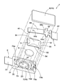
- the perspective view before an assembly showing the schematic structure of the breaker by one embodiment of the present invention Sectional drawing which shows the said breaker in a normal charge or discharge state. Sectional drawing which shows the said breaker at the time of an overcharge state or an abnormality.
- the top view of another modification of the said thermoresponsive element The top view of another modification of the above-mentioned thermal response element.
- the top view of another modification of the above-mentioned thermal response element The top view of another modification of the above-mentioned thermal response element.
- a breaker according to an embodiment of the present invention will be described with reference to the drawings.
- 1 to 3 show the configuration of the breaker 1.
- the breaker 1 is mounted on an electric device or the like and protects the electric device from an excessive temperature rise or an overcurrent.
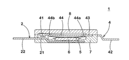
- the breaker 1 includes a fixed piece 2 having a fixed contact 21, a movable piece 4 having a movable contact 41 at its tip, a thermal responsive element 5 that deforms with a temperature change, and a PTC (Positive Temperature Coefficient) thermistor 6.
- the case 10 includes a case body (first case) 7, a lid member (second case) 8 mounted on the upper surface of the case body 7, and the like.
- the fixing piece 2 is formed, for example, by pressing a metal plate containing copper as a main component (other than this, a metal plate of copper-titanium alloy, nickel silver, brass, etc.), and is insert-molded into the case body 7. It is embedded.
- a terminal 22 that is electrically connected to an external circuit is formed at one end of the fixed piece 2, and a support portion 23 that supports the PTC thermistor 6 is formed at the other end side.
- the PTC thermistor 6 is mounted on convex protrusions (doughs) 24 formed at three locations on the support portion 23 of the fixed piece 2 and supported by the protrusions 24.
- the fixed contact 21 is formed at a position facing the movable contact 41 by clad, plating or coating of a material having good conductivity such as silver, nickel, nickel-silver alloy, copper-silver alloy, gold-silver alloy. It is exposed from a part of the opening 73a formed inside the case body 7.
- the terminal 22 is projected outward from the edge of the case body 7.
- the support portion 23 is exposed from an opening 73d formed inside the case body 7.
- the surface on the side where the fixed contact 21 is formed (that is, the upper surface in FIG. 1) is the A surface, and the opposite surface is the B surface. doing.
- the direction from the fixed contact 21 to the movable contact 41 is defined as the first direction and the direction opposite to the first direction is defined as the second direction
- the A surface faces the first direction
- the B surface faces the second direction.
- the movable piece 4 is formed into an arm shape symmetrical with respect to the center line in the longitudinal direction by pressing a plate-shaped metal material containing copper or the like as a main component.
- a movable contact 41 is formed at the tip of the movable piece 4 in the longitudinal direction.
- the movable contact 41 is formed of, for example, a material similar to that of the fixed contact 21, and is joined to the tip end of the movable piece 4 by a method such as welding, clad, crimping, or the like.
- a terminal 42 electrically connected to an external circuit is formed at the other end of the movable piece 4 in the longitudinal direction.
- the movable piece 4 has a contact portion 43 and an elastic portion 44 between the movable contact 41 and the terminal 42.
- the contact portion 43 contacts the case body 7 and the lid member 8 between the terminal 42 and the elastic portion 44.
- the contact portion 43 has a protruding portion 43a that protrudes like a wing in the lateral direction of the movable piece 4. Since the protrusion 43a is provided, the contact portion 43 is sandwiched between the case body 7 and the lid member 8 in a wide and large area, and the movable piece 4 is firmly fixed to the case 10.
- the elastic portion 44 extends from the contact portion 43 to the movable contact 41 side.
- the movable piece 4 is cantilevered by the case 10 at the abutment portion 43 on the proximal end side of the elastic portion 44, and is elastically deformed in this state to be formed at the tip portion of the elastic portion 44.
- the movable contact 41 that is present is pressed against the side of the fixed contact 21 and comes into contact with it, so that the fixed piece 2 and the movable piece 4 can be energized.
- the movable piece 4 is curved or bent in the elastic portion 44 by press working.
- a pair of protrusions 44 a and 44 b are formed on the lower surface of the elastic portion 44 so as to face the thermoresponsive element 5.
- the protrusion 44a protrudes toward the heat responsive element 5 at the base end side and contacts the heat responsive element 5 in a blocked state.
- the protrusion 44b protrudes toward the heat responsive element 5 on the tip side (that is, the movable contact 41 side) of the protrusion 44a, and contacts the heat responsive element 5 in a blocked state.
- the thermal responsive element 5 When the thermal responsive element 5 is deformed by overheating, the thermal responsive element 5 contacts the protrusions 44a and 44b, the deformation of the thermal responsive element 5 is transmitted to the elastic portion 44 via the protrusions 44a and 44b, and the movable piece 4 moves. The tip is pushed up (see Fig. 3).
- the heat responsive element 5 shifts the state of the movable piece 4 from a conductive state in which the movable contact 41 contacts the fixed contact 21 to a cutoff state in which the movable contact 41 is separated from the fixed contact 21.
- the heat responsive element 5 is formed in a plate shape by laminating thin plate materials having different thermal expansion coefficients, and has an initial shape in which a cross section is curved in an arc shape. When the reversing operation temperature is reached due to overheating, the curved shape of the heat responsive element 5 warps backward with snap motion, and is restored when the temperature falls below the normal return temperature due to cooling.
- the initial shape of the thermoresponsive element 5 can be formed by press working.
- thermoresponsive element 5 are not particularly limited as long as the elastic portion 44 of the movable piece 4 is pushed up by the reverse warp deformation of the thermoresponsive element 5 at the desired temperature and returned to its original state by the elastic force of the elastic portion 44.
- a rectangular shape is preferable from the viewpoint of productivity and efficiency of reverse warp deformation.
- thermoresponsive element 5 As the material of the heat-responsive element 5, two kinds of materials having different coefficients of thermal expansion, which are made of various alloys such as nickel silver, brass and stainless steel, are laminated and used in combination according to the required conditions.
- a material of the thermoresponsive element 5 that can obtain a stable reversal operation temperature and a normal reversion temperature it is desirable to combine a copper-nickel-manganese alloy on the high expansion side and an iron-nickel alloy on the low expansion side.
- a material in which an iron-nickel-chromium alloy is combined on the high expansion side and an iron-nickel alloy is combined on the low expansion side can be mentioned.
- there is a combination of an iron-nickel-chromium alloy on the high expansion side and an iron-nickel-cobalt alloy on the low expansion side there is a combination of an iron-nickel-chromium alloy on the high expansion side and an iron-nickel-cobalt alloy on the low expansion side.
- the PTC thermistor 6 electrically connects the fixed piece 2 and the movable piece 4 when the movable piece 4 is in the cutoff state.
- the PTC thermistor 6 is arranged between the fixed piece 2 and the thermoresponsive element 5. That is, the support portion 23 of the fixed piece 2 is located immediately below the thermoresponsive element 5 with the PTC thermistor 6 interposed therebetween.
- the type of the PTC thermistor 6 can be selected depending on the operating current, operating voltage, operating temperature, return temperature, etc.
- the material and shape are not particularly limited as long as these characteristics are not impaired.
- a ceramic sintered body containing barium titanate, strontium titanate or calcium titanate is used.
- so-called polymer PTC in which conductive particles such as carbon are contained in polymer may be used.
- the case body 7 and the lid member 8 constituting the case 10 are formed of a thermoplastic resin such as flame-retardant polyamide, polyphenylene sulfide (PPS) having excellent heat resistance, liquid crystal polymer (LCP), and polybutylene terephthalate (PBT). Has been done. A material other than the resin may be applied as long as the characteristics equal to or higher than those of the resin described above are obtained.
- a thermoplastic resin such as flame-retardant polyamide, polyphenylene sulfide (PPS) having excellent heat resistance, liquid crystal polymer (LCP), and polybutylene terephthalate (PBT).
- the case main body 7 is formed with a recess 73 which is an internal space for housing the movable piece 4, the thermoresponsive element 5, the PTC thermistor 6, and the like.
- the recess 73 has openings 73a and 73b for accommodating the movable piece 4, an opening 73c for accommodating the movable piece 4 and the thermoresponsive element 5, an opening 73d for accommodating the PTC thermistor 6, and the like. ing.
- the edges of the movable piece 4 and the heat responsive element 5 incorporated in the case body 7 are brought into contact with each other by the frame forming the recess 73, and are guided when the heat responsive element 5 is warped and deformed.
- the lid member 8 is configured to cover the recess 73.
- the lid member 8 may be configured to cover at least a part of the recess 73.
- a metal plate containing copper or the like as a main component or a metal plate such as stainless steel may be embedded in the lid member 8 by insert molding. The metal plate appropriately contacts the surface A of the movable piece 4 to restrict the movement of the movable piece 4, and contributes to the downsizing of the breaker 1 while enhancing the rigidity and strength of the lid member 8 and thus the case 10 as a housing. To do.
- the lid member 8 covers the case 73 so as to close the openings 73a, 73b, 73c and the like of the case body 7 that houses the fixed piece 2, the movable piece 4, the thermoresponsive element 5, the PTC thermistor 6 and the like. It is attached to the main body 7.
- the case body 7 and the lid member 8 are joined by ultrasonic welding, for example.
- FIG. 2 shows the operation of the breaker 1 in a normal charging or discharging state.
- the thermoresponsive element 5 maintains the initial shape before reverse warpage.
- the thermal responsive element 5 may be separated from the protrusions 44a and 44b of the movable piece 4 in the conductive state. As a result, the contact pressure between the movable contact 41 and the fixed contact 21 is increased, and the contact resistance between them is reduced.
- FIG. 3 shows the operation of the breaker 1 in the overcharged state or the abnormal state.
- the thermal responsive element 5 that has reached the reversing operation temperature is reversely warped and comes into contact with the elastic portion 44 of the movable piece 4, and the elastic portion 44 is pushed up and fixed contact 21 and movable contact. 41 is separated. At this time, the current flowing between the fixed contact 21 and the movable contact 41 is cut off.
- the thermoresponsive element 5 comes into contact with the movable piece 4, and a slight leakage current flows through the thermoresponsive element 5 and the PTC thermistor 6.
- the PTC thermistor 6 brings the fixed piece 2 and the movable piece 4 into conduction with each other via the thermal responsive element 5 that moves the movable piece 4 to the cutoff state.
- the PTC thermistor 6 continues to generate heat as long as such a leakage current flows, and dramatically increases the resistance value while maintaining the thermoresponsive element 5 in the reverse warped state, so that the current passes through the path between the fixed contact 21 and the movable contact 41. Does not flow through and there is only the above-mentioned slight leakage current (constituting a self-holding circuit). This leakage current can be used for other functions of the safety device.
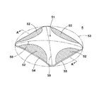
- FIG. 4 shows the thermoresponsive element 5.
- the thermoresponsive element 5 is formed in a curved plate shape.
- the thermoresponsive element 5 includes a first region 51 that deforms with a snap action due to a temperature change, and a second region 52 that inhibits the deformation of the first region 51.
- the deformation accompanied by the snap action is a deformation (hereinafter referred to as a snap deformation) which occurs instantaneously when the thermoresponsive element 5 reaches a specific temperature.
- the second area 52 is formed integrally with the first area 51.
- the second area 52 is formed continuously from the first area 51 in the hatched area in the drawing. Since the second region 52 is integrally and continuously formed from the first region 51, the first region 51 is integrally deformed with the second region 52. Therefore, during the snap deformation, the first region 51 and the second region 52 interfere with each other and the action of inhibiting the deformation of the first region 51 by the second region 52 is enhanced.
- thermoresponsive element 5 maintains the normal rotation shape shown in FIGS. 2 and 4 in a normal temperature range, and when it reaches the reversal operation temperature due to overheating, snap-deforms to the reversal shape shown in FIG. Along with this, the state of the movable piece 4 shifts from the conductive state to the cutoff state. After that, when the temperature of the heat responsive element 5 decreases to the normal rotation return temperature due to heat radiation or the like, the heat responsive element 5 snap-deforms into the normal rotation shape shown in FIGS. 2 and 4. Along with this, the state of the movable piece 4 returns from the cutoff state to the conductive state.
- the second region 52 acts so as to prevent the deformation of the first region 51 from the normal shape to the inverted shape and maintain the normal shape. As a result, the stress required to deform the thermoresponsive element 5 into the inverted shape is raised, and the reversal operation temperature of the thermoresponsive element 5 is easily increased.
- the second region 52 acts to prevent the first region 51 from deforming from the inverted shape to the normal shape and maintain the inverted shape.
- the above-mentioned stress required for the thermoresponsive element 5 to be deformed into the normal rotation shape is increased, and the normal rotation return temperature at which the thermoresponsive element 5 is snap-deformed into the normal rotation shape is lowered. Therefore, the normal rotation return temperature of the heat responsive element 5 can be easily lowered, and the difference between the reversal operation temperature and the normal rotation return temperature can be easily increased without making the radius of curvature of the heat responsive element 5 excessively small. It will be possible.
- the normal heat responsive element is restored to normal rotation. It is possible to significantly reduce the temperature. This makes it possible to easily lower the temperature at which the movable piece 4 returns from the cutoff state to the conductive state and delay the return of the movable piece 4 to the conductive state.
- the second region 52 is formed inside the circumscribing circle 53 of the first region 51. This makes it possible to increase the difference between the reversal operation temperature and the normal rotation recovery temperature without increasing the size of the heat responsive element 5.
- the thermoresponsive element 5 is formed in a rectangular shape in a plan view when viewed from the thickness direction.
- the first region 51 is formed on the two diagonal lines 59 of the thermoresponsive element 5.
- the thermal responsive element 5 as described above generates a large stress as the temperature changes. Therefore, the movable piece 4 having a large elastic force can be adopted, and the contact resistance between the fixed contact 21 and the movable contact 41 in the conductive state can be easily reduced.
- the heat responsive element 5 is formed in a rectangular shape having a long side 54 extending in the length direction and a short side 55 extending in the width direction perpendicular to the length direction in a plan view.
- the length of the diagonal line 59 is large, and a large stress is generated with a temperature change.
- the second region 52 is preferably formed along the long side 54. Furthermore, the second region 52 is preferably formed along the short side 55.
- the first region 51 is formed in an “X” shape in a plan view, and the second region 52 is formed around the first region 51. Such a second region 52 increases the effect of inhibiting the deformation of the first region 51, and increases the difference between the reversal operation temperature and the normal rotation return temperature.
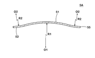
- FIG. 5 shows a cross section (cross section parallel to the long side 54) of the thermoresponsive element 5 in FIG.
- the radius of curvature R2 of the second region 52 is preferably larger than the radius of curvature R1 of the first region 51. According to such a configuration, it becomes possible to easily manufacture the thermoresponsive element 5 having the first region 51 and the second region 52. Further, the second region 52 as described above has a large effect of inhibiting the deformation of the first region 51.
- the radius of curvature R2 of the second region 52 may be infinite, that is, the second region 52 may be configured by a plane.
- FIG. 5 shows the relationship between the first region 51 and the second region 52 formed along the short side 55, but the second region formed along the first region 51 and the long side 54. The relationship with the region 52 is similar.
- FIG. 6 shows a cross section taken along line AA of a thermoresponsive element 5A which is a modified example of the thermoresponsive element 5.
- the thermal response element 5A differs from the thermal response element 5 in that the center O2 of curvature of the second region 52 is located on the opposite side of the center O1 of curvature of the first region 51 across the thermal response element 5. ing.
- the center of curvature O1 and the center of curvature O2 are transferred from the B surface side to the A surface side or from the A surface side to the B surface side of the thermoresponsive element 5 before and after the snap deformation.
- the thermoresponsive element 5A only the center of curvature O1 is transferred from the B surface side to the A surface side or from the A surface side to the B surface side of the thermoresponsive element 5A before and after the snap deformation. Therefore, since the deformation mode of the first region 51 and the deformation mode of the second region 52 are different, the effect of impeding the deformation of the first region 51 by the second region 52 is greatly obtained, and the reversal operation temperature and the normal rotation return temperature are obtained. It is possible to set the difference between and larger.
- the radius of curvature R2 of the second region 52 is preferably smaller than the radius of curvature R1 of the first region 51. Such a second region 52 has a large effect of inhibiting the deformation of the first region 51.
- the other configurations of the thermoresponsive element 5A are similar to those of the thermoresponsive element 5.
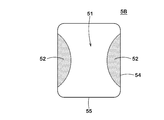
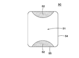
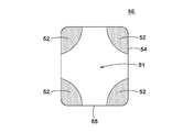
- thermoresponsive elements 5B to 5E which are other modified examples of the heat responsive element 5.
- the arrangement of the first region 51 and the second region 52 is different from that of the thermoresponsive element 5 and the like.
- the second region 52 is formed only along the long side 54. As shown in FIG. 8, in the thermoresponsive element 5C, the second region 52 is formed only along the short side 55.
- the first region 51 is formed in a “Y” shape, and the second region 52 is formed around the first region 51.
- the first region 51 is formed in a "+” shape, and the second region 52 is formed in the periphery thereof, that is, in the diagonal region of the thermoresponsive element 5E.
- the radius of curvature R1 of the first region 51, the center of curvature O1 and the radius of curvature R2 of the second region 52, and the center of curvature O2 can be set as shown in FIG. 5 or FIG.
- the first region 51 that snap-deforms with a change in temperature and the second region 52 that is integrally formed from the first region 51 and has a large effect of inhibiting the deformation of the first region 51 are easily formed. ..
- the first region 51 and the second region 52 are preferably arranged symmetrically with respect to the longitudinal centerline of the movable piece 4. With such a heat responsive element 5 and the like, the symmetry of the inverted shape after the snap deformation can be easily maintained.
- the breaker 1 of the present invention is not limited to the configuration of the above embodiment, and may be implemented in various modes. That is, the present invention is at least the heat-responsive element 5 formed in the shape of a curved plate, which is integrally formed from the first region 51 and the first region 51 which are deformed with a snap action according to a temperature change.
- the second region 52 may be formed inside the circumscribed circle 53 of the first region 51, including the second region 52 that inhibits the deformation of the first region 51.
- the method of joining the case body 7 and the lid member 8 is not limited to ultrasonic welding, and any method can be appropriately applied as long as the method can firmly join the two.
- a liquid or gel adhesive may be applied/filled and cured to bond the two.
- the case 10 is not limited to the form formed by the case body 7, the lid member 8 and the like, and may be formed by two or more parts.
- the present invention can also be applied to a mode in which a movable piece and a terminal piece are separately molded and electrically connected by welding or the like, for example, as disclosed in JP-A-2016-35822. ..
- the present invention can also be applied to a form in which the terminals 22 and 42 are exposed from the B surface of the case body 7.
- the present invention can be applied to a form in which the lid member 8 is omitted from the case 10, that is, a form in which the recess 73 of the case body 7 is opened and the movable piece 4 and the like are exposed.
- the distance between the fixed contact 21 and the movable contact 41 when the movable piece 4 is in the cutoff state can be easily increased.
- the terminal piece is insert-molded in the case body 7, and the movable piece 4 is welded to the terminal piece at the base end side thereof, as disclosed in JP-A-2016-35822. May be fixed by.
- the PTC thermistor 6 has a self-holding circuit, but it is also applicable to a form in which such a configuration is omitted.
- the movable piece 4 can be omitted while omitting the PTC thermistor 6. It is possible to substantially prevent the return from the cutoff state to the conduction state.
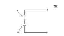
- FIG. 11 shows a secondary battery pack 500.
- the secondary battery pack 500 includes a secondary battery 501 and a breaker 1 provided in the output circuit of the secondary battery 501.
- FIG. 12 shows a safety circuit 502 for electrical equipment.
- the safety circuit 502 includes the breaker 1 in series in the output circuit of the secondary battery 501. According to the secondary battery pack 500 or the safety circuit 502 including the breaker 1, it is possible to manufacture the secondary battery pack 500 or the safety circuit 502 in which the difference between the operating temperature and the return temperature of the breaker 1 is large.
- Breaker 2 Fixed piece 4: Movable piece 5: Thermoresponsive element 21: Fixed contact 41: Moving contact 44: Elastic part 51: First area 52: Second area 53: Circumscribed circle 54: Long side 55: Short side 500: secondary battery pack 501: secondary battery 502: safety circuit O1: center of curvature O2: center of curvature R1: radius of curvature R2: radius of curvature
Landscapes
- Physics & Mathematics (AREA)
- Thermal Sciences (AREA)
- Thermally Actuated Switches (AREA)
Abstract
熱応動素子5は、湾曲する板状に形成される。熱応動素子5は、温度変化に伴いスナップアクションを伴い変形する第1領域51と、第1領域51から一体的に形成され、第1領域51の変形を阻害する第2領域52とを含む。第2領域52は、第1領域51の外接円の内側に形成されている。
Description
本発明は、小型のブレーカーに用いて好適な板状に形成された熱応動素子等に関するものである。
従来、各種電気機器の2次電池やモーター等の保護装置(安全回路)としてブレーカーが使用されている。
ブレーカーには、温度変化に応じて作動し、電流を導通又は遮断する熱応動素子が備えられている。特許文献1には、熱応動素子としてバイメタルを適用したブレーカーが示されている。バイメタルとは、熱膨張率の異なる2種類の板状の金属材料が積層されてなり、温度変化に応じて形状を変えること(熱変形)により、接点の導通状態を制御する素子である。同文献に示されたブレーカーは、固定片、可動片、熱応動素子、PTCサーミスター等の部品が、ケースに収納されてなり、固定片及び端子片の端子がケースから突出し、電気機器の電気回路に接続されて使用される。
ブレーカーは、充放電中の2次電池の温度が過度に上昇した場合、又は自動車、家電製品等の機器に装備されるモーター等に過電流が流れた場合等の異常が生じた際に、2次電池やモーター等を保護するために電流を遮断する。このような保護装置として用いられるブレーカーは、機器の安全を確保するために、温度変化に追従して正確に動作する(良好な温度特性を有する)ことと、通電時の抵抗値が安定していることが求められる。
また、ブレーカーが、ノート型パーソナルコンピュータ、タブレット型携帯情報端末機器又はスマートフォンと称される薄型の多機能携帯電話機等の電気機器に装備される2次電池等の保護装置として用いられる場合、上述した安全性の確保に加えて、小型化が要求される。特に、近年の携帯情報端末機器にあっては、ユーザーの小型化(薄型化)の志向が強く、各社から新規に発売される機器は、デザイン上の優位性を確保するために、小型に設計される傾向が顕著である。こうした背景の下、携帯情報端末機器を構成する一部品として、2次電池と共に実装されるブレーカーもまた、さらなる小型化が強く要求されている。
同文献の図3に示される通電状態において、熱応動素子は正転形状をとる。過充電等により熱応動素子の温度が上昇すると、スナップアクションにより、同文献の図4に示されるように熱応動素子が反転形状(逆反り形状)に変化し、可動片の先端近傍を押し上げる。これにより、固定片に設けられている固定接点と可動片に設けられている可動接点とが離隔し、ブレーカーは遮断状態となる。
その後、過充電状態等が解消されると、熱応動素子の温度が低下し、熱応動素子は正転形状に復帰し、可動片が導通状態に復帰する。可動片が導通状態から遮断状態に移行するための熱応動素子の反転動作温度及びブレーカーが遮断状態から導通状態に復帰するための熱応動素子の正転復帰温度は、ブレーカーが実装される機器の仕様等に応じて設定される。
機器の安全を考慮すると、2次電池等の温度が十分に低くなるまで遮断状態を維持できるように、正転復帰温度は低く設定されるのが望ましい。通常、熱応動素子の反転動作温度よりも正転復帰温度が低くなるように、熱応動素子は、可動片の側に凸となる湾曲した形状に形成されている。
正転復帰温度をより一層低く設定するには、熱応動素子の曲率半径を小さくすればよい。しかしながら、曲率半径の小さい熱応動素子は、その構造上、正転復帰温度にバラツキが生じ易く、特に小型化を追求したブレーカーにおいて、曲率半径の小さい熱応動素子を安定した品質で製造するのは困難を伴い、歩留まりが低下する一因となっている。従って、熱応動素子のサイズに対して曲率半径を過度に小さくすることなく、反転動作温度と正転復帰温度との差を大きくできる熱応動素子の開発が要望されている。
本発明は、上記課題を解決するためになされたものであり、曲率半径を過度に小さくすることなく、反転動作温度と正転復帰温度との差が大きい熱応動素子等を提供することを目的とする。
上記目的を達成するために、本発明は、湾曲する板状に形成された熱応動素子であって、温度変化に伴いスナップアクションを伴い変形する第1領域と、前記第1領域から一体的に形成され、前記第1領域の変形を阻害する第2領域とを含み、前記第2領域は、前記第1領域の外接円の内側に形成されている。
本発明に係る前記熱応動素子において、厚さ方向から視た平面視で、矩形状に形成され、前記第1領域は、2つの対角線上に形成されている、ことが望ましい。
本発明に係る前記熱応動素子において、厚さ方向から視た平面視で、長さ方向にのびる長辺と、前記長さ方向に垂直な幅方向にのびる短辺とを有する長方形状に形成され、前記第2領域は、前記長辺に沿って形成されている、ことが望ましい。
本発明に係る前記熱応動素子において、厚さ方向から視た平面視で、長さ方向にのびる長辺と、前記長さ方向に垂直な幅方向にのびる短辺とを有する長方形状に形成され、前記第2領域は、前記短辺に沿って形成されている、ことが望ましい。
本発明に係る前記熱応動素子において、前記第2領域の曲率半径は、前記第1領域の曲率半径よりも大きい、ことが望ましい。
本発明に係る前記熱応動素子において、前記第2領域の曲率中心は、熱応動素子を挟んで前記第1領域の曲率中心とは反対側に位置している、ことが望ましい。
また、本発明のブレーカーは、前記熱応動素子と、固定接点と、弾性変形する弾性部及び該弾性部の先端部に可動接点を有し、前記可動接点を前記固定接点に押圧して接触させる可動片とを備えたブレーカーであって、前記熱応動素子は、温度変化に伴って変形することにより、前記可動片の状態を前記可動接点が前記固定接点に接触する導通状態から前記可動接点が前記固定接点から離隔する遮断状態に移行可能である、ことを特徴とする。
本発明の電気機器用の安全回路は、前記ブレーカーを備えた、ことを特徴とする。
本発明の電気機器用の2次電池パックは、前記ブレーカーを備えた、ことを特徴とする。
本発明の熱応動素子によれば、温度変化に伴いスナップアクションを伴い変形する第1領域と、第1領域から一体的に形成され、第1領域の変形を阻害する第2領域とを含んでいる。第1領域は、熱応動素子の温度上昇に伴い、正転形状から反転形状に変形するための応力を発生する。このとき第2領域は第1領域の正転形状から反転形状への変形を阻害して正転形状を維持するように作用する。その結果、熱応動素子が反転形状に変形するために必要とされる上記応力が引き上げられ、熱応動素子の反転動作温度が容易に高められる。
一方、その後、熱応動素子の温度が下降する際には、第2領域は第1領域の反転形状から正転形状への変形を阻害して反転形状を維持するように作用する。その結果、熱応動素子が正転形状に変形するために必要とされる上記応力が引き上げられ、熱応動素子が正転形状にスナップ変形する正転復帰温度が低められる。従って、熱応動素子の正転復帰温度が容易に低められ、熱応動素子の曲率半径を過度に小さくすることなく、反転動作温度と正転復帰温度との差を容易に大きくすることが可能となる。
また、第2領域は、第1領域の外接円の内側に形成されている。これにより、熱応動素子のサイズを肥大させることなく、反転動作温度と正転復帰温度との差を大きくすることが可能となる。
本発明の一実施形態によるブレーカーについて図面を参照して説明する。図1乃至図3は、ブレーカー1の構成を示している。ブレーカー1は、電気機器等に実装され、過度な温度上昇又は過電流から電気機器を保護する。
ブレーカー1は、固定接点21を有する固定片2と、先端部に可動接点41を有する可動片4と、温度変化に伴って変形する熱応動素子5と、PTC(Positive Temperature Coefficient)サーミスター6と、固定片2、可動片4、熱応動素子5及びPTCサーミスター6を収容するケース10等によって構成されている。ケース10は、ケース本体(第1ケース)7とケース本体7の上面に装着される蓋部材(第2ケース)8等によって構成されている。
固定片2は、例えば、銅等を主成分とする金属板(この他、銅-チタニウム合金、洋白、黄銅などの金属板)をプレス加工することにより形成され、ケース本体7にインサート成形により埋め込まれている。固定片2の一端には外部回路と電気的に接続される端子22が形成され、他端側には、PTCサーミスター6を支持する支持部23が形成されている。PTCサーミスター6は、固定片2の支持部23に3箇所形成された凸状の突起(ダボ)24の上に載置されて、突起24に支持される。固定片2が階段状に曲げられることにより、固定接点21と支持部23とが段違いに配置され、PTCサーミスター6を収納する空間が容易に確保される。
固定接点21は、銀、ニッケル、ニッケル-銀合金の他、銅-銀合金、金-銀合金などの導電性の良い材料のクラッド、メッキ又は塗布等により可動接点41に対向する位置に形成され、ケース本体7の内部に形成されている開口73aの一部から露出されている。端子22はケース本体7の端縁から外側に突き出されている。支持部23は、ケース本体7の内部に形成されている開口73dから露出されている。
本出願においては、特に断りのない限り、固定片2において、固定接点21が形成されている側の面(すなわち図1において上側の面)をA面、その反対側の面をB面として説明している。固定接点21から可動接点41に向く方向を第1方向と、第1方向とは反対の方向を第2方向とそれぞれ定義した場合、A面は第1方向を向き、B面は第2方向を向く。他の部品、例えば、可動片4及び熱応動素子5、PTCサーミスター6等についても同様である。
可動片4は、銅等を主成分とする板状の金属材料をプレス加工することにより、長手方向の中心線に対して対称なアーム状に形成されている。
可動片4の長手方向の先端部には、可動接点41が形成されている。可動接点41は、例えば、固定接点21と同等の材料によって形成され、溶接の他、クラッド、かしめ(crimping)等の手法によって可動片4の先端部に接合されている。
可動片4の長手方向の他端部には、外部回路と電気的に接続される端子42が形成されている。可動片4は、可動接点41と端子42の間に、当接部43及び弾性部44を有している。当接部43は、端子42と弾性部44との間でケース本体7及び蓋部材8と当接する。当接部43は、可動片4の短手方向に翼状に突出する突出部43aを有する。突出部43aが設けられていることにより、当接部43が幅広く大きな領域でケース本体7及び蓋部材8によって挟み込まれ、可動片4がケース10に対して強固に固定される。
弾性部44は、当接部43から可動接点41の側に延出されている。可動片4は、弾性部44の基端側の当接部43で、ケース10によって片持ち支持され、その状態で弾性部44が弾性変形することにより、弾性部44の先端部に形成されている可動接点41が固定接点21の側に押圧されて接触し、固定片2と可動片4とが通電可能となる。
可動片4は、弾性部44において、プレス加工により湾曲又は屈曲されている。また、弾性部44の下面には、熱応動素子5に対向して一対の突起44a,44bが形成されている。突起44aは、基端側で熱応動素子5に向って突出し、遮断状態で熱応動素子5と当接する。突起44bは、突起44aよりも先端側(すなわち可動接点41側)で熱応動素子5に向って突出し、遮断状態で熱応動素子5と当接する。過熱により熱応動素子5が変形すると、熱応動素子5が突起44a及び突起44bと当接し、熱応動素子5の変形が突起44a及び突起44bを介して弾性部44に伝達され、可動片4の先端部が押し上げられる(図3参照)。
熱応動素子5は、可動片4の状態を可動接点41が固定接点21に接触する導通状態から可動接点41が固定接点21から離隔する遮断状態に移行させる。熱応動素子5は、熱膨張率の異なる薄板材を積層することにより板状に形成され、断面が円弧状に湾曲した初期形状をなしている。過熱により反転動作温度に達すると、熱応動素子5の湾曲形状は、スナップモーションを伴って逆反りし、冷却により正転復帰温度を下回ると復元する。熱応動素子5の初期形状は、プレス加工により形成することができる。所期の温度で熱応動素子5の逆反り変形により可動片4の弾性部44が押し上げられ、かつ弾性部44の弾性力により元に戻る限り、熱応動素子5の材質及び形状は特に限定されるものでないが、生産性及び逆反り変形の効率性の観点から矩形状が望ましい。
熱応動素子5の材料としては、洋白、黄銅、ステンレス鋼等の各種の合金からなる熱膨張率の異なる2種類の材料を積層したものが、所要条件に応じて組み合わせて使用される。例えば、安定した反転動作温度及び正転復帰温度が得られる熱応動素子5の材料としては、高膨脹側に銅-ニッケル-マンガン合金、低膨脹側に鉄-ニッケル合金を組み合わせたものが望ましい。また、化学的安定性の観点からさらに望ましい材料として、高膨脹側に鉄-ニッケル-クロム合金、低膨脹側に鉄-ニッケル合金を組み合わせたものが挙げられる。さらにまた、化学的安定性及び加工性の観点からさらに望ましい材料として、高膨脹側に鉄-ニッケル-クロム合金、低膨脹側に鉄-ニッケル-コバルト合金を組み合わせたものが挙げられる。
PTCサーミスター6は、可動片4が遮断状態にあるとき、固定片2と可動片4とを導通させる。PTCサーミスター6は、固定片2と熱応動素子5との間に配設されている。すなわち、PTCサーミスター6を挟んで、固定片2の支持部23は熱応動素子5の直下に位置している。熱応動素子5の逆反り変形により固定片2と可動片4との通電が遮断されたとき、PTCサーミスター6に流れる電流が増大する。PTCサーミスター6は、温度上昇と共に抵抗値が増大して電流を制限する正特性サーミスターであれば、作動電流、作動電圧、作動温度、復帰温度などの必要に応じて種類を選択でき、その材料及び形状はこれらの諸特性を損なわない限り特に限定されるものではない。本実施形態では、チタニウム酸バリウム、チタニウム酸ストロンチウム又はチタニウム酸カルシウムを含むセラミック焼結体が用いられる。セラミック焼結体の他、ポリマーにカーボン等の導電性粒子を含有させたいわゆるポリマーPTCを用いてもよい。
ケース10を構成するケース本体7及び蓋部材8は、難燃性のポリアミド、耐熱性に優れたポリフェニレンサルファイド(PPS)、液晶ポリマー(LCP)、ポリブチレンテレフタレート(PBT)などの熱可塑性樹脂により成形されている。上述した樹脂と同等以上の特性が得られるのであれば、樹脂以外の材料を適用してもよい。
ケース本体7には、可動片4、熱応動素子5及びPTCサーミスター6などを収容するための内部空間である凹部73が形成されている。凹部73は、可動片4を収容するための開口73a,73b、可動片4及び熱応動素子5を収容するための開口73c、並びに、PTCサーミスター6を収容するための開口73d等を有している。なお、ケース本体7に組み込まれた可動片4、熱応動素子5の端縁は、凹部73を構成する枠によってそれぞれ当接され、熱応動素子5の逆反り変形時に案内される。
蓋部材8は、凹部73を覆うように構成されている。蓋部材8は、凹部73の少なくとも一部を覆う形態であってもよい。蓋部材8には、銅等を主成分とする金属板又はステンレス鋼等の金属板がインサート成形によって埋め込まれていてもよい。金属板は、可動片4のA面と適宜当接し、可動片4の動きを規制すると共に、蓋部材8のひいては筐体としてのケース10の剛性・強度を高めつつブレーカー1の小型化に貢献する。
図1が示すように、固定片2、可動片4、熱応動素子5及びPTCサーミスター6等を収容したケース本体7の開口73a、73b、73c等を塞ぐように、蓋部材8が、ケース本体7に装着される。ケース本体7と蓋部材8とは、例えば超音波溶着によって接合される。
図2及び図3は、ブレーカー1の動作の概略を示している。図2は、通常の充電又は放電状態におけるブレーカー1の動作を示している。通常の充電又は放電状態においては、熱応動素子5は逆反り前の初期形状を維持している。弾性部44によって可動接点41が固定接点21の側に押圧されることにより、可動接点41と固定接点21とが接触し、ブレーカー1の固定片2と可動片4とが導通可能な状態とされる。
図2に示されるように、熱応動素子5は、導通状態の可動片4の突起44a及び突起44bと離隔していてもよい。これにより、可動接点41と固定接点21との接触圧力が高められ、両者間の接触抵抗が低減される。
図3は、過充電状態又は異常時などにおけるブレーカー1の動作を示している。過充電又は異常により高温状態となると、反転動作温度に達した熱応動素子5は逆反り変形して可動片4の弾性部44と接触し、弾性部44が押し上げられて固定接点21と可動接点41とが離隔する。このとき、固定接点21と可動接点41の間を流れていた電流は遮断される。一方、熱応動素子5は、可動片4と接触して、僅かな漏れ電流が熱応動素子5及びPTCサーミスター6を通して流れることとなる。すなわち、PTCサーミスター6は、可動片4を遮断状態に移行させている熱応動素子5を介して、固定片2と可動片4とを導通させる。PTCサーミスター6は、このような漏れ電流の流れる限り発熱を続け、熱応動素子5を逆反り状態に維持させつつ抵抗値を激増させるので、電流は固定接点21と可動接点41の間の経路を流れず、上述の僅かな漏れ電流のみが存在する(自己保持回路を構成する)。この漏れ電流は安全装置の他の機能に充てることができる。
過充電状態を解除し、又は異常状態を解消すると、PTCサーミスター6の発熱も収まり、熱応動素子5は正転復帰温度に戻り、元の初期形状に復元する。そして、可動片4の弾性部44の弾性力によって可動接点41と固定接点21とは再び接触し、回路は遮断状態を解かれ、図2に示す導通状態に復帰する。
図4は、熱応動素子5を示している。熱応動素子5は、湾曲する板状に形成されている。熱応動素子5は、温度変化に伴いスナップアクションを伴い変形する第1領域51と、第1領域51の変形を阻害する第2領域52とを含んでいる。スナップアクションを伴う変形とは、熱応動素子5が特定の温度に達したとき、瞬間的に生ずる変形(以下、スナップ変形と記す)である。
第2領域52は、第1領域51から一体的に形成されている。第2領域52は、図中ハッチングされた領域において、第1領域51から連続して形成されている。第2領域52が第1領域51から一体的に連続して形成されていることにより、第1領域51は第2領域52と一体的に変形する。従って、上記スナップ変形の際に第1領域51と第2領域52とが互いに干渉し、第2領域52による第1領域51の変形を阻害する作用が高められる。
熱応動素子5は、通常の温度領域では、図2及び図4に示される正転形状を維持し、過熱により反転動作温度に達すると、図3に示される反転形状にスナップ変形する。これに伴い、可動片4の状態が導通状態から遮断状態に移行する。その後、放熱等によって熱応動素子5の温度が正転復帰温度まで低下すると、熱応動素子5は、図2及び図4に示される正転形状にスナップ変形する。これに伴い、可動片4の状態が遮断状態から導通状態に復帰する。
第1領域51は、熱応動素子5の温度上昇に伴い、熱応動素子5が正転形状から反転形状にスナップ変形するための応力を発生する。このとき第2領域52は第1領域51の正転形状から反転形状への変形を阻害して正転形状を維持するように作用する。その結果、熱応動素子5が反転形状に変形するために必要とされる上記応力が引き上げられ、熱応動素子5の反転動作温度が容易に高められる。
一方、その後、熱応動素子5の温度が下降する際には、第2領域52は第1領域51の反転形状から正転形状への変形を阻害し、反転形状を維持するように作用する。その結果、熱応動素子5が正転形状に変形するために必要とされる上記応力が引き上げられ、熱応動素子5が正転形状にスナップ変形する正転復帰温度が低められる。従って、熱応動素子5の正転復帰温度が容易に低められ、熱応動素子5の曲率半径を過度に小さくすることなく、反転動作温度と正転復帰温度との差を容易に大きくすることが可能となる。
また、例えば、熱応動素子5を構成する材料及び寸法等を変更し、反転動作温度を従来の熱応動素子と同等となるように調整することにより、従来の熱応動素子に対して正転復帰温度を大幅に低下させることが可能となる。これにより、可動片4の状態が遮断状態から導通状態に復帰する温度を引き下げて、可動片4の導通状態への復帰を遅延させることが容易に可能となる。
また、第2領域52は、第1領域51の外接円53の内側に形成されている。これにより、熱応動素子5のサイズを肥大させることなく、反転動作温度と正転復帰温度との差を大きくすることが可能となる。
熱応動素子5は、その厚さ方向から視た平面視で、矩形状に形成されている。そして、第1領域51は、熱応動素子5の2つの対角線59上に形成されている。このような熱応動素子5は、温度変化に伴い大きな応力を発生する。従って、弾性力の大きい可動片4を採用し、導通状態における固定接点21と可動接点41との接触抵抗を、容易に低下させることが可能となる。
熱応動素子5は、その平面視で、長さ方向にのびる長辺54と、長さ方向に垂直な幅方向にのびる短辺55とを有する長方形状に形成されている。このような熱応動素子5は、対角線59の長さが大きく、温度変化に伴い大きな応力を発生する。
そして、第2領域52は、長辺54に沿って形成されているのが望ましい。さらに、第2領域52は、短辺55に沿って形成されているのが望ましい。本実施形態の熱応動素子5では、平面視で、第1領域51が”X”字状に形成され、その周辺に第2領域52が形成されている。このような第2領域52によって、第1領域51の変形を阻害する作用が大きくなり、反転動作温度と正転復帰温度との差が大きくなる。
図5は、図4における熱応動素子5のA-A線断面(長辺54に平行な断面)を示している。第2領域52の曲率半径R2は、第1領域51の曲率半径R1よりも大きいのが望ましい。このような構成によれば、第1領域51及び第2領域52を有する熱応動素子5を容易に製造することが可能となる。また、このような第2領域52は、第1領域51の変形を阻害する作用が大きい。なお、第2領域52の曲率半径R2が無限大、すなわち、第2領域52は平面にて構成されていてもよい。また、図5では、第1領域51と短辺55に沿って形成された第2領域52との関係が示されているが、第1領域51と長辺54に沿って形成された第2領域52との関係も同様である。
図6は、熱応動素子5の変形例である熱応動素子5AのA-A線断面を示している。熱応動素子5Aは、第2領域52の曲率中心O2が、熱応動素子5を挟んで第1領域51の曲率中心O1とは反対側に位置している点で、熱応動素子5とは異なっている。
熱応動素子5では、スナップ変形の前後で曲率中心O1及び曲率中心O2が、熱応動素子5のB面側からA面側、又はA面側からB面側に移転する。これに対して、熱応動素子5Aでは、スナップ変形の前後で曲率中心O1のみが熱応動素子5AのB面側からA面側、又はA面側からB面側に移転する。従って、第1領域51の変形モードと第2領域52の変形モードとが異なるため、第2領域52による第1領域51の変形を阻害する作用が大きく得られ、反転動作温度と正転復帰温度との差をより一層大きく設定することが可能となる。
熱応動素子5Aにあっては、第2領域52の曲率半径R2は、第1領域51の曲率半径R1よりも小さいのが望ましい。このような第2領域52は、第1領域51の変形を阻害する作用が大きい。熱応動素子5Aのその他の構成は、熱応動素子5と同様である。
図7乃至図10は、熱応動素子5の別の変形例である熱応動素子5B乃至5Eを示している。熱応動素子5B乃至5Eでは、上記熱応動素子5等に対して、第1領域51及び第2領域52の配置が異なっている。
図7に示されるように、熱応動素子5Bでは、第2領域52は、長辺54のみに沿って形成されている。図8に示されるように、熱応動素子5Cでは、第2領域52は、短辺55のみに沿って形成されている。
図9に示されるように、熱応動素子5Dでは、第1領域51が”Y”字状に形成され、その周辺に第2領域52が形成されている。図10に示されるように、熱応動素子5Eでは、第1領域51が”+”字状に形成され、その周辺すなわち熱応動素子5Eの対角領域に第2領域52が形成されている。
熱応動素子5B乃至5Eのいずれにおいても、第1領域51の曲率半径R1、曲率中心O1及び第2領域52の曲率半径R2、曲率中心O2を図5又は図6のごとく設定することができる。これにより、温度変化に伴いスナップ変形する第1領域51と、第1領域51から一体的に形成され、第1領域51の変形を阻害する作用の大きい第2領域52とが容易に形成される。
なお、熱応動素子5、5A乃至5Eのいずれにおいても、第1領域51及び第2領域52は、可動片4の長手方向の中心線に対して対称に配されているのが望ましい。このような熱応動素子5等により、スナップ変形後の反転形状の対称性も容易に維持される。
本発明のブレーカー1は、上記実施形態の構成に限られることなく、種々の態様に変更して実施されうる。すなわち、本発明は、少なくとも、湾曲する板状に形成された熱応動素子5であって、温度変化に伴いスナップアクションを伴い変形する第1領域51と、第1領域51から一体的に形成され、第1領域51の変形を阻害する第2領域52とを含み、第2領域52は、第1領域51の外接円53の内側に形成されていればよい。
例えば、ケース本体7と蓋部材8との接合手法は、超音波溶着に限られることなく、両者が強固に接合される手法であれば、適宜適用することができる。例えば、液状又はゲル状の接着剤を塗布・充填し、硬化させることにより、両者が接着されてもよい。また、ケース10は、ケース本体7と蓋部材8等によって構成される形態に限られることなく、2個以上の部品によって構成されていればよい。
また、本発明は、例えば、特開2016-35822号公報に示されるような、可動片と端子片とが別々に成形され、溶接等によって電気的に接続される形態にも適用することができる。また、本発明は、端子22及び42がケース本体7のB面から露出している形態にも適用することができる。
さらにまた、本発明は、ケース10から蓋部材8が省かれる形態、すなわち、ケース本体7の凹部73が開放され、可動片4等が露出する形態にも適用可能である。このような形態では、可動片4が遮断状態にあるときの固定接点21と可動接点41との距離が容易に拡大されうる。なお、かかる形態では、上記特開2016-35822号公報に示されように、端子片は、ケース本体7にインサート成形され、可動片4は、その基端側で端子片に溶接等されることにより、固定されていてもよい。
本実施形態では、PTCサーミスター6による自己保持回路を有しているが、このような構成を省いた形態であっても適用可能である。例えば、本発明の熱応動素子5等で正転復帰温度を通常の使用状態での熱応動素子の温度領域よりも十分に低く設定することにより、PTCサーミスター6を省きながらも、可動片4の遮断状態から導通状態への復帰を実質的に阻止できる。
また、本発明のブレーカー1は、2次電池パック、電気機器用の安全回路等にも広く適用できる。図11は2次電池パック500を示す。2次電池パック500は、2次電池501と、2次電池501の出力回路中に設けたブレーカー1とを備える。図12は電気機器用の安全回路502を示す。安全回路502は2次電池501の出力回路中に直列にブレーカー1を備えている。ブレーカー1を備えた2次電池パック500又は安全回路502によれば、ブレーカー1の動作温度と復帰温度との差が大きい2次電池パック500又は安全回路502を製造できる。
1 :ブレーカー
2 :固定片
4 :可動片
5 :熱応動素子
21 :固定接点
41 :可動接点
44 :弾性部
51 :第1領域
52 :第2領域
53 :外接円
54 :長辺
55 :短辺
500 :2次電池パック
501 :2次電池
502 :安全回路
O1 :曲率中心
O2 :曲率中心
R1 :曲率半径
R2 :曲率半径
2 :固定片
4 :可動片
5 :熱応動素子
21 :固定接点
41 :可動接点
44 :弾性部
51 :第1領域
52 :第2領域
53 :外接円
54 :長辺
55 :短辺
500 :2次電池パック
501 :2次電池
502 :安全回路
O1 :曲率中心
O2 :曲率中心
R1 :曲率半径
R2 :曲率半径
Claims (9)
- 湾曲する板状に形成された熱応動素子であって、
温度変化に伴いスナップアクションを伴い変形する第1領域と、
前記第1領域から一体的に形成され、前記第1領域の変形を阻害する第2領域とを含み、
前記第2領域は、前記第1領域の外接円の内側に形成されている、
ことを特徴とする熱応動素子。 - 厚さ方向から視た平面視で、矩形状に形成され、
前記第1領域は、2つの対角線上に形成されている、請求項1記載の熱応動素子。 - 厚さ方向から視た平面視で、長さ方向にのびる長辺と、前記長さ方向に垂直な幅方向にのびる短辺とを有する長方形状に形成され、
前記第2領域は、前記長辺に沿って形成されている、請求項1又は2に記載の熱応動素子。 - 厚さ方向から視た平面視で、長さ方向にのびる長辺と、前記長さ方向に垂直な幅方向にのびる短辺とを有する長方形状に形成され、
前記第2領域は、前記短辺に沿って形成されている、請求項1又は2に記載の熱応動素子。 - 前記第2領域の曲率半径は、前記第1領域の曲率半径よりも大きい、請求項1乃至4のいずれかに記載の熱応動素子。
- 前記第2領域の曲率中心は、熱応動素子を挟んで前記第1領域の曲率中心とは反対側に位置している、請求項1乃至4のいずれかに記載の熱応動素子。
- 請求項1乃至6のいずれかに記載の熱応動素子と、
固定接点と、
弾性変形する弾性部及び該弾性部の先端部に可動接点を有し、前記可動接点を前記固定接点に押圧して接触させる可動片とを備えたブレーカーであって、
前記熱応動素子は、温度変化に伴って変形することにより、前記可動片の状態を前記可動接点が前記固定接点に接触する導通状態から前記可動接点が前記固定接点から離隔する遮断状態に移行可能である、
ことを特徴とするブレーカー。 - 請求項1乃至7のいずれかに記載のブレーカーを備えた、ことを特徴とする電気機器用の安全回路。
- 請求項1乃至7のいずれかに記載のブレーカーを備えた、ことを特徴とする2次電池パック。
Priority Applications (1)
| Application Number | Priority Date | Filing Date | Title |
|---|---|---|---|
| CN201980077924.2A CN113168991B (zh) | 2018-12-14 | 2019-12-03 | 热响应元件、断路器、安全电路及二次电池组 |
Applications Claiming Priority (2)
| Application Number | Priority Date | Filing Date | Title |
|---|---|---|---|
| JP2018233952A JP7083742B2 (ja) | 2018-12-14 | 2018-12-14 | 熱応動素子、ブレーカー、安全回路及び2次電池パック |
| JP2018-233952 | 2018-12-14 |
Publications (1)
| Publication Number | Publication Date |
|---|---|
| WO2020121896A1 true WO2020121896A1 (ja) | 2020-06-18 |
Family
ID=71075311
Family Applications (1)
| Application Number | Title | Priority Date | Filing Date |
|---|---|---|---|
| PCT/JP2019/047242 Ceased WO2020121896A1 (ja) | 2018-12-14 | 2019-12-03 | 熱応動素子、ブレーカー、安全回路及び2次電池パック |
Country Status (3)
| Country | Link |
|---|---|
| JP (1) | JP7083742B2 (ja) |
| CN (1) | CN113168991B (ja) |
| WO (1) | WO2020121896A1 (ja) |
Cited By (1)
| Publication number | Priority date | Publication date | Assignee | Title |
|---|---|---|---|---|
| CN117678023A (zh) * | 2021-07-21 | 2024-03-08 | 打矢恒温器株式会社 | 热响应元件及其制造方法 |
Citations (4)
| Publication number | Priority date | Publication date | Assignee | Title |
|---|---|---|---|---|
| JPS5028668A (ja) * | 1973-07-18 | 1975-03-24 | ||
| JPH02134636U (ja) * | 1989-04-13 | 1990-11-08 | ||
| US20020044624A1 (en) * | 2000-10-13 | 2002-04-18 | Davis George D. | Laser adjusted set-point of bimetallic thermal disc |
| JP2017010621A (ja) * | 2015-06-16 | 2017-01-12 | ボーンズ株式会社 | 熱応動素子並びにそれを備えたブレーカー、安全回路、及び、二次電池パック |
Family Cites Families (4)
| Publication number | Priority date | Publication date | Assignee | Title |
|---|---|---|---|---|
| JP2827079B2 (ja) * | 1994-02-01 | 1998-11-18 | 株式会社生方製作所 | サーマルプロテクタ |
| US7298239B2 (en) * | 2002-05-07 | 2007-11-20 | Ubukata Industries Co., Ltd. | Thermal protector |
| US9460876B2 (en) * | 2011-12-22 | 2016-10-04 | Komatsulite Mfg. Co., Ltd. | Breaker, and safety circuit and secondary battery circuit provided with the same |
| JP6216152B2 (ja) * | 2013-05-13 | 2017-10-18 | ボーンズ株式会社 | ブレーカー及びそれを備えた安全回路並びに2次電池回路 |
-
2018
- 2018-12-14 JP JP2018233952A patent/JP7083742B2/ja active Active
-
2019
- 2019-12-03 CN CN201980077924.2A patent/CN113168991B/zh active Active
- 2019-12-03 WO PCT/JP2019/047242 patent/WO2020121896A1/ja not_active Ceased
Patent Citations (4)
| Publication number | Priority date | Publication date | Assignee | Title |
|---|---|---|---|---|
| JPS5028668A (ja) * | 1973-07-18 | 1975-03-24 | ||
| JPH02134636U (ja) * | 1989-04-13 | 1990-11-08 | ||
| US20020044624A1 (en) * | 2000-10-13 | 2002-04-18 | Davis George D. | Laser adjusted set-point of bimetallic thermal disc |
| JP2017010621A (ja) * | 2015-06-16 | 2017-01-12 | ボーンズ株式会社 | 熱応動素子並びにそれを備えたブレーカー、安全回路、及び、二次電池パック |
Cited By (2)
| Publication number | Priority date | Publication date | Assignee | Title |
|---|---|---|---|---|
| CN117678023A (zh) * | 2021-07-21 | 2024-03-08 | 打矢恒温器株式会社 | 热响应元件及其制造方法 |
| CN117678023B (zh) * | 2021-07-21 | 2026-04-03 | 打矢恒温器株式会社 | 热响应元件及其制造方法 |
Also Published As
| Publication number | Publication date |
|---|---|
| JP7083742B2 (ja) | 2022-06-13 |
| CN113168991A (zh) | 2021-07-23 |
| JP2020095888A (ja) | 2020-06-18 |
| CN113168991B (zh) | 2024-10-11 |
Similar Documents
| Publication | Publication Date | Title |
|---|---|---|
| JP7064350B2 (ja) | ブレーカー及びそれを備えた安全回路 | |
| US11329325B2 (en) | Breaker and safety circuit provided with same | |
| JP6997689B2 (ja) | ブレーカー、安全回路及び2次電池パック | |
| CN111418038B (zh) | 断路器及具备该断路器的安全电路 | |
| JP6979127B2 (ja) | ブレーカー、安全回路及び2次電池パック | |
| JP6967932B2 (ja) | ブレーカー及びそれを備えた安全回路。 | |
| WO2020022298A1 (ja) | ブレーカー、安全回路及び2次電池パック | |
| JP6457810B2 (ja) | ブレーカー及びそれを備えた安全回路並びに2次電池回路。 | |
| JP6204721B2 (ja) | ブレーカー及びそれを備えた安全回路並びに2次電池回路 | |
| WO2020121896A1 (ja) | 熱応動素子、ブレーカー、安全回路及び2次電池パック | |
| CN115053314B (zh) | 断路器、安全电路以及二次电池组 | |
| JP6997687B2 (ja) | ブレーカー及び安全回路 | |
| WO2020095694A1 (ja) | 熱応動素子、ブレーカー、安全回路及び2次電池パック | |
| JP7425768B2 (ja) | ブレーカー、安全回路及び2次電池パック | |
| JP7425710B2 (ja) | ブレーカー及びそれを備えた安全回路、2次電池パック | |
| JP6831186B2 (ja) | ブレーカー及びそれを備えた安全回路並びに2次電池回路。 | |
| JP2019008920A (ja) | 電流遮断装置及びそれを備えた2次電池パック。 | |
| JP2018060746A (ja) | ブレーカー並びにそれを備えた安全回路及び2次電池パック。 | |
| WO2020084739A1 (ja) | 2次電池回路及びその製造方法 | |
| WO2023119887A1 (ja) | ブレーカー、安全回路及び2次電池パック | |
| WO2020084740A1 (ja) | ブレーカー | |
| JP2019075354A (ja) | 電流遮断装置、安全回路及び2次電池パック。 |
Legal Events
| Date | Code | Title | Description |
|---|---|---|---|
| 121 | Ep: the epo has been informed by wipo that ep was designated in this application |
Ref document number: 19896925 Country of ref document: EP Kind code of ref document: A1 |
|
| NENP | Non-entry into the national phase |
Ref country code: DE |
|
| 122 | Ep: pct application non-entry in european phase |
Ref document number: 19896925 Country of ref document: EP Kind code of ref document: A1 |