WO2020121973A1 - 物体識別システム、演算処理装置、自動車、車両用灯具、分類器の学習方法 - Google Patents
物体識別システム、演算処理装置、自動車、車両用灯具、分類器の学習方法 Download PDFInfo
- Publication number
- WO2020121973A1 WO2020121973A1 PCT/JP2019/047876 JP2019047876W WO2020121973A1 WO 2020121973 A1 WO2020121973 A1 WO 2020121973A1 JP 2019047876 W JP2019047876 W JP 2019047876W WO 2020121973 A1 WO2020121973 A1 WO 2020121973A1
- Authority
- WO
- WIPO (PCT)
- Prior art keywords
- range
- image
- identification system
- images
- object identification
- Prior art date
- Legal status (The legal status is an assumption and is not a legal conclusion. Google has not performed a legal analysis and makes no representation as to the accuracy of the status listed.)
- Ceased
Links
Images
















Classifications
-
- G—PHYSICS
- G01—MEASURING; TESTING
- G01S—RADIO DIRECTION-FINDING; RADIO NAVIGATION; DETERMINING DISTANCE OR VELOCITY BY USE OF RADIO WAVES; LOCATING OR PRESENCE-DETECTING BY USE OF THE REFLECTION OR RERADIATION OF RADIO WAVES; ANALOGOUS ARRANGEMENTS USING OTHER WAVES
- G01S17/00—Systems using the reflection or reradiation of electromagnetic waves other than radio waves, e.g. lidar systems
- G01S17/02—Systems using the reflection of electromagnetic waves other than radio waves
- G01S17/06—Systems determining position data of a target
- G01S17/08—Systems determining position data of a target for measuring distance only
- G01S17/10—Systems determining position data of a target for measuring distance only using transmission of interrupted, pulse-modulated waves
- G01S17/18—Systems determining position data of a target for measuring distance only using transmission of interrupted, pulse-modulated waves wherein range gates are used
-
- B—PERFORMING OPERATIONS; TRANSPORTING
- B60—VEHICLES IN GENERAL
- B60Q—ARRANGEMENT OF SIGNALLING OR LIGHTING DEVICES, THE MOUNTING OR SUPPORTING THEREOF OR CIRCUITS THEREFOR, FOR VEHICLES IN GENERAL
- B60Q1/00—Arrangement of optical signalling or lighting devices, the mounting or supporting thereof or circuits therefor
- B60Q1/0017—Devices integrating an element dedicated to another function
- B60Q1/0023—Devices integrating an element dedicated to another function the element being a sensor, e.g. distance sensor, camera
-
- G—PHYSICS
- G01—MEASURING; TESTING
- G01S—RADIO DIRECTION-FINDING; RADIO NAVIGATION; DETERMINING DISTANCE OR VELOCITY BY USE OF RADIO WAVES; LOCATING OR PRESENCE-DETECTING BY USE OF THE REFLECTION OR RERADIATION OF RADIO WAVES; ANALOGOUS ARRANGEMENTS USING OTHER WAVES
- G01S17/00—Systems using the reflection or reradiation of electromagnetic waves other than radio waves, e.g. lidar systems
- G01S17/88—Lidar systems specially adapted for specific applications
- G01S17/89—Lidar systems specially adapted for specific applications for mapping or imaging
-
- G—PHYSICS
- G06—COMPUTING OR CALCULATING; COUNTING
- G06F—ELECTRIC DIGITAL DATA PROCESSING
- G06F18/00—Pattern recognition
- G06F18/20—Analysing
- G06F18/24—Classification techniques
- G06F18/241—Classification techniques relating to the classification model, e.g. parametric or non-parametric approaches
- G06F18/2413—Classification techniques relating to the classification model, e.g. parametric or non-parametric approaches based on distances to training or reference patterns
-
- G—PHYSICS
- G06—COMPUTING OR CALCULATING; COUNTING
- G06N—COMPUTING ARRANGEMENTS BASED ON SPECIFIC COMPUTATIONAL MODELS
- G06N20/00—Machine learning
-
- G—PHYSICS
- G06—COMPUTING OR CALCULATING; COUNTING
- G06N—COMPUTING ARRANGEMENTS BASED ON SPECIFIC COMPUTATIONAL MODELS
- G06N3/00—Computing arrangements based on biological models
- G06N3/02—Neural networks
- G06N3/04—Architecture, e.g. interconnection topology
- G06N3/0464—Convolutional networks [CNN, ConvNet]
-
- G—PHYSICS
- G06—COMPUTING OR CALCULATING; COUNTING
- G06N—COMPUTING ARRANGEMENTS BASED ON SPECIFIC COMPUTATIONAL MODELS
- G06N3/00—Computing arrangements based on biological models
- G06N3/02—Neural networks
- G06N3/08—Learning methods
-
- G—PHYSICS
- G06—COMPUTING OR CALCULATING; COUNTING
- G06N—COMPUTING ARRANGEMENTS BASED ON SPECIFIC COMPUTATIONAL MODELS
- G06N3/00—Computing arrangements based on biological models
- G06N3/02—Neural networks
- G06N3/08—Learning methods
- G06N3/09—Supervised learning
-
- G—PHYSICS
- G06—COMPUTING OR CALCULATING; COUNTING
- G06V—IMAGE OR VIDEO RECOGNITION OR UNDERSTANDING
- G06V10/00—Arrangements for image or video recognition or understanding
- G06V10/10—Image acquisition
- G06V10/12—Details of acquisition arrangements; Constructional details thereof
- G06V10/14—Optical characteristics of the device performing the acquisition or on the illumination arrangements
- G06V10/141—Control of illumination
-
- G—PHYSICS
- G06—COMPUTING OR CALCULATING; COUNTING
- G06V—IMAGE OR VIDEO RECOGNITION OR UNDERSTANDING
- G06V10/00—Arrangements for image or video recognition or understanding
- G06V10/40—Extraction of image or video features
- G06V10/60—Extraction of image or video features relating to illumination properties, e.g. using a reflectance or lighting model
-
- G—PHYSICS
- G06—COMPUTING OR CALCULATING; COUNTING
- G06V—IMAGE OR VIDEO RECOGNITION OR UNDERSTANDING
- G06V10/00—Arrangements for image or video recognition or understanding
- G06V10/70—Arrangements for image or video recognition or understanding using pattern recognition or machine learning
- G06V10/764—Arrangements for image or video recognition or understanding using pattern recognition or machine learning using classification, e.g. of video objects
-
- G—PHYSICS
- G06—COMPUTING OR CALCULATING; COUNTING
- G06V—IMAGE OR VIDEO RECOGNITION OR UNDERSTANDING
- G06V10/00—Arrangements for image or video recognition or understanding
- G06V10/70—Arrangements for image or video recognition or understanding using pattern recognition or machine learning
- G06V10/77—Processing image or video features in feature spaces; using data integration or data reduction, e.g. principal component analysis [PCA] or independent component analysis [ICA] or self-organising maps [SOM]; Blind source separation
- G06V10/772—Determining representative reference patterns, e.g. averaging or distorting patterns; Generating dictionaries
-
- G—PHYSICS
- G06—COMPUTING OR CALCULATING; COUNTING
- G06V—IMAGE OR VIDEO RECOGNITION OR UNDERSTANDING
- G06V20/00—Scenes; Scene-specific elements
- G06V20/40—Scenes; Scene-specific elements in video content
-
- G—PHYSICS
- G06—COMPUTING OR CALCULATING; COUNTING
- G06V—IMAGE OR VIDEO RECOGNITION OR UNDERSTANDING
- G06V20/00—Scenes; Scene-specific elements
- G06V20/50—Context or environment of the image
- G06V20/56—Context or environment of the image exterior to a vehicle by using sensors mounted on the vehicle
- G06V20/58—Recognition of moving objects or obstacles, e.g. vehicles or pedestrians; Recognition of traffic objects, e.g. traffic signs, traffic lights or roads
-
- H—ELECTRICITY
- H04—ELECTRIC COMMUNICATION TECHNIQUE
- H04N—PICTORIAL COMMUNICATION, e.g. TELEVISION
- H04N23/00—Cameras or camera modules comprising electronic image sensors; Control thereof
- H04N23/56—Cameras or camera modules comprising electronic image sensors; Control thereof provided with illuminating means
-
- H—ELECTRICITY
- H04—ELECTRIC COMMUNICATION TECHNIQUE
- H04N—PICTORIAL COMMUNICATION, e.g. TELEVISION
- H04N23/00—Cameras or camera modules comprising electronic image sensors; Control thereof
- H04N23/60—Control of cameras or camera modules
- H04N23/61—Control of cameras or camera modules based on recognised objects
-
- H—ELECTRICITY
- H04—ELECTRIC COMMUNICATION TECHNIQUE
- H04N—PICTORIAL COMMUNICATION, e.g. TELEVISION
- H04N23/00—Cameras or camera modules comprising electronic image sensors; Control thereof
- H04N23/70—Circuitry for compensating brightness variation in the scene
- H04N23/73—Circuitry for compensating brightness variation in the scene by influencing the exposure time
-
- H—ELECTRICITY
- H04—ELECTRIC COMMUNICATION TECHNIQUE
- H04N—PICTORIAL COMMUNICATION, e.g. TELEVISION
- H04N23/00—Cameras or camera modules comprising electronic image sensors; Control thereof
- H04N23/70—Circuitry for compensating brightness variation in the scene
- H04N23/74—Circuitry for compensating brightness variation in the scene by influencing the scene brightness using illuminating means
-
- H—ELECTRICITY
- H04—ELECTRIC COMMUNICATION TECHNIQUE
- H04N—PICTORIAL COMMUNICATION, e.g. TELEVISION
- H04N23/00—Cameras or camera modules comprising electronic image sensors; Control thereof
- H04N23/80—Camera processing pipelines; Components thereof
-
- B—PERFORMING OPERATIONS; TRANSPORTING
- B60—VEHICLES IN GENERAL
- B60Q—ARRANGEMENT OF SIGNALLING OR LIGHTING DEVICES, THE MOUNTING OR SUPPORTING THEREOF OR CIRCUITS THEREFOR, FOR VEHICLES IN GENERAL
- B60Q1/00—Arrangement of optical signalling or lighting devices, the mounting or supporting thereof or circuits therefor
- B60Q1/02—Arrangement of optical signalling or lighting devices, the mounting or supporting thereof or circuits therefor the devices being primarily intended to illuminate the way ahead or to illuminate other areas of way or environments
- B60Q1/04—Arrangement of optical signalling or lighting devices, the mounting or supporting thereof or circuits therefor the devices being primarily intended to illuminate the way ahead or to illuminate other areas of way or environments the devices being headlights
- B60Q1/06—Arrangement of optical signalling or lighting devices, the mounting or supporting thereof or circuits therefor the devices being primarily intended to illuminate the way ahead or to illuminate other areas of way or environments the devices being headlights adjustable, e.g. remotely-controlled from inside vehicle
- B60Q1/08—Arrangement of optical signalling or lighting devices, the mounting or supporting thereof or circuits therefor the devices being primarily intended to illuminate the way ahead or to illuminate other areas of way or environments the devices being headlights adjustable, e.g. remotely-controlled from inside vehicle automatically
- B60Q1/085—Arrangement of optical signalling or lighting devices, the mounting or supporting thereof or circuits therefor the devices being primarily intended to illuminate the way ahead or to illuminate other areas of way or environments the devices being headlights adjustable, e.g. remotely-controlled from inside vehicle automatically due to special conditions, e.g. adverse weather, type of road, badly illuminated road signs or potential dangers
-
- B—PERFORMING OPERATIONS; TRANSPORTING
- B60—VEHICLES IN GENERAL
- B60Q—ARRANGEMENT OF SIGNALLING OR LIGHTING DEVICES, THE MOUNTING OR SUPPORTING THEREOF OR CIRCUITS THEREFOR, FOR VEHICLES IN GENERAL
- B60Q2300/00—Indexing codes for automatically adjustable headlamps or automatically dimmable headlamps
- B60Q2300/40—Indexing codes relating to other road users or special conditions
- B60Q2300/45—Special conditions, e.g. pedestrians, road signs or potential dangers
-
- G—PHYSICS
- G06—COMPUTING OR CALCULATING; COUNTING
- G06N—COMPUTING ARRANGEMENTS BASED ON SPECIFIC COMPUTATIONAL MODELS
- G06N3/00—Computing arrangements based on biological models
- G06N3/02—Neural networks
- G06N3/04—Architecture, e.g. interconnection topology
- G06N3/045—Combinations of networks
Definitions
- the present invention relates to an object identification system.
- An object identification system that senses the position and type of objects existing around the vehicle is used for automatic driving and automatic control of headlamp light distribution.
- the object identification system includes a sensor and an arithmetic processing unit that analyzes the output of the sensor.
- the sensor is selected from cameras, LiDAR (Light Detection and Ranging, Laser Imaging Detection and Ranging), millimeter wave radar, ultrasonic sonar, etc. in consideration of the application, required accuracy and cost.
- Depth information cannot be obtained from a general monocular camera. Therefore, when a plurality of objects located at different distances overlap, it is difficult to separate them.
- a TOF camera is known as a camera that can obtain depth information.
- a TOF (Time Of Flight) camera emits infrared light from a light emitting device, measures the flight time until the reflected light returns to the image sensor, and obtains an image in which the flight time is converted into distance information. is there.
- the arithmetic processing unit includes a classifier.
- the classifier is optimized by machine learning using learning data (also referred to as training data) in advance.
- the classification rate of the classifier largely depends on how to select the learning data.
- the first aspect of the present invention has been made in such a situation, and one of the exemplary purposes of a certain aspect thereof is to improve the identification rate of the object identification system or reduce the learning cost.
- the applicant has proposed a sensor (hereinafter, referred to as a gating camera in this specification) to replace the TOF camera (Patent Documents 1 and 2).
- the gating camera divides the shooting range into a plurality of ranges, changes the exposure timing and the exposure time for each range, and shoots a plurality of times. In this way, an image is obtained for each target range, and each image includes only the objects included in the corresponding range.
- the second aspect of the present invention has been made in such a situation, and one of exemplary purposes of a certain aspect thereof is to provide an object identification system using a gating camera.
- a third aspect of the present invention is to improve the identification rate of an object identification system using a gating camera or reduce the learning cost.
- the fourth aspect and the fifth aspect of the present invention have been made in such a situation, and one of the exemplary objects of an aspect thereof is to reduce the calculation processing amount of an object identification system using a gating camera and/or Or to improve the identification rate.
- An aspect of the first aspect of the present invention relates to an object identification system.
- the object identification system includes a camera and an arithmetic processing unit including a classifier machine-learned so as to identify an object based on an output image of the camera.
- the classifier is machine-learned by using a plurality of images obtained by a gating camera that divides the range into a plurality of ranges in the depth direction and changes the time difference between light projection and exposure for each range as learning data.
- An aspect of the second aspect of the present invention relates to an object identification system.
- the object identification system is divided into a plurality of ranges in the depth direction, a gating camera that captures images by changing the time difference between light projection and exposure for each range, and a plurality of images corresponding to the plurality of ranges obtained by the gating camera.
- an arithmetic processing unit capable of identifying the type of the object based on the above.
- the arithmetic processing device includes a plurality of classifiers having different algorithms, selects a classifier according to the range, and performs object recognition.
- An aspect of the third aspect of the present invention relates to an object identification system.
- the object identification system is divided into a plurality of ranges in the depth direction, a gating camera that captures images by changing the time difference between light projection and exposure for each range, and a plurality of images corresponding to the plurality of ranges obtained by the gating camera.
- An aspect of the fourth aspect of the present invention relates to an object identification system.
- the object identification system divides the object into a plurality of ranges in the depth direction, changes the time difference between light projection and exposure for shooting for each range, and generates a plurality of images corresponding to the plurality of ranges.
- An arithmetic processing unit configured to be able to identify the types of objects included in each of the plurality of images under the constraint that the position that can exist is limited to the region of interest peculiar to each of the plurality of images. , Is provided.
- Another aspect of the fourth aspect of the present invention is an arithmetic processing device.
- the arithmetic processing unit is used together with the gating camera to form an object identification system.
- the gating camera divides into a plurality of ranges in the depth direction, changes the time difference between light projection and exposure for each range, and shoots to generate a plurality of images corresponding to the plurality of ranges.
- the processor can identify the type of object included in each of the plurality of images under the constraint that the position where the object can exist is limited to the region of interest peculiar to each of the plurality of images. Composed.
- An aspect of the fifth aspect of the present invention relates to an object identification system.
- the object identification system divides the object into a plurality of ranges in the depth direction, changes the time difference between the light projection and the exposure for shooting for each range, and generates a plurality of images corresponding to the plurality of ranges, and a gating camera for each range.
- a permissible range of the size of the object image captured in the corresponding image is defined, and an arithmetic processing unit configured to be able to identify the type of the object image captured in each image based on the permissible range.
- Another aspect of the fifth aspect of the present invention relates to an arithmetic processing device.
- This arithmetic processing unit is used with a gating camera that divides into a plurality of ranges in the depth direction, changes the time difference between light projection and exposure for shooting for each range, and generates a plurality of images corresponding to the plurality of ranges.
- An arithmetic processing unit constituting an object identification system, wherein a permissible range of the size of an object image captured in a corresponding image is defined for each range, and the type and size of the object image captured in each image are detected.
- Yet another aspect of the fifth aspect of the present invention is also an arithmetic processing device.
- This arithmetic processing unit is used with a gating camera that divides into a plurality of ranges in the depth direction, changes the time difference between light projection and exposure for shooting for each range, and generates a plurality of images corresponding to the plurality of ranges.
- a preprocessing unit that divides each of a plurality of images into sub-images for each of the object images in each of the plurality of images, and a permissible size of the object image in the corresponding image for each range.
- a classifier that defines a range and determines the type of the object image included in the sub-image when the size of the sub-image divided by the preprocessing unit is included in the allowable range.
- the identification rate can be improved or the learning cost can be reduced.
- FIG. 3 is a block diagram of the object identification system according to the first embodiment. It is a figure explaining operation
- FIGS. 3A and 3B are views for explaining acquisition of learning data using a gating camera.
- FIG. 4A is a diagram showing an image IMGx captured by a monocular camera.
- 1 is a block diagram of an automobile including an object identification system. It is a block diagram which shows the vehicle lamp provided with an object detection system.
- 9 is a block diagram of an object identification system according to Modification Example 1.
- FIG. FIG. 6 is a block diagram of an object identification system according to a second embodiment. It is a figure explaining operation
- 10A is a time chart explaining the operation of the object identification system of FIG.
- FIG. 10B is a time chart explaining the operation of the object identification system according to the comparative technique.
- 1 is a block diagram of an automobile including an object identification system. It is a block diagram which shows the vehicle lamp provided with an object detection system.
- FIG. 9 is a block diagram of an object identification system according to a third embodiment. It is a figure explaining operation
- FIGS. 15A and 15B are diagrams illustrating images obtained by a gating camera.
- 16(a) and 16(b) are diagrams for explaining an image obtained by the gating camera.
- 17A to 17C are diagrams illustrating an example of scaling processing by a scaler.
- 1 is a block diagram of an automobile including an object identification system.
- FIG. 20(a) and 20(b) are diagrams for explaining an image obtained by the gating camera. It is a block diagram of an object identification system according to the embodiment 4-1. It is a figure explaining operation
- FIGS. 23A and 23B are views for explaining images obtained by the gating camera.
- 24A and 24B are diagrams for explaining the ROI.
- FIGS. 25A and 25B are diagrams for explaining the operation of the object identification system in FIG.
- 27A and 27B are diagrams illustrating the operation of the object identification system in FIG. 28A and 28B are diagrams for explaining a modified example of the ROI.
- 29(a) and 29(b) are diagrams for explaining modified examples of the ROI.
- 30A and 30B are diagrams for explaining the operation of the object identification system according to Modification 3.
- 1 is a block diagram of an automobile including an object identification system. It is a block diagram which shows the vehicle lamp provided with an object detection system. It is a block diagram of an object identification system according to the embodiment 5-1. It is a figure explaining operation
- FIGS. 35(a) and 35(b) are diagrams for explaining images obtained by the gating camera.
- 36(a) and 36(b) are diagrams illustrating images captured for each range. It is a figure explaining the allowable range of size.
- FIG. 16 is a block diagram of an object identification system according to an embodiment 5-2.
- 40A and 40B are diagrams for explaining the operation of the object identification system in FIG. 39.
- 1 is a block diagram of an automobile including an object identification system. It is a block diagram which shows the vehicle lamp provided with an object detection system.
- the object identification system includes a camera and an arithmetic processing unit including a classifier machine-learned so as to identify an object based on an output image of the camera.
- the classifier is machine-learned by using a plurality of images obtained by a gating camera that divides the range into a plurality of ranges in the depth direction and changes the time difference between light projection and exposure for each range as learning data.
- multiple images can be obtained by separating multiple objects that overlap in the depth direction.
- the identification rate for individual objects can be increased. ..
- the so-called bulking effect can be obtained, the learning cost can be reduced.
- the camera may be a monocular camera.
- the camera may be a gating camera.
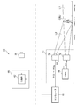
- FIG. 1 is a block diagram of an object identification system 10 according to the first embodiment.
- the object identification system 10 is mounted on a vehicle such as an automobile or a motorcycle and determines the type (category) of the object OBJ existing around the vehicle.
- the object identification system 10 mainly includes a camera 30 and an arithmetic processing unit 40.
- the camera 30 is a monocular camera and photographs the surroundings of the vehicle.
- the arithmetic processing unit 40 includes a classifier 42.
- the classifier 42 is implemented based on the learned model obtained by machine learning so that the object OBJ can be identified based on the output image IMG of the camera 30.
- the algorithm of the classifier 42 is not particularly limited, but YOLO (You Only Look Once), SSD (Single Shot Multi Box Detector), R-CNN (Region-based Convolutional Neural Network), SPPnet (Spatial Pyramid Pooling), Faster R-CNN , DSSD (Deconvolution-SSD), MaskR-CNN, etc. can be adopted, or an algorithm developed in the future can be adopted.
- FIG. 1 shows a setup for performing machine learning in addition to the object identification system 10.
- a gating camera 50 is used for machine learning of the classifier 42.
- the gating camera 50 is a camera that divides into a plurality of N (N ⁇ 2) ranges RNG 1 to RNG N in the depth direction, and changes the time difference between light projection and exposure for each range to shoot.
- the gating camera 50 generates a plurality of images IMG 1 to IMG N corresponding to a plurality of ranges RNG 1 to RNG N.
- a set of a plurality of images IMG 1 to IMG N can be obtained for each type of the object OBJ.
- the set of the plurality of images IMG 1 to IMG N thus obtained is input to the computer 60 in association with the type of the object OBJ.
- the computer 60 executes the machine learning of the classifier 42 using the set of the plurality of images IMG 1 to IMG N as learning data (training data).
- a publicly known technique may be used for the machine learning method in the computer 60, and thus the description thereof is omitted.
- the learning result finally obtained by the computer 60 is given to the arithmetic processing unit 40 to configure the classifier 42.
- the gating camera 50 includes a light projector 52, an image sensor 54 and a controller 56. Imaging by the gating camera 50 is divided into a plurality of N (N ⁇ 2) ranges RNG 1 to RNG N in the depth direction. Adjacent ranges may overlap in the depth direction at their boundaries.
- the light projector 52 irradiates the probe light L1 to the front of the vehicle in synchronization with the light projection timing signal S1 given from the controller 56.
- the probe light L1 is preferably infrared light, but is not limited thereto, and may be visible light having a predetermined wavelength.
- the image sensor 54 is capable of exposure control in synchronization with the shooting timing signal S2 given from the controller 56, and is configured to generate an image IMG.
- the image sensor 54 has sensitivity to the same wavelength as the probe light L1 and captures the reflected light (return light) L2 reflected by the object OBJ.
- the controller 56 changes the projection timing signal S1 and the shooting timing signal S2 for each range RNG to change the time difference between the projection by the projector 52 and the exposure of the image sensor 54.
- the camera 30 generates a plurality of images IMG 1 to IMG N corresponding to a plurality of ranges RNG 1 to RNG N. In the i-th image IMG i , only the objects included in the corresponding range RNG i are captured.
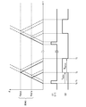
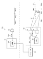
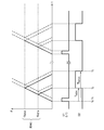
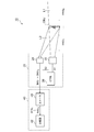
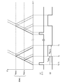
- FIG. 2 is a diagram illustrating the operation of the gating camera 50.
- FIG. 2 shows how the i-th range RNG i is measured.
- the light projector 52 emits light in synchronization with the light emission timing signal S1 during a light emission period ⁇ 1 between times t 0 and t 1 .
- a diagram of rays with time on the horizontal axis and distance on the vertical axis is shown. From the camera 30, the distance d MINi up before the boundary of the range RNG i, the distance to the far side of the boundary of the range RNG i and d MAXi.
- T MINi 2 ⁇ d MINi /c Is.
- c is the speed of light.
- T MAXi 2 ⁇ d MAXi /c Is.
- the signal S2 is generated. This is one exposure operation.
- the controller 56 may repeat the exposure operation described above a plurality of times at a predetermined cycle ⁇ 2 .
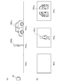
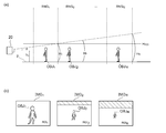
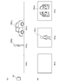
- FIGS. 3A and 3B are views for explaining acquisition of learning data using a gating camera.
- N 2.
- N 2.
- OBJ 1 and OBJ 2 are arranged in different ranges RNG 1 and RNG 2 as shown in FIG.
- OBJ 1 is a pedestrian
- OBJ 2 is a car.
- FIG. 3B shows a plurality of images IMG 1 and IMG 2 obtained in the situation of FIG.
- the image IMG 1 includes only the object OBJ 1 included in the front range RNG 1
- the image IMG 2 includes only the object OBJ 2 on the back side. That is, when viewed from the camera 30 of the object identification system 10, it is possible to separate a plurality of objects OBJ 1 and OBJ 2 that appear to overlap. Then, by inputting the plurality of images IMG 1 and IMG 2 as separate learning data to the computer 60, the classifier 42 that can identify the objects OBJ 1 and OBJ 2 as separate objects can be configured.
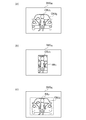
- FIG. 4A is a diagram showing an image IMGx captured by a monocular camera. As shown in FIG. 4A, in the image IMGx, two objects OBJ 1 and OBJ 2 overlap each other.
- FIG. 4B shows a bounding box BB 1 including a pedestrian (OBJ 1 ).
- the inside of the bounding box BB 1 includes information of not only a pedestrian (OBJ 1 ) but also a vehicle in the background (OBJ 2 ). Therefore, when the image IMGx in FIG. 4A is used as the learning data, the learning proceeds so that the pedestrian OBJ 1 can be identified together with the vehicle information. In other words, a single pedestrian with no vehicle in the background may be difficult to identify as a pedestrian.
- FIG. 4C shows a bounding box BB 2 including the vehicle (OBJ 2 ).
- the inside of the bounding box BB 2 includes information of not only the vehicle (OBJ 2 ) but also the front pedestrian (OBJ 1 ). Therefore, when the image IMGx in FIG. 4A is used as the learning data, the learning progresses so that the pedestrian information can be included and the vehicle OBJ 2 can be identified. In other words, it may be difficult to distinguish a single vehicle with no pedestrian on the near side from the vehicle.
- Machine learning requires a huge amount of learning data, but if you take images of an object under different conditions and conditions, learning costs will increase. Therefore, in general, an idea is made to increase one basic image into a plurality of images by "bulking". Examples of general methods for increasing the bulk include horizontal inversion of the basic image, rotation, enlargement/reduction, change of brightness value, change of contrast, and the like.
- Examples of general methods for increasing the bulk include horizontal inversion of the basic image, rotation, enlargement/reduction, change of brightness value, change of contrast, and the like.
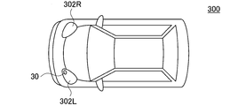
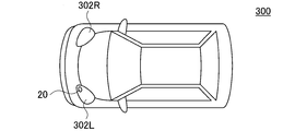
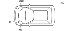
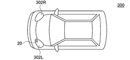
- FIG. 5 is a block diagram of an automobile including the object identification system 10.
- the automobile 300 includes headlights 302L and 302R.
- the object identification system 10 is built in at least one of the headlights 302L and 302R.
- the headlight 302 is located at the most tip of the vehicle body, and is most advantageous as a place where the camera 30 is installed in detecting surrounding objects.
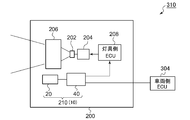
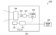
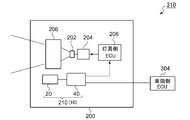
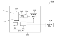
- FIG. 6 is a block diagram showing a vehicular lamp 200 including the object detection system 210.
- the vehicular lamp 200 constitutes a lamp system 310 together with the vehicle-side ECU 304.
- the vehicular lamp 200 includes a light source 202, a lighting circuit 204, and an optical system 206. Further, the vehicle lighting device 200 is provided with an object detection system 210.
- the object detection system 210 corresponds to the object identification system 10 described above, and includes a camera 30 and an arithmetic processing unit 40.
- Information on the object OBJ detected by the arithmetic processing unit 40 may be used for light distribution control of the vehicular lamp 200.
- the lamp-side ECU 208 generates an appropriate light distribution pattern based on the information on the type and the position of the object OBJ generated by the arithmetic processing device 40.
- the lighting circuit 204 and the optical system 206 operate so as to obtain the light distribution pattern generated by the lamp-side ECU 208.
- Information regarding the object OBJ detected by the arithmetic processing unit 40 may be transmitted to the vehicle-side ECU 304.
- the vehicle-side ECU may perform automatic driving based on this information.
- FIG. 7 is a block diagram of the object identification system 10A according to the first modification.
- the object identification system 10A includes a gating camera 20 instead of the camera 30 of FIG.
- the structure of the gating camera 20 is the same as that of the gating camera 50 of FIG.
- the gating camera 20 is a camera that divides into a plurality of M (M ⁇ 2) ranges RNG 1 to RNG M in the depth direction and changes the time difference between light projection and exposure for each range to shoot.
- the gating camera 20 generates a plurality of images IMG 1 to IMG M corresponding to a plurality of ranges RNG 1 to RNG M.
- the classifier 42 receives, from the gating camera 20, a plurality of images IMG 1 to IMG M corresponding to a plurality M (M ⁇ 2) ranges RNG 1 to RNG M.
- the classifier 42 is configured to be able to identify the types of objects included in the images IMG 1 to IMG M based on the plurality of images.
- a plurality of images IMG 1 to IMG N obtained by the gating camera 50 are used for learning of the classifier 42.
- the number N of ranges of the gating camera 50 and the number M of ranges of the gating camera 20 may be the same or different.
- the object identification system is divided into a plurality of ranges in the depth direction, a gating camera that captures images by changing the time difference between light projection and exposure for each range, and a plurality of images corresponding to the plurality of ranges obtained by the gating camera.
- an arithmetic processing unit capable of identifying the type of the object based on the above.
- the arithmetic processing device includes a plurality of classifiers having different algorithms, selects a classifier according to the range, and performs object recognition.
- the processing device may use a classifier of the YOLO (You Only Look Once) algorithm for image processing in a range with a short distance.
- YOLO is unsuitable for identifying small objects, but has the advantage of being fast. Since an object included in an image has a larger distance to the object, the use of YOLO enables highly accurate and high-speed detection/identification of an object included in a range having a short distance.
- the processor may use a classifier of SSD (Single Shot MultiBox Detector) algorithm for image processing in a range with a long distance.
- SSD Single Shot MultiBox Detector
- the SSD is slow in processing speed, but has an advantage that even a small object can be detected with high accuracy. Since the object included in the image has a smaller distance to the object, the SSD can be used to detect and identify the object included in the far range with high accuracy.
- the processor may use a classifier with a relatively high-speed algorithm for image processing in a range in which the distance is relatively short.
- the arithmetic processing device may use a classifier having a relatively high accuracy algorithm for image processing in a range having a relatively long distance.
- FIG. 8 is a block diagram of the object identification system 10 according to the second embodiment.
- the object identification system 10 is mounted on a vehicle such as an automobile or a motorcycle and determines the type (category) of the object OBJ existing around the vehicle.
- the object identification system 10 mainly includes a gating camera 20 and an arithmetic processing device 40.
- the gating camera 20 includes a light projector 22, an image sensor 24, and a controller 26. Imaging by the gating camera 20 is divided into a plurality of N (N ⁇ 2) ranges RNG 1 to RNG N in the depth direction. Adjacent ranges may overlap in the depth direction at their boundaries.
- the light projector 22 emits the probe light L1 to the front of the vehicle in synchronization with the light projection timing signal S1 given from the controller 26.
- the probe light L1 is preferably infrared light, but is not limited thereto, and may be visible light having a predetermined wavelength.
- the image sensor 24 is capable of exposure control in synchronization with the shooting timing signal S2 given from the controller 26, and is configured to be able to generate an image IMG.
- the image sensor 24 has sensitivity to the same wavelength as the probe light L1 and captures the reflected light (return light) L2 reflected by the object OBJ.
- the controller 26 changes the projection timing signal S1 and the shooting timing signal S2 for each range RNG to change the time difference between the projection by the projector 22 and the exposure of the image sensor 24.
- the gating camera 20 generates a plurality of images IMG 1 to IMG N corresponding to a plurality of ranges RNG 1 to RNG N. In the i-th image IMG i , only the objects included in the corresponding range RNG i are captured.
- FIG. 9 is a diagram for explaining the operation of the gating camera 20.
- FIG. 9 shows how the i-th range RNG i is measured.
- the light projector 22 emits light in synchronization with the light emission timing signal S1 during the light emission period ⁇ 1 between times t 0 and t 1 .
- a diagram of rays with time on the horizontal axis and distance on the vertical axis is shown. From gating camera 20, the distance d MINi up before the boundary of the range RNG i, the distance to the far side of the boundary of the range RNG i and d MAXi.
- T MINi 2 ⁇ d MINi /c Is.
- c is the speed of light.
- T MAXi 2 ⁇ d MAXi /c Is.
- the signal S2 is generated. This is one exposure operation.
- the controller 26 may repeat the above-mentioned exposure operation a plurality of times at a predetermined cycle ⁇ 2 .
- the arithmetic processing unit 40 is configured to be able to identify the type of object based on the plurality of images IMG 1 to IMG N corresponding to the plurality of ranges RNG 1 to RNG N obtained by the gating camera 20.
- the arithmetic processing unit 40 can be implemented by a combination of a processor (hardware) such as a CPU (Central Processing Unit), an MPU (Micro Processing Unit), and a microcomputer, and a software program executed by the processor (hardware).
- the arithmetic processing unit 40 may be a combination of a plurality of processors. Alternatively, the arithmetic processing unit 40 may be composed of only hardware.
- the arithmetic processing unit 40 includes a plurality of M (M ⁇ 2) classifiers 42_1 to 42_M having different algorithms.
- the selector 44 supplies each image IMG to the classifier 42 selected according to the range RNG.
- the classifier 42 processes the given image IMG to detect and classify (identify) the objects contained therein.
- the number M of classifiers 42 may be the same as or smaller than the number N of range RNGs.
- One of the multiple algorithms may be an algorithm that is fast but has low accuracy (in other words, low detection accuracy for small objects). Further, another one of the plurality of algorithms is a low-speed algorithm, which may have high accuracy (in other words, high detection accuracy for small objects).
- the arithmetic processing unit 40 may use a relatively high-speed and low-precision algorithm classifier for image processing in a range in which the distance is relatively short. Further, the arithmetic processing device 40 may use a classifier having a relatively low speed and high accuracy for image processing in a range in which the distance is relatively long.
- the YOLO (You Only Look Once) algorithm is suitable as one of the multiple algorithms.
- another one of the plurality of algorithms is preferably an SSD (Single Shot MultiBox Detector) algorithm.
- FIG. 10A is a time chart explaining the operation of the object identification system 10 of FIG.
- the classifier 42_1 of the YOLO algorithm is assigned to the processing of the image IMG 1 of the first range RNG 1
- the SSD of the SSD is used for the processing of the image IMG 2 of the second range RNG 2. Let us assign the algorithm classifier 42_2.
- an image IMG 1 range RNG 1 is obtained, it is processed by the classifier 42_1 of YOLO algorithm.
- an image IMG 2 range RNG 2 is obtained and processed by classifier 42_2 its SSD algorithm.
- the object identification system 10 two or three or more algorithm classifiers having a complementary relationship with each other are used, and the classifiers are assigned to each imaging range, thereby making it possible to accurately detect near objects and distant objects. Moreover, it can be detected in a short time.
- YOLO is unsuitable for identifying small objects, but has the advantage of being fast.
- the object included in the image is larger when the distance to the object is shorter. Therefore, by using YOLO for image processing of the range RNG 1 having a short distance, it is possible to detect and identify an object included in a range having a short distance with high accuracy and high speed.
- SSD is inferior in processing speed to YOLO, but has the advantage that even small objects can be detected with high accuracy. Since the object included in the image has a smaller distance to the object, the SSD can be used to detect and identify the object included in the far range with high accuracy.
- FIG. 10B is a time chart for explaining the operation of the object identification system according to the comparative technique. If the SSD algorithm is applied to all the images IMG 1 and IMG 2 , highly accurate detection is possible regardless of the distance of the object. However, the detection time required to perform object recognition for all ranges is longer than that in FIG. In other words, the comparison technique means that the frame rate is reduced. In order to realize a high frame rate in the comparative technique, a high-speed CPU or microcomputer is required for the arithmetic processing unit 40, and the cost of the object identification system 10 becomes high.
- SSD high-precision algorithm
- both high detection accuracy and high frame rate can be achieved without using very expensive (high speed) hardware. be able to.
- FIG. 11 is a block diagram of an automobile including the object identification system 10.
- the automobile 300 includes headlights 302L and 302R.
- the object identification system 10 is built in at least one of the headlights 302L and 302R.
- the headlight 302 is located at the most tip end of the vehicle body, and is most advantageous as an installation location of the gating camera 20 in detecting surrounding objects.
- FIG. 12 is a block diagram showing a vehicle lamp 200 including an object detection system 210.
- the vehicular lamp 200 constitutes a lamp system 310 together with the vehicle-side ECU 304.
- the vehicular lamp 200 includes a light source 202, a lighting circuit 204, and an optical system 206. Further, the vehicle lighting device 200 is provided with an object detection system 210.
- the object detection system 210 corresponds to the above-described object identification system 10, and includes a gating camera 20 and a calculation processing device 40.
- Information on the object OBJ detected by the arithmetic processing unit 40 may be used for light distribution control of the vehicular lamp 200.
- the lamp-side ECU 208 generates an appropriate light distribution pattern based on the information on the type and the position of the object OBJ generated by the arithmetic processing device 40.
- the lighting circuit 204 and the optical system 206 operate so as to obtain the light distribution pattern generated by the lamp-side ECU 208.
- Information regarding the object OBJ detected by the arithmetic processing unit 40 may be transmitted to the vehicle-side ECU 304.
- the vehicle-side ECU may perform automatic driving based on this information.
- the classifier 42_1 of the YOLO algorithm is assigned to the processing of the images IMG 1 to IMG k of the first to kth ranges RNG 1 to RNG k , and the k+1th to Nth ranges are assigned.
- the SSD algorithm classifier 42_2 may be assigned to the processing of the images IMG k+1 to IMG N of RNG k+1 to RNG N.
- YOLO and SSD have been described as a plurality of algorithms, but this is not the only option.
- Known object recognition algorithms include R-CNN (Region-based Convolutional Neural Network), SPPnet (Spatial Pyramid Pooling), Faster R-CNN, DSSD (Deconvolution-SSD), and Mask R-CNN. It goes without saying that any of the above can be adopted, or an algorithm developed in the future may be adopted.
- the object identification system is divided into a plurality of ranges in the depth direction, a gating camera that captures images by changing the time difference between light projection and exposure for each range, and a plurality of images corresponding to the plurality of ranges obtained by the gating camera.
- a scaler that scales with a coefficient specified for each range
- a classifier that can identify the type of object based on each of the plurality of scaled images.
- the same object size can be made uniform in a plurality of images input to the classifier.
- the discriminating power of the classifier can be enhanced or the learning cost can be reduced.
- the coefficient may be smaller in the closer range and larger in the far range.
- the coefficient of the reference range may be set to 1, the coefficient of the range closer to the reference range may be set to be smaller than 1, and the coefficient of the range far from the reference range may be set to be larger than 1. This can simplify the scaler processing. Further, in learning, it is sufficient to prioritize and use the image captured by arranging the object in the reference range, and it is possible to reduce the number of times of capturing the object in the range other than the reference range.
- FIG. 13 is a block diagram of the object identification system 10 according to the third embodiment.
- the object identification system 10 is mounted on a vehicle such as an automobile or a motorcycle and determines the type (category) of the object OBJ existing around the vehicle.
- the object identification system 10 mainly includes a gating camera 20 and an arithmetic processing device 40.
- the gating camera 20 includes a light projector 22, an image sensor 24, and a controller 26. Imaging by the gating camera 20 is divided into a plurality of N (N ⁇ 2) ranges RNG 1 to RNG N in the depth direction. Adjacent ranges may overlap in the depth direction at their boundaries.
- the light projector 22 emits the probe light L1 to the front of the vehicle in synchronization with the light projection timing signal S1 given from the controller 26.
- the probe light L1 is preferably infrared light, but is not limited thereto, and may be visible light having a predetermined wavelength.
- the image sensor 24 is capable of exposure control in synchronization with the shooting timing signal S2 given from the controller 26, and is configured to generate an image IMG.
- the image sensor 24 has sensitivity to the same wavelength as the probe light L1 and captures the reflected light (return light) L2 reflected by the object OBJ.
- the controller 26 changes the projection timing signal S1 and the shooting timing signal S2 for each range RNG to change the time difference between the projection by the projector 22 and the exposure of the image sensor 24.
- the gating camera 20 generates a plurality of images IMG 1 to IMG N corresponding to a plurality of ranges RNG 1 to RNG N. In the i-th image IMG i , only the objects included in the corresponding range RNG i are captured.
- FIG. 14 is a diagram illustrating the operation of the gating camera 20.
- FIG. 14 shows how the i-th range RNG i is measured.
- the light projector 22 emits light in synchronization with the light emission timing signal S1 during the light emission period ⁇ 1 between times t 0 and t 1 .
- a diagram of rays with time on the horizontal axis and distance on the vertical axis is shown. From gating camera 20, the distance d MINi up before the boundary of the range RNG i, the distance to the far side of the boundary of the range RNG i and d MAXi.
- T MINi 2 ⁇ d MINi /c Is.
- c is the speed of light.
- T MAXi 2 ⁇ d MAXi /c Is.
- the signal S2 is generated. This is one exposure operation.
- the controller 26 may repeat the above-mentioned exposure operation a plurality of times at a predetermined cycle ⁇ 2 .
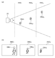
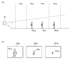
- FIGS. 15A and 15B are views for explaining an image obtained by the gating camera 20.
- the object (pedestrian) on the range RNG 2 OBJ 2 are present, there is an object (vehicle) OBJ 3 to the range RNG 3.
- FIG. 15B shows a plurality of images IMG 1 to IMG 3 obtained in the situation of FIG. 15A.
- image sensor When taking an image IMG 1, image sensor to be exposed only by reflected light from the range RNG 1, the image IMG 1 is not reflected any object.
- the image sensor When the image IMG 2 is taken, the image sensor is exposed only by the reflected light from the range RNG 2, so only the object OBJ 2 is shown in the image IMG 2 .
- the image sensor when the image IMG 3 is taken, the image sensor is exposed only by the reflected light from the range RNG 3, so that only the object OBJ 3 is shown in the image IMG 3 .
- the object can be separated and photographed for each range.
- the arithmetic processing unit 40 is configured to be able to identify the type of object based on the plurality of images IMG 1 to IMG N corresponding to the plurality of ranges RNG 1 to RNG N obtained by the gating camera 20.
- the arithmetic processing unit 40 includes a classifier 42 that is implemented based on the model generated by machine learning.
- the algorithm of the classifier 42 is not particularly limited, but YOLO (You Only Look Once), SSD (Single Shot MultiBox Detector), R-CNN (Region-based Convolutional Neural Network), SPPnet (Spatial Pyramid Pooling), Faster R-CNN , DSSD (Deconvolution -SSD), Mask R-CNN, etc. can be adopted, or an algorithm developed in the future can be adopted.
- the arithmetic processing unit 40 can be implemented by a combination of a processor (hardware) such as a CPU (Central Processing Unit), an MPU (Micro Processing Unit), and a microcomputer, and a software program executed by the processor (hardware).
- a processor such as a CPU (Central Processing Unit), an MPU (Micro Processing Unit), and a microcomputer
- the arithmetic processing unit 40 may be a combination of a plurality of processors. Alternatively, the arithmetic processing unit 40 may be composed of only hardware.
- a huge amount of learning data (training data) is used for training the classifier 42.
- Image data taken by a gating camera or a normal camera is used as the learning data.
- FIGS. 16A and 16B are views for explaining images obtained by the gating camera 20.
- the gating camera 20 has a horizontal field angle (viewing angle) ⁇ and a vertical field angle determined by its own sensor size and optical system. Since the gating camera 20 shoots at the same angle of view regardless of the range, when shooting the same object located at different distances, the shooting magnification varies depending on the distance to the object. Therefore, as shown in FIG. 16B, the farther the object, the smaller the object, and the closer the object, the larger the image. It should be noted that this feature is not limited to the gating camera, and is the same in the case of shooting with a normal camera.
- the arithmetic processing unit 40 for any of the image IMG 1 ⁇ IMG 3, discrimination for classifying objects OBJ 1 ⁇ OBJ 3 included in each of the pedestrian is required.
- a method is used in which images obtained by shooting objects of a certain category at different distances are prepared and used as learning data. Further, a method of enlarging or reducing a basic image obtained by photographing an object at a certain distance to generate a plurality of images and using them as learning data is also adopted (called bulk increase).
- the arithmetic processing unit 40 includes a scaler 46 provided in the preceding stage of the classifier 42.
- the relationship between the range and the coefficient may be held in a table or in the form of an arithmetic expression.
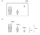
- 17A to 17C are diagrams illustrating an example of scaling processing by the scaler 46.
- N 3.
- the coefficients K 1 to K 3 are determined so that the sizes (the number of vertical and horizontal pixels x and y) of the object OBJ included in the images IMGs 1 to IMGs 3 after the scaling process are close to each other.
- the reference range may be selected from a plurality of ranges. Then, the coefficient of the reference range is set to 1 or in the vicinity thereof.
- the center range RNG 2 is the reference range and the coefficient K 2 is chosen to be 1.
- the image data IMGs 1 to IMGs N after the scaling processing by the scaler 46 is input to the classifier 42.
- the classifier 42 identifies the type of the object OBJ included in each image data based on each of the image data IMGs 1 to IMGs N.
- the above is the configuration of the object identification system 10.
- the images input to the classifier 42 are scaled so that the same object approaches the same size (number of pixels). Therefore, the classifier 42 can detect an object and identify its category without depending on the distance to the object. This brings about an improvement in the identification rate (correct answer rate) of the classifier 42.
- Adopting this object identification system 10 also has the advantage that the learning cost of the classifier 42 can be reduced. That is, at the time of learning, the object may be arranged with emphasis on the range where the scaling coefficient is close to 1, and the image obtained at that time may be used as learning data to optimize the parameters of the classifier 42. When the range is greatly deviated from 1, the number of times of photographing can be reduced.
- FIG. 18 is a block diagram of an automobile including the object identification system 10.
- the automobile 300 includes headlights 302L and 302R.
- the object identification system 10 is built in at least one of the headlights 302L and 302R.
- the headlight 302 is located at the most tip end of the vehicle body, and is most advantageous as an installation location of the gating camera 20 in detecting surrounding objects.
- FIG. 19 is a block diagram showing a vehicular lamp 200 including the object detection system 210.
- the vehicular lamp 200 constitutes a lamp system 310 together with the vehicle-side ECU 304.
- the vehicular lamp 200 includes a light source 202, a lighting circuit 204, and an optical system 206. Further, the vehicle lighting device 200 is provided with an object detection system 210.
- the object detection system 210 corresponds to the above-described object identification system 10, and includes a gating camera 20 and a calculation processing device 40.
- Information on the object OBJ detected by the arithmetic processing unit 40 may be used for light distribution control of the vehicular lamp 200.
- the lamp-side ECU 208 generates an appropriate light distribution pattern based on the information on the type and the position of the object OBJ generated by the arithmetic processing device 40.
- the lighting circuit 204 and the optical system 206 operate so as to obtain the light distribution pattern generated by the lamp-side ECU 208.
- Information regarding the object OBJ detected by the arithmetic processing unit 40 may be transmitted to the vehicle-side ECU 304.
- the vehicle-side ECU may perform automatic driving based on this information.
- the reference range coefficient is set to 1 and the other range coefficients are set to be smaller or larger than 1 with reference to a range near the center of the plurality of ranges.
- the front range may be used as the reference range, and the coefficient of the back range may be made larger than 1.
- the innermost range may be set as the reference range, and the coefficient of the front side range may be smaller than 1.
- Modification 2 Although the reference range is one, the reference range may be plural. Modification 2 will be described with reference to FIG. FIGS. 20A and 20B are views for explaining an image obtained by the gating camera 20.
- the number N of ranges is four.
- the multiple ranges are divided into multiple sets. Each set includes at least one range, and the reference range is provided for each set.
- RNG 1 and RNG 2 are defined as a first set
- RNG 3 and RNG 4 are defined as a second set. Focusing on the first set, one of the ranges RNG 1 and RNG 2 included in the first set may be set as a reference range, and the coefficients of the remaining ranges may be set so that the size of the object approaches that of the reference range.
- one of the ranges RNG 3 and RNG 4 included in the second set may be defined as a reference range, and the coefficients of the remaining ranges may be set so that the size of the object approaches that of the reference range. ..
- machine learning may be performed by intensively using an image obtained in a situation where an object is located in the reference range for each set of ranges.
- the object identification system divides the object into a plurality of ranges in the depth direction, changes the time difference between the light projection and the exposure for each range, and shoots the image to generate a plurality of images corresponding to the plurality of ranges.
- An arithmetic processing unit configured to be able to identify the type of object included in each of the plurality of images under the constraint that the region in which the object can exist is limited.
- the location of the object to be identified is limited depending on its type. For example, pedestrians and car traffic participants exist on the ground, not in the air. That is, the positions where traffic participants and the like can exist in the image are restricted to the area near the ground. In a gating camera, when a plurality of images are captured at the same angle of view, the area near the ground changes for each distance from the camera, that is, for each image.
- the amount of calculation processing can be reduced.
- the object identification system may include, for each of the plurality of images, a pre-processing unit that trims the image in the region of interest, and a classifier that processes the output of the pre-processing unit. In this case, the size of the image given to the classifier becomes small, so that the amount of calculation processing can be reduced.
- the object identification system may include a preprocessing unit that masks an image outside the region of interest for each of the plurality of images, and a classifier that processes the output of the preprocessing unit.
- the preprocessing unit may fill the outside of the region of interest with a single color.
- the position information of the object may be reflected in the determination of the type of the object after or inside the classifier.
- the arithmetic processing unit detects a type and a position of an object included in each of a plurality of images, generates a plurality of detection data corresponding to the plurality of images, and a plurality of detection data, and receives the plurality of detection data.
- a post-processing unit that determines whether or not the position of the object included in is included in the region of interest specific to the original image.
- ⁇ Region of interest may be larger for images in the closer range and smaller for images in the farther range.
- the area of interest may be smaller in height as the image in the farther range. This can reduce the amount of calculation processing for detecting an object near the ground.
- the area of interest may be narrower in the farther range image.
- FIG. 21 is a block diagram of the object identification system 10 according to the embodiment 4-1.
- the object identification system 10 is mounted on a vehicle such as an automobile or a motorcycle, and determines the type (also referred to as category or class) of an object OBJ existing around the vehicle.
- the object identification system 10 mainly includes a gating camera 20 and an arithmetic processing device 40.
- the gating camera 20 includes a light projector 22, an image sensor 24, and a controller 26. Imaging by the gating camera 20 is divided into a plurality of N (N ⁇ 2) ranges RNG 1 to RNG N in the depth direction. Adjacent ranges may overlap in the depth direction at their boundaries.
- the light projector 22 emits the probe light L1 to the front of the vehicle in synchronization with the light projection timing signal S1 given from the controller 26.
- the probe light L1 is preferably infrared light, but is not limited thereto, and may be visible light having a predetermined wavelength.
- the image sensor 24 is capable of exposure control in synchronization with the shooting timing signal S2 given from the controller 26, and is configured to generate an image IMG.
- the image sensor 24 has sensitivity to the same wavelength as the probe light L1 and captures the reflected light (return light) L2 reflected by the object OBJ.
- the controller 26 changes the projection timing signal S1 and the shooting timing signal S2 for each range RNG to change the time difference between the projection by the projector 22 and the exposure of the image sensor 24.
- the gating camera 20 generates a plurality of images IMG 1 to IMG N corresponding to a plurality of ranges RNG 1 to RNG N. In the i-th image IMG i , only the objects included in the corresponding range RNG i are captured.
- FIG. 22 is a diagram for explaining the operation of the gating camera 20.
- FIG. 22 shows how the i-th range RNG i is measured.
- the light projector 22 emits light in synchronization with the light emission timing signal S1 during the light emission period ⁇ 1 between times t 0 and t 1 .
- a diagram of rays with time on the horizontal axis and distance on the vertical axis is shown. From gating camera 20, the distance d MINi up before the boundary of the range RNG i, the distance to the far side of the boundary of the range RNG i and d MAXi.
- T MINi 2 ⁇ d MINi /c Is.
- c is the speed of light.
- T MAXi 2 ⁇ d MAXi /c Is.
- the signal S2 is generated. This is one exposure operation.
- the controller 26 may repeat the above-mentioned exposure operation a plurality of times at a predetermined cycle ⁇ 2 .
- FIG. 23A and 23B are views for explaining an image obtained by the gating camera 20.
- the object range RNG 2 (pedestrian) OBJ 2 are present, there is an object (vehicle) OBJ 3 to the range RNG 3.
- FIG. 23B shows a plurality of images IMG 1 to IMG 3 obtained in the situation of FIG. When taking an image IMG 1, image sensor to be exposed only by reflected light from the range RNG 1, the image IMG 1 is not reflected any object.
- the image sensor When the image IMG 2 is taken, the image sensor is exposed only by the reflected light from the range RNG 2, so only the object OBJ 2 is shown in the image IMG 2 .
- the image sensor when the image IMG 3 is taken, the image sensor is exposed only by the reflected light from the range RNG 3, so that only the object OBJ 3 is shown in the image IMG 3 .
- the object can be separated and photographed for each range.
- the arithmetic processing unit 40 is configured to be able to identify the type of object based on the plurality of images IMG 1 to IMG N corresponding to the plurality of ranges RNG 1 to RNG N obtained by the gating camera 20.
- the arithmetic processing unit 40 includes a classifier 42 implemented based on a trained model generated by machine learning.
- the algorithm of the classifier 42 is not particularly limited, YOLO (You Only Look Once), SSD (Single Shot MultiBox Detector), R-CNN (Region-based Convolutional Neural Network), SPPnet (Spatial Pyramid Pooling), Faster R-CNN , DSSD (Deconvolution -SSD), Mask R-CNN, etc. can be adopted, or an algorithm developed in the future can be adopted.
- the arithmetic processing unit 40 can be implemented by a combination of a processor (hardware) such as a CPU (Central Processing Unit), an MPU (Micro Processing Unit), and a microcomputer, and a software program executed by the processor (hardware).
- a processor such as a CPU (Central Processing Unit), an MPU (Micro Processing Unit), and a microcomputer
- the arithmetic processing unit 40 may be a combination of a plurality of processors. Alternatively, the arithmetic processing unit 40 may be composed of only hardware.
- a unique region of interest is defined for each image, that is, for each range.
- the ROI is a region where an object can exist.
- Classifier 42 for each image IMG i, the position of a possible object OBJ is, the image IMG i of constraints to be limited to the specific ROI i original, the object included in the image IMG i Identify the type.
- the type information may indicate the possibility (probability) of each of the plurality of types, or may include the identifier of the type with the highest probability.
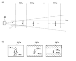
- 24A and 24B are diagrams for explaining the ROI.
- 24A is a side view
- FIG. 24B shows an image captured by the gating camera 20.
- the imaging range of the gating camera 20 is ⁇ vertically with respect to the horizontal axis in terms of the angle of view.
- the image IMG i of the i-th range RNG i shows an object in the range below the height H i .
- the range where pedestrians and automobiles are present is limited to a predetermined range (0 to H ROI ). Then, it can be considered that there is no detection symmetric object in the range of H ROI to H i . Therefore, as shown in FIG. 24B, for each image IMG i , the range below H ROI can be set as ROI i, and the range above H ROI can be set as an exclusion area (hatching). Specifically, for the i-th image IMG i , the range of the ratio of H ROI /H i from the lower end may be set as ROI i . The ROI is larger in the image in the closer range and smaller in the image in the far range.
- a preprocessing unit 46 is provided in the preceding stage of the classifier 42.
- the preprocessing unit 46 trims the image in the ROI from each image IMG i .
- the classifier 42 processes the trimming images IMGt 1 to IMGt N output from the preprocessing unit 46.
- FIG. 25A and 25B are diagrams for explaining the operation of the object identification system 10 in FIG.
- FIG. 25A shows the image IMG i of the i-th range
- FIG. 25B shows the image IMGt i after trimming.
- FIG. 25A In the image IMG i of FIG. 25A, three figures X, Y, X are shown.
- the figure X is included in ROI i
- the figures Y and Z are outside ROI i . Therefore, the figures Y and Z are unlikely to be pedestrians or automobiles.
- the image IMGt i trimmed by the preprocessing unit 46 includes only the figure X.
- the graphics Y and Z are excluded from the target of the arithmetic processing, and only the graphic X is the target of the identification processing. As a result, the processing amount of the processing device 40 can be reduced.
- the identification rate of the object identification system 10 can be improved.
- Embodiment 4-2 In Embodiment 4-1, the target of the arithmetic processing is limited to the ROI by the preprocessing of the classifier 42, but it is not limited to this. In the embodiment 4-2, the constraint condition that the position where the object OBJ can exist is limited to the region of interest peculiar to each of the plurality of images by the post-processing of the classifier 42 or the internal processing is imposed. ..
- FIG. 26 is a block diagram of object identification system 10A according to Embodiment 4-2.
- the arithmetic processing device 40 ⁇ /b>A includes a post-processing unit 48 that is provided after the classifier 42.
- the classifier 42 generates, for each of the plurality of images IMG 1 to IMG N generated by the gating camera 20, detection data OUT 1 to OUT N indicating the position and type of the object included in each image.
- the post-processing unit 48 receives the detection data OUT 1 to OUT N generated by the classifier 42.
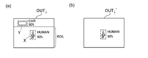
- FIG. 27A and 27B are diagrams for explaining the operation of the object identification system 10A of FIG.
- FIG. 27A is a diagram schematically showing the detection data OUT i regarding the i-th range as image data.
- the detection data OUT i includes two bounding boxes X and Y.
- An object included in one of the bounding boxes X is determined to have a 90% probability of being a pedestrian (Human), and an object included in another bounding box Y has an 80% probability of being a car. Has been determined.
- the post-processing unit 48 deletes the object outside the ROI, and outputs the deleted detection data OUT i ′.
- the calculation processing amount in the classifier 42 cannot be reduced, but the object identification rate can be improved.
- each image may include a portion below the ground.
- no object can exist in the range below the ground 2 ( ⁇ 0) in addition to the range above the respective images (H ROI to H i ). It may be treated as an area. As a result, the amount of calculation processing in the calculation processing device 40 can be further reduced.
- the range in which an object should be detected can be limited to the left and right. For example, it can be said that it is not necessary to immediately detect a pedestrian who is laterally separated from the vehicle by several tens of meters. Therefore, a detection range may be defined in the lateral direction centering on the own vehicle, and a portion corresponding to the detection range in each image IMG i may be set as ROI i . As a result, the amount of calculation processing can be further reduced.
- the pre-processing unit 46 may mask an image outside the ROI from each image IMG i .
- the preprocessing unit 46 may fill the outside of the ROI with a single color (for example, black or white).
- the classifier 42 processes the masked image IMGm i .
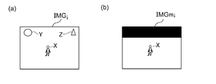
- 30A and 30B are diagrams illustrating the operation of the object identification system 10 according to the third modification.
- FIG. 30A In the image IMG i of FIG. 30A, three figures X, Y, X are shown.
- the figure X is included in the ROI, and the figures Y and Z are outside the ROI. Therefore, the figures Y and Z are unlikely to be pedestrians or automobiles.
- the preprocessing unit 46 masks the outside of the ROI, so that the graphics Y and Z are removed from the masked image IMGm i .
- the graphics Y and Z are excluded from the target of the arithmetic processing, and only the graphic X is the target of the identification processing. As a result, the processing amount of the processing device 40 can be reduced.
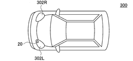
- FIG. 31 is a block diagram of an automobile including the object identification system 10.
- the automobile 300 includes headlights 302L and 302R.
- the object identification system 10 is built in at least one of the headlights 302L and 302R.
- the headlight 302 is located at the most tip end of the vehicle body, and is most advantageous as an installation location of the gating camera 20 in detecting surrounding objects.
- FIG. 32 is a block diagram showing a vehicular lamp 200 including the object detection system 210.
- the vehicular lamp 200 constitutes a lamp system 310 together with the vehicle-side ECU 304.
- the vehicular lamp 200 includes a light source 202, a lighting circuit 204, and an optical system 206. Further, the vehicle lighting device 200 is provided with an object detection system 210.
- the object detection system 210 corresponds to the above-described object identification system 10, and includes a gating camera 20 and a calculation processing device 40.
- Information on the object OBJ detected by the arithmetic processing unit 40 may be used for light distribution control of the vehicular lamp 200.
- the lamp-side ECU 208 generates an appropriate light distribution pattern based on the information on the type and the position of the object OBJ generated by the arithmetic processing device 40.
- the lighting circuit 204 and the optical system 206 operate so as to obtain the light distribution pattern generated by the lamp-side ECU 208.
- Information regarding the object OBJ detected by the arithmetic processing unit 40 may be transmitted to the vehicle-side ECU 304.
- the vehicle-side ECU may perform automatic driving based on this information.
- V Fifth aspect of the present invention
- the object identification system divides the object into a plurality of ranges in the depth direction, changes the time difference between the light projection and the exposure for shooting for each range, and generates a plurality of images corresponding to the plurality of ranges, and a gating camera for each range.
- a permissible range of the size of the object image captured in the corresponding image is defined, and an arithmetic processing unit configured to be able to identify the type of the object image captured in each image based on the permissible range.
- the size of the object image in the image changes depending on the distance to the object.
- the distance to the object included in one image can be obtained from the information in the depth direction of the corresponding range. That is, when an object located in a certain range is taken, the size of the object image shown in the image is restricted to a certain range. Therefore, by defining this range as the allowable range, the identification rate of the object can be increased or the amount of calculation processing can be reduced.
- the arithmetic processing device for each of the plurality of images, detects the type and size of the object image appearing in each of the plurality of images, and generates a plurality of detection data corresponding to the plurality of images; And a post-processing unit that determines whether or not the size of the object image included in is included in the allowable range.
- the arithmetic processing device for each of the plurality of images, a pre-processing unit that divides the sub-image for each object image that appears in it, and if the size of the sub-image that is divided by the pre-processing unit is within the allowable range, And a classifier that determines the type of the included object image.
- the allowable range may be specified in the vertical direction.
- the allowable range may be defined in the lateral direction.
- the allowable range may be specified individually for each type of object image. This can further increase the identification rate of the object.
- the allowable range may be larger in the closer range and smaller in the farther range.
- the allowable range may have a smaller height in a farther range.
- the allowable range may be narrower as it is farther away.
- FIG. 33 is a block diagram of the object identification system 10C according to the embodiment 5-1.
- the object identification system 10C is mounted on a vehicle such as an automobile or a motorcycle and determines the type (category or class) of the object OBJ existing around the vehicle.
- the object identification system 10C mainly includes a gating camera 20 and an arithmetic processing device 40C.
- the gating camera 20 includes a light projector 22, an image sensor 24, and a controller 26. Imaging by the gating camera 20 is divided into a plurality of N (N ⁇ 2) ranges RNG 1 to RNG N in the depth direction. Adjacent ranges may overlap in the depth direction at their boundaries.
- the light projector 22 emits the probe light L1 to the front of the vehicle in synchronization with the light projection timing signal S1 given from the controller 26.
- the probe light L1 is preferably infrared light, but is not limited thereto, and may be visible light having a predetermined wavelength.
- the image sensor 24 is capable of exposure control in synchronization with the shooting timing signal S2 given from the controller 26, and is configured to be able to generate an image IMG.
- the image sensor 24 has sensitivity to the same wavelength as the probe light L1 and captures the reflected light (return light) L2 reflected by the object OBJ.
- the controller 26 changes the projection timing signal S1 and the shooting timing signal S2 for each range RNG to change the time difference between the projection by the projector 22 and the exposure of the image sensor 24.
- the gating camera 20 generates a plurality of images IMG 1 to IMG N corresponding to a plurality of ranges RNG 1 to RNG N. In the i-th image IMG i , only the objects included in the corresponding range RNG i are captured.
- FIG. 34 is a diagram for explaining the operation of the gating camera 20.
- FIG. 34 shows how the i-th range RNG i is measured.
- the light projector 22 emits light in synchronization with the light emission timing signal S1 during the light emission period ⁇ 1 between times t 0 and t 1 .
- a diagram of rays with time on the horizontal axis and distance on the vertical axis is shown. From gating camera 20, the distance d MINi up before the boundary of the range RNG i, the distance to the far side of the boundary of the range RNG i and d MAXi.
- T MINi 2 ⁇ d MINi /c Is.
- c is the speed of light.
- T MAXi 2 ⁇ d MAXi /c Is.
- the signal S2 is generated. This is one exposure operation.
- the controller 26 may repeat the above-mentioned exposure operation a plurality of times at a predetermined cycle ⁇ 2 .
- FIGS. 35A and 35B are views for explaining images obtained by the gating camera 20.
- the object range RNG 2 (pedestrian) OBJ 2 are present, there is an object (vehicle) OBJ 3 to the range RNG 3.
- FIG. 35(b) shows a plurality of images IMG 1 to IMG 3 obtained in the situation of FIG. 35(a).
- the image sensor is exposed only by the reflected light from the range RNG 1, so that no image of the object is captured in the image IMG 1 .
- the image sensor When the image IMG 2 is taken, the image sensor is exposed only by the reflected light from the range RNG 2, so that only the object image OBJ 2 is shown in the image IMG 2 .
- the image sensor when the image IMG 3 is taken, the image sensor is exposed only by the reflected light from the range RNG 3, so that only the object image OBJ 3 appears in the image IMG 3 .
- the object can be separated and photographed for each range.
- the arithmetic processing unit 40C is configured to be able to identify the type of object based on the plurality of images IMG 1 to IMG N corresponding to the plurality of ranges RNG 1 to RNG N obtained by the gating camera 20.
- the arithmetic processing unit 40C includes a classifier 42 that is implemented based on the learned model generated by machine learning.
- the algorithm of the classifier 42 is not particularly limited, but YOLO (You Only Look Once), SSD (Single Shot MultiBox Detector), R-CNN (Region-based Convolutional Neural Network), SPPnet (Spatial Pyramid Pooling), Faster R-CNN , DSSD (Deconvolution -SSD), Mask R-CNN, etc. can be adopted, or an algorithm developed in the future can be adopted.
- the arithmetic processing unit 40C can be implemented by a combination of a processor (hardware) such as a CPU (Central Processing Unit), MPU (Micro Processing Unit), and a microcomputer, and a software program executed by the processor (hardware).
- a processor such as a CPU (Central Processing Unit), MPU (Micro Processing Unit), and a microcomputer
- the arithmetic processing unit 40C may be a combination of a plurality of processors. Alternatively, the arithmetic processing unit 40C may be configured only by hardware.
- the range of the size of the object image that appears in the corresponding image (called the allowable range) is specified.
- the classifier 42 identifies the type of the object image included in each of the plurality of images IMG, on the assumption that the size of the object image to be detected is included in the allowable range.
- the detection data OUT includes information on the bounding box of each object, the height and width of the bounding box can be used as the size information of the object.
- the type information may indicate the possibility (belonging probability) of each of the plurality of types, or may include the identifier of the type having the highest belonging probability.
- FIGS. 36(a) and 36(b) are diagrams for explaining images photographed for each range.
- FIG. 36A is a side view
- FIG. 36B shows an image captured by the gating camera 20.
- the imaging range of the gating camera 20 is ⁇ in the vertical direction with respect to the horizontal axis in terms of the angle of view.
- the size of the object image shown in each image becomes smaller as the range becomes farther.
- FIG. 37 is a diagram for explaining the allowable range.
- the allowable range is defined in the vertical direction. Focus on the i-th range RNG i . The largest image of the object appears when the object OBJ is located at the front boundary (A), and the smallest image of the object appears when the object OBJ is located at the rear boundary (B). is there.
- the minimum value of the height of the object OBJ is h MIN , and the maximum value thereof is h MAX .
- h MIN the minimum value of the height of the object OBJ
- h MAX the maximum value thereof.
- the allowable range (the number of pixels in the vertical direction) is y MINi to y MAXi .
- the method of determining the allowable range is not limited to the above.
- the arithmetic processing unit 40C may exclude the object image from the processing target when the size of the detected object image is out of the allowable range.
- the relationship between the size of the detected object image and the allowable range may be reflected in the belonging probability of the type (category/class).
- a post-processing unit 48 is provided after the classifier 42.
- Classifier 42 for each of the plurality of images IMG 1 ⁇ IMG N, detects the type and size of an object image included therein, to generate a plurality of detection data OUT 1 ⁇ OUT N corresponding to the plurality of images.
- the post-processing unit 48 receives the detection data OUT 1 to OUT N generated by the classifier 42.
- the post-processing unit 48 may delete the information regarding the object from the detection data OUT i ′ when the size of the object image is out of the allowable range.
- the post-processing unit 48 may reduce the probability that the detected object is a certain type (category, class).
- FIG. 38A and 38B are diagrams for explaining the operation of the object identification system 10C of FIG. Figure 38 (a) is a detected data OUT i for the i th range RNG i as image data is schematically shown, FIG. 38 (b) are schematic detected data OUT i 'after the correction as image data Shown in.
- the detection data OUT i before correction includes three bounding boxes ⁇ , ⁇ , ⁇ .
- the object included in the bounding box ⁇ is determined to have a 90% probability of belonging to a pedestrian (Human), and the object included in the bounding box ⁇ is determined to have a 60% probability of belonging to a pedestrian (Human).
- the bounding box ⁇ contains an image of an object such as a telephone pole or a building on which a poster depicting a person is attached. This object is determined to have a pedestrian (Human) belonging probability of 20%.
- the height h of the object included in the bounding box ⁇ satisfies the relationship of y MINi ⁇ h X ⁇ y MAXi . Therefore, it can be said that the object in the bounding box ⁇ is highly likely to be a detection target (Human). Therefore, the corrected detection data OUT i includes the object in the bounding box ⁇ .
- the height h of the objects included in the bounding box ⁇ is h ⁇ y MINi , which is outside the allowable range. Therefore, it can be said that the object is less likely to be detected.
- the height h of the objects included in the bounding box ⁇ is y MAXi ⁇ h, which is outside the allowable range. Therefore, from the corrected detection data OUT i ′, it can be said that the objects included in the bounding boxes ⁇ and ⁇ have low accuracy as the detection target. Therefore, the bounding boxes ⁇ and ⁇ can be deleted from the corrected detection data OUT i ′.
- the object identification rate can be improved.
- FIG. 39 is a block diagram of the object identification system 10D according to Embodiment 5-2.
- the arithmetic processing device 40D includes a classifier 42 and a preprocessing unit 46 provided in the preceding stage thereof.
- the preprocessing unit 46 divides each of the plurality of images IMG 1 to IMG N into sub-images for each object image included therein.
- the classifier 42 is configured to be able to determine the type of object image included in each sub-image SUB.
- the classifier 42 determines the type of object image included in the sub-image SUB when the size of the sub-image SUB divided by the preprocessing unit 46 is included in the allowable range.
- FIGS. 40(a) and 40(b) are diagrams for explaining the operation of the object identification system 10D of FIG. Figure 40 (a) shows an image IMG i obtained in relation to the i th range RNG i, FIG. 40 (b), a plurality of sub-images extracted from the image IMG i SUB i-1 ⁇ SUB i -3 is shown.
- the original image IMG i contains three objects.
- the height (number of pixels) of the sub-image SUB i-1 exceeds the maximum allowable range y MAXi .
- the height (number of pixels) of the sub-image SUB i-3 is smaller than the minimum value y MINi of the allowable range. Therefore, for the sub-images SUB i-1 and SUB i-3 , the classifier 42 is removed before performing the object identification calculation.
- the height (number of pixels) of the sub-image SUB i-2 is included in the allowable range. Therefore, it is the target of the discrimination operation by the classifier 42.
- the object identification system 10D According to the object identification system 10D, the amount of arithmetic processing of the arithmetic processing device 40D can be reduced by selecting the sub-image to be the object of the identification processing by the classifier 42 based on the size.
- the identification rate of the object identification system 10D can be improved.
- the processor may determine whether the size of the detected object image is within the allowable range only in the vertical direction, only in the horizontal direction, or both.
- the allowable range may be set individually for each type of object. For example, when a pedestrian and an automobile are detection targets, different allowable ranges may be set for the width of the pedestrian and the width of the automobile.
- FIG. 41 is a block diagram of an automobile including the object identification system 10.
- the automobile 300 includes headlights 302L and 302R.
- the object identification system 10 is built in at least one of the headlights 302L and 302R.
- the headlight 302 is located at the most tip end of the vehicle body, and is most advantageous as an installation location of the gating camera 20 in detecting surrounding objects.
- FIG. 42 is a block diagram showing a vehicle lamp 200 including the object detection system 210.
- the vehicular lamp 200 constitutes a lamp system 310 together with the vehicle-side ECU 304.
- the vehicular lamp 200 includes a light source 202, a lighting circuit 204, and an optical system 206. Further, the vehicle lighting device 200 is provided with an object detection system 210.
- the object detection system 210 corresponds to the above-described object identification system 10, and includes a gating camera 20 and a calculation processing device 40.
- Information on the object OBJ detected by the arithmetic processing unit 40 may be used for light distribution control of the vehicular lamp 200.
- the lamp-side ECU 208 generates an appropriate light distribution pattern based on the information on the type and the position of the object OBJ generated by the arithmetic processing device 40.
- the lighting circuit 204 and the optical system 206 operate so as to obtain the light distribution pattern generated by the lamp-side ECU 208.
- Information regarding the object OBJ detected by the arithmetic processing unit 40 may be transmitted to the vehicle-side ECU 304.
- the vehicle-side ECU may perform automatic driving based on this information.
- the present invention relates to an object identification system.
- S1 light projection timing signal, S2 shooting timing signal 10 object identification system, 20 gating camera, 30 camera, 40 arithmetic processing unit, 42 classifier, 50 gating camera, 52 light projector, 54 image sensor, 56 controller, 60 computer , 200 vehicle lighting, 202 light source, 204 lighting circuit, 206 optical system, 300 automobile, 302 headlight, 304 vehicle side ECU, 310 lighting system.
Landscapes
- Engineering & Computer Science (AREA)
- Physics & Mathematics (AREA)
- Theoretical Computer Science (AREA)
- Multimedia (AREA)
- General Physics & Mathematics (AREA)
- Software Systems (AREA)
- Artificial Intelligence (AREA)
- Evolutionary Computation (AREA)
- Computing Systems (AREA)
- Signal Processing (AREA)
- General Health & Medical Sciences (AREA)
- Health & Medical Sciences (AREA)
- Computer Vision & Pattern Recognition (AREA)
- Data Mining & Analysis (AREA)
- Medical Informatics (AREA)
- Electromagnetism (AREA)
- General Engineering & Computer Science (AREA)
- Mathematical Physics (AREA)
- Databases & Information Systems (AREA)
- Life Sciences & Earth Sciences (AREA)
- Remote Sensing (AREA)
- Radar, Positioning & Navigation (AREA)
- Computer Networks & Wireless Communication (AREA)
- Computational Linguistics (AREA)
- Molecular Biology (AREA)
- Biomedical Technology (AREA)
- Biophysics (AREA)
- Bioinformatics & Computational Biology (AREA)
- Evolutionary Biology (AREA)
- Bioinformatics & Cheminformatics (AREA)
- Mechanical Engineering (AREA)
- Image Analysis (AREA)
- Traffic Control Systems (AREA)
- Image Processing (AREA)
Abstract
Description
ゲーティングカメラを用いた物体識別システムでは、複数のレンジに対応する複数の画像を処理する必要があるため、画像処理の負荷が大きくなる。したがって、低速な演算処理装置を用いる場合、フレームレートが低下し、フレームレートを高めようとすれば、高速な、言い換えれば高価な演算処理装置が必要となる。
I-1. 概要
本発明の第1側面に関連するある実施の形態は、物体識別システムに関する。物体識別システムは、カメラと、カメラの出力画像にもとづいて、物体を識別できるように機械学習された分類器を含む演算処理装置と、を備える。分類器は、奥行き方向について複数のレンジに区切り、レンジ毎に、投光と露光の時間差を変化させて撮影するゲーティングカメラにより得られた複数の画像を学習データとして機械学習されている。
以下、本発明の第1側面を、好適な実施の形態をもとに図面を参照しながら説明する。本明細書において、各図面に示される同一または同等の構成要素、部材、処理には、同一の符号を付するものとし、適宜重複した説明は省略する。また、実施の形態は、発明を限定するものではなく例示であって、実施の形態に記述されるすべての特徴やその組み合わせは、必ずしも発明の本質的なものであるとは限らない。
TMINi=2×dMINi/c
である。cは光速である。
TMAXi=2×dMAXi/c
である。
図7は、変形例1に係る物体識別システム10Aのブロック図である。物体識別システム10Aは、図1のカメラ30に代えて、ゲーティングカメラ20を備える。ゲーティングカメラ20の構成は、図1のゲーティングカメラ50と同様である。ゲーティングカメラ20は、奥行き方向について複数M個(M≧2)のレンジRNG1~RNGMに区切り、レンジ毎に、投光と露光の時間差を変化させて撮影するカメラである。ゲーティングカメラ20は、複数のレンジRNG1~RNGMに対応する複数の画像IMG1~IMGMを生成する。
II-1. 概要
本発明の第2側面に関連するある実施の形態は、車載用の物体識別システムに関する。物体識別システムは、奥行き方向について複数のレンジに区切り、レンジ毎に、投光と露光の時間差を変化させて撮影するゲーティングカメラと、ゲーティングカメラによって得られる複数のレンジに対応する複数の画像にもとづいて、物体の種類を識別可能な演算処理装置と、を備える。演算処理装置は、アルゴリズムの異なる複数の分類器を含み、レンジに応じた分類器を選択して、物体認識を行う。
図8は、実施の形態2に係る物体識別システム10のブロック図である。この物体識別システム10は、自動車やバイクなどの車両に搭載され、車両の周囲に存在する物体OBJの種類(カテゴリ)を判定する。
TMINi=2×dMINi/c
である。cは光速である。
TMAXi=2×dMAXi/c
である。
M=2,N≧3である場合、1番目~k番目のレンジRNG1~RNGkの画像IMG1~IMGkの処理に、YOLOアルゴリズムの分類器42_1を割り当て、k+1番目~N番目のレンジRNGk+1~RNGNの画像IMGk+1~IMGNの処理に、SSDアルゴリズムの分類器42_2を割り当てるとよい。
実施の形態2では、複数のアルゴリズムとして、YOLOとSSDを説明したが、その限りでない。物体認識のアルゴリズムとしては、R-CNN(Region-based Convolutional Neural Network)、SPPnet(Spatial Pyramid Pooling)、Faster R-CNN、DSSD(Deconvolution -SSD)、Mask R-CNNなどが知られており、それらのいずれかを採用することができ、あるいは、将来開発されるアルゴリズムを採用してもよいことはいうまでもない。
III-1. 概要
本発明の第3側面に関連するある実施の形態は、物体識別システムに関する。物体識別システムは、奥行き方向について複数のレンジに区切り、レンジ毎に、投光と露光の時間差を変化させて撮影するゲーティングカメラと、ゲーティングカメラによって得られる複数のレンジに対応する複数の画像を、レンジ毎に規定された係数でスケーリングするスケーラと、スケーリング後の複数の画像それぞれにもとづいて、物体の種類を識別可能な分類器と、を備える。
以下、本発明の第3側面を、好適な実施の形態をもとに図面を参照しながら説明する。
TMINi=2×dMINi/c
である。cは光速である。
TMAXi=2×dMAXi/c
である。
実施の形態では、複数のレンジのうち中央付近のレンジを基準にとり、基準レンジの係数を1、それ以外のレンジの係数を1より小さく、あるいは大きくしたがその限りでない。たとえば手前のレンジを基準レンジとし、奥側のレンジの係数を1より大きくしてもよい。反対に、たとえば一番奥側のレンジを基準レンジとし、それより手前側のレンジの係数を1より小さくしてもよい。
基準レンジを1個としたが、基準レンジを複数としてもよい。図20を参照して変形例2を説明する。図20(a)、(b)は、ゲーティングカメラ20により得られる画像を説明する図である。ここではレンジの数Nを4個としている。複数のレンジは、複数のセットに分けられる。各セットは、少なくともひとつのレンジを含み、基準レンジは、セット毎に設けられる。たとえば、RNG1,RNG2を第1のセット、RNG3,RNG4を第2のセットに定める。第1のセットに着目すると、それに含まれるレンジRNG1,RNG2のひとつを基準レンジと定め、残りのレンジの係数を、物体のサイズが基準レンジのそれに近づくように定めればよい。
IV-1. 概要
本発明の第4側面に関連するある実施の形態は、物体識別システムに関する。物体識別システムは、奥行き方向について複数のレンジに区切り、レンジ毎に、投光と露光の時間差を変化させて撮影し、複数のレンジに対応する複数の画像を生成するゲーティングカメラと、画像ごとに物体が存在しうる領域が限定されているとの制約条件のもと、複数の画像それぞれに含まれる物体の種類を識別可能に構成される演算処理装置と、を備える。
以下、本発明の第4側面を、好適な実施の形態をもとに図面を参照しながら説明する。
図21は、実施の形態4-1に係る物体識別システム10のブロック図である。この物体識別システム10は、自動車やバイクなどの車両に搭載され、車両の周囲に存在する物体OBJの種類(カテゴリあるいはクラスともいう)を判定する。
TMINi=2×dMINi/c
である。cは光速である。
TMAXi=2×dMAXi/c
である。
Hi=hc+dMAXi×tanθ
となる。
実施の形態4-1では、分類器42の前処理によって、演算処理の対象をROI内に制限したがその限りでない。実施の形態4-2では、分類器42の後処理、あるいは内部処理によって、物体OBJが存在しうる位置が、複数の画像それぞれに固有の興味領域内に限定されているとの制約条件を課す。
図28(a)、(b)は、ROIの変形例を説明する図である。図28(a)に示すように、各画像には、地面より下が含まれる場合がある。この場合において図28(b)に示すように、各画像の上側の範囲(HROI~Hi)に加えて、地面2より下側の範囲(<0)についても、物体が存在しえない領域として扱ってもよい。これにより、演算処理装置40における演算処理量をさらに減らすことができる。
これまでの説明では、物体が存在し得ない範囲を除外したが、その限りでなく、物体が存在したとしても検出する必要がない領域を定めておいてもよい。図29(a)、(b)は、ROIの変形例を説明する図である。図29(a)は上から見た図であり、図29(b)にはゲーティングカメラ20により撮影される画像が示される。
実施の形態4-1において、前処理部46の処理は上述のそれに限定されない。前処理部46は、各画像IMGiから、ROI外の画像をマスクしてもよい。たとえば前処理部46は、ROI外を、単一色(たとえば黒や白)で塗りつぶしてもよい。分類器42は、マスク後の画像IMGmiを処理対象とする。図30(a)、(b)は、変形例3に係る物体識別システム10の動作を説明する図である。
実施の形態では、レンジの異なる画像を、同じ分類器42で処理したがその限りでなく、レンジ毎に異なる分類器を用いてもよい。
図31は、物体識別システム10を備える自動車のブロック図である。自動車300は、前照灯302L,302Rを備える。物体識別システム10は、前照灯302L,302Rの少なくとも一方に内蔵される。前照灯302は、車体の最も先端に位置しており、周囲の物体を検出する上で、ゲーティングカメラ20の設置箇所として最も有利である。
V-1. 概要
本発明の第5側面に関連するある実施の形態は、物体識別システムに関する。物体識別システムは、奥行き方向について複数のレンジに区切り、レンジ毎に、投光と露光の時間差を変化させて撮影し、複数のレンジに対応する複数の画像を生成するゲーティングカメラと、レンジ毎に、対応する画像に写る物体像のサイズの許容範囲が規定されており、許容範囲にもとづいて各画像に写る物体像の種類を識別可能に構成される演算処理装置と、を備える。
以下、本発明の第5側面を、好適な実施の形態をもとに図面を参照しながら説明する。
図33は、実施の形態5-1に係る物体識別システム10Cのブロック図である。この物体識別システム10Cは、自動車やバイクなどの車両に搭載され、車両の周囲に存在する物体OBJの種類(カテゴリ、あるいはクラスともいう)を判定する。
TMINi=2×dMINi/c
である。cは光速である。
TMAXi=2×dMAXi/c
である。
yMAXi=Y×hMAX/(dMINi×tanθ×2)
このyMAXiは、レンジRNGiにおける許容範囲の最大値を与える。
yMINi=Y×hMIN/(dMAXi×tanθ×2)
このyMINiは、レンジRNGiにおける許容範囲の最小値を与える。
図39は、実施の形態5-2に係る物体識別システム10Dのブロック図である。演算処理装置40Dは、分類器42と、その前段に設けられた前処理部46を含む。
許容範囲は、水平方向についても考えることができる。ゲーティングカメラ20による撮像範囲が画角換算で左右方向に±φであるとする。また、物体の横方向の幅の最小値をwMIN、最大値をwMAXとする。このとき、あるレンジRNGiにおける許容範囲の最小値XMINi,最大値XMAXiは以下のように表すことができる。
xMAX=X×wMAX/(dMINi×tanφ×2)
xMIN=X×wMIN/(dMAXi×tanφ×2)
実施の形態では、レンジの異なる画像を、同じ分類器42で処理したがその限りでなく、レンジ毎に異なる分類器を用いてもよい。
許容範囲は、物体の種類ごとに個別に設定してもよい。たとえば、歩行者と自動車が検出対象である場合、歩行者の幅と、自動車の幅について、異なる許容範囲を設定してもよい。
実施の形態5-1,5-2では、許容範囲について、上限と下限の両方を規定したが、それらの一方のみを規定してもよい。
図41は、物体識別システム10を備える自動車のブロック図である。自動車300は、前照灯302L,302Rを備える。物体識別システム10は、前照灯302L,302Rの少なくとも一方に内蔵される。前照灯302は、車体の最も先端に位置しており、周囲の物体を検出する上で、ゲーティングカメラ20の設置箇所として最も有利である。
Claims (42)
- カメラと、
前記カメラの出力画像にもとづいて、物体を識別できるように機械学習された分類器を含む演算処理装置と、
を備え、
前記分類器は、奥行き方向について複数のレンジに区切り、レンジ毎に、投光と露光の時間差を変化させて撮影するゲーティングカメラにより得られた複数の画像を学習データとして機械学習されていることを特徴とする物体識別システム。 - 前記カメラは、単眼カメラであることを特徴とする請求項1に記載の物体識別システム。
- 前記カメラは、ゲーティングカメラであることを特徴とする請求項1に記載の物体識別システム。
- 請求項1から3のいずれかに記載の物体識別システムを備えることを特徴とする車両用灯具。
- 請求項1から3のいずれかに記載の物体識別システムを備えることを特徴とする自動車。
- カメラの出力画像にもとづいて、物体を識別できるように機械学習された分類器を備え、
前記分類器は、奥行き方向について複数のレンジに区切り、レンジ毎に、投光と露光の時間差を変化させて撮影するゲーティングカメラにより得られた複数の画像を学習データとして機械学習されていることを特徴とする演算処理装置。 - カメラの出力画像にもとづいて物体を識別する分類器の学習方法であって、
ゲーティングカメラを用いて、奥行き方向について複数のレンジに区切り、レンジ毎に、投光と露光の時間差を変化させて撮影するステップと、
前記ゲーティングカメラにより得られた複数の画像を学習データとして、前記分類器を機械学習するステップと、
を備えることを特徴とする学習方法。 - 奥行き方向について複数のレンジに区切り、レンジ毎に、投光と露光の時間差を変化させて撮影するゲーティングカメラと、
前記ゲーティングカメラによって得られる複数のレンジに対応する複数の画像にもとづいて、物体の種類を識別可能な演算処理装置と、
を備え、
前記演算処理装置は、アルゴリズムの異なる複数の分類器を含み、レンジに応じた分類器を選択して、物体認識を行うことを特徴とする物体識別システム。 - 前記演算処理装置は、距離が近いレンジの画像処理に、YOLO(You Only Look Once)アルゴリズムの分類器を用いることを特徴とする請求項8に記載の物体識別システム。
- 前記演算処理装置は、距離が遠いレンジの画像処理に、SSD(Single Shot MultiBox Detector)アルゴリズムの分類器を用いることを特徴とする請求項8に記載の物体識別システム。
- 前記演算処理装置は、相対的に距離が近いレンジの画像処理に、相対的に高速なアルゴリズムの分類器を用いることを特徴とする請求項8から10のいずれかに記載の物体識別システム。
- 前記演算処理装置は、相対的に距離が遠いレンジの画像処理に、相対的に高精度なアルゴリズムの分類器を用いることを特徴とする請求項8から11のいずれかに記載の物体識別システム。
- 請求項8から12のいずれかに記載の物体識別システムを備えることを特徴とする自動車。
- 請求項8から13のいずれかに記載の物体識別システムを備えることを特徴とする車両用灯具。
- 奥行き方向について複数のレンジに区切り、レンジ毎に、投光と露光の時間差を変化させて撮影するゲーティングカメラとともに物体識別システムを構成する演算処理装置であって、
前記ゲーティングカメラによって得られる複数のレンジに対応する複数の画像にもとづいて、物体の種類を識別可能に構成され、
アルゴリズムの異なる複数の分類器を含み、レンジに応じた分類器を選択して、物体認識を行うことを特徴とする演算処理装置。 - 奥行き方向について複数のレンジに区切り、レンジ毎に、投光と露光の時間差を変化させて撮影するゲーティングカメラと、
前記ゲーティングカメラによって得られる複数のレンジに対応する複数の画像を、レンジ毎に規定された係数でスケーリングするスケーラと、
スケーリング後の複数の画像それぞれにもとづいて、物体の種類を識別可能な分類器と、
を備えることを特徴とする物体識別システム。 - 前記係数は、近いレンジほど小さく、遠いレンジほど大きいことを特徴とする請求項16に記載の物体識別システム。
- 前記複数のレンジのひとつを基準レンジとし、前記基準レンジの係数は1であり、前記基準レンジより近いレンジの係数は1より小さく、前記基準レンジより遠いレンジの係数は1より大きいことを特徴とする請求項16または17に記載の物体識別システム。
- 請求項16から18のいずれかに記載の物体識別システムを備えることを特徴とする自動車。
- 請求項16から18のいずれかに記載の物体識別システムを備えることを特徴とする車両用灯具。
- 奥行き方向について複数のレンジに区切り、レンジ毎に、投光と露光の時間差を変化させて撮影するゲーティングカメラとともに使用され、物体識別システムを構成する演算処理装置であって、
前記ゲーティングカメラによって得られる複数のレンジに対応する複数の画像を、レンジ毎に規定された係数でスケーリングするスケーラと、
スケーリング後の複数の画像それぞれにもとづいて、物体の種類を識別可能な分類器と、
を備えることを特徴とする演算処理装置。 - 奥行き方向について複数のレンジに区切り、レンジ毎に、投光と露光の時間差を変化させて撮影し、複数のレンジに対応する複数の画像を生成するゲーティングカメラと、
物体が存在しうる位置が、前記複数の画像それぞれに固有の興味領域内に限定されているとの制約条件のもと、前記複数の画像それぞれに含まれる物体の種類を識別可能に構成される演算処理装置と、
を備えることを特徴とする物体識別システム。 - 前記演算処理装置は、
前記複数の画像それぞれについて、前記興味領域内の画像をトリミングする前処理部と、
前記前処理部の出力を処理する分類器と、
を含むことを特徴とする請求項22に記載の物体識別システム。 - 前記演算処理装置は、
前記複数の画像それぞれについて、前記興味領域外の画像をマスクする前処理部と、
前記前処理部の出力を処理する分類器と、
を含むことを特徴とする請求項22に記載の物体識別システム。 - 前記演算処理装置は、
前記複数の画像それぞれについて、それに含まれる物体の種類と位置を検出し、前記複数の画像に対応する複数の検出データを生成する分類器と、
前記複数の検出データを受け、各検出データに含まれる物体の位置が、元の画像に固有の前記興味領域に含まれるか否かを判定する後処理部と、
を含むことを特徴とする請求項22に記載の物体識別システム。 - 前記興味領域は、近いレンジの画像ほど大きく、遠いレンジの画像ほど小さいことを特徴とする請求項22から25のいずれかに記載の物体識別システム。
- 前記興味領域は、遠いレンジの画像ほど高さが小さいことを特徴とする請求項22から26のいずれかに記載の物体識別システム。
- 前記興味領域は、遠いレンジの画像ほど幅が狭いことを特徴とする請求項22から27のいずれかに記載の物体識別システム。
- 請求項22から28のいずれかに記載の物体識別システムを備えることを特徴とする自動車。
- 請求項22から29のいずれかに記載の物体識別システムを備えることを特徴とする車両用灯具。
- 奥行き方向について複数のレンジに区切り、レンジ毎に、投光と露光の時間差を変化させて撮影し、複数のレンジに対応する複数の画像を生成するゲーティングカメラとともに使用され、物体識別システムを構成する演算処理装置であって、
前記複数の画像ごとに固有の興味領域が定められており、前記複数の画像それぞれについて、前記興味領域内の画像をトリミングし、または前記興味領域外の画像をマスクする前処理部と、
前記前処理部の出力を処理する分類器と、
を備えることを特徴とする演算処理装置。 - 奥行き方向について複数のレンジに区切り、レンジ毎に、投光と露光の時間差を変化させて撮影し、複数のレンジに対応する複数の画像を生成するゲーティングカメラとともに使用され、物体識別システムを構成する演算処理装置であって、
前記複数の画像それぞれについて、それに含まれる物体の種類と位置を検出し、前記複数の画像に対応する複数の検出データを生成する分類器と、
前記複数の画像ごとに固有の興味領域が定められており、前記複数の検出データを受け、各検出データに含まれる物体の位置が、元の画像に固有の前記興味領域に含まれるか否かを判定する後処理部と、
を備えることを特徴とする演算処理装置。
- 奥行き方向について複数のレンジに区切り、レンジ毎に、投光と露光の時間差を変化させて撮影し、前記複数のレンジに対応する複数の画像を生成するゲーティングカメラと、
レンジ毎に、対応する画像に写る物体像のサイズの許容範囲が規定されており、前記許容範囲にもとづいて前記複数の画像それぞれに含まれる前記物体像の種類を識別可能に構成される演算処理装置と、
を備えることを特徴とする物体識別システム。 - 前記演算処理装置は、
前記複数の画像それぞれについて、それに含まれる物体像の種類とサイズを検出し、前記複数の画像に対応する複数の検出データを生成する分類器と、
前記複数の検出データを受け、各検出データに含まれる物体像のサイズが、前記許容範囲に含まれるか否かを判定する後処理部と、
を含むことを特徴とする請求項33に記載の物体識別システム。 - 前記演算処理装置は、
前記複数の画像それぞれについて、それに写る物体像ごとのサブ画像に切り分ける前処理部と、
前記前処理部により切り分けられた前記サブ画像のサイズが前記許容範囲に含まれる場合に、当該サブ画像に含まれる物体像の種類を判定する分類器と、
を含むことを特徴とする請求項33に記載の物体識別システム。 - 前記許容範囲は、垂直方向について規定されることを特徴とする請求項33から35のいずれかに記載の物体識別システム。
- 前記許容範囲は、横方向について規定されることを特徴とする請求項33から36のいずれかに記載の物体識別システム。
- 前記許容範囲は、物体の種類ごとに個別に規定されることを特徴とする請求項33から37のいずれかに記載の物体識別システム。
- 請求項33から38のいずれかに記載の物体識別システムを備えることを特徴とする自動車。
- 請求項33から38のいずれかに記載の物体識別システムを備えることを特徴とする車両用灯具。
- 奥行き方向について複数のレンジに区切り、レンジ毎に、投光と露光の時間差を変化させて撮影し、前記複数のレンジに対応する複数の画像を生成するゲーティングカメラとともに使用され、物体識別システムを構成する演算処理装置であって、
レンジ毎に、対応する画像における物体像のサイズの許容範囲が規定されており、前記複数の画像それぞれについて、それに含まれる物体像の種類とサイズを検出し、前記複数の画像に対応する複数の検出データを生成する分類器と、
前記複数の検出データを受け、各検出データに含まれる物体像のサイズが、前記許容範囲に含まれるか否かを判定する後処理部と、
を備えることを特徴とする演算処理装置。 - 奥行き方向について複数のレンジに区切り、レンジ毎に、投光と露光の時間差を変化させて撮影し、前記複数のレンジに対応する複数の画像を生成するゲーティングカメラとともに使用され、物体識別システムを構成する演算処理装置であって、
前記複数の画像それぞれについて、それに写る物体像ごとのサブ画像に切り分ける前処理部と、
レンジ毎に、対応する画像における物体像のサイズの許容範囲が規定されており、前記前処理部により切り分けられた前記サブ画像のサイズが前記許容範囲に含まれる場合に、当該サブ画像に含まれる物体像の種類を判定する分類器と、
を備えることを特徴とする演算処理装置。
Priority Applications (4)
| Application Number | Priority Date | Filing Date | Title |
|---|---|---|---|
| CN201980081906.1A CN113243016B (zh) | 2018-12-10 | 2019-12-06 | 物体识别系统、运算处理装置、汽车、车辆用灯具、分类器的学习方法 |
| JP2020560058A JP7369921B2 (ja) | 2018-12-10 | 2019-12-06 | 物体識別システム、演算処理装置、自動車、車両用灯具、分類器の学習方法 |
| EP19895263.2A EP3896645A4 (en) | 2019-12-06 | Object identification system, operation processing device, vehicle, lighting tool for vehicle, and training method for classifier | |
| US17/343,152 US12379497B2 (en) | 2018-12-10 | 2021-06-09 | Object identification system |
Applications Claiming Priority (10)
| Application Number | Priority Date | Filing Date | Title |
|---|---|---|---|
| JP2018-231048 | 2018-12-10 | ||
| JP2018231048 | 2018-12-10 | ||
| JP2018238313 | 2018-12-20 | ||
| JP2018238314 | 2018-12-20 | ||
| JP2018-238313 | 2018-12-20 | ||
| JP2018-238314 | 2018-12-20 | ||
| JP2019036463 | 2019-02-28 | ||
| JP2019-036462 | 2019-02-28 | ||
| JP2019-036463 | 2019-02-28 | ||
| JP2019036462 | 2019-02-28 |
Related Child Applications (1)
| Application Number | Title | Priority Date | Filing Date |
|---|---|---|---|
| US17/343,152 Continuation US12379497B2 (en) | 2018-12-10 | 2021-06-09 | Object identification system |
Publications (1)
| Publication Number | Publication Date |
|---|---|
| WO2020121973A1 true WO2020121973A1 (ja) | 2020-06-18 |
Family
ID=71076884
Family Applications (1)
| Application Number | Title | Priority Date | Filing Date |
|---|---|---|---|
| PCT/JP2019/047876 Ceased WO2020121973A1 (ja) | 2018-12-10 | 2019-12-06 | 物体識別システム、演算処理装置、自動車、車両用灯具、分類器の学習方法 |
Country Status (4)
| Country | Link |
|---|---|
| US (1) | US12379497B2 (ja) |
| JP (1) | JP7369921B2 (ja) |
| CN (1) | CN113243016B (ja) |
| WO (1) | WO2020121973A1 (ja) |
Cited By (33)
| Publication number | Priority date | Publication date | Assignee | Title |
|---|---|---|---|---|
| WO2022039229A1 (ja) * | 2020-08-21 | 2022-02-24 | 株式会社小糸製作所 | 車載用センシングシステムおよびゲーティングカメラ |
| WO2022039230A1 (ja) * | 2020-08-21 | 2022-02-24 | 株式会社小糸製作所 | 車載用センシングシステムおよびゲーティングカメラ |
| US11403069B2 (en) | 2017-07-24 | 2022-08-02 | Tesla, Inc. | Accelerated mathematical engine |
| US11409692B2 (en) | 2017-07-24 | 2022-08-09 | Tesla, Inc. | Vector computational unit |
| WO2022172719A1 (ja) * | 2021-02-15 | 2022-08-18 | パナソニックIpマネジメント株式会社 | 物体情報生成システム、物体情報生成方法、および、物体情報生成プログラム |
| US11487288B2 (en) | 2017-03-23 | 2022-11-01 | Tesla, Inc. | Data synthesis for autonomous control systems |
| US11537811B2 (en) | 2018-12-04 | 2022-12-27 | Tesla, Inc. | Enhanced object detection for autonomous vehicles based on field view |
| US11561791B2 (en) | 2018-02-01 | 2023-01-24 | Tesla, Inc. | Vector computational unit receiving data elements in parallel from a last row of a computational array |
| US11562231B2 (en) | 2018-09-03 | 2023-01-24 | Tesla, Inc. | Neural networks for embedded devices |
| US11567514B2 (en) | 2019-02-11 | 2023-01-31 | Tesla, Inc. | Autonomous and user controlled vehicle summon to a target |
| US11610117B2 (en) | 2018-12-27 | 2023-03-21 | Tesla, Inc. | System and method for adapting a neural network model on a hardware platform |
| US11636333B2 (en) | 2018-07-26 | 2023-04-25 | Tesla, Inc. | Optimizing neural network structures for embedded systems |
| WO2023090274A1 (ja) * | 2021-11-18 | 2023-05-25 | オムロン株式会社 | 作業認識装置、作業認識方法、及び作業認識プログラム |
| US11665108B2 (en) | 2018-10-25 | 2023-05-30 | Tesla, Inc. | QoS manager for system on a chip communications |
| US11681649B2 (en) | 2017-07-24 | 2023-06-20 | Tesla, Inc. | Computational array microprocessor system using non-consecutive data formatting |
| US11734562B2 (en) | 2018-06-20 | 2023-08-22 | Tesla, Inc. | Data pipeline and deep learning system for autonomous driving |
| US11748620B2 (en) | 2019-02-01 | 2023-09-05 | Tesla, Inc. | Generating ground truth for machine learning from time series elements |
| WO2023190058A1 (ja) * | 2022-03-30 | 2023-10-05 | パナソニックIpマネジメント株式会社 | 画像処理方法および画像処理装置 |
| US11790664B2 (en) | 2019-02-19 | 2023-10-17 | Tesla, Inc. | Estimating object properties using visual image data |
| US11816585B2 (en) | 2018-12-03 | 2023-11-14 | Tesla, Inc. | Machine learning models operating at different frequencies for autonomous vehicles |
| US11841434B2 (en) | 2018-07-20 | 2023-12-12 | Tesla, Inc. | Annotation cross-labeling for autonomous control systems |
| US11893393B2 (en) | 2017-07-24 | 2024-02-06 | Tesla, Inc. | Computational array microprocessor system with hardware arbiter managing memory requests |
| US11893774B2 (en) | 2018-10-11 | 2024-02-06 | Tesla, Inc. | Systems and methods for training machine models with augmented data |
| EP4184242A4 (en) * | 2020-07-14 | 2024-04-03 | Koito Manufacturing Co., Ltd. | GATING CAMERA, VEHICLE DETECTION SYSTEM AND VEHICLE LAMP |
| US12014553B2 (en) | 2019-02-01 | 2024-06-18 | Tesla, Inc. | Predicting three-dimensional features for autonomous driving |
| US12307350B2 (en) | 2018-01-04 | 2025-05-20 | Tesla, Inc. | Systems and methods for hardware-based pooling |
| JP2025515542A (ja) * | 2023-04-14 | 2025-05-20 | キンドリル・インク | クライアント非依存型機械学習モデルを用いた自制を伴う説明可能な分類 |
| WO2025183118A1 (ja) * | 2024-03-01 | 2025-09-04 | 株式会社デンソー | 物体検知システム |
| US12462575B2 (en) | 2021-08-19 | 2025-11-04 | Tesla, Inc. | Vision-based machine learning model for autonomous driving with adjustable virtual camera |
| US12522243B2 (en) | 2021-08-19 | 2026-01-13 | Tesla, Inc. | Vision-based system training with simulated content |
| US12555194B2 (en) * | 2021-08-05 | 2026-02-17 | Koito Manufacturing Co., Ltd. | Gating camera, sensing system for vehicle, vehicle lamp |
| US12591240B2 (en) | 2016-12-29 | 2026-03-31 | Tesla, Inc. | Multi-channel sensor simulation for autonomous control systems |
| US12618976B2 (en) | 2023-12-08 | 2026-05-05 | Tesla, Inc. | Annotation cross-labeling for autonomous control systems |
Families Citing this family (4)
| Publication number | Priority date | Publication date | Assignee | Title |
|---|---|---|---|---|
| US20220107422A1 (en) * | 2020-10-06 | 2022-04-07 | Yandex Self Driving Group Llc | LiDAR DETECTION METHODS AND SYSTEMS |
| US11734908B2 (en) * | 2021-04-13 | 2023-08-22 | Google Llc | Randomly generated blobs to improve object-detection training for framed video content |
| DE102021002915A1 (de) * | 2021-06-07 | 2022-12-08 | Daimler Truck AG | Verfahren zum Betreiben einer Gated-Kamera, Steuervorrichtung zur Durchführung eines solchen Verfahrens, Sichtweitenmessvorrichtung mit einer solchen Steuervorrichtung und Kraftfahrzeug mit einer solchen Sichtweitenmessvorrichtung |
| US20240262386A1 (en) * | 2023-02-02 | 2024-08-08 | Motional Ad Llc | Iterative depth estimation |
Citations (2)
| Publication number | Priority date | Publication date | Assignee | Title |
|---|---|---|---|---|
| JP2009257983A (ja) | 2008-04-18 | 2009-11-05 | Calsonic Kansei Corp | 車両用距離画像データ生成装置および車両用距離画像データの生成方法 |
| WO2017110413A1 (ja) | 2015-12-21 | 2017-06-29 | 株式会社小糸製作所 | 車両用画像取得装置、制御装置、車両用画像取得装置または制御装置を備えた車両および車両用画像取得方法 |
Family Cites Families (13)
| Publication number | Priority date | Publication date | Assignee | Title |
|---|---|---|---|---|
| US7630806B2 (en) * | 1994-05-23 | 2009-12-08 | Automotive Technologies International, Inc. | System and method for detecting and protecting pedestrians |
| JP2011044064A (ja) * | 2009-08-24 | 2011-03-03 | Nikon Corp | 画像処理装置、および画像処理プログラム |
| JP5596628B2 (ja) * | 2011-06-17 | 2014-09-24 | トヨタ自動車株式会社 | 物体識別装置 |
| WO2014009945A1 (en) * | 2012-07-09 | 2014-01-16 | Brightway Vision Ltd. | Stereo gated imaging system and method |
| CN104103062A (zh) * | 2013-04-08 | 2014-10-15 | 富士通株式会社 | 图像处理设备和图像处理方法 |
| CN103218621B (zh) * | 2013-04-21 | 2015-12-02 | 北京航空航天大学 | 一种室外视频监控中多尺度车辆的识别方法 |
| US12146960B2 (en) * | 2016-03-01 | 2024-11-19 | Brightway Vision Ltd. | Gated imaging apparatus, system and method |
| US9866816B2 (en) * | 2016-03-03 | 2018-01-09 | 4D Intellectual Properties, Llc | Methods and apparatus for an active pulsed 4D camera for image acquisition and analysis |
| US10306148B2 (en) * | 2016-08-30 | 2019-05-28 | Microsoft Technology Licensing, Llc | Motion triggered gated imaging |
| US10248874B2 (en) * | 2016-11-22 | 2019-04-02 | Ford Global Technologies, Llc | Brake light detection |
| US10614326B2 (en) * | 2017-03-06 | 2020-04-07 | Honda Motor Co., Ltd. | System and method for vehicle control based on object and color detection |
| CN108304785A (zh) * | 2018-01-16 | 2018-07-20 | 桂林电子科技大学 | 基于自建神经网络的交通标志检测与识别方法 |
| JP7594539B2 (ja) * | 2019-09-26 | 2024-12-04 | 株式会社小糸製作所 | ゲーティングカメラ、自動車、車両用灯具、画像処理装置、画像処理方法 |
-
2019
- 2019-12-06 CN CN201980081906.1A patent/CN113243016B/zh active Active
- 2019-12-06 JP JP2020560058A patent/JP7369921B2/ja active Active
- 2019-12-06 WO PCT/JP2019/047876 patent/WO2020121973A1/ja not_active Ceased
-
2021
- 2021-06-09 US US17/343,152 patent/US12379497B2/en active Active
Patent Citations (2)
| Publication number | Priority date | Publication date | Assignee | Title |
|---|---|---|---|---|
| JP2009257983A (ja) | 2008-04-18 | 2009-11-05 | Calsonic Kansei Corp | 車両用距離画像データ生成装置および車両用距離画像データの生成方法 |
| WO2017110413A1 (ja) | 2015-12-21 | 2017-06-29 | 株式会社小糸製作所 | 車両用画像取得装置、制御装置、車両用画像取得装置または制御装置を備えた車両および車両用画像取得方法 |
Cited By (61)
| Publication number | Priority date | Publication date | Assignee | Title |
|---|---|---|---|---|
| US12591240B2 (en) | 2016-12-29 | 2026-03-31 | Tesla, Inc. | Multi-channel sensor simulation for autonomous control systems |
| US11487288B2 (en) | 2017-03-23 | 2022-11-01 | Tesla, Inc. | Data synthesis for autonomous control systems |
| US12020476B2 (en) | 2017-03-23 | 2024-06-25 | Tesla, Inc. | Data synthesis for autonomous control systems |
| US11681649B2 (en) | 2017-07-24 | 2023-06-20 | Tesla, Inc. | Computational array microprocessor system using non-consecutive data formatting |
| US12554467B2 (en) | 2017-07-24 | 2026-02-17 | Tesla, Inc. | Accelerated mathematical engine |
| US11409692B2 (en) | 2017-07-24 | 2022-08-09 | Tesla, Inc. | Vector computational unit |
| US11893393B2 (en) | 2017-07-24 | 2024-02-06 | Tesla, Inc. | Computational array microprocessor system with hardware arbiter managing memory requests |
| US12536131B2 (en) | 2017-07-24 | 2026-01-27 | Tesla, Inc. | Vector computational unit |
| US11403069B2 (en) | 2017-07-24 | 2022-08-02 | Tesla, Inc. | Accelerated mathematical engine |
| US12216610B2 (en) | 2017-07-24 | 2025-02-04 | Tesla, Inc. | Computational array microprocessor system using non-consecutive data formatting |
| US12086097B2 (en) | 2017-07-24 | 2024-09-10 | Tesla, Inc. | Vector computational unit |
| US12307350B2 (en) | 2018-01-04 | 2025-05-20 | Tesla, Inc. | Systems and methods for hardware-based pooling |
| US12455739B2 (en) | 2018-02-01 | 2025-10-28 | Tesla, Inc. | Instruction set architecture for a vector computational unit |
| US11561791B2 (en) | 2018-02-01 | 2023-01-24 | Tesla, Inc. | Vector computational unit receiving data elements in parallel from a last row of a computational array |
| US11797304B2 (en) | 2018-02-01 | 2023-10-24 | Tesla, Inc. | Instruction set architecture for a vector computational unit |
| US11734562B2 (en) | 2018-06-20 | 2023-08-22 | Tesla, Inc. | Data pipeline and deep learning system for autonomous driving |
| US11841434B2 (en) | 2018-07-20 | 2023-12-12 | Tesla, Inc. | Annotation cross-labeling for autonomous control systems |
| US12079723B2 (en) | 2018-07-26 | 2024-09-03 | Tesla, Inc. | Optimizing neural network structures for embedded systems |
| US11636333B2 (en) | 2018-07-26 | 2023-04-25 | Tesla, Inc. | Optimizing neural network structures for embedded systems |
| US11562231B2 (en) | 2018-09-03 | 2023-01-24 | Tesla, Inc. | Neural networks for embedded devices |
| US11983630B2 (en) | 2018-09-03 | 2024-05-14 | Tesla, Inc. | Neural networks for embedded devices |
| US12346816B2 (en) | 2018-09-03 | 2025-07-01 | Tesla, Inc. | Neural networks for embedded devices |
| US11893774B2 (en) | 2018-10-11 | 2024-02-06 | Tesla, Inc. | Systems and methods for training machine models with augmented data |
| US11665108B2 (en) | 2018-10-25 | 2023-05-30 | Tesla, Inc. | QoS manager for system on a chip communications |
| US12367405B2 (en) | 2018-12-03 | 2025-07-22 | Tesla, Inc. | Machine learning models operating at different frequencies for autonomous vehicles |
| US11816585B2 (en) | 2018-12-03 | 2023-11-14 | Tesla, Inc. | Machine learning models operating at different frequencies for autonomous vehicles |
| US11537811B2 (en) | 2018-12-04 | 2022-12-27 | Tesla, Inc. | Enhanced object detection for autonomous vehicles based on field view |
| US12198396B2 (en) | 2018-12-04 | 2025-01-14 | Tesla, Inc. | Enhanced object detection for autonomous vehicles based on field view |
| US11908171B2 (en) | 2018-12-04 | 2024-02-20 | Tesla, Inc. | Enhanced object detection for autonomous vehicles based on field view |
| US11610117B2 (en) | 2018-12-27 | 2023-03-21 | Tesla, Inc. | System and method for adapting a neural network model on a hardware platform |
| US12136030B2 (en) | 2018-12-27 | 2024-11-05 | Tesla, Inc. | System and method for adapting a neural network model on a hardware platform |
| US11748620B2 (en) | 2019-02-01 | 2023-09-05 | Tesla, Inc. | Generating ground truth for machine learning from time series elements |
| US12223428B2 (en) | 2019-02-01 | 2025-02-11 | Tesla, Inc. | Generating ground truth for machine learning from time series elements |
| US12014553B2 (en) | 2019-02-01 | 2024-06-18 | Tesla, Inc. | Predicting three-dimensional features for autonomous driving |
| US11567514B2 (en) | 2019-02-11 | 2023-01-31 | Tesla, Inc. | Autonomous and user controlled vehicle summon to a target |
| US12164310B2 (en) | 2019-02-11 | 2024-12-10 | Tesla, Inc. | Autonomous and user controlled vehicle summon to a target |
| US11790664B2 (en) | 2019-02-19 | 2023-10-17 | Tesla, Inc. | Estimating object properties using visual image data |
| US12236689B2 (en) | 2019-02-19 | 2025-02-25 | Tesla, Inc. | Estimating object properties using visual image data |
| EP4184242A4 (en) * | 2020-07-14 | 2024-04-03 | Koito Manufacturing Co., Ltd. | GATING CAMERA, VEHICLE DETECTION SYSTEM AND VEHICLE LAMP |
| JP7820300B2 (ja) | 2020-08-21 | 2026-02-25 | 株式会社小糸製作所 | 車載用センシングシステムおよびゲーティングカメラ |
| US12289515B2 (en) | 2020-08-21 | 2025-04-29 | Koito Manufacturing Co., Ltd. | Vehicle-mounted sensing system and gated camera |
| WO2022039230A1 (ja) * | 2020-08-21 | 2022-02-24 | 株式会社小糸製作所 | 車載用センシングシステムおよびゲーティングカメラ |
| JPWO2022039230A1 (ja) * | 2020-08-21 | 2022-02-24 | ||
| WO2022039229A1 (ja) * | 2020-08-21 | 2022-02-24 | 株式会社小糸製作所 | 車載用センシングシステムおよびゲーティングカメラ |
| JPWO2022039229A1 (ja) * | 2020-08-21 | 2022-02-24 | ||
| JP7818519B2 (ja) | 2020-08-21 | 2026-02-20 | 株式会社小糸製作所 | 車載用センシングシステムおよびゲーティングカメラ |
| WO2022172719A1 (ja) * | 2021-02-15 | 2022-08-18 | パナソニックIpマネジメント株式会社 | 物体情報生成システム、物体情報生成方法、および、物体情報生成プログラム |
| JPWO2022172719A1 (ja) * | 2021-02-15 | 2022-08-18 | ||
| US12555194B2 (en) * | 2021-08-05 | 2026-02-17 | Koito Manufacturing Co., Ltd. | Gating camera, sensing system for vehicle, vehicle lamp |
| US12522243B2 (en) | 2021-08-19 | 2026-01-13 | Tesla, Inc. | Vision-based system training with simulated content |
| US12462575B2 (en) | 2021-08-19 | 2025-11-04 | Tesla, Inc. | Vision-based machine learning model for autonomous driving with adjustable virtual camera |
| JP7746824B2 (ja) | 2021-11-18 | 2025-10-01 | オムロン株式会社 | 作業認識装置、作業認識方法、及び作業認識プログラム |
| WO2023090274A1 (ja) * | 2021-11-18 | 2023-05-25 | オムロン株式会社 | 作業認識装置、作業認識方法、及び作業認識プログラム |
| JP2023074948A (ja) * | 2021-11-18 | 2023-05-30 | オムロン株式会社 | 作業認識装置、作業認識方法、及び作業認識プログラム |
| JP7788632B2 (ja) | 2022-03-30 | 2025-12-19 | パナソニックIpマネジメント株式会社 | 画像処理方法および画像処理装置 |
| WO2023190058A1 (ja) * | 2022-03-30 | 2023-10-05 | パナソニックIpマネジメント株式会社 | 画像処理方法および画像処理装置 |
| JPWO2023190058A1 (ja) * | 2022-03-30 | 2023-10-05 | ||
| JP2025515542A (ja) * | 2023-04-14 | 2025-05-20 | キンドリル・インク | クライアント非依存型機械学習モデルを用いた自制を伴う説明可能な分類 |
| JP7850266B2 (ja) | 2023-04-14 | 2026-04-22 | キンドリル・インク | クライアント非依存型機械学習モデルを用いた自制を伴う説明可能な分類 |
| US12618976B2 (en) | 2023-12-08 | 2026-05-05 | Tesla, Inc. | Annotation cross-labeling for autonomous control systems |
| WO2025183118A1 (ja) * | 2024-03-01 | 2025-09-04 | 株式会社デンソー | 物体検知システム |
Also Published As
| Publication number | Publication date |
|---|---|
| JP7369921B2 (ja) | 2023-10-27 |
| JPWO2020121973A1 (ja) | 2021-10-28 |
| EP3896645A1 (en) | 2021-10-20 |
| CN113243016A (zh) | 2021-08-10 |
| CN113243016B (zh) | 2025-01-28 |
| US12379497B2 (en) | 2025-08-05 |
| US20210295065A1 (en) | 2021-09-23 |
Similar Documents
| Publication | Publication Date | Title |
|---|---|---|
| JP7369921B2 (ja) | 物体識別システム、演算処理装置、自動車、車両用灯具、分類器の学習方法 | |
| CN113557172B (zh) | 选通照相机、汽车、车辆用灯具、物体识别系统、运算处理装置、物体识别方法、图像显示系统、检查方法、摄像装置、图像处理装置 | |
| JP7371053B2 (ja) | 電子機器、移動体、撮像装置、および電子機器の制御方法、プログラム、記憶媒体 | |
| JP7594539B2 (ja) | ゲーティングカメラ、自動車、車両用灯具、画像処理装置、画像処理方法 | |
| JP6819996B2 (ja) | 交通信号認識方法および交通信号認識装置 | |
| CN111209840B (zh) | 一种基于多传感器数据融合的3d目标检测方法 | |
| JP6782433B2 (ja) | 画像認識装置 | |
| WO2021207106A1 (en) | Automated point-cloud labelling for lidar systems | |
| CN111937037B (zh) | 物体识别装置、物体识别方法和非暂时性计算机可读介质 | |
| WO2020054260A1 (ja) | 画像認識装置 | |
| JP2021050945A (ja) | 物体認識装置及び物体認識プログラム | |
| JP7695230B2 (ja) | ゲーティングカメラ、車両用センシングシステム、車両用灯具 | |
| JP2010060371A (ja) | 物体検出装置 | |
| CN119233476A (zh) | 一种硅基Microled像素大灯及其明暗截止线调光方法、装置 | |
| US12555194B2 (en) | Gating camera, sensing system for vehicle, vehicle lamp | |
| CN112153252B (zh) | 车辆用灯具 | |
| US12559022B2 (en) | Gating camera, vehicle sensing system, and vehicle lamp | |
| WO2023095679A1 (ja) | 視認状態判定装置及び視認状態判定システム |
Legal Events
| Date | Code | Title | Description |
|---|---|---|---|
| 121 | Ep: the epo has been informed by wipo that ep was designated in this application |
Ref document number: 19895263 Country of ref document: EP Kind code of ref document: A1 |
|
| ENP | Entry into the national phase |
Ref document number: 2020560058 Country of ref document: JP Kind code of ref document: A |
|
| NENP | Non-entry into the national phase |
Ref country code: DE |
|
| ENP | Entry into the national phase |
Ref document number: 2019895263 Country of ref document: EP Effective date: 20210712 |
|
| WWG | Wipo information: grant in national office |
Ref document number: 201980081906.1 Country of ref document: CN |