WO2020121995A1 - 環境制御システム、及び、環境制御方法 - Google Patents
環境制御システム、及び、環境制御方法 Download PDFInfo
- Publication number
- WO2020121995A1 WO2020121995A1 PCT/JP2019/048006 JP2019048006W WO2020121995A1 WO 2020121995 A1 WO2020121995 A1 WO 2020121995A1 JP 2019048006 W JP2019048006 W JP 2019048006W WO 2020121995 A1 WO2020121995 A1 WO 2020121995A1
- Authority
- WO
- WIPO (PCT)
- Prior art keywords
- control
- target person
- subject
- function
- lighting device
- Prior art date
- Legal status (The legal status is an assumption and is not a legal conclusion. Google has not performed a legal analysis and makes no representation as to the accuracy of the status listed.)
- Ceased
Links
Images




Classifications
-
- A—HUMAN NECESSITIES
- A61—MEDICAL OR VETERINARY SCIENCE; HYGIENE
- A61M—DEVICES FOR INTRODUCING MEDIA INTO, OR ONTO, THE BODY; DEVICES FOR TRANSDUCING BODY MEDIA OR FOR TAKING MEDIA FROM THE BODY; DEVICES FOR PRODUCING OR ENDING SLEEP OR STUPOR
- A61M21/00—Other devices or methods to cause a change in the state of consciousness; Devices for producing or ending sleep by mechanical, optical, or acoustical means, e.g. for hypnosis
-
- H—ELECTRICITY
- H05—ELECTRIC TECHNIQUES NOT OTHERWISE PROVIDED FOR
- H05B—ELECTRIC HEATING; ELECTRIC LIGHT SOURCES NOT OTHERWISE PROVIDED FOR; CIRCUIT ARRANGEMENTS FOR ELECTRIC LIGHT SOURCES, IN GENERAL
- H05B47/00—Circuit arrangements for operating light sources in general, i.e. where the type of light source is not relevant
- H05B47/10—Controlling the light source
- H05B47/16—Controlling the light source by timing means
-
- A—HUMAN NECESSITIES
- A61—MEDICAL OR VETERINARY SCIENCE; HYGIENE
- A61M—DEVICES FOR INTRODUCING MEDIA INTO, OR ONTO, THE BODY; DEVICES FOR TRANSDUCING BODY MEDIA OR FOR TAKING MEDIA FROM THE BODY; DEVICES FOR PRODUCING OR ENDING SLEEP OR STUPOR
- A61M21/00—Other devices or methods to cause a change in the state of consciousness; Devices for producing or ending sleep by mechanical, optical, or acoustical means, e.g. for hypnosis
- A61M21/02—Other devices or methods to cause a change in the state of consciousness; Devices for producing or ending sleep by mechanical, optical, or acoustical means, e.g. for hypnosis for inducing sleep or relaxation, e.g. by direct nerve stimulation, hypnosis, analgesia
-
- H—ELECTRICITY
- H05—ELECTRIC TECHNIQUES NOT OTHERWISE PROVIDED FOR
- H05B—ELECTRIC HEATING; ELECTRIC LIGHT SOURCES NOT OTHERWISE PROVIDED FOR; CIRCUIT ARRANGEMENTS FOR ELECTRIC LIGHT SOURCES, IN GENERAL
- H05B47/00—Circuit arrangements for operating light sources in general, i.e. where the type of light source is not relevant
- H05B47/10—Controlling the light source
-
- H—ELECTRICITY
- H05—ELECTRIC TECHNIQUES NOT OTHERWISE PROVIDED FOR
- H05B—ELECTRIC HEATING; ELECTRIC LIGHT SOURCES NOT OTHERWISE PROVIDED FOR; CIRCUIT ARRANGEMENTS FOR ELECTRIC LIGHT SOURCES, IN GENERAL
- H05B47/00—Circuit arrangements for operating light sources in general, i.e. where the type of light source is not relevant
- H05B47/10—Controlling the light source
- H05B47/105—Controlling the light source in response to determined parameters
-
- H—ELECTRICITY
- H05—ELECTRIC TECHNIQUES NOT OTHERWISE PROVIDED FOR
- H05B—ELECTRIC HEATING; ELECTRIC LIGHT SOURCES NOT OTHERWISE PROVIDED FOR; CIRCUIT ARRANGEMENTS FOR ELECTRIC LIGHT SOURCES, IN GENERAL
- H05B47/00—Circuit arrangements for operating light sources in general, i.e. where the type of light source is not relevant
- H05B47/10—Controlling the light source
- H05B47/165—Controlling the light source following a pre-assigned programmed sequence; Logic control [LC]
-
- A—HUMAN NECESSITIES
- A61—MEDICAL OR VETERINARY SCIENCE; HYGIENE
- A61M—DEVICES FOR INTRODUCING MEDIA INTO, OR ONTO, THE BODY; DEVICES FOR TRANSDUCING BODY MEDIA OR FOR TAKING MEDIA FROM THE BODY; DEVICES FOR PRODUCING OR ENDING SLEEP OR STUPOR
- A61M16/00—Devices for influencing the respiratory system of patients by gas treatment, e.g. ventilators; Tracheal tubes
- A61M16/10—Preparation of respiratory gases or vapours
- A61M16/14—Preparation of respiratory gases or vapours by mixing different fluids, one of them being in a liquid phase
- A61M16/16—Devices to humidify the respiration air
- A61M16/161—Devices to humidify the respiration air with means for measuring the humidity
-
- A—HUMAN NECESSITIES
- A61—MEDICAL OR VETERINARY SCIENCE; HYGIENE
- A61M—DEVICES FOR INTRODUCING MEDIA INTO, OR ONTO, THE BODY; DEVICES FOR TRANSDUCING BODY MEDIA OR FOR TAKING MEDIA FROM THE BODY; DEVICES FOR PRODUCING OR ENDING SLEEP OR STUPOR
- A61M16/00—Devices for influencing the respiratory system of patients by gas treatment, e.g. ventilators; Tracheal tubes
- A61M16/10—Preparation of respiratory gases or vapours
- A61M16/1005—Preparation of respiratory gases or vapours with O2 features or with parameter measurement
- A61M2016/102—Measuring a parameter of the content of the delivered gas
- A61M2016/103—Measuring a parameter of the content of the delivered gas the CO2 concentration
-
- A—HUMAN NECESSITIES
- A61—MEDICAL OR VETERINARY SCIENCE; HYGIENE
- A61M—DEVICES FOR INTRODUCING MEDIA INTO, OR ONTO, THE BODY; DEVICES FOR TRANSDUCING BODY MEDIA OR FOR TAKING MEDIA FROM THE BODY; DEVICES FOR PRODUCING OR ENDING SLEEP OR STUPOR
- A61M21/00—Other devices or methods to cause a change in the state of consciousness; Devices for producing or ending sleep by mechanical, optical, or acoustical means, e.g. for hypnosis
- A61M2021/0005—Other devices or methods to cause a change in the state of consciousness; Devices for producing or ending sleep by mechanical, optical, or acoustical means, e.g. for hypnosis by the use of a particular sense, or stimulus
- A61M2021/0016—Other devices or methods to cause a change in the state of consciousness; Devices for producing or ending sleep by mechanical, optical, or acoustical means, e.g. for hypnosis by the use of a particular sense, or stimulus by the smell sense
-
- A—HUMAN NECESSITIES
- A61—MEDICAL OR VETERINARY SCIENCE; HYGIENE
- A61M—DEVICES FOR INTRODUCING MEDIA INTO, OR ONTO, THE BODY; DEVICES FOR TRANSDUCING BODY MEDIA OR FOR TAKING MEDIA FROM THE BODY; DEVICES FOR PRODUCING OR ENDING SLEEP OR STUPOR
- A61M21/00—Other devices or methods to cause a change in the state of consciousness; Devices for producing or ending sleep by mechanical, optical, or acoustical means, e.g. for hypnosis
- A61M2021/0005—Other devices or methods to cause a change in the state of consciousness; Devices for producing or ending sleep by mechanical, optical, or acoustical means, e.g. for hypnosis by the use of a particular sense, or stimulus
- A61M2021/0027—Other devices or methods to cause a change in the state of consciousness; Devices for producing or ending sleep by mechanical, optical, or acoustical means, e.g. for hypnosis by the use of a particular sense, or stimulus by the hearing sense
-
- A—HUMAN NECESSITIES
- A61—MEDICAL OR VETERINARY SCIENCE; HYGIENE
- A61M—DEVICES FOR INTRODUCING MEDIA INTO, OR ONTO, THE BODY; DEVICES FOR TRANSDUCING BODY MEDIA OR FOR TAKING MEDIA FROM THE BODY; DEVICES FOR PRODUCING OR ENDING SLEEP OR STUPOR
- A61M21/00—Other devices or methods to cause a change in the state of consciousness; Devices for producing or ending sleep by mechanical, optical, or acoustical means, e.g. for hypnosis
- A61M2021/0005—Other devices or methods to cause a change in the state of consciousness; Devices for producing or ending sleep by mechanical, optical, or acoustical means, e.g. for hypnosis by the use of a particular sense, or stimulus
- A61M2021/0044—Other devices or methods to cause a change in the state of consciousness; Devices for producing or ending sleep by mechanical, optical, or acoustical means, e.g. for hypnosis by the use of a particular sense, or stimulus by the sight sense
-
- A—HUMAN NECESSITIES
- A61—MEDICAL OR VETERINARY SCIENCE; HYGIENE
- A61M—DEVICES FOR INTRODUCING MEDIA INTO, OR ONTO, THE BODY; DEVICES FOR TRANSDUCING BODY MEDIA OR FOR TAKING MEDIA FROM THE BODY; DEVICES FOR PRODUCING OR ENDING SLEEP OR STUPOR
- A61M21/00—Other devices or methods to cause a change in the state of consciousness; Devices for producing or ending sleep by mechanical, optical, or acoustical means, e.g. for hypnosis
- A61M2021/0005—Other devices or methods to cause a change in the state of consciousness; Devices for producing or ending sleep by mechanical, optical, or acoustical means, e.g. for hypnosis by the use of a particular sense, or stimulus
- A61M2021/0066—Other devices or methods to cause a change in the state of consciousness; Devices for producing or ending sleep by mechanical, optical, or acoustical means, e.g. for hypnosis by the use of a particular sense, or stimulus with heating or cooling
-
- A—HUMAN NECESSITIES
- A61—MEDICAL OR VETERINARY SCIENCE; HYGIENE
- A61M—DEVICES FOR INTRODUCING MEDIA INTO, OR ONTO, THE BODY; DEVICES FOR TRANSDUCING BODY MEDIA OR FOR TAKING MEDIA FROM THE BODY; DEVICES FOR PRODUCING OR ENDING SLEEP OR STUPOR
- A61M2205/00—General characteristics of the apparatus
- A61M2205/33—Controlling, regulating or measuring
- A61M2205/3368—Temperature
-
- A—HUMAN NECESSITIES
- A61—MEDICAL OR VETERINARY SCIENCE; HYGIENE
- A61M—DEVICES FOR INTRODUCING MEDIA INTO, OR ONTO, THE BODY; DEVICES FOR TRANSDUCING BODY MEDIA OR FOR TAKING MEDIA FROM THE BODY; DEVICES FOR PRODUCING OR ENDING SLEEP OR STUPOR
- A61M2205/00—General characteristics of the apparatus
- A61M2205/35—Communication
- A61M2205/3576—Communication with non implanted data transmission devices, e.g. using external transmitter or receiver
- A61M2205/3592—Communication with non implanted data transmission devices, e.g. using external transmitter or receiver using telemetric means, e.g. radio or optical transmission
-
- A—HUMAN NECESSITIES
- A61—MEDICAL OR VETERINARY SCIENCE; HYGIENE
- A61M—DEVICES FOR INTRODUCING MEDIA INTO, OR ONTO, THE BODY; DEVICES FOR TRANSDUCING BODY MEDIA OR FOR TAKING MEDIA FROM THE BODY; DEVICES FOR PRODUCING OR ENDING SLEEP OR STUPOR
- A61M2205/00—General characteristics of the apparatus
- A61M2205/50—General characteristics of the apparatus with microprocessors or computers
-
- A—HUMAN NECESSITIES
- A61—MEDICAL OR VETERINARY SCIENCE; HYGIENE
- A61M—DEVICES FOR INTRODUCING MEDIA INTO, OR ONTO, THE BODY; DEVICES FOR TRANSDUCING BODY MEDIA OR FOR TAKING MEDIA FROM THE BODY; DEVICES FOR PRODUCING OR ENDING SLEEP OR STUPOR
- A61M2205/00—General characteristics of the apparatus
- A61M2205/58—Means for facilitating use, e.g. by people with impaired vision
- A61M2205/583—Means for facilitating use, e.g. by people with impaired vision by visual feedback
- A61M2205/584—Means for facilitating use, e.g. by people with impaired vision by visual feedback having a color code
-
- A—HUMAN NECESSITIES
- A61—MEDICAL OR VETERINARY SCIENCE; HYGIENE
- A61M—DEVICES FOR INTRODUCING MEDIA INTO, OR ONTO, THE BODY; DEVICES FOR TRANSDUCING BODY MEDIA OR FOR TAKING MEDIA FROM THE BODY; DEVICES FOR PRODUCING OR ENDING SLEEP OR STUPOR
- A61M2205/00—General characteristics of the apparatus
- A61M2205/58—Means for facilitating use, e.g. by people with impaired vision
- A61M2205/587—Lighting arrangements
-
- A—HUMAN NECESSITIES
- A61—MEDICAL OR VETERINARY SCIENCE; HYGIENE
- A61M—DEVICES FOR INTRODUCING MEDIA INTO, OR ONTO, THE BODY; DEVICES FOR TRANSDUCING BODY MEDIA OR FOR TAKING MEDIA FROM THE BODY; DEVICES FOR PRODUCING OR ENDING SLEEP OR STUPOR
- A61M2209/00—Ancillary equipment
- A61M2209/08—Supports for equipment
- A61M2209/088—Supports for equipment on the body
-
- A—HUMAN NECESSITIES
- A61—MEDICAL OR VETERINARY SCIENCE; HYGIENE
- A61M—DEVICES FOR INTRODUCING MEDIA INTO, OR ONTO, THE BODY; DEVICES FOR TRANSDUCING BODY MEDIA OR FOR TAKING MEDIA FROM THE BODY; DEVICES FOR PRODUCING OR ENDING SLEEP OR STUPOR
- A61M2210/00—Anatomical parts of the body
- A61M2210/06—Head
- A61M2210/0606—Face
-
- A—HUMAN NECESSITIES
- A61—MEDICAL OR VETERINARY SCIENCE; HYGIENE
- A61M—DEVICES FOR INTRODUCING MEDIA INTO, OR ONTO, THE BODY; DEVICES FOR TRANSDUCING BODY MEDIA OR FOR TAKING MEDIA FROM THE BODY; DEVICES FOR PRODUCING OR ENDING SLEEP OR STUPOR
- A61M2210/00—Anatomical parts of the body
- A61M2210/06—Head
- A61M2210/0612—Eyes
-
- A—HUMAN NECESSITIES
- A61—MEDICAL OR VETERINARY SCIENCE; HYGIENE
- A61M—DEVICES FOR INTRODUCING MEDIA INTO, OR ONTO, THE BODY; DEVICES FOR TRANSDUCING BODY MEDIA OR FOR TAKING MEDIA FROM THE BODY; DEVICES FOR PRODUCING OR ENDING SLEEP OR STUPOR
- A61M2230/00—Measuring parameters of the user
- A61M2230/04—Heartbeat characteristics, e.g. ECG, blood pressure modulation
- A61M2230/06—Heartbeat rate only
-
- A—HUMAN NECESSITIES
- A61—MEDICAL OR VETERINARY SCIENCE; HYGIENE
- A61M—DEVICES FOR INTRODUCING MEDIA INTO, OR ONTO, THE BODY; DEVICES FOR TRANSDUCING BODY MEDIA OR FOR TAKING MEDIA FROM THE BODY; DEVICES FOR PRODUCING OR ENDING SLEEP OR STUPOR
- A61M2230/00—Measuring parameters of the user
- A61M2230/30—Blood pressure
-
- A—HUMAN NECESSITIES
- A61—MEDICAL OR VETERINARY SCIENCE; HYGIENE
- A61M—DEVICES FOR INTRODUCING MEDIA INTO, OR ONTO, THE BODY; DEVICES FOR TRANSDUCING BODY MEDIA OR FOR TAKING MEDIA FROM THE BODY; DEVICES FOR PRODUCING OR ENDING SLEEP OR STUPOR
- A61M2230/00—Measuring parameters of the user
- A61M2230/40—Respiratory characteristics
-
- A—HUMAN NECESSITIES
- A61—MEDICAL OR VETERINARY SCIENCE; HYGIENE
- A61M—DEVICES FOR INTRODUCING MEDIA INTO, OR ONTO, THE BODY; DEVICES FOR TRANSDUCING BODY MEDIA OR FOR TAKING MEDIA FROM THE BODY; DEVICES FOR PRODUCING OR ENDING SLEEP OR STUPOR
- A61M2230/00—Measuring parameters of the user
- A61M2230/50—Temperature
-
- A—HUMAN NECESSITIES
- A61—MEDICAL OR VETERINARY SCIENCE; HYGIENE
- A61M—DEVICES FOR INTRODUCING MEDIA INTO, OR ONTO, THE BODY; DEVICES FOR TRANSDUCING BODY MEDIA OR FOR TAKING MEDIA FROM THE BODY; DEVICES FOR PRODUCING OR ENDING SLEEP OR STUPOR
- A61M2230/00—Measuring parameters of the user
- A61M2230/63—Motion, e.g. physical activity
Definitions
- the present invention relates to an environmental control system and an environmental control method.
- Patent Document 1 discloses an environmental control device that detects the physical condition of a resident by using physiological information and behavioral information in combination and optimally controls the housing equipment device for the individual with respect to the physical condition.
- human autonomic nerves include two types of nerves, sympathetic nerves and parasympathetic nerves that work in contrast, and the functions of human organs are maintained by these two types of nerves working in balance.
- sympathetic nerves and parasympathetic nerves that work in contrast
- parasympathetic nerves that work in contrast
- the functions of human organs are maintained by these two types of nerves working in balance.
- more and more people are complaining about physical disorders caused by imbalanced autonomic nerves due to irregular life and customs.
- the present invention provides an environment control system and an environment control method capable of suppressing the disturbance of the autonomic nerve of the subject.
- An environmental control system is an indirect lighting device that is arranged in a space where a target person is located and is capable of changing a luminescent color, a luminescent color that the target person prefers, and the target person.
- a setting device that receives a setting of a non-favored luminescent color, and the indirect lighting device emits a luminescent color that is not preferred by the subject and is received by the setting device, thereby causing the sympathetic nerve of the subject to function as a parasympathetic nerve.
- First control to make it more advantageous, and by causing the indirect lighting device to emit light in a preferred emission color of the subject received by the setting device, the action of the parasympathetic nerve of the subject is controlled by the sympathetic nerve.
- An environment control method receives a setting of an emission color that a subject prefers and a emission color that the subject does not like, and changes the emission color arranged in a space where the subject is located.
- an environment control system and an environment control method capable of suppressing the disturbance of the autonomic nerve of the subject are realized.
- FIG. 1 is a diagram showing a configuration of an environment control system according to an embodiment.
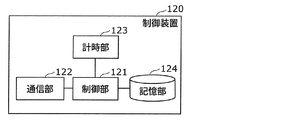
- FIG. 2 is a block diagram showing the functional configuration of the control device.
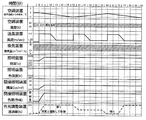
- FIG. 3 is a time chart for explaining the first control in which the function of the sympathetic nerve of the subject is dominant.
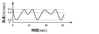
- FIG. 4 is a diagram showing an example of fluctuations in wind speed.
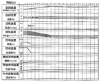
- FIG. 5 is a time chart for explaining the second control in which the function of the parasympathetic nerve of the subject is dominant.
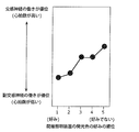
- FIG. 6 is a diagram showing an analysis result of an experiment conducted by the inventors.
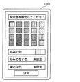
- FIG. 7 is a diagram showing an example of a light emission color setting screen displayed on the setting device.
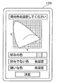
- FIG. 8 is a diagram showing another example of the emission color setting screen displayed on the setting device.
- FIG. 7 is a diagram showing an example of a light emission color setting screen displayed on the setting device.
- FIG. 9 is a diagram showing an example of an irradiation area and irradiation place setting screen displayed on the setting device.
- FIG. 10 is a diagram showing the function of the sympathetic nerve and the function of the parasympathetic nerve.
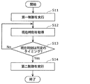
- FIG. 11 is a flowchart of Operation Example 1 of the environment control system according to the embodiment.
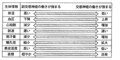
- FIG. 12 is a diagram showing the relationship between the functions of the sympathetic nerve and parasympathetic nerve and changes in biological information.
- FIG. 13 is a diagram for explaining the control based on the heart rate.
- FIG. 14 is a diagram showing the schedule information of the target person and the control switching timing.
- each diagram is a schematic diagram, and is not necessarily an exact illustration. Further, in each drawing, the same reference numerals are given to substantially the same configurations, and overlapping description may be omitted or simplified.
- FIG. 1 is a diagram showing a configuration of an environment control system according to an embodiment.
- the environment control system 10 shown in FIG. 1 controls the target device related to the environment in the space 300, which is a closed space such as a room, to control the function of the autonomic nerve of the target person 200.
- the autonomic nerve contains two types of nerves, the sympathetic nerve and the parasympathetic nerve, which work in contrast, and the functions of human organs are maintained by these two types of nerves working in balance.
- the environmental control system 10 switches the first control that makes the function of the sympathetic nerve dominate the work of the parasympathetic nerve and the second control that makes the work of the parasympathetic nerve dominate the work of the sympathetic nerve at predetermined timings. Thereby, the disturbance of the autonomic nerve of the subject 200 can be suppressed.
- the environment control system 10 includes a blower 20, an air conditioner 30, a lighting device 40, an outside light adjusting device 50, an indirect lighting device 60, a ventilation device 70, a speaker 80, and a scent generation device.
- a device 90, an environment measuring device 100, a biological information measuring device 110, a control device 120, and a setting device 130 are provided.
- the blower device 20 is a device that blows air toward the target person 200.
- the blower 20 is specifically a blower having a relatively high directivity such as a circulator, but may be a fan or the like.
- the position information of the target person 200 is acquired by the sensor, and the wind from the blower device is sent to the target person 200 based on the position information. it can.
- the required air volume can be sent to the target person 200.
- by always acquiring the position information of the target person 200 by the sensor it is possible to send an appropriate air volume following to the target person 200 moving in the room.
- the air conditioner 30 is a device for adjusting the temperature of the space 300 in which the target person 200 is located.
- the air conditioner 30 can also adjust the humidity of the space 300.
- the air conditioner 30 brings the temperature and humidity of the space 300 close to the temperature and humidity instructed by the control device 120.
- the lighting device 40 is a device for direct lighting that illuminates the space 300 in which the target person 200 is located.
- the lighting device 40 is, for example, a ceiling light having a light emitting element such as an LED as a light source, but may be another lighting device such as a base light or a downlight.
- the lighting device 40 can be dimmed and toned by the control device 120.
- the external light adjustment device 50 is a device that adjusts the amount of external light taken into the space 300 in which the target person 200 is located.
- the external light adjusting device 50 is, for example, an electronic blind realized by a light control film or the like, but may be an electric blind (electric shutter).
- the indirect lighting device 60 is a device for indirect lighting arranged in the space 300 in which the target person 200 is located.
- the indirect lighting device 60 is arranged, for example, in a place where the light source (or the entire indirect lighting device 60) cannot be directly seen, and reflects the light on a wall or a ceiling to indirectly illuminate the space 300. That is, the indirect lighting device 60 directly illuminates a structure such as a wall or a ceiling that defines the space 300.
- the indirect lighting device 60 can change the emission color by having a plurality of light sources having different emission colors, for example.
- the indirect lighting device 60 has, for example, a light source that emits red light, a light source that emits green light, and a light source that emits blue light, and changes the emission color by adjusting the brightness of the light emitted by each light source.
- the indirect lighting device 60 may realize an arbitrary emission color by combining a light source and an optical filter.
- a spotlight, a stand light, a bracket light, a pendant light, a line lighting, or the like is used as the indirect lighting device 60.
- the inventors can make the function of the sympathetic nerve of the target person 200 dominant over the function of the parasympathetic nerve by causing the indirect lighting device 60 to emit light with an emission color that the target person 200 does not like. Found. Further, the inventors have found that by causing the indirect lighting device 60 to emit light in the emission color that the subject 200 prefers, the action of the parasympathetic nerve of the subject 200 can be made superior to the action of the sympathetic nerve. .. Control using such an indirect lighting device 60 will be described in detail in the section “[Other control using indirect lighting device]” below.
- the ventilation device 70 ventilates the space 300 in which the target person 200 is located. Unlike the air conditioner 30, the ventilation device 70 does not have a temperature adjusting function.
- the ventilation device 70 is, for example, a total heat exchanger (ERV: Energy Recovery Ventilator), but may be a ventilation device such as a ventilation fan that does not involve heat exchange. Further, the ventilation device 70 may be a window opening/closing device provided in the space 300.
- the speaker 80 is a device that is placed in the space 300 in which the target person 200 is located and outputs voice or music.
- the scent generating device 90 is a device that emits a scent and is arranged in a space where the target person 200 is located.
- the scent generating device 90 is, for example, an aroma diffuser, but may be another scent generating device.
- the environment measuring device 100 is a device that measures environment information in the space 300 in which the target person 200 is located.
- the environment measuring apparatus 100 measures, for example, a temperature sensor that measures the temperature in the space 300, a humidity sensor that measures the humidity in the space 300, an illuminance sensor that measures the illuminance in the space 300, and a carbon dioxide (CO 2 ) concentration in the space 300.
- a CO 2 sensor or the like measures a temperature sensor that measures the temperature in the space 300, a humidity sensor that measures the humidity in the space 300, an illuminance sensor that measures the illuminance in the space 300, and a carbon dioxide (CO 2 ) concentration in the space 300.
- CO 2 carbon dioxide
- the biological information measuring device 110 is a device that measures the biological information of the target person 200.
- the biological information measuring device 110 measures the body temperature, blood pressure, heart rate, pulse wave, sweat rate, pupil diameter, skin temperature, facial expression, etc. of the subject 200 as biological information.
- the biological information measuring device 110 is VLF (Very Low Frequency), HF (High Frequency), LF (Low Frequency), LF/HF, and heartbeat variation coefficient calculated from the heartbeat, pulse wave, and respiratory fluctuation waveform. CVR-R, inspiration time of breathing, evacuation time, pause time, etc. may be measured.
- the biological information measuring device 110 is, for example, a wearable sensor (in other words, a contact sensor) attached to the body of the target person 200, but may be a non-contact sensor. Examples of the non-contact type sensor include a radio wave sensor capable of measuring heart rate, respiration rate, pulse wave and the like, a camera capable of measuring pupil diameter, pulse or facial expression.
- the control device 120 is a device that controls target devices such as the air blower 20, the air conditioner 30, the lighting device 40, the outside light adjusting device 50, the indirect lighting device 60, the ventilation device 70, the speaker 80, and the scent generating device 90. is there.
- FIG. 2 is a block diagram showing a functional configuration of the control device 120.
- the control device 120 includes a control unit 121, a communication unit 122, a clock unit 123, and a storage unit 124.
- the control unit 121 controls the target device by causing the communication unit 122 to transmit a control signal.
- the control unit 121 is realized by, for example, a microcomputer, but may be realized by a processor.
- the communication unit 122 is a communication circuit (in other words, a communication module) for the control device 120 to communicate with the target device.
- the communication unit 122 transmits a control signal to the target device under the control of the control unit 121, for example.
- the communication unit 122 receives the environment information of the space 300 from the environment measurement device 100, and receives the biometric information of the target person 200 from the biometric information measurement device 110.
- the communication unit 122 performs wireless communication, for example, but may perform wired communication.
- the communication standard of communication performed by the communication unit 122 is not particularly limited.
- the clock unit 123 measures the current time.
- the clock unit 123 is realized by, for example, a real-time clock.
- the storage unit 124 is a storage device that stores a control program for the control unit 121 to control the target device.
- the storage unit 124 is realized by, for example, a semiconductor memory.
- the setting device 130 performs an operation of a user such as the target person 200 (for example, a setting operation related to the first control that makes the function of the sympathetic nerve dominant, or a setting operation related to the second control that makes the function of the parasympathetic nerve dominant). It is a user interface device that accepts. The content of the setting accepted by the setting device 130 is transmitted to the control device 120 as setting information.
- the setting device 130 is, for example, a mobile terminal such as a smartphone or a tablet terminal, but may be an operation panel installed on a wall or the like.
- the setting device 130 may be realized as a part of another device.
- the setting device 130 may be realized as an operation reception unit included in the control device 120.
- the operation reception unit is specifically realized by a touch panel, hardware buttons, or the like.
- FIG. 3 is a time chart for explaining the first control that makes the function of the sympathetic nerve of the subject 200 dominant. Note that in FIG. 3, 0 minutes is the start time of the first control, and as an example, it is assumed that the control of the target device is performed only by the comfort time until the start time. In FIG. 3, 0 to 90 minutes are shown, but after 90 minutes, the same control as in 30 to 90 minutes is repeated.
- At least one target device may be controlled, but a plurality of target devices may be controlled.
- the stimulus applied to the subject 200 is strengthened, so that the function of the sympathetic nerve can be made more dominant.
- the air blower 20 is installed at a position where the air can be blown to a part such as an arm, a neck, and a face where the skin of the subject 200 is exposed.
- the blower 20 is installed, for example, so that the wind blows against the face of the target person 200.
- a strong stimulus such as lowering the sensible temperature of the target person 200, and it is possible to lower the oxygen concentration around the face of the target person 200. Therefore, the function of the sympathetic nerve can be made dominant.
- the control unit 121 of the control device 120 changes the wind speed of the air blown by the blower device 20 in a predetermined cycle of 15 minutes or more and 60 minutes or less.
- the control unit 121 sets the time when the wind speed becomes the minimum value to 50% or less of the predetermined cycle. If the wind speed changes with time in this manner, it is possible to constantly apply the wind stimulus to the target person 200 (it becomes difficult for the target person 200 to become accustomed to the wind stimulus), and the fatigue level of the target person 200 is suppressed. Therefore, the state in which the function of the sympathetic nerve is dominant is easily maintained.
- control unit 121 changes the wind speed of the air blown by the air blower 20 in a 30-minute cycle.
- the duration of concentration of human being is about 15 minutes to 60 minutes, and when the wind speed changes in a predetermined cycle of 15 minutes or more and 60 minutes or less (for example, 30 minutes cycle), the target The person 200 can be effectively stimulated.
- the time when the wind speed becomes the minimum value corresponds to 50% of the predetermined cycle, but may be shorter than 50% of the predetermined cycle.
- the wind speed of the air blown by the blower device 20 reaches the maximum value (for example, 4.0 m/sec) immediately after the control is started, and is maintained at the maximum value for 10 minutes. Thereafter, the wind speed linearly decreases over 5 minutes to reach a minimum value (for example, 1.25 m/sec), and is maintained at the minimum value for 15 minutes. That is, the time until the wind speed of the air blown by the blower device 20 changes from the minimum value to the maximum value (for example, almost 0) is the time until the wind speed of the wind blown by the blower device 20 changes from the maximum value to the minimum value. Shorter than (for example, 5 minutes).
- the target person 200 can be effectively stimulated. Further, if the time taken for the wind speed of the air blown by the air blower 20 to change from the maximum value to the minimum value is set to be relatively short, it is possible to prevent the target person 200 from feeling uncomfortable.
- the control unit 121 causes the wind velocity of the air blown by the blower device 20 to fluctuate with respect to the maximum value (for example, 4.0 m/sec) (for example, 5). 0.0 m/sec) to the minimum fluctuation value (for example, 1.0 m/sec). That is, although the wind speed seems to change linearly in FIG. 3, the wind speed actually changes. Hereinafter, such a change in wind speed is also referred to as “fluctuation”.
- FIG. 4 is a diagram showing an example of such fluctuations in wind speed.
- the fluctuation of wind speed is, for example, 1/f fluctuation, but it may be random fluctuation.
- 1/f fluctuation means a fluctuation in which the power spectral density is inversely proportional to the frequency f.
- the fluctuation of the wind speed is formed in a cycle of several seconds order of about 1 sec to 10 sec. That is, the control unit 121 causes the wind speed of the air blown by the air blower to fluctuate at a time interval shorter than a predetermined cycle (30 minutes).
- the subject 200 can be constantly given a wind stimulus (it becomes difficult for the subject 200 to become accustomed to the wind stimulus), so that the sympathetic nerve is dominant. Is easier to maintain. Further, if the fluctuation is not periodic, it is possible to constantly apply the wind stimulation to the target person 200 (it becomes difficult for the target person 200 to become accustomed to the wind stimulation).
- the control unit 121 uses the air conditioner 30 to raise or lower the temperature around the subject 200.
- the control unit 121 lowers the ambient temperature by 3° C. from the reference temperature over 30 minutes at the beginning of the first control in which the function of the sympathetic nerve is dominant, and then increases the ambient temperature by 3° C. over 30 minutes.
- Let The temperature change is preferably within 30 minutes. After that, such temperature change is repeated.
- the reference temperature varies depending on the season, for example, 26° C. in summer, 22° C. in spring and autumn, and 20° C. in winter. Note that it may be better to change the temperature by 3° C. or more in order to make the sympathetic nerve function dominant. Considering health, the temperature change may be within 5° C., and is 3° C. in the example of FIG.
- the temperature around the target person 200 is measured by, for example, the environment measuring device 100, and the control unit 121 controls the air conditioner 30 based on the temperature measured by the environment measuring device 100.
- the controller 121 may increase or decrease the temperature setting of the air conditioner 30 in the 60-minute cycle as described above, without using the environment measuring device 100.
- control unit 121 raises and lowers the temperature in a predetermined cycle (for example, a 60-minute cycle). If the temperature changes with time, a stimulus due to the temperature can be constantly applied to the target person 200 (it becomes difficult for the target person 200 to become accustomed to the stimulus due to the temperature), so that the function of the sympathetic nerve of the target person 200 is superior. The state is easily maintained.
- a predetermined cycle for example, a 60-minute cycle.
- the control unit 121 also adjusts the timing at which the temperature around the target person 200 rises and falls to match the timing at which the wind speed of the air blown by the blower device 20 rises. That is, when the temperature around the target person 200 is switched between rising and falling, the wind speed of the air blown by the blowing device 20 increases. As a result, a temperature change occurs as another stimulus at the timing when the air blower 20 increases the wind speed, that is, at the timing when the stimulus to the target person 200 is intensified, so that the stimulus can be further enhanced. Therefore, the function of the sympathetic nerve of the subject 200 can be made more dominant.
- the control unit 121 controls the humidity of the space 300 to a range of 40% or more and 60% or less by using the air conditioner 30 while the first control that makes the function of the sympathetic nerve dominant is performed.
- the control unit 121 uses the lighting device 40 to illuminate the illuminance of the space 300 when the wind speed of the air blown by the blower device 20 first rises (in other words, at the beginning of the first control in which the function of the sympathetic nerve is predominant). Raise.
- the control unit 121 raises the illuminance of the space 300 to 3000 lux within 5 minutes from the start of control, for example. It is preferable to change the illuminance with time to such an extent that the subject 200 does not have a dislike of the illuminance change.
- control unit 121 raises the color temperature of the light emitted by the lighting device 40 when the wind speed of the air blown by the air blower 20 first rises.
- the color temperature is not changed, but if the color temperature before the control is started is low, the control for increasing the color temperature is performed. It is preferable to change the illuminance over time to such an extent that the subject 200 does not have a dislike of the change in chromaticity.
- the control unit 121 uses the outside light adjusting device 50 to create a space 300. Increases the amount of outside light taken in. Specifically, the control unit 121 increases the light transmittance of the external light adjustment device 50. It is preferable to change the illuminance to such an extent that the subject 200 does not have a dislike for the illuminance change.
- control unit 121 may thereafter control the outside light adjustment device 50 according to the weather.
- the weather is performed based on, for example, the illuminance indicated by an illuminance sensor included in the outside light adjustment device 50.
- the control unit 121 sets the light transmittance of the external light adjusting device 50 to 100% when the weather is cloudy (when the illuminance indicated by the illuminance sensor is relatively low), and when the weather is fine (the illuminance sensor). (When the illuminance is relatively high), the transmittance is reduced to, for example, about 10% for the purpose of suppressing glare.
- the control unit 121 first emits the color of light emitted by the indirect lighting device 60 when the wind velocity of the air blown by the blower device 20 first rises (in other words, at the beginning of the first control in which the function of the sympathetic nerve is predominant). To change. Control unit 121, for example, increased brightness from the start of control at 5 minutes (substantially illuminance) from 0 (colorless) cd / m 2 to 60 cd / m 2. The emission color at this time is, for example, red, but may be orange or the like.
- the control unit 121 determines the chromaticity of the light emitted by the indirect lighting device 60 at the beginning of the first control in which the function of the sympathetic nerve is predominant, with the x coordinate of the chromaticity diagram of the CIE 1931 color space of the chromaticity. You can change it to be larger. Thereby, the function of the sympathetic nerve of the subject 200 can be made dominant.
- control unit 121 may cause the indirect lighting device 60 to emit light in a light emission color that the target person 200 does not prefer in the first control in which the function of the sympathetic nerve is dominant.
- the inventors can make the function of the sympathetic nerve dominate effectively by causing the indirect lighting device 60 to emit light with a light emission color that the subject 200 does not like, compared with the case where other devices such as the blower device 20 are controlled. Found.
- the control of causing the indirect lighting device 60 to emit light with a light emission color that is not the favorite of the target person 200 will be described in detail in the section of [Another control using the indirect lighting device] described later.
- the control unit 121 causes the illuminance of light emitted by the indirect lighting device 60 to fluctuate. That is, the brightness of the light emitted by the indirect lighting device 60 is brightened or darkened in a cycle of a few seconds on the order of 1 sec to 10 sec (which may be a fixed cycle or a random cycle).
- the light emitted by the indirect lighting device 60 may fluctuate with a constant amplitude or may fluctuate with a random amplitude.
- the control unit 121 may change the illuminance of the light emitted by the indirect lighting device 60, like the waveform of the wind speed in FIG.
- the stimulus by the indirect light can be constantly applied to the target person 200 (it becomes difficult for the target person 200 to get accustomed to the stimulus by the indirect light).
- the state in which the sympathetic nerve function is dominant is easily maintained.
- the controller 121 uses the ventilation device 70 to reduce the carbon dioxide concentration in the space 300 to less than 1000 ppm.
- 1000 ppm is an example of a predetermined concentration.
- the control unit 121 increases the ventilation amount of the ventilation device 70 to reduce the carbon dioxide concentration in the space 300 to less than 1000 ppm.
- the carbon dioxide concentration in the space 300 is measured by, for example, the environment measuring device 100, and the control unit 121 controls the ventilation device 70 based on the carbon dioxide concentration measured by the environment measuring device 100.
- the sympathetic function of the target person 200 can be made dominant by lowering the carbon dioxide concentration in the space 300.
- the control unit 121 changes the sound emitted by the speaker 80 when the wind speed of the air blown by the air blower 20 increases.
- “changing the sound” includes starting sound output in a state where no sound is output.
- the speaker 80 outputs, for example, a song having a relatively uptempo.
- the sound changes as another stimulus at the timing when the blowing device 20 increases the wind speed, that is, at the timing when the stimulus to the target person 200 is intensified, so that the stimulus can be further enhanced. Therefore, the function of the sympathetic nerve of the subject 200 can be made more dominant.
- the control unit 121 changes the scent emitted by the scent generation device when the wind speed of the air blown by the blower device 20 increases.
- “changing the scent” includes starting the generation of the scent in the state where the scent is not generated.
- the scent generating device 90 generates a pleasant stimulating scent such as mint scent.
- the scent changes as another stimulus at the timing when the air blower 20 increases the wind speed, that is, at the timing when the stimulus to the target person 200 is intensified, so that the stimulus can be further enhanced. Therefore, the function of the sympathetic nerve of the subject 200 can be made more dominant.
- FIG. 5 is a time chart for explaining the control in which the function of the parasympathetic nerve of the subject 200 is made dominant. Note that in FIG. 5, the time 0 minutes is the start time of the second control, and as an example, it is assumed that the control of the target device is performed by considering only the comfort until the start time. In FIG. 5, 0 to 90 minutes are shown, but after 90 minutes, the same control as in 30 to 90 minutes is repeated.
- At least one target device may be controlled, but a plurality of target devices may be controlled. Thereby, the function of the parasympathetic nerve can be more dominant.
- the control unit 121 of the control device 120 raises the temperature of the space 300 by using the air conditioner 30 at the beginning of the second control in which the function of the parasympathetic nerve is predominant. Specifically, the control unit 121 raises the ambient temperature by 3° C. from the reference temperature over 30 minutes immediately after the control is started.
- the time (30 minutes) required to raise the temperature is an example and is not particularly limited. It is desirable to raise the ambient temperature by about 3° C. over 30 minutes.
- the reference temperature varies depending on the season, for example, a predetermined temperature of 25°C or higher and 27°C or lower in summer, a predetermined temperature of 21°C or higher and 23°C or lower in spring and autumn, and a predetermined temperature of 17°C or higher and 20°C or lower in winter. Is the temperature.
- the control unit 121 lowers the ambient temperature by 1° C. over 30 minutes and then raises the ambient temperature by 1° C. over 30 minutes. After that, such temperature change is repeated. That is, the control unit 121 uses the air conditioner 30 to periodically change the temperature of the space 300 such that the width from the maximum value to the minimum value is less than 3°C.
- the ambient temperature of the target person 200 is measured by, for example, the environment measuring device 100, and the control unit 121 controls the air conditioner 30 based on the temperature measured by the environment measuring device 100.
- the controller 121 may increase or decrease the temperature setting of the air conditioner 30 in the 60-minute cycle as described above, without using the environment measuring device 100.
- the cycle of changing the temperature (60 minutes) is an example, and is not particularly limited.
- control unit 121 slightly raises and lowers the temperature (specifically, about 3° C. or less) in a predetermined cycle (for example, a 60-minute cycle).
- a predetermined cycle for example, a 60-minute cycle.
- a body heats up a person sweats and cools the body, and over time, the body heats up repeatedly, which causes repeated basal metabolism. If the temperature of the subject 200 is kept constant, this basal metabolism will be ignored, and it will be felt that it is too hot or too cold.
- the function of the parasympathetic nerve of the subject 200 can be made dominant.
- the control unit 121 controls the humidity of the space 300 to a range of 40% or more and 60% or less by using the air conditioner 30 while the second control in which the function of the parasympathetic nerve is predominant is performed.
- the controller 121 uses the ventilation device 70 to set the carbon dioxide concentration in the space 300 to 1000 ppm or more. For example, when the carbon dioxide concentration in the space 300 is low, the control unit 121 reduces the ventilation amount of the ventilation device 70 to set the carbon dioxide concentration in the space 300 to 1000 ppm or more. 1000 ppm is an example of a predetermined concentration. The controller 121 may stop the ventilation device 70 to increase the carbon dioxide concentration in the space 300 to 1000 ppm or more. The carbon dioxide concentration in the space 300 is measured by, for example, the environment measuring device 100, and the control unit 121 controls the ventilation device 70 based on the carbon dioxide concentration measured by the environment measuring device 100.
- the function of the parasympathetic nerve of the subject 200 can be made dominant.
- the control unit 121 stops the air blow by the air blower 20 in the second control in which the function of the parasympathetic nerve is predominant.
- the blower 20 remains stopped before the control starts, but when the blower 20 is operating before the start of the control, the blower 20 is stopped.
- the stimulation given to the target person 200 by the wind blown by the blower 20 is reduced, so that the function of the parasympathetic nerve can be made dominant.
- control for weakening the wind speed may be performed as compared to before the control is started, and such control can also predominantly function the parasympathetic nerve. ..
- the control unit 121 reduces the illuminance of the space 300 by using the lighting device 40 at the beginning of the control in which the function of the parasympathetic nerve is dominant.
- the control unit 121 reduces the illuminance of the space 300, which was initially 750 lux, to 750 lux within 5 minutes from the start of control. It is preferable to change the illuminance with time to such an extent that the subject 200 does not have a dislike of the illuminance change.
- the term "decreasing the illuminance of the lighting device 40 in the space 300" here includes turning off the lighting device 40.
- the light stimulus given to the target person 200 is weakened by making the space 300 dark, so that the function of the parasympathetic nerve of the target person 200 can be made dominant.
- control unit 121 lowers the color temperature of the light emitted by the lighting device 40 at the beginning of the second control in which the function of the parasympathetic nerve is predominant. It is preferable to change the chromaticity over time so that the subject 200 does not have a dislike of the chromaticity change.
- the color temperature of the light emitted from the illumination device 40 which was initially 5000K, is lowered to 2500K.
- the function of the parasympathetic nerve of the target person 200 can be made dominant by setting the lighting environment with a low color temperature in the space 300.
- the control unit 121 reduces the amount of external light taken into the space 300 by using the external light adjusting device 50 at the beginning of the second control in which the function of the parasympathetic nerve is predominant.
- the control unit 121 specifically lowers the light transmittance of the external light adjustment device 50. It is preferable to change the illuminance with time to such an extent that the subject 200 does not have a dislike of the illuminance change.
- the term “decreasing the light transmittance of the external light adjusting device 50” here includes setting the transmittance of the external light adjusting device 50 to 0% and blocking the light.
- the light stimulus given to the target person 200 is weakened by making the space 300 dark, so that the function of the parasympathetic nerve of the target person 200 can be made dominant.
- the control unit 121 changes the emission color of the light emitted by the indirect lighting device 60 in the second control in which the function of the parasympathetic nerve is predominant.
- Control unit 121 for example, increased brightness from the start of control at 5 minutes (substantially illuminance) from 0 (colorless) cd / m 2 to 10 cd / m 2.
- the emission color at this time is, for example, blue, but may be emerald green or the like.
- the control unit 121 determines the chromaticity of light emitted by the indirect lighting device 60 at the x-coordinate of the chromaticity diagram of the CIE 1931 color space of the chromaticity at the beginning of the second control in which the function of the parasympathetic nerve is dominant. Change it so that it becomes smaller. Thereby, the function of the parasympathetic nerve of the subject 200 can be made dominant.
- control unit 121 may cause the indirect lighting device 60 to emit light in the emission color that the subject 200 prefers in the second control in which the function of the parasympathetic nerve is dominant.
- the inventors can make the function of the parasympathetic nerve dominate by effectively causing the indirect lighting device 60 to emit light with the emission color that the subject 200 prefers, compared to the case where another device such as the blower device 20 is controlled. Found.
- the control of causing the indirect lighting device 60 to emit light with the emission color that the target person 200 prefers will be described in detail in the section [Another control using the indirect lighting device] described later.
- the control unit 121 causes the illuminance of light emitted by the indirect lighting device 60 to fluctuate. That is, the brightness of the light emitted by the indirect lighting device 60 is brightened or darkened in a cycle of a few seconds on the order of 1 sec to 10 sec (which may be a fixed cycle or a random cycle).
- the light emitted by the indirect lighting device 60 may fluctuate with a constant amplitude or may fluctuate with a random amplitude.
- the control unit 121 may change the illuminance of the light emitted by the indirect lighting device 60, like the waveform of the wind speed in FIG. Thereby, the function of the parasympathetic nerve of the subject 200 can be made dominant.
- the control unit 121 changes the sound emitted by the speaker 80 in the second control in which the function of the parasympathetic nerve is dominant.
- “changing the sound” includes starting sound output in a state where no sound is output.
- the speaker 80 outputs, for example, a sound having a relaxing effect such as healing music, or a song having a relatively slow tempo. Thereby, the function of the parasympathetic nerve of the subject 200 can be made dominant.
- control unit 121 changes the scent emitted by the scent generating device in the second control in which the function of the parasympathetic nerve is dominant.
- “changing the scent” includes starting the generation of the scent in the state where the scent is not generated.
- the scent generating device 90 generates, for example, a scent that contains phytoncide or the like and is not irritating or a lavender scent. Thereby, the function of the parasympathetic nerve of the subject 200 can be made dominant.
- FIG. 6 is a diagram showing an analysis result of an experiment conducted by the inventors.
- the target person 200 ranked the likes and dislikes of the five emission colors while watching the indirect lighting device 60 that actually emitted the five emission colors of red, yellow, white, green, and blue. It was
- the subject 200 was made to stay in the controlled space 300 in an environment in which a plurality of environmental parameters including the emission color of the indirect lighting device 60 were combined, and the heart rate of the subject 200 was measured.
- the heart rate can be used as an index indicating the function of the autonomic nerve. The greater the heart rate, the more dominant the sympathetic function, and the smaller the heart rate, the more dominant the parasympathetic function. Is.
- the plurality of environmental parameters include the speed of air blown, temperature, carbon dioxide concentration, illuminance of light emitted by the lighting device 40, color temperature of light emitted by the lighting device 40, and odor. It includes environmental parameters such as sound.
- the subject 200 was allowed to stay and the heart rate of the subject 200 was measured in each of about 20 environments with different combinations of a plurality of environment parameters.
- the rank of the luminescent color preference of the indirect lighting device 60 of the subject is strongly associated with the function of the autonomic nerve among a plurality of parameters. I found out that there is. Specifically, when the indirect lighting device 60 is made to emit light in a color that the subject prefers, the function of the parasympathetic nerve becomes dominant (that is, the heart rate decreases), and the indirect lighting device 60 becomes a color that the subject does not like. It was found that when the light was emitted, the sympathetic nerve function became dominant (that is, the heart rate was increased).
- the contribution of the luminescent color of the indirect lighting device 60 to the favorite heart rate was 33.96%, which was relatively high among the plurality of environmental parameters used in the experiment.
- the P value indicating significance is 0.042, and it can be said that the preference of the emission color of the indirect lighting device 60 significantly affects the function of the autonomic nerve (that is, the heart rate).
- control unit 121 causes the indirect lighting device 60 to emit a light emission color that the target person 200 does not like in the first control, and causes the indirect lighting device 60 to emit light that the target person 200 likes in the second control. You may make it light-emit with a color.
- the setting device 130 accepts in advance, by the target person 200, the setting of the luminescent color which the target person 200 does not like and the luminescent color of his preference.
- FIG. 7 is a diagram showing an example of a light emission color setting screen displayed on the setting device 130.
- the setting screen displays multiple emission color candidates.
- the target person 200 can set a favorite emission color and a non-preferred emission color from the candidates.
- the target person 200 can also set a disliked emission color.
- the emission color set to the disliked emission color is excluded from the emission colors of the indirect lighting device 60.
- At least the desired emission color should be set. If a desired emission color is set, other emission colors can be treated as non-favorable emission colors.
- a plurality of favorite emission colors and a plurality of non-preferred emission colors may be set. Further, a favorite emission color and a non-preferred emission color may be set for each unit such as time zone, weekday/holiday, or season.
- the setting screen in Fig. 7 is an example.
- the emission color candidates may be displayed as a color palette.
- the chromaticity diagram of the CIE 1931 color space may be displayed on the setting screen, and the emission color may be set by the target person 200 designating the coordinates.
- FIG. 8 is a diagram showing another example of such an emission color setting screen. Further, in setting the emission color, not only the hue but also at least one of the lightness and the saturation may be set in addition to the hue.
- the ratio of green (plant) to the visual field of a person is called the green visual acuity, and it is known that if the green visual acuity is 10% or more, the stress of the person is reduced.
- the function of the autonomic nerve can be adjusted more effectively if the irradiation area is 10% or more of the area within the field of view of the target person 200.
- the irradiation area of the indirect lighting device 60 may be set by the target person 200 via the setting device 130.
- the setting device 130 receives the setting of the irradiation area of the light emitted by the indirect lighting device 60, and the control device 120 sets the irradiation area of the light emitted by the indirect lighting device 60 in each of the first control and the second control.
- the irradiation area is controlled by the setting device 130.
- FIG. 9 is a diagram showing an example of a setting screen of the irradiation area and the irradiation place.
- the target person 200 can set the irradiation area by dragging the slide bar, for example.
- the control unit 121 changes the number of light sources to be emitted from a plurality of light sources included in the indirect lighting device 60, or changes the brightness of light emitted by the light source included in the indirect lighting device 60 to perform irradiation.
- the area can be changed.
- the control unit 121 may change the irradiation area by changing the number of the indirect lighting devices 60 that emit light among the plurality of indirect lighting devices 60. it can.
- the target person 200 can set the irradiation location of the light emitted by the indirect lighting device 60 from the setting screen of FIG.
- the target person 200 can set whether to illuminate the ceiling, the wall, or the floor with the indirect illumination device 60, for example.
- the indirect illumination device 60 has a configuration capable of changing the emission direction of light.
- the control device 120 May cause the indirect lighting device 60 to emit light in the selected emission color.
- the temporary setting state until the setting is fixed may be reflected in the indirect lighting device 60 in real time.
- a temporary setting state until the setting is fixed may be reflected in the indirect lighting device 60 in real time.
- “reflected in real time” means that the operation on the setting device 130 and the light emission mode of the indirect lighting device 60 are substantially synchronized.
- a pattern may be projected on an object (wall, ceiling, floor, or the like) irradiated with the light by the light emitted from the indirect lighting device 60.
- the pattern here is, for example, a striped pattern, a dot pattern, a leaf pattern of a plant, or a cloud pattern floating in the sky. These patterns may change over time.
- an optical system capable of projecting a pattern similar to that of a projector or the like is applied to the indirect illumination device 60. What kind of pattern is displayed is set by the target person 200 via the setting device 130, for example.
- changing the emission color of the indirect lighting device 60 is almost the same as changing the color of the wall of the space 300 in which the target person 200 is located. Therefore, when the wallpaper is realized by a thin display or the like and the color or pattern of the wallpaper itself can be changed, the control unit 121 may control the wallpaper instead of the indirect lighting device 60. When the wallpaper is controlled, the same effect as when the indirect lighting device 60 is controlled is obtained. However, in order to easily change the color of a large area wall or ceiling, it is preferable to use indirect illumination.
- the control unit 121 changes the illuminance of the light emitted by the indirect lighting device 60.
- the manner in which the illuminance of light fluctuates as described above is not particularly limited.
- FIG. 10 is a diagram showing the function of the sympathetic nerve and the function of the parasympathetic nerve. In other words, it can be said that the first time zone in which the sympathetic nerve should be dominant and the second time zone in which the parasympathetic nerve should be dominant are determined to some extent.
- FIG. 11 is a flowchart of such an operation example 1. Note that the operation example 1 shown in FIG. 11 is an example in which the first control is switched to the second control during execution, but the same is true when the second control is switched to the first control during execution.
- the control unit 121 acquires the current time measured by the time measuring unit 123 (S12) during execution of the first control that makes the sympathetic nerve dominant (S11), and whether the acquired current time is a predetermined timing. It is determined whether or not (S13).
- the predetermined timing is, for example, 8:00 PM and is set in advance, but may be set by the setting operation of the target person 200 received by the setting device 130.
- control unit 121 determines that the current time is the predetermined timing (Yes in S13)
- the control unit 121 executes the second control that makes the function of the parasympathetic nerve dominant (S14). If the control unit 121 determines that the current time is not the predetermined timing (No in S13), the control unit 121 continues to acquire the current time (S12) and determine whether the current time is the predetermined timing (S12). S13).
- the environment control system 10 acquires the current time information and switches the first control and the second control at a predetermined timing based on the acquired current time information.
- Such an environment control system 10 can execute each of the first control and the second control in a time zone in which the control should be executed. That is, the environment control system 10 can suppress the disturbance of the autonomic nerve of the target person 200.
- the control device 120 may acquire the biological information of the target person 200 and switch the first control and the second control at a predetermined timing based on the acquired biological information.
- the biological information is measured by the biological information measuring device 110.
- FIG. 12 is a diagram showing the relationship between the functions of the sympathetic nerve and parasympathetic nerve and changes in biological information.
- the biological information such as the body temperature, blood pressure, heart rate, pulse wave, sweat rate, pupil diameter, epidermal temperature, and facial expression of the subject 200 indicates the function of the sympathetic nerve and the function of the parasympathetic nerve. It is related and can be used as an index for switching between the first control and the second control.
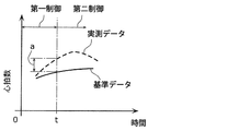
- FIG. 13 is a diagram for explaining the switching timing of control based on the heart rate.
- FIG. 13 is a diagram for explaining the timing for switching the first control to the second control during execution of the first control.
- the changes in the heart rate of the subject 200 at rest for one day are acquired for a plurality of days, and the change in the heart rate for one day obtained by averaging the changes is stored as reference data of the heart rate. ..
- the reference data is shown by a solid line in FIG. Although such reference data is optimized for the target person 200, absolute reference data applied to any person may be used instead of the reference data.
- the control unit 121 monitors the heart rate of the target person 200 measured by the biological information measuring device 110 and compares it with the reference data stored in the storage unit 124. When the heart rate is lower than the reference data, it is presumed that the function of the sympathetic nerve is weak, and it is considered necessary to perform the first control to make the sympathetic nerve dominant. Further, when the heart rate is higher than the reference data, it is estimated that the function of the parasympathetic nerve is weak, and it is considered necessary to control the parasympathetic nerve to have a dominant function.
- the control unit 121 sets the time t when the heart rate measured by the biological information measuring device 110 is larger than the reference data by the threshold value a (a>0) at a predetermined timing. As a result, the first control is switched to the second control. Although not shown, the control unit 121 uses the time when the heart rate measured by the biological information measuring device 110 becomes smaller than the reference data by the threshold value a during the second control as the predetermined timing. The control may be switched to the first control.
- the environmental control system 10 as described above can execute the second control in which the function of the parasympathetic nerve is dominant when the function of the parasympathetic nerve of the subject 200 is estimated to be weaker than usual.
- the environment control system 10 can execute the first control in which the function of the sympathetic nerve is dominant when the function of the sympathetic nerve of the subject 200 is estimated to be weaker than usual. That is, the environment control system 10 can suppress the disturbance of the autonomic nerve of the target person 200.
- the same operation can be performed using biometric information other than the heart rate.
- the control device 120 may acquire the schedule information of the target person 200 and switch the first control and the second control at a predetermined timing based on the acquired schedule information.
- FIG. 14 is a diagram showing schedule information of the target person 200 and control switching timing.
- the schedule information is stored in advance in the storage unit 124, for example, when the setting device 130 receives a schedule input operation of a user such as the target person 200.
- the target person 200 can obtain a good sense of tension and a relaxed feeling at the time of presentation, and can exhibit high performance.
- the control unit 121 executes the first control for the first 30 minutes and executes the second control after the lapse of 30 minutes.
- the target person 200 can obtain a good sense of tension and a relaxed feeling at the time of presentation, and can exhibit high performance.
- the timing at which the first control and the second control are switched may be changed, for example, according to the biological information measured by the biological information measuring device 110. For example, an operation example is conceivable in which the first control is executed until the heart rate of the subject reaches a predetermined value, and then the first control is switched to the second control. For actions other than the presentation, the first control and the second control suitable for the action may be switched before the action.
- the control device 120 controls the chromaticity of the light emitted by the indirect lighting device 60 such that at least one of the x coordinate and the y coordinate of the chromaticity diagram of the CIE 1931 color space of the chromaticity is the first control and the chromaticity.
- the second control may be changed to be different from each other. That is, the control device 120 may change the chromaticity of the light emitted by the indirect lighting device 60 so as to be different between the first control and the second control.
- the environment control system 10 includes the indirect lighting device 60, which is arranged in the space 300 in which the target person 200 is located, and whose emission color can be changed, the favorite color of the target person 200, and the target.
- the setting device 130 that receives the setting of the luminescent color that the person 200 does not like and the indirect lighting device 60 emits the luminescent color that is not the favorite of the subject 200 that is received by the setting device 130, so that the function of the sympathetic nerve of the subject 200 is performed. Sympathy the function of the parasympathetic nerve of the target person 200 by making the indirect lighting device 60 emit light with the luminescent color of the target person 200's favorite received by the setting device 130.
- the control device 120 is provided for switching the second control, which is superior to the function of the nerve, at a predetermined timing.
- Such an environment control system 10 can switch between the first control and the second control by changing the emission color of the indirect lighting device 60.
- the environment control system 10 can suppress the disturbance of the autonomic nerve of the target person 200 by switching the first control and the second control at a predetermined timing.
- the present invention may be realized as an environment control system that performs at least one of such first control and second control.
- the irradiation area of the light emitted by the indirect lighting device 60 is 10% or more of the area within the field of view of the target person 200.
- Such an environment control system 10 can effectively suppress the disturbance of the autonomic nerve of the subject 200.
- the control device 120 causes the indirect lighting device 60 to emit the selected emission color.
- the target person 200 can easily set his/her favorite luminescent color.
- light emitted from the indirect lighting device 60 causes a pattern to be projected on an object irradiated with the light.
- Such an environment control system 10 can project a pattern on an irradiation target by the light emitted from the indirect lighting device 60.
- control device 120 causes the light emitted by the indirect lighting device 60 to fluctuate in each of the first control and the second control.
- the environment control system 10 as described above can realize the first control and the second control that cause the light emitted by the indirect lighting device 60 to fluctuate.
- the environment control system 10 further includes an environment measuring device 100 that measures environment information in the space 300 in which the target person 200 is located.
- the control device 120 switches the first control and the second control at the predetermined timing based on the measured environmental information.
- the environment measuring device 100 is an example of a measuring device.
- Such an environment control system 10 can execute each of the first control and the second control based on the environment information in the space 300.
- control device 120 acquires the current time information and switches the first control and the second control at a predetermined timing based on the acquired current time information.
- Such an environment control system 10 can execute each of the first control and the second control in a time zone in which the control should be performed. That is, the environment control system 10 can suppress the disturbance of the autonomic nerve of the target person 200.
- control device 120 acquires the biological information of the target person 200, and switches the first control and the second control at a predetermined timing based on the acquired biological information.
- Such an environment control system 10 executes the first control based on the biological information when the function of the sympathetic nerve of the target person 200 is estimated to be weaker than usual, so that the function of the parasympathetic nerve of the target person 200 is controlled.
- the second control can be executed when it is estimated to be weaker than usual. That is, the environment control system 10 can suppress the disturbance of the autonomic nerve of the target person 200.
- control device 120 acquires the schedule information of the target person 200, and switches the first control and the second control at a predetermined timing based on the acquired schedule information.
- the environment control system 10 as described above can make the target person 200 exhibit high performance by switching between the first control and the second control suitable for the action defined in the schedule information.
- the environment control method executed by a computer such as the environment control system 10 accepts the setting of the luminescent color that the target person 200 prefers and the luminescent color that the target person 200 does not like, and sets the space in which the target person 200 is located.
- the arranged indirect lighting device 60 capable of changing the luminescent color is made to emit light with a luminescent color which is not preferred by the received target person 200 so that the function of the sympathetic nerve of the target person 200 becomes superior to the function of the parasympathetic nerve.
- the first control and the second control that makes the function of the parasympathetic nerve of the subject 200 more dominant than the function of the sympathetic nerve by emitting light with the received emission color of the subject 200 that has been accepted are switched at a predetermined timing.
- the first control and the second control can be switched by changing the emission color of the indirect lighting device 60.
- the environment control method can suppress disturbance of the autonomic nerve of the target person 200 by switching the first control and the second control at a predetermined timing.
- the environmental control system 10 changes the sympathetic nerve of the target person 200 by changing the wind speed of the air blower 20 that sends the wind toward the target person 200 and the speed of the wind sent by the blower device 20 in a predetermined cycle.
- the first control that makes the work superior to the work of the parasympathetic nerve, and the wind speed of the air blown by the blower device 20 is made smaller than that of the first control so that the work of the parasympathetic nerve of the target person 200 is made more than the work of the sympathetic nerve.
- a control device 120 that switches the second control, which is also superior, at a predetermined timing.
- Such an environment control system 10 can switch the first control and the second control by changing the control content of the blower 20.
- the environment control system 10 can suppress the disturbance of the autonomic nerve of the target person 200 by switching the first control and the second control at a predetermined timing.
- the predetermined cycle is a cycle of 15 minutes or more and 60 minutes or less, and the time when the wind speed becomes the minimum value in the first control is 50% or less of the predetermined cycle.
- the environment control system 10 as described above can constantly apply the wind stimulus to the target person 200 by changing the wind speed with time in the first control. Since it becomes difficult for the subject 200 to get used to the stimulation by the wind, the state in which the function of the sympathetic nerve is predominant is easily maintained.
- control device 120 causes the wind speed of the air blown by the blower device 20 to fluctuate at a time interval shorter than a predetermined cycle.
- Such an environment control system 10 can constantly apply a wind stimulus to the target person 200 by changing the wind speed with time. Since it becomes difficult for the subject 200 to get used to the stimulation by the wind, the state in which the function of the sympathetic nerve is dominant is easily maintained.
- the environment control system 10 further includes an air conditioner 30 for adjusting the temperature of the space where the target person 200 is located.
- the control device 120 uses the air conditioner 30 to periodically change the temperature of the space 300 so that the width from the maximum value to the minimum value becomes equal to or more than a predetermined value (for example, 3° C.).
- a predetermined value for example, 3° C.
- the control device 120 uses the air conditioner 30 to periodically change the temperature of the space 300 such that the width from the maximum value to the minimum value is less than a predetermined value (for example, 1° C.).
- the predetermined value is, for example, a value larger than 1° C. and smaller than 3° C.
- Such an environment control system 10 can realize the first control and the second control by changing the control content of the air conditioner 30.
- control device 120 lowers the temperature of the space by using the air conditioner 30 at the beginning of the first control, and raises the temperature of the space 300 by using the air conditioner 30 at the beginning of the second control.
- Such an environment control system 10 can realize the first control and the second control by changing the control contents of the air conditioner 30 at the beginning of the control.
- the environment control system 10 further includes a lighting device 40 that illuminates the space 300 in which the target person 200 is located.
- the control device 120 increases the illuminance of the space 300 using the lighting device 40 at the beginning of the first control, and reduces the illuminance of the space 300 using the lighting device 40 at the beginning of the second control.
- the environment control system 10 as described above can realize the first control and the second control by changing the control content regarding the illuminance of the lighting device 40.
- the environment control system 10 further includes a lighting device 40 that illuminates the space 300 in which the target person 200 is located.
- the control device 120 raises the color temperature of the light emitted by the lighting device 40 at the beginning of the first control, and lowers the color temperature of the light emitted by the lighting device 40 at the beginning of the second control.
- the environment control system 10 as described above can realize the first control and the second control by changing the control content regarding the color temperature of the lighting device 40.
- the environment control system 10 further includes an indirect lighting device 60 arranged in the space 300 in which the target person 200 is located.
- the chromaticity of the light emitted by the indirect lighting device 60 is changed so that at least one of the x coordinate and the y coordinate of the chromaticity diagram of the CIE 1931 color space of the chromaticity is different between the first control and the second control.
- the environment control system 10 as described above can realize the first control and the second control by changing the control content regarding the chromaticity of the indirect lighting device 60.
- the environmental control system 10 further includes a ventilation device 70 that ventilates the space 300 in which the target person 200 is located.
- the control device 120 uses the ventilation device 70 to reduce the carbon dioxide concentration in the space 300 below a predetermined concentration in the first control, and uses the ventilation device 70 to increase the carbon dioxide concentration in the space 300 to a predetermined concentration or higher in the second control.
- the predetermined concentration is, for example, 1000 ppm.
- Such an environment control system 10 can realize the first control and the second control by changing the control content of the ventilation device 70.
- the environment control system 10 further includes a speaker 80 and a scent generating device 90 arranged in the space 300 in which the target person 200 is located.
- the control device 120 causes the sound output from the speaker 80 to differ between the first control and the second control, and causes the scent generated by the scent generating device 90 to differ between the first control and the second control.
- the control device 120 causes the speaker 80 to output a song with an uptempo in the first control, and causes the speaker 80 to output a sound having a relaxing effect such as healing music or a song with a slow tempo in the second control.
- the control device 120 causes the scent generating device 90 to generate a mint scent in the first control, and the second controlling causes the scent generating device 90 to contain phytoncide or the like with little stimulus, or a lavender scent. Generate.
- Such an environment control system 10 can realize the first control and the second control by changing the control contents of the speaker 80 and the scent generating device 90.
- an environment control method executed by a computer such as the environment control system 10 is performed by changing the wind speed of the wind sent by the blower device 20 that sends the wind toward the target person 200 in a predetermined cycle.
- the second control which is superior to the function of the sympathetic nerve, is switched at a predetermined timing.
- the first control and the second control can be switched by changing the control content of the blower device 20.
- the environment control method can suppress disturbance of the autonomic nerve of the target person 200 by switching the first control and the second control at a predetermined timing.
- the processing executed by a specific processing unit may be executed by another processing unit.
- the order of the plurality of processes may be changed, or the plurality of processes may be executed in parallel.
- each component may be realized by executing a software program suitable for each component.
- Each component may be realized by a program execution unit such as a CPU or a processor reading and executing a software program recorded in a recording medium such as a hard disk or a semiconductor memory.
- each component may be realized by hardware.
- Each component may be a circuit (or integrated circuit). These circuits may form one circuit as a whole or may be separate circuits. Further, each of these circuits may be a general-purpose circuit or a dedicated circuit.
- a recording medium such as a system, a device, a method, an integrated circuit, a computer program, or a computer-readable CD-ROM.
- the system, the device, the method, the integrated circuit, the computer program, and the recording medium may be implemented in any combination.
- the present invention may be implemented as an environment control method, a program for causing a computer to execute the environment control method, or a computer-readable non-transitory non-temporary program in which such a program is recorded. May be realized as a general recording medium.
- the present invention may be realized as the control device of the above-described embodiment, or may be realized as a program executed by the computer for operating the computer as such a control device. Further, the present invention may be realized as a computer-readable non-transitory recording medium in which such a program is recorded.
- the environment control system is realized by a plurality of devices. It may be realized as a single device.
- the components included in the environment control system described in the above embodiments may be distributed to the plurality of devices in any way.
- Environmental control system 60 Indirect lighting device 100
Landscapes
- Health & Medical Sciences (AREA)
- Anesthesiology (AREA)
- Heart & Thoracic Surgery (AREA)
- Hematology (AREA)
- Acoustics & Sound (AREA)
- Psychology (AREA)
- Engineering & Computer Science (AREA)
- Biomedical Technology (AREA)
- Veterinary Medicine (AREA)
- Physics & Mathematics (AREA)
- Life Sciences & Earth Sciences (AREA)
- Animal Behavior & Ethology (AREA)
- General Health & Medical Sciences (AREA)
- Public Health (AREA)
- Pain & Pain Management (AREA)
- Circuit Arrangement For Electric Light Sources In General (AREA)
Abstract
Description
[環境制御システムの構成]
まず、実施の形態に係る環境制御システムの構成について説明する。図1は、実施の形態に係る環境制御システムの構成を示す図である。
上述のように、環境制御システム10は、対象者200の交感神経の働きを優位にする第一制御を行うことができる。以下、このような第一制御の詳細について説明する。図3は、対象者200の交感神経の働きを優位にする第一制御を説明するためのタイムチャートである。なお、図3は、時間0分が第一制御の開始時刻であり、一例として開始時刻までは快適性のみを考慮した対象装置の制御が行われているものとする。図3では、0分~90分までが図示されているが、90分以降については、30分~90分と同様の制御が繰り返される。
以下、他の対象装置の制御について引き続き図3を参照しながら説明する。
上述のように、環境制御システム10は、対象者200の副交感神経の働きを優位にする第二制御を行うことができる。以下、このような第二制御の詳細について説明する。図5は、対象者200の副交感神経の働きを優位にする制御を説明するためのタイムチャートである。なお、図5は、時間0分が第二制御の開始時刻であり、一例として開始時刻までは快適性のみを考慮した対象装置の制御が行われているものとする。図5では、0分~90分までが図示されているが、90分以降については、30分~90分と同様の制御が繰り返される。
次に、換気装置70の制御について説明する。制御部121は、換気装置70を用いて空間300における二酸化炭素濃度を1000ppm以上にする。制御部121は、例えば、空間300における二酸化炭素濃度が低いときに、換気装置70の換気量を低下させることにより、空間300における二酸化炭素濃度を1000ppm以上にする。1000ppmは、所定の濃度の一例である。制御部121は、換気装置70を停止させることにより、空間300における二酸化炭素濃度を1000ppm以上にしてもよい。なお、空間300の二酸化炭素濃度は、例えば、環境計測装置100によって計測され、制御部121は環境計測装置100によって計測された二酸化炭素濃度に基づいて換気装置70を制御する。
以下、他の対象装置の制御について引き続き図5を参照しながら説明する。
以下、間接照明装置60を用いた別の制御について説明する。発明者らは対象者200の好みの発光色、及び、対象者200の好みでない発光色で間接照明装置60を発光させることにより、交感神経の働きおよび副交感神経の働きを調整することが可能であることを見出した。図6は、発明者らが行った実験の解析結果を示す図である。
設定装置130は、あらかじめ対象者200によって対象者200の好みでない発光色、及び、好みの発光色の設定を受け付ける。図7は、設定装置130に表示される発光色の設定画面の一例を示す図である。
間接照明装置60が発する光により、当該光の照射対象物(壁、天井、または、床など)に模様が映し出されてもよい。ここでの模様は、例えば、ストライプ模様、ドット模様、植物の葉の模様、または、空に浮かぶ雲の模様などである。これらの模様は、経時的に変化してもよい。なお、この場合、間接照明装置60には、プロジェクタなどと同様の模様を投影可能な光学系が適用される。どのような模様が映し出されるかは、例えば、対象者200によって設定装置130を介して設定される。
一般に、人の自律神経は、昼間は交感神経の働きが副交感神経の働きよりも優位になり、夜間は交感神経の働きが副交感神経の働きよりも優位になる。図10は、交感神経の働きと副交感神経の働きとを示す図である。つまり、交感神経を優位にすべき第一時間帯、副交感神経の働きを優位にすべき第二時間帯は、ある程度決まっているといえる。
制御装置120は、対象者200の生体情報を取得し、取得した生体情報に基づいて第一制御及び第二制御を所定のタイミングで切り替えてもよい。生体情報は、生体情報計測装置110によって計測される。図12は、交感神経及び副交感神経の働きと生体情報の変化の関係を示す図である。図12に示されるように、対象者200の体温、血圧、心拍数、脈波、発汗量、瞳孔径、表皮温度、及び、表情などの生体情報は、交感神経の働き及び副交感神経の働きと関連しており、第一制御及び第二制御を切り替えるための指標として利用できる。
制御装置120は、対象者200のスケジュール情報を取得し、取得したスケジュール情報に基づいて第一制御及び第二制御を所定のタイミングで切り替えてもよい。図14は、対象者200のスケジュール情報と制御の切り替えタイミングとを示す図である。なお、スケジュール情報は、例えば、設定装置130が対象者200などのユーザのスケジュールの入力操作を受け付けることにより、記憶部124にあらかじめ記憶される。
間接照明装置60に関して、制御装置120は、間接照明装置60が出射する光の色度を、当該色度のCIE 1931色空間の色度図のx座標及びy座標の少なくとも一方が第一制御及び第二制御で互いに異なるように変更してもよい。つまり、制御装置120は、間接照明装置60が出射する光の色度を第一制御及び第二制御で互いに異なるように変更してもよい。
以上説明したように、環境制御システム10は、対象者200が位置する空間300に配置された、発光色の変更が可能な間接照明装置60と、対象者200の好みの発光色、及び、対象者200の好みでない発光色の設定を受け付ける設定装置130と、間接照明装置60を設定装置130によって受け付けられた対象者200の好みでない発光色で発光させることにより対象者200の交感神経の働きを副交感神経の働きよりも優位にする第一制御、及び、間接照明装置60を設定装置130によって受け付けられた対象者200の好みの発光色で発光させることにより対象者200の副交感神経の働きを交感神経の働きよりも優位にする第二制御を所定のタイミングで切り替える制御装置120とを備える。
以上、実施の形態について説明したが、本発明は、上記実施の形態に限定されるものではない。
60 間接照明装置
100 環境計測装置(計測装置)
120 制御装置
130 設定装置
200 対象者
300 空間
Claims (10)
- 対象者が位置する空間に配置された、発光色の変更が可能な間接照明装置と、
前記対象者の好みの発光色、及び、前記対象者の好みでない発光色の設定を受け付ける設定装置と、
前記間接照明装置を前記設定装置によって受け付けられた前記対象者の好みでない発光色で発光させることにより前記対象者の交感神経の働きを副交感神経の働きよりも優位にする第一制御、及び、前記間接照明装置を前記設定装置によって受け付けられた前記対象者の好みの発光色で発光させることにより前記対象者の前記副交感神経の働きを前記交感神経の働きよりも優位にする第二制御を所定のタイミングで切り替える制御装置とを備える
環境制御システム。 - 前記間接照明装置が発する光の照射面積は、前記対象者の視界に入る面積の10%以上である
請求項1に記載の環境制御システム。 - 前記設定装置が前記発光色を設定するための前記発光色の選択を受け付けているときに、前記制御装置は、選択された発光色で前記間接照明装置を発光させる
請求項1または2に記載の環境制御システム。 - 前記間接照明装置が発する光により、当該光の照射対象物に模様が映し出される
請求項1~3のいずれか1項に記載の環境制御システム。 - 前記制御装置は、前記第一制御及び前記第二制御のそれぞれにおいて、前記間接照明装置が発する光をゆらがせる
請求項1~4のいずれか1項に記載の環境制御システム。 - さらに、前記対象者が位置する空間における環境情報を計測する計測装置を備え、
前記制御装置は、計測された環境情報に基づいて、前記第一制御及び前記第二制御を前記所定のタイミングで切り替える
請求項1~5のいずれか1項に記載の環境制御システム。 - 前記制御装置は、現在時刻情報を取得し、取得した前記現在時刻情報に基づいて前記第一制御及び前記第二制御を前記所定のタイミングで切り替える
請求項1~6のいずれか1項に記載の環境制御システム。 - 前記制御装置は、前記対象者の生体情報を取得し、取得した前記生体情報に基づいて前記第一制御及び前記第二制御を前記所定のタイミングで切り替える
請求項1~7のいずれか1項に記載の環境制御システム。 - 前記制御装置は、前記対象者のスケジュール情報を取得し、取得した前記スケジュール情報に基づいて前記第一制御及び前記第二制御を前記所定のタイミングで切り替える
請求項1~8のいずれか1項に記載の環境制御システム。 - 対象者の好みの発光色、及び、前記対象者の好みでない発光色の設定を受け付け、
前記対象者が位置する空間に配置された発光色の変更が可能な間接照明装置を、受け付けられた前記対象者の好みでない発光色で発光させることにより前記対象者の交感神経の働きを副交感神経の働きよりも優位にする第一制御、及び、受け付けられた前記対象者の好みの発光色で発光させることにより前記対象者の前記副交感神経の働きを前記交感神経の働きよりも優位にする第二制御を所定のタイミングで切り替える
環境制御方法。
Priority Applications (4)
| Application Number | Priority Date | Filing Date | Title |
|---|---|---|---|
| US17/312,302 US11406000B2 (en) | 2018-12-12 | 2019-12-09 | Environmental control system and environmental control method |
| EP19894782.2A EP3897076A4 (en) | 2018-12-12 | 2019-12-09 | ENVIRONMENT CONTROL SYSTEM AND PROCEDURES |
| CN201980080433.3A CN113170559A (zh) | 2018-12-12 | 2019-12-09 | 环境控制系统及环境控制方法 |
| JP2020560090A JP7113299B2 (ja) | 2018-12-12 | 2019-12-09 | 環境制御システム、及び、環境制御方法 |
Applications Claiming Priority (2)
| Application Number | Priority Date | Filing Date | Title |
|---|---|---|---|
| JP2018232424 | 2018-12-12 | ||
| JP2018-232424 | 2018-12-12 |
Publications (1)
| Publication Number | Publication Date |
|---|---|
| WO2020121995A1 true WO2020121995A1 (ja) | 2020-06-18 |
Family
ID=71076376
Family Applications (1)
| Application Number | Title | Priority Date | Filing Date |
|---|---|---|---|
| PCT/JP2019/048006 Ceased WO2020121995A1 (ja) | 2018-12-12 | 2019-12-09 | 環境制御システム、及び、環境制御方法 |
Country Status (6)
| Country | Link |
|---|---|
| US (1) | US11406000B2 (ja) |
| EP (1) | EP3897076A4 (ja) |
| JP (1) | JP7113299B2 (ja) |
| CN (1) | CN113170559A (ja) |
| TW (1) | TWI721704B (ja) |
| WO (1) | WO2020121995A1 (ja) |
Cited By (5)
| Publication number | Priority date | Publication date | Assignee | Title |
|---|---|---|---|---|
| JP2022090626A (ja) * | 2020-12-07 | 2022-06-17 | 旭化成ホームズ株式会社 | サービス提供システム、建物および賃貸住宅 |
| WO2022157874A1 (ja) * | 2021-01-21 | 2022-07-28 | ソニーグループ株式会社 | 情報処理装置、情報処理方法、及びプログラム |
| JP2023169041A (ja) * | 2022-05-16 | 2023-11-29 | パナソニックIpマネジメント株式会社 | 照明システム |
| JP2024055199A (ja) * | 2022-10-06 | 2024-04-18 | パナソニックIpマネジメント株式会社 | 照明システム、及び制御方法 |
| WO2025115908A1 (ja) * | 2023-11-30 | 2025-06-05 | 有限会社エージーインク | 人の精神を賦活させるためのシステム |
Families Citing this family (1)
| Publication number | Priority date | Publication date | Assignee | Title |
|---|---|---|---|---|
| EP3875773A4 (en) * | 2018-11-02 | 2021-12-29 | Panasonic Intellectual Property Management Co., Ltd. | Environmental control system and environmental control method |
Citations (4)
| Publication number | Priority date | Publication date | Assignee | Title |
|---|---|---|---|---|
| JP2001041531A (ja) | 1999-07-30 | 2001-02-16 | Matsushita Electric Ind Co Ltd | 環境制御機器およびケア住宅 |
| JP2009283317A (ja) * | 2008-05-22 | 2009-12-03 | Sharp Corp | 照明装置 |
| WO2013027581A1 (ja) * | 2011-08-24 | 2013-02-28 | パナソニック株式会社 | 照明制御システム、照明制御装置及び照明制御用端末 |
| JP2016031616A (ja) * | 2014-07-28 | 2016-03-07 | 株式会社Nttファシリティーズ | 制御システム、端末装置、制御サーバ、制御方法及びプログラム |
Family Cites Families (15)
| Publication number | Priority date | Publication date | Assignee | Title |
|---|---|---|---|---|
| JP2687720B2 (ja) * | 1990-11-22 | 1997-12-08 | 松下電器産業株式会社 | 照明装置 |
| JP2687724B2 (ja) * | 1990-11-30 | 1997-12-08 | 松下電器産業株式会社 | 照明装置 |
| JPH05258868A (ja) * | 1992-03-13 | 1993-10-08 | Toshiba Corp | プラント制御室の照明装置 |
| US9101279B2 (en) * | 2006-02-15 | 2015-08-11 | Virtual Video Reality By Ritchey, Llc | Mobile user borne brain activity data and surrounding environment data correlation system |
| JP2007328954A (ja) * | 2006-06-06 | 2007-12-20 | Toshiba Lighting & Technology Corp | 照明器具 |
| JP2009266482A (ja) * | 2008-04-23 | 2009-11-12 | Takenaka Komuten Co Ltd | 生理情報対応型の照明制御システム |
| WO2012011869A1 (en) * | 2010-07-22 | 2012-01-26 | Osim International Ltd | Therapeutic device |
| CN101989086A (zh) * | 2010-09-10 | 2011-03-23 | 李隆 | 一种基于互联网的音乐色光环境控制中心 |
| WO2013125521A1 (ja) * | 2012-02-20 | 2013-08-29 | シャープ株式会社 | 照明装置 |
| US8779669B2 (en) * | 2012-08-24 | 2014-07-15 | Abl Ip Holding Llc | Chaotic approach to control of lighting |
| CN104938032B (zh) * | 2013-01-18 | 2017-09-19 | 飞利浦灯具控股公司 | 用于控制房间中的光的光强度和色温的照明系统和方法 |
| RU2578819C1 (ru) * | 2014-12-31 | 2016-03-27 | Федеральное государственное бюджетное образовательное учреждение высшего профессионального образования "Чувашский государственный университет имени И.Н. Ульянова" | Способ лечения депрессии |
| JP2017116236A (ja) * | 2015-12-25 | 2017-06-29 | トヨタホーム株式会社 | 建物及び住環境システム |
| JP2018056012A (ja) * | 2016-09-29 | 2018-04-05 | パナソニック株式会社 | 環境制御システム、環境制御方法及びプログラム |
| CN106358336B (zh) * | 2016-10-19 | 2018-04-24 | 深圳市艾格斯特科技有限公司 | 环境智能感应型led灯 |
-
2019
- 2019-12-09 EP EP19894782.2A patent/EP3897076A4/en not_active Withdrawn
- 2019-12-09 WO PCT/JP2019/048006 patent/WO2020121995A1/ja not_active Ceased
- 2019-12-09 CN CN201980080433.3A patent/CN113170559A/zh active Pending
- 2019-12-09 JP JP2020560090A patent/JP7113299B2/ja not_active Expired - Fee Related
- 2019-12-09 US US17/312,302 patent/US11406000B2/en active Active
- 2019-12-11 TW TW108145327A patent/TWI721704B/zh not_active IP Right Cessation
Patent Citations (4)
| Publication number | Priority date | Publication date | Assignee | Title |
|---|---|---|---|---|
| JP2001041531A (ja) | 1999-07-30 | 2001-02-16 | Matsushita Electric Ind Co Ltd | 環境制御機器およびケア住宅 |
| JP2009283317A (ja) * | 2008-05-22 | 2009-12-03 | Sharp Corp | 照明装置 |
| WO2013027581A1 (ja) * | 2011-08-24 | 2013-02-28 | パナソニック株式会社 | 照明制御システム、照明制御装置及び照明制御用端末 |
| JP2016031616A (ja) * | 2014-07-28 | 2016-03-07 | 株式会社Nttファシリティーズ | 制御システム、端末装置、制御サーバ、制御方法及びプログラム |
Non-Patent Citations (1)
| Title |
|---|
| See also references of EP3897076A4 |
Cited By (6)
| Publication number | Priority date | Publication date | Assignee | Title |
|---|---|---|---|---|
| JP2022090626A (ja) * | 2020-12-07 | 2022-06-17 | 旭化成ホームズ株式会社 | サービス提供システム、建物および賃貸住宅 |
| WO2022157874A1 (ja) * | 2021-01-21 | 2022-07-28 | ソニーグループ株式会社 | 情報処理装置、情報処理方法、及びプログラム |
| JP2023169041A (ja) * | 2022-05-16 | 2023-11-29 | パナソニックIpマネジメント株式会社 | 照明システム |
| JP7796366B2 (ja) | 2022-05-16 | 2026-01-09 | パナソニックIpマネジメント株式会社 | 照明システム |
| JP2024055199A (ja) * | 2022-10-06 | 2024-04-18 | パナソニックIpマネジメント株式会社 | 照明システム、及び制御方法 |
| WO2025115908A1 (ja) * | 2023-11-30 | 2025-06-05 | 有限会社エージーインク | 人の精神を賦活させるためのシステム |
Also Published As
| Publication number | Publication date |
|---|---|
| EP3897076A1 (en) | 2021-10-20 |
| EP3897076A4 (en) | 2022-02-16 |
| US20220030690A1 (en) | 2022-01-27 |
| JP7113299B2 (ja) | 2022-08-05 |
| TWI721704B (zh) | 2021-03-11 |
| TW202028662A (zh) | 2020-08-01 |
| CN113170559A (zh) | 2021-07-23 |
| JPWO2020121995A1 (ja) | 2021-10-07 |
| US11406000B2 (en) | 2022-08-02 |
Similar Documents
| Publication | Publication Date | Title |
|---|---|---|
| WO2020121995A1 (ja) | 環境制御システム、及び、環境制御方法 | |
| TWI730609B (zh) | 環境控制系統及環境控制方法 | |
| JP2020020571A (ja) | 環境制御システム | |
| JP7369985B2 (ja) | 環境制御システム、及び、環境制御方法 | |
| TWI725599B (zh) | 環境控制系統及環境控制方法 | |
| CN103314644B (zh) | 照明装置 | |
| JP7390608B2 (ja) | 環境制御システム、及び、環境制御方法 | |
| WO2020090642A1 (ja) | 環境制御システム、及び、環境制御方法 | |
| JP7373748B2 (ja) | 照明システム及び制御方法 | |
| JP2019102145A (ja) | 制御装置、照明装置、及び制御方法 | |
| WO2021200983A1 (ja) | 環境制御システム、及び、環境制御方法 |
Legal Events
| Date | Code | Title | Description |
|---|---|---|---|
| 121 | Ep: the epo has been informed by wipo that ep was designated in this application |
Ref document number: 19894782 Country of ref document: EP Kind code of ref document: A1 |
|
| ENP | Entry into the national phase |
Ref document number: 2020560090 Country of ref document: JP Kind code of ref document: A |
|
| WWE | Wipo information: entry into national phase |
Ref document number: 2101003100 Country of ref document: TH |
|
| NENP | Non-entry into the national phase |
Ref country code: DE |
|
| ENP | Entry into the national phase |
Ref document number: 2019894782 Country of ref document: EP Effective date: 20210712 |