WO2020122035A1 - クランプユニット及びクランプ装置 - Google Patents
クランプユニット及びクランプ装置 Download PDFInfo
- Publication number
- WO2020122035A1 WO2020122035A1 PCT/JP2019/048172 JP2019048172W WO2020122035A1 WO 2020122035 A1 WO2020122035 A1 WO 2020122035A1 JP 2019048172 W JP2019048172 W JP 2019048172W WO 2020122035 A1 WO2020122035 A1 WO 2020122035A1
- Authority
- WO
- WIPO (PCT)
- Prior art keywords
- pressing
- pressing body
- case
- clamp unit
- moving body
- Prior art date
- Legal status (The legal status is an assumption and is not a legal conclusion. Google has not performed a legal analysis and makes no representation as to the accuracy of the status listed.)
- Ceased
Links
Images





Classifications
-
- F—MECHANICAL ENGINEERING; LIGHTING; HEATING; WEAPONS; BLASTING
- F16—ENGINEERING ELEMENTS AND UNITS; GENERAL MEASURES FOR PRODUCING AND MAINTAINING EFFECTIVE FUNCTIONING OF MACHINES OR INSTALLATIONS; THERMAL INSULATION IN GENERAL
- F16B—DEVICES FOR FASTENING OR SECURING CONSTRUCTIONAL ELEMENTS OR MACHINE PARTS TOGETHER, e.g. NAILS, BOLTS, CIRCLIPS, CLAMPS, CLIPS OR WEDGES; JOINTS OR JOINTING
- F16B2/00—Friction-grip releasable fastenings
- F16B2/02—Clamps, i.e. with gripping action effected by positive means other than the inherent resistance to deformation of the material of the fastening
- F16B2/14—Clamps, i.e. with gripping action effected by positive means other than the inherent resistance to deformation of the material of the fastening using wedges
-
- F—MECHANICAL ENGINEERING; LIGHTING; HEATING; WEAPONS; BLASTING
- F16—ENGINEERING ELEMENTS AND UNITS; GENERAL MEASURES FOR PRODUCING AND MAINTAINING EFFECTIVE FUNCTIONING OF MACHINES OR INSTALLATIONS; THERMAL INSULATION IN GENERAL
- F16B—DEVICES FOR FASTENING OR SECURING CONSTRUCTIONAL ELEMENTS OR MACHINE PARTS TOGETHER, e.g. NAILS, BOLTS, CIRCLIPS, CLAMPS, CLIPS OR WEDGES; JOINTS OR JOINTING
- F16B2/00—Friction-grip releasable fastenings
- F16B2/02—Clamps, i.e. with gripping action effected by positive means other than the inherent resistance to deformation of the material of the fastening
- F16B2/16—Clamps, i.e. with gripping action effected by positive means other than the inherent resistance to deformation of the material of the fastening using rollers or balls
-
- F—MECHANICAL ENGINEERING; LIGHTING; HEATING; WEAPONS; BLASTING
- F16—ENGINEERING ELEMENTS AND UNITS; GENERAL MEASURES FOR PRODUCING AND MAINTAINING EFFECTIVE FUNCTIONING OF MACHINES OR INSTALLATIONS; THERMAL INSULATION IN GENERAL
- F16B—DEVICES FOR FASTENING OR SECURING CONSTRUCTIONAL ELEMENTS OR MACHINE PARTS TOGETHER, e.g. NAILS, BOLTS, CIRCLIPS, CLAMPS, CLIPS OR WEDGES; JOINTS OR JOINTING
- F16B5/00—Joining sheets or plates, e.g. panels, to one another or to strips or bars parallel to them
- F16B5/06—Joining sheets or plates, e.g. panels, to one another or to strips or bars parallel to them by means of clamps or clips
- F16B5/0607—Joining sheets or plates, e.g. panels, to one another or to strips or bars parallel to them by means of clamps or clips joining sheets or plates to each other
- F16B5/0621—Joining sheets or plates, e.g. panels, to one another or to strips or bars parallel to them by means of clamps or clips joining sheets or plates to each other in parallel relationship
- F16B5/0628—Joining sheets or plates, e.g. panels, to one another or to strips or bars parallel to them by means of clamps or clips joining sheets or plates to each other in parallel relationship allowing for adjustment parallel or perpendicular to the plane of the sheets or plates
-
- Y—GENERAL TAGGING OF NEW TECHNOLOGICAL DEVELOPMENTS; GENERAL TAGGING OF CROSS-SECTIONAL TECHNOLOGIES SPANNING OVER SEVERAL SECTIONS OF THE IPC; TECHNICAL SUBJECTS COVERED BY FORMER USPC CROSS-REFERENCE ART COLLECTIONS [XRACs] AND DIGESTS
- Y10—TECHNICAL SUBJECTS COVERED BY FORMER USPC
- Y10T—TECHNICAL SUBJECTS COVERED BY FORMER US CLASSIFICATION
- Y10T403/00—Joints and connections
- Y10T403/59—Manually releaseable latch type
- Y10T403/591—Manually releaseable latch type having operating mechanism
-
- Y—GENERAL TAGGING OF NEW TECHNOLOGICAL DEVELOPMENTS; GENERAL TAGGING OF CROSS-SECTIONAL TECHNOLOGIES SPANNING OVER SEVERAL SECTIONS OF THE IPC; TECHNICAL SUBJECTS COVERED BY FORMER USPC CROSS-REFERENCE ART COLLECTIONS [XRACs] AND DIGESTS
- Y10—TECHNICAL SUBJECTS COVERED BY FORMER USPC
- Y10T—TECHNICAL SUBJECTS COVERED BY FORMER US CLASSIFICATION
- Y10T403/00—Joints and connections
- Y10T403/59—Manually releaseable latch type
- Y10T403/599—Spring biased manipulator
-
- Y—GENERAL TAGGING OF NEW TECHNOLOGICAL DEVELOPMENTS; GENERAL TAGGING OF CROSS-SECTIONAL TECHNOLOGIES SPANNING OVER SEVERAL SECTIONS OF THE IPC; TECHNICAL SUBJECTS COVERED BY FORMER USPC CROSS-REFERENCE ART COLLECTIONS [XRACs] AND DIGESTS
- Y10—TECHNICAL SUBJECTS COVERED BY FORMER USPC
- Y10T—TECHNICAL SUBJECTS COVERED BY FORMER US CLASSIFICATION
- Y10T403/00—Joints and connections
- Y10T403/70—Interfitted members
- Y10T403/7062—Clamped members
- Y10T403/7064—Clamped members by wedge or cam
- Y10T403/7066—Clamped members by wedge or cam having actuator
Definitions
- the present disclosure relates to a clamp unit and a clamp device.
- Patent Document 1 discloses a clamp device for clamping a shaft such as a pipe.
- the clamp device of Patent Document 1 has a stopper main body having a through hole having a circular cross section, and the stopper main body is detachably attached to the shaft inserted through the through hole.
- the inner surface of the through hole is provided with an inclined surface forming a wedge-shaped space whose diameter gradually decreases along the extending direction of the shaft.
- a retainer is arranged in the through hole.
- the cage has an insertion hole at the center through which the shaft is inserted, and holds a plurality of rolling elements such as balls or rollers.
- a spring for pressing the retainer in the direction in which the diameter of the wedge-shaped space becomes smaller is provided in the through hole.
- the clamp device has rolling element releasing means such as a lever for moving the cage in a direction in which the diameter of the wedge-shaped space increases.
- the stopper main body, the cage, and the rolling elements held by the cage need to be prepared in different sizes depending on the diameter of the shaft, resulting in high cost.
- An object of the present disclosure is to provide a clamp unit and a clamp device that can reduce the number of parts by sharing a clamp unit and reducing the number of parts even if the diameter of the object to be clamped is different. is there.
- a clamp unit includes a case having an abutment surface, an operation member arranged in the case so as to be reciprocally movable in a pressing release direction and a pressing promotion direction with respect to the case, and the contact member.
- a pressing body arranged to face the contact surface, the pressing body movably arranged in the case so that the amount of protrusion from one side of the case can be changed, the pressing body, and the contact body.
- a moving body disposed between the contact surface and the pressing body and the contact surface, wherein the moving member is moved in each of the pressing releasing direction and the pressing promoting direction according to the movement of the operating member.
- a moving body configured to move along the pressing body and the contact surface, and a first urging member that urges the operating member in the pressing promoting direction. At least one of the contact surface, the portion of the moving body that contacts the contact surface, the portion of the moving body that contacts the pressing body, and the portion of the pressing body that contacts the moving body. Is provided with an inclined surface inclined with respect to the pressing release direction and the pressing promotion direction, the inclined surface from the case due to the position change of the moving body accompanying the movement of the operating member in the pressing promotion direction.
- the case has an attachment portion, and is configured to be attached to the bracket into which the object to be clamped is inserted at the attachment portion.
- the clamp device communicates with the clamp unit, the insertion portion into which the object to be clamped is inserted, and the insertion portion in a direction intersecting a direction in which the insertion portion extends and the pressing body. And a bracket having a communication part that can enter.
- the clamp unit is attached to the bracket at the attachment portion.
- FIG. 1 is a perspective view of a clamp unit and a clamp device according to the first embodiment.
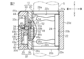
- 2 is a vertical cross-sectional view of the clamp device of FIG. 1 when the operating member is located at the non-operating position.
- FIG. 3 is an exploded perspective view of the clamp device of FIG. 1.
- FIG. 4 is an exploded perspective view of the clamp unit of FIG. 1.
- FIG. 5 is an enlarged sectional view of a main part of the clamp unit shown in FIG. 1.
- FIG. 6 is a rear view of the clamp unit of FIG. 1.
- FIG. 7 is a vertical cross-sectional view of the clamp device of FIG. 1 when the operation member is operated in the pressing release direction.
- 8 is a vertical cross-sectional view of the clamp device of FIG. 1 when the operating member moves from the position of FIG.
- FIG. 9 is a vertical cross-sectional view of the clamp device of FIG. 1, showing the action when a force in the direction of dropping is applied to the clamp device by its own weight.
- FIG. 10 is a vertical cross-sectional view of the clamp unit according to the second embodiment.
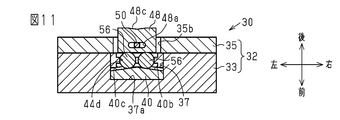
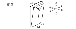
- 11 is a cross-sectional view of the clamp unit of FIG. 12 is a perspective view of a wedge member of the clamp unit of FIG. 13A to 13C are schematic cross-sectional views of a clamp unit according to another embodiment.
- 14A and 14B are schematic cross-sectional views of a clamp unit according to another embodiment.
- FIG. 15 is a schematic front view of a clamp unit according to another embodiment.
- the clamp device 10 includes a bracket 20 and a clamp unit 30 fixed to the bracket 20.
- the material of each component forming the bracket 20 and the clamp unit 30 is metal unless otherwise specified, but is not limited to metal.
- the bracket 20 has a substantially cubic shape and has six faces 20a to 20f.
- the first surface 20a and the second surface (bottom surface) 20b arranged on the opposite sides to each other include the third surface (front side surface) 20c and the fourth surface (rear side surface) 20d which are also arranged on the opposite sides, and Similarly, they are arranged at right angles to the fifth surface (left side surface) 20e and the sixth surface 20f which are arranged on the opposite sides. Further, the third surface 20c and the fourth surface 20d are arranged at right angles to the fifth surface 20e and the sixth surface 20f.
- the bracket 20 has a through hole 22 having a circular cross section that extends from the first surface 20a to the second surface 20b.
- the third surface 20 c of the bracket 20 is provided with a communication hole 23 that intersects the through hole 22 extending in the vertical direction and communicates with the through hole 22.
- the through hole 22 is an example of an insertion part or an insertion hole
- the communication hole 23 is an example of a communication part.
- the through hole 22 has a small diameter portion 22a at both open ends thereof, and a large diameter portion 22b having a diameter slightly larger than the small diameter portion 22a between the both small diameter portions 22a.
- a non-slip sheet 24 having flexibility is attached to a portion of the inner peripheral surface of the large diameter portion 22b corresponding to the fourth surface 20d.
- the non-slip sheet 24 is made of resin, and the step 22c formed between the small diameter portion 22a and the large diameter portion 22b restricts the shift of the through hole 22 in the extending direction.
- the anti-slip sheet 24 suppresses the slip between the bracket 20 and the shaft S when the shaft S, which will be described later, inserted into the through hole 22 is pressed and clamped by the pressing body 48 of the clamp unit 30.
- the fourth surface 20d of the bracket 20 is provided with a connecting portion for connecting with other mechanical parts.
- the shaft S is an example of an object to be clamped.
- the clamp unit 30 is attached to the third surface 20c of the bracket 20.
- the clamp unit 30 includes a case 32, a wedge member 40, two biasing springs 42, an operating member 44, a roller 46, a pressing body 48, a guide shaft 50, a return spring 52, and the like. ..
- the case 32 includes a case body 33 and a mounting plate 35 fixed to the rear surface of the case body 33 by a plurality of bolts 34.
- the rear surface of the case body 33 is a surface facing the third surface (front side surface) 20c of the bracket 20 in FIG.
- the bolt 34 is a hexagon socket head bolt, but the bolt 34 is not limited to the hexagon socket head bolt and may be another bolt.
- the case body 33 and the mounting plate 35 are formed in a square plate shape.
- the case body 33 is thicker than the mounting plate 35, and the four corners 33a on the front side surface are chamfered.
- Each corner 33a is formed with a stepped hole 33b penetrating the case body 33 in the front-rear direction.
- the stepped hole 33b is an example of a mounting portion.
- Insertion holes 35a respectively corresponding to the stepped holes 33b are formed in the four corners of the mounting plate 35.
- Female screw holes 21 are formed in the four corners of the third surface 20c of the bracket 20.
- the case 32 is fixed to the bracket 20 by screwing the mounting bolt 36, which has passed through the stepped hole 33 b of the case main body 33 and the insertion hole 35 a of the mounting plate 35, into the female screw hole 21 of the bracket 20 and tightening the same. ..
- the mounting bolt 36 is a hexagon socket head bolt, but it is not limited to the hexagon socket head bolt and may be another bolt.
- a groove 37 that opens upward and backward is formed in the center of the rear surface of the case body 33.
- Two spring storage holes 33d are formed in the lower end surface of the groove 37.
- the case body 33 has stepped bolt insertion holes 38 extending from the front side surface of the case body 33 to the inner bottom surface 37a of the groove 37.
- the fixing bolt 39 which is inserted into the stepped bolt insertion hole 38 from the front side surface side of the case body 33, is screwed into the wedge member 40 housed in the groove 37 and tightened, so that the wedge member 40 is attached to the inner bottom surface 37a.
- the upper end of the wedge member 40 is arranged so as not to project upward from the upper end opening of the groove 37.
- the entire rear surface of the wedge member 40 is an inclined surface 40a that is one plane and inclines so that the upper portion is located rearward of the lower portion.
- the slope 40a is an example of a facing surface that faces the pressing body 48.
- the case body 33 has a guide groove 33c that extends in the vertical direction from the upper surface of the case body 33 to the upper end of the groove 37. Wider than width.
- an operation member 44 is vertically slidably arranged in the guide groove 33c and the groove 37.
- the upward direction is the pressing promoting direction and the downward direction is the pressing releasing direction.
- the slope 40a of the wedge member 40 is inclined with respect to the pressing promotion direction and the pressing release direction.
- the operating member 44 includes an operating portion 44a at an upper portion, an extending portion 44b extending downward from the operating portion 44a, and a spring receiving portion 44c (see FIG. 2) extending forward from a lower portion of the extending portion 44b. ,have.
- the operation member 44 can move downward until the lower surface of the spring receiving portion 44c comes into contact with the lower end surface of the groove 37.
- the operation portion 44a has a width slightly shorter than the width of the guide groove 33c in the left-right direction.
- the operating member 44 moves in the vertical direction, the operating member 44 is guided by the left and right inner side surfaces of the guide groove 33c.
- the extending portion 44b has a width that is slightly shorter than the width of the groove 37 in the left-right direction. When the operating member 44 moves in the vertical direction, the extending portion 44b is guided by the left and right inner side surfaces of the groove 37.
- the extending portion 44b has a holding hole 44d extending in the left-right direction.
- the holding hole 44d is arranged in the extending portion 44b so as to be located in the groove 37 in any of the vertical movement ranges of the operation member 44.
- a roller 46 having an axial center extending in the left-right direction is rotatably arranged in the holding hole 44d. That is, the extending portion 44b of the operating member 44 is a holder that holds the roller 46.
- the roller 46 is an example of a moving body and a rolling body. The rollers 46 move in the same direction as the operating member 44 when the operating member 44 moves in the vertical direction.
- the roller 46 rotates with the front side of the roller 46 always in contact with the inclined surface 40a of the wedge member 40 and the rear side of the roller 46 in constant contact with the front surface of the pressing body 48.
- the inclined surface 40a of the wedge member 40 is an example of an abutting surface that abuts the roller (moving body and rolling element) 46.
- a biasing spring 42 is arranged between the bottom surface of each spring storage hole 33d and the lower surface of the spring receiving portion 44c of the operation member 44. Both biasing springs 42 constantly bias the operating member 44 in the upward direction, that is, in the pressing promoting direction.
- the biasing spring 42 is an example of a first biasing member.
- the urging spring 42 is a coil spring, but the urging spring 42 is not limited to the coil spring, and may be a leaf spring, for example.
- a rectangular slide hole 35b extending in the up-down direction is transparently provided at the center of the mounting plate 35.
- slide grooves 35c that open toward the case body 33 are formed on both upper and lower end surfaces of the slide hole 35b.
- the slide hole 35b is an example of a guide portion that guides the pressing body 48.
- a substantially rectangular parallelepiped pressing body 48 is fitted in the slide hole 35b so as to be slidable in the vertical direction and the front-back direction.
- the pressing body 48 is arranged so as to face the slope 40a.
- a contact groove 48c having a V-shaped cross section that extends in the vertical direction is formed at the center of the rear surface of the pressing body 48 in the left-right direction.
- the two inner surfaces that define the contact groove 48c can contact the peripheral surface of the shaft S described later.
- the contact groove 48c is an example of a recess.
- the pressing body 48 is movable in the front-back direction, that is, in the direction intersecting the vertical direction, which is the moving direction of the roller 46.
- the pressing body 48 has a guide hole 48a penetrating the pressing body 48 in the vertical direction, and a guide shaft 50 is slidably inserted in the guide hole 48a. That is, the pressing body 48 can slide vertically with respect to the guide shaft 50.
- FIG. 5 illustrates a state in which the upper end of the guide shaft 50 is locked to the inner end surface 35d of the slide groove 35c.
- a spring fitting groove 48b is formed in a portion of the upper end surface of the pressing body 48 corresponding to the guide hole 48a.
- the inner end surface of the spring fitting groove 48b in which the guide hole 48a is opened forms a locking step 48d.
- both ends of a return spring 52 arranged around the guide shaft 50 are locked to the upper end surface of the slide hole 35b and the locking step portion 48d.
- the return spring 52 is a coil spring and constantly presses the pressing body 48 downward.
- the return spring 52 is an example of a second biasing member.
- the return spring 52 is a coil spring in the present embodiment, the return spring 52 is not limited to the coil spring, and may be a leaf spring, for example.
- a spring seat 54 is interposed between the upper end of the return spring 52 and the upper end surface of the slide hole 35b.
- the pressing body 48 is arranged so as to always contact the rear portion of the roller 46.
- the roller 46 pressed by the slope 40a presses the pressing body 48 backward.
- the pressing body 48 can move rearward until the guide shaft 50 is locked to the inner end surface 35d of the slide groove 35c.
- the rearward movement of the pressing body 48 increases the protrusion amount of the pressing body 48 from one side portion of the case 32, that is, the through hole 22 (large diameter portion 22b) of the bracket 20. The amount of the pressing body 48 entering the inside increases.
- the amount by which the pressing body 48 enters the through hole 22 (large diameter portion 22b), that is, the amount by which the pressing body 48 projects from the case 32 can be changed according to the vertical position of the operating member 44. Is becoming When the amount of entry is the maximum (state shown in FIG. 2 ), even if the shaft can be inserted into the small diameter portion 22 a of the through hole 22, the pressing body 48 and the inner circumference of the through hole 22 facing the pressing body 48. A shaft having a diameter larger than the distance from the surface portion interferes with the pressing body 48 and cannot be inserted into the entire through hole 22.
- the position of the operating member 44 when the amount of the pressing body 48 entering the through hole 22 (large diameter portion 22b) is maximum as described above is the non-operating position.
- the operating member 44 When the operating member 44 is moved downward, that is, in the pressing releasing direction, with the shaft S clamped by the pressing portion 48 and the inner peripheral surface portion of the large diameter portion 22b facing the pressing portion 48, the operating member 44 is moved into the through hole 22.
- the pushing amount of the pressing body 48 is smaller than the pushing amount when the shaft S is clamped. As a result, the clamp on the shaft S can be released.
- FIG. 2 shows an initial state in which the operating member 44 is not operated and the shaft S is not inserted into the through hole 22 of the bracket 20.
- the operating member 44 is urged upward by the urging spring 42 to be positioned at the non-operating position.
- the roller 46 maximizes the amount of protrusion of the pressing body 48 into the through hole 22 (large diameter portion 22b) by the action of the inclined surface 40a.
- roller 46 moves downward together with the operation member 44, the regulation of the initial state by the slope 40a is released, and the roller 46 and the pressing body 48 can move in the front-rear direction.
- the arrow B in FIG. 7 indicates the operating direction of the roller 46 and the pressing body 48.
- the spring receiving portion 44c is in contact with the lower end surface of the groove 37 by the downward movement of the operating member 44, but it is not always necessary to operate until the spring receiving portion 44c is in contact with the lower end surface of the groove 37. It is not necessary to move member 44 downward. That is, a position where the protrusion amount of the pressing body 48 can be reduced, and a separation distance between the pressing body 48 and the inner peripheral surface portion of the through hole 22 facing the pressing body 48 can be made larger than the diameter of the shaft S. Up to this, the operation member 44 may be moved downward.
- each contact groove 48c is pressed by the outer peripheral surface of the shaft S and moves forward together with the roller 46. ..
- the load applied to the shaft S is only the load based on the urging force of the urging spring 42.
- the arrow C in FIG. 8 indicates the direction in which the biasing force of the biasing spring 42 acts.
- the arrow D in FIG. 8 indicates the direction in which the pressing body 48 acts (direction toward the shaft S).
- part of the force in the direction in which the clamp device 10 falls due to its own weight presses the pressing body 48 toward the shaft S due to the interaction between the slope 40a and the roller 46. Since the force is converted into force, the clamp device 10 does not fall.
- the arrow F indicates the direction of the force that presses the pressing body 48 toward the shaft S.
- the bracket 20 may be removed from the shaft S.
- the surface pressure acting on the object to be clamped by the rolling element tends to be high, which may cause deformation of the object to be clamped.
- the pressing body 48 is provided with the contact groove 48c.
- the two inner surfaces that define the contact groove 48c contact the peripheral surface of the shaft S, respectively. Therefore, the surface pressure acting on the shaft S can be reduced, and the deformation of the shaft S can be suppressed more effectively.
- the clamp unit 30 having the stepped hole 33b that is the attachment portion can be attached to the bracket 20. Therefore, it is also possible to attach the common clamp unit 30 to the brackets 20 of various sizes that can be inserted with the clamped objects having different diameters. Even if the diameters of the objects to be clamped are different, the clamp unit 30 can be shared, so that the number of parts can be reduced and the cost can be suppressed.
- the present embodiment has the following features.
- the clamp unit 30 of the present embodiment is provided in the case 32, the case 32, the operation member 44 arranged in the case 32 so as to be reciprocally movable with respect to the case 32 in the pressing releasing direction and the pressing promoting direction.
- a pressing body 48 arranged so as to face the inclined surface 40a (opposing surface and contact surface).
- the pressing body 48 is movably arranged in the case 32 so that the amount of protrusion from one side of the case 32 can be changed.
- the moving direction of the pressing body 48 intersects with the moving direction of the operating member 44, that is, the pressing releasing direction and the pressing promoting direction, and more specifically, is orthogonal.
- the slope 40a is inclined with respect to the pressing release direction and the pressing promotion direction.
- the clamp unit 30 is provided with a roller 46 (moving body) which is arranged between the pressing body 48 and the slope 40a and is in contact with the pressing body 48 and the slope 40a.
- the roller 46 moves together with the operating member 44 along the pressing body 48 and the inclined surface 40a according to the movement of the operating member 44 in each of the pressing releasing direction and the pressing promoting direction.
- the roller 46 is also movable in the same direction as the moving direction of the pressing body 48.
- the slope 40a increases the protrusion amount of the pressing body 48 from the case 32 due to the position change of the roller 46 due to the movement of the operation member 44 in the pressing promotion direction.
- the slope 40a loosens the pressing of the roller 46 against the pressing body 48 by the position change of the roller 46 accompanying the movement of the operating member 44 in the pressing release direction, and allows the amount of protrusion of the pressing body 48 from the case 32 to be reduced. ..
- the clamp unit 30 also includes a biasing spring 42 (first biasing member) that biases the operation member 44 in the pressing promotion direction.
- the case 32 is configured to be attached to the bracket 20 into which the object to be clamped is inserted.
- the case 32 has a stepped hole 33b (mounting portion), and is attached to the bracket 20 at the stepped hole 33b.
- the clamp unit can be made common and the number of parts can be reduced, and the cost can be suppressed.
- the case 32 has a slide hole 35b (guide portion) for guiding the movement of the pressing body 48 in the direction in which the protrusion amount of the pressing body 48 changes.
- the pressing body 48 can move favorably in the direction in which the amount of protrusion thereof changes.
- the slide hole 35b (guide portion) is further configured to guide the movement of the pressing body 48 along the pressing promotion direction of the operation member 44. Further, the clamp unit 30 urges the pressing body 48 in the direction opposite to the direction in which the position of the roller 46 (moving body) changes, in other words, in the same direction as the pressing release direction, the return spring 52 (second urging member). have.
- the clamp device 10 when the operating load on the operating member 44 is removed when the shaft S is clamped, the clamp device 10 tries to drop due to its own weight, while the pressing body 48 includes the pressing body 48 and the shaft S. The frictional force between them tries to maintain the positional relationship with respect to the shaft S. Therefore, the portion of the clamp device 10 other than the pressing body 48 slightly moves downward against the biasing force of the return spring 52. Then, a part of the force in the direction in which the clamp device 10 falls due to its own weight is converted into a force for pressing the pressing body 48 toward the shaft S by the interaction between the slope 40a and the roller 46. Therefore, the clamp device 10 does not drop, and the shaft S can be firmly clamped.
- the contact groove 48c (recess) that extends along the direction in which the shaft S extends is provided on the surface of the pressing body 48 that faces the shaft S (object to be clamped). There is. Therefore, the surface pressure acting on the shaft S is reduced, and the deformation of the shaft S can be suppressed.
- the moving body (rolling body) arranged between the pressing body 48 and the slope 40a is the roller 46. Since the roller 46 rolls well between the pressing body 48 and the slope 40a, the operation member 44 can be operated easily.
- the clamp device 10 of this embodiment includes a clamp unit 30 and a bracket 20.
- the bracket 20 has a through hole 22 into which the shaft S (object to be clamped) is inserted, and a communication hole 23 (communication portion) that extends in a direction intersecting the direction in which the through hole 22 extends and communicates with the through hole 22. doing.
- the pressing body 48 can enter the communication hole 23.
- the clamp unit 30 is attached to the bracket 20 at the stepped hole 33b (attachment portion).
- the second embodiment differs from the first embodiment in that the configuration of the wedge member 40 is different from that in the first embodiment, and that two balls are provided as rolling elements (moving elements).
- the rear surface of the wedge member 40 is formed with two inclined surface portions 40b and 40c.
- the slope portions 40b and 40c are flat surfaces and intersect each other at a predetermined angle so as to form a mountain shape in cross section as a whole.
- the slopes 40b and 40c are also inclined so that the upper portion is located rearwardly of the lower portion.
- the two slope portions 40b and 40c are examples of slopes (opposing surface and contact surface) that are inclined with respect to the pressing release direction and the pressing promotion direction.
- two balls 56 are arranged between the slopes 40b and 40c and the front surface of the pressing body 48.
- the ball 56 is an example of a sphere, a moving body, and a rolling body.
- the cross section of the guide hole 48a is formed in an elongated hole shape extending in the left-right direction so that the pressing body 48 can move in the left-right direction with respect to the guide shaft 50.
- the pressing body 48 is freely movable in the left-right direction with respect to the guide shaft 50, when the pressing body 48 comes into contact with the object to be clamped, depending on the outer diameter shape of the object to be clamped. This is so that the person can move to an appropriate position.
- the operation member 44 is operated in the same manner as in the first embodiment, so that the through hole 22 of the bracket 20 is inserted. It is possible to firmly clamp the inserted shaft S.
- the present embodiment as shown in FIG. 11, since the two balls 56 press the pressing body 48 not only backward but also laterally by the action of the slopes 40b and 40c, the lateral clamping force is also increased. Can be demonstrated.
- FIGS. 13A to 13C, 14A and 14B A modified example of the slope inclined with respect to the pressing release direction and the pressing promotion direction will be described below with reference to FIGS. 13A to 13C, 14A and 14B. It should be noted that the description will be focused on the configuration different from that of the first embodiment, and the same or corresponding configurations as those of the first embodiment will be denoted by the reference numerals given to the first embodiment and detailed description thereof will be omitted. Although the urging spring 42 for urging the operation member 44 in the pressing promoting direction is not shown in each drawing, it should be understood that the urging spring 42 is actually present.
- the wedge member 40 is omitted in the embodiment of FIG. 13A.
- the inner bottom surface 37a (the surface facing the pressing body 48) of the groove 37 of the case main body 33 is a flat surface, and the operation member 44 moves vertically with the spring receiving portion 44c of the operation member 44 in contact with the inner bottom surface 37a. Can be moved. Further, the rolling element 60, which is a moving body held in the holding hole 44d of the operation member 44, is in rolling contact with the inner bottom surface 37a.
- the rolling element 60 is a ball or a cylindrical roller.
- the front surface 48e of the pressing body 48 facing the inner bottom surface 37a is an inclined surface that is inclined so as to approach the case main body 33 toward the upper portion, and contacts the rolling element 60.
- the embodiment of FIG. 13B is a combination of the configuration of the first embodiment and the configuration of the embodiment of FIG. 13A. That is, the configuration of this embodiment includes the wedge member 40 having the slope 40a and the pressing body 48 having the slope 48e.
- the rolling element 60 is changed to a moving body 62 having a trapezoidal cross section.
- the rear surface 62a of the moving body 62 is a slant surface that is in sliding contact with the front surface (slope) 48e of the pressing body 48
- the front surface 62b of the moving body 62 is a slant surface that is in sliding contact with the slant surface 40a of the wedge member 40.
- the spring receiving portion 44c is arranged so as not to interfere with the slope 40a and the front surface 48e when the operation member 44 moves in the vertical direction.
- a guide groove 37b extending in the up-down direction is formed on at least one of the left and right inner side surfaces of the groove 37.
- the operation member 44 has a guide protrusion (not shown) that engages with the guide groove 37b, and the vertical movement of the operation member 44 is guided by the guide groove 37b.
- the inclined surface 40a of the wedge member 40 and the front surface 62b of the moving body 62 are examples of facing surfaces that face each other.
- the rear surface 62a of the moving body 62 and the front surface 48e of the pressing body 48 are examples of facing surfaces that face each other.
- the moving body 62 may be a member separate from the operation member 44, or may be formed integrally with the operation member 44.
- the wedge member 40 is omitted from the configuration of FIG. 13C.
- the inner bottom surface 37a (the surface facing the pressing body 48) of the groove 37 of the case body 33 is a flat surface.
- the moving body 62 can move in the vertical direction with its front surface 62b in contact with the inner bottom surface 37a.
- the front surface 62b of the moving body 62 is not an inclined surface but a flat surface parallel to the pressing release direction and the pressing promotion direction.
- the rear surface 62a of the moving body 62 and the front surface 48e of the pressing body 48 are both facing surfaces facing each other and are inclined surfaces.
- the rear surface 62a of the moving body 62 and the front surface 48e of the pressing body 48 are changed from a slope to a plane parallel to the pressing release direction and the pressing promotion direction.
- the sloped surface 40a of the wedge member 40 and the front surface 62b of the moving body 62 are sloped surfaces as well as facing surfaces facing each other.
- the pressing promoting direction and the pressing releasing direction of the operating member 44 are not limited to the vertical direction, and may be configured as shown in FIG. 15, for example.
- a disc-shaped operation member 144 rotatably supported is provided instead of the operation member 44 that moves in the vertical direction.
- the operation member 144 is rotatably supported by the case body 33 by a rotation shaft 145 extending in the front-rear direction.
- An operating lever 146 protruding in the radial direction is provided on the outer peripheral portion of the operating member 144, and an operator can operate the operating lever 146 from the outside of the case body 33.
- the clockwise direction is the pressing promotion direction and the counterclockwise direction is the pressing release direction.
- the operation member 144 has a holding hole 144d at a position 180 degrees away from the operation lever 146 with respect to the rotary shaft 145, and the rolling element 60 is held in the holding hole 144d.
- the rolling element 60 may be a ball or a roller.
- the rolling element 60 is always in contact with an inclined surface 40a (see FIG. 2) of the wedge member 40, which is arranged along the movement trajectory of the rolling element 60 and basically has the same configuration as that of the first embodiment.
- the operation member 144 is constantly urged in the pressing promotion direction by, for example, a twist coil spring (not shown) wound around the rotating shaft 145 (first urging member).
- a twist coil spring wound around the rotating shaft 145 (first urging member).
- the operating member 144 is locked by a stopper (not shown) and is arranged at the non-operating position.
- the rolling element 60 moves the inclined surface 40a of the wedge member 40 to loosen the pressing force of the pressing element 48.
- the operation member 144 rotates in the pressing promotion direction together with the rolling element 60 by the urging force of the first urging member, and the rolling element 60 presses the pressing body 48. Even with such a configuration, the same operational effect as that of the first embodiment can be obtained.
- FIG. 15 it is also possible to adopt the configurations of the moving body and the slope shown in FIGS. 13A to 14B. Further, it is possible to set the clockwise direction as the pressing release direction and the counterclockwise direction as the pressing promotion removing direction. Further, the arrangement of the operation lever 146 is not limited to the arrangement shown in FIG. 15, and can be changed as appropriate.
- the object to be clamped is not limited to the shaft S, and may be any object as long as it can be inserted into the through hole 22 of the bracket 20.
- the wedge member 40 may be a member separate from the case body 33, or may be formed integrally with the case body 33.
- the cross-sectional shape of the through hole 22 is not limited to a circle, and may be a polygon such as a triangle, a quadrangle, a pentagon, a hexagon, or another shape such as an ellipse.
- the mounting portion may have a configuration other than the stepped hole 33b as long as the clamp unit 30 can be mounted on the bracket.
- a bolt insertion hole may be provided in the bracket, and the bolt inserted in the bolt insertion hole may be screwed into a female screw hole that is a mounting portion provided in the clamp unit 30.
- the clamp unit 30 may be detachably attached to the bracket 20.
- the number may be singular or plural.
- the insertion part into which the object to be clamped is not limited to the through hole 22, and may be, for example, a groove having a C-shaped cross section formed on the bracket 20.
- the object to be clamped is inserted into a groove having a C-shaped cross section.
- the communication part into which the pressing body can enter communicates with the insertion part in a direction orthogonal (crossing) to the extending direction of the insertion part having a C-shaped cross section.
Landscapes
- Engineering & Computer Science (AREA)
- General Engineering & Computer Science (AREA)
- Mechanical Engineering (AREA)
- Clamps And Clips (AREA)
Abstract
クランプユニットは、当接面を有するケースと、ケースに対して押圧解除方向及び押圧促進方向へ往復移動自在な操作部材と、当接面と向き合うようにケースに移動自在に配置された押圧体と、押圧体と当接面との間に配置される移動体と、を備える。当接面、移動体、及び押圧体のうち、少なくとも1つには斜面が設けられる。斜面は、操作部材の押圧促進方向への移動に伴う移動体の位置変化によって、ケースからの押圧体の突出量を増大させる一方、操作部材の押圧解除方向への移動に伴う移動体の位置変化によって、押圧体に対する移動体の押圧を緩めて、ケースからの押圧体の突出量の減少を許容する。
Description
本開示は、クランプユニット及びクランプ装置に関する。
特許文献1は、管等のシャフトをクランプするクランプ装置を開示している。特許文献1のクランプ装置は、断面円形の貫通孔を有するストッパ本体を有しており、前記貫通孔を挿通したシャフトに対してストッパ本体が着脱自在に装着される。前記貫通孔の内面には、前記シャフトの延伸方向に沿って徐々に径が小さくなるくさび状空間を形成する傾斜面が設けられている。
前記貫通孔内には保持器が配置されている。保持器は、前記シャフトが挿通される挿通孔を中央に有するとともに、ボール或いはコロ等の複数の転動体を保持している。貫通孔内にはさらに、前記保持器を前記くさび状空間の径が小さくなる方向へ押圧するスプリングが設けられている。
また、前記クランプ装置は、前記保持器をくさび状空間の径が大きくなる方向に移動させる、レバー等の転動体解放手段を有している。
前記スプリングが前記保持器を前記くさび状空間の径が小さくなる方向に押圧して移動させると、前記転動体がシャフトの表面と前記傾斜面とに圧接され、それにより、シャフトがクランプされる。
上記のクランプ装置では、ストッパ本体、保持器、及び該保持器に保持される転動体として、シャフトの径に応じて異なるサイズのものを用意する必要があることから、コスト高となる。
本開示の目的は、クランプ対象物の径が異なっていても、クランプユニットを共通化して部品点数を少なくすることが可能となり、コストを抑制することができるクランプユニット及びクランプ装置を提供することにある。
本開示の一態様のクランプユニットは、当接面を有するケースと、前記ケースに対して押圧解除方向及び押圧促進方向へ往復移動自在であるように前記ケースに配置された操作部材と、前記当接面と向き合うように配置された押圧体であって、前記ケースの一側部からの突出量が変化可能なように前記ケースに移動自在に配置された押圧体と、前記押圧体と前記当接面との間に配置されるとともに前記押圧体と前記当接面とに当接する移動体であって、前記押圧解除方向及び前記押圧促進方向の各々への前記操作部材の移動に応じて前記押圧体と前記当接面とに沿って移動するように構成された移動体と、前記操作部材を前記押圧促進方向へ付勢する第1付勢部材と、を備える。前記当接面、前記当接面に当接する前記移動体の部位、前記前記押圧体に当接する前記移動体の部位、及び前記移動体に当接する前記押圧体の部位のうち、少なくとも1つには、前記押圧解除方向及び前記押圧促進方向に対して傾斜した斜面が設けられ、前記斜面は、前記操作部材の前記押圧促進方向への移動に伴う前記移動体の位置変化によって、前記ケースからの前記押圧体の突出量を増大させる一方、前記操作部材の前記押圧解除方向への移動に伴う前記移動体の位置変化によって、前記押圧体に対する前記移動体の押圧を緩めて、前記ケースからの前記押圧体の突出量の減少を許容する、ように構成される。前記ケースは取付部を有し、該取付部において、クランプ対象物が挿入されるブラケットに取り付けられるように構成される。
また、本開示の一態様のクランプ装置は、前記クランプユニットと、クランプ対象物が挿入される挿入部と、前記挿入部が延びる方向とは交差する方向で前記挿入部に連通するとともに前記押圧体が進入可能な連通部と、を有しているブラケットと、を備える。前記クランプユニットが前記取付部にて前記ブラケットに対して取り付けられている。
(第1実施形態)
図1~図9を参照して、以下、一実施形態のクランプ装置10とクランプユニット30とを説明する。
図1~図9を参照して、以下、一実施形態のクランプ装置10とクランプユニット30とを説明する。
なお、説明の便宜上、図1に示すように、図1の図面を基準にして、上下左右及び前後を定義する。
図1、図3に示すようにクランプ装置10は、ブラケット20と、ブラケット20に固定されたクランプユニット30とを備えている。ブラケット20及びクランプユニット30を構成する各部品の材質は特に断らない限り金属であるが、金属に限定するものではない。
ブラケット20は、略立方体状をなしていて、6つの面20a~20fを備えている。相互に反対側に配置された第1面20aと第2面(下面)20bは、同じく相互に反対側に配置された第3面(前側面)20cと第4面(後側面)20d、並びに同じく相互に反対側に配置された第5面(左側面)20eと第6面20fに対して直角に配置されている。また、第3面20cと第4面20dは、第5面20eと第6面20fに対して直角に配置されている。
図1、図3に示すように、ブラケット20は、第1面20aから第2面20bまで延びる断面円形の貫通孔22を有している。図3に示すように、ブラケット20の第3面20cには、上下方向に延びる貫通孔22に対して交差し且つ該貫通孔22に連通した連通孔23が穿設されている。貫通孔22は挿入部又は挿入孔の一例であり、連通孔23は連通部の一例である。
貫通孔22は、その両開口端部に小径部22aを有し、両小径部22aの間に小径部22aよりも若干径が大きい大径部22bを有している。図1、図2に示すように、大径部22bの内周面のうち、第4面20dと対応する部位には、可撓性を有する滑り止めシート24が貼着されている。滑り止めシート24は、樹脂製であって、小径部22aと大径部22bとの間に形成された段差22cによって、貫通孔22の延出方向へのずれが規制されている。
滑り止めシート24は、貫通孔22に挿通された後述するシャフトSが、クランプユニット30の押圧体48によって押圧されてクランプされた際、ブラケット20とシャフトSとの間の滑りを抑制する。図示はしないがブラケット20の第4面20dには、他の機械部品と連結する連結部が設けられている。シャフトSはクランプ対象物の一例である。
ブラケット20の第3面20cには、クランプユニット30が取付けられている。図4に示すようにクランプユニット30は、ケース32、楔部材40、2つの付勢バネ42、操作部材44、コロ46、押圧体48、ガイド軸50、及び復帰バネ52等を有している。
ケース32は、ケース本体33と、ケース本体33の後面に対して複数のボルト34によって固定された取付板35と、を含む。ケース本体33の後面は、図3において、ブラケット20の第3面(前側面)20cに対向する面である。本実施形態では、ボルト34は六角穴付ボルトであるが、六角穴付ボルトに限定されるものではなく、他のボルトであってもよい。
図1、図3に示すように、ケース本体33及び取付板35は、四角板状に形成されている。ケース本体33は、取付板35よりも肉厚であり、前側面の4つのコーナ33aが面取りされている。各コーナ33aには、ケース本体33を前後方向に貫通する段付き孔33bが形成されている。段付き孔33bは、取付部の一例である。取付板35の4つのコーナには、段付き孔33bにそれぞれ対応する挿通孔35a(図4参照)が形成されている。ブラケット20の第3面20cの4つのコーナには、雌ネジ孔21が形成されている。
ケース本体33の段付き孔33b及び取付板35の挿通孔35aを通った取付ボルト36が、ブラケット20の雌ネジ孔21に螺合して締め付けられることにより、ケース32がブラケット20に固定される。本実施形態では、取付ボルト36は六角穴付ボルトであるが、六角穴付ボルトに限定されるものではなく、他のボルトであってもよい。
図4に示すように、ケース本体33の後面の中央には、上方及び後方に向けて開口する溝37が形成されている。溝37の下端面には2つのバネ収納穴33dが形成されている。
図2に示すように、ケース本体33は、ケース本体33の前側面から溝37の内底面37aにまで延びる段付きボルト挿通孔38を有している。ケース本体33の前側面側から段付きボルト挿通孔38に挿通された固定ボルト39が、溝37に収納された楔部材40に螺合されて締め付けられることにより、楔部材40が内底面37aに固定される。図2に示すように、楔部材40の上端は、溝37の上端開口から上方へ突出しないように配置されている。楔部材40の後面全体は、下部よりも上部の方が後方に位置するように傾く、一平面からなる斜面40aである。斜面40aは、押圧体48に対向する対向面の一例である。
図1、図4に示すように、ケース本体33は、ケース本体33の上面から前記溝37の上端まで上下方向に延びるガイド溝33cを有し、該ガイド溝33cは、左右方向において溝37の幅よりも広い。
図2~図4に示すように、ガイド溝33c及び溝37には、操作部材44が上下方向に摺動自在に配置されている。本実施形態では、操作部材44の移動方向に関して、上方向が押圧促進方向であり下方向が押圧解除方向である。前記楔部材40の斜面40aは、押圧促進方向及び押圧解除方向に対して傾斜している。操作部材44は、上部にある操作部44aと、操作部44aから下方へ延出する延出部44bと、延出部44bの下部から前方へ延出するバネ受け部44c(図2参照)と、を有している。
操作部材44は、バネ受け部44cの下面が溝37の下端面に当接するまで、下方へ移動可能である。操作部44aは、左右方向においてガイド溝33cの幅よりも若干短い幅を有している。操作部材44が上下方向に移動する際、操作部材44はガイド溝33cの左右の内側面によってガイドされる。また、延出部44bは、左右方向において溝37の幅よりも若干短い幅を有している。操作部材44が上下方向に移動する際、延出部44bは溝37の左右の内側面によってガイドされる。
図4に示すように延出部44bは、左右方向に延びる保持孔44dを有する。保持孔44dは、操作部材44の上下方向の移動範囲のいずれにおいても溝37内に位置するように、延出部44bに配置されている。図2に示すように保持孔44d内には、左右方向に延びる軸心を有するコロ46が回動自在に配置されている。すなわち、操作部材44の延出部44bは、コロ46を保持する保持器である。コロ46は移動体及び転動体の一例である。コロ46は、操作部材44が上下方向へ移動する際に、操作部材44ととともに同方向に移動する。この際、コロ46の前部側が楔部材40の斜面40aに常時当接し且つコロ46の後部側が押圧体48の前面と常時当接した状態で、コロ46は回転する。楔部材40の斜面40aは、コロ(移動体及び転動体)46に当接する当接面の一例である。
図2に示すように、各バネ収納穴33dの底面と操作部材44のバネ受け部44cの下面との間には、付勢バネ42が配置されている。両付勢バネ42は、常時、操作部材44を上方向、すなわち押圧促進方向へ付勢している。付勢バネ42は、第1付勢部材の一例である。なお、本実施形態では、付勢バネ42はコイルスプリングであるが、コイルスプリングに限定されるものではなく、例えば板バネであってもよい。
図4、図6に示すように、取付板35の中央部には、上下方向に延びる長方形状のスライド孔35bが透設されている。図2、図4及び図5に示すように、スライド孔35bの上下両端面には、ケース本体33に向かって開口するスライド溝35cがそれぞれ形成されている。スライド孔35bは、押圧体48をガイドするガイド部の一例である。
前記スライド孔35bには、略直方体状の押圧体48が上下方向に及び前後方向にスライド自在に嵌合されている。押圧体48は斜面40aと対向するように配置されている。押圧体48の後面の左右方向の中央には、上下方向に延びる断面V字状の当接溝48cが形成されている。当接溝48cを画定する2つの内面は、後述するシャフトSの周面に当接可能である。当接溝48cは、凹部の一例である。
押圧体48は前後方向、すなわちコロ46の移動方向である上下方向に対して交差する方向、に移動可能である。
図2に示すように押圧体48は、押圧体48を上下方向に貫通するガイド孔48aを有し、ガイド軸50がガイド孔48aにスライド自在に挿通されている。すなわち、押圧体48は、ガイド軸50に対して上下方向にスライド可能である。
図5に示すように、ガイド軸50の上下両端は、それぞれスライド溝35cに対して前後方向にスライド自在に嵌合されている。ガイド軸50の後方への移動は、ガイド軸50がスライド溝35cの内端面35dに係止されるまで可能である。図5では、ガイド軸50の上端がスライド溝35cの内端面35dに係止された状態が図示されている。
図5に示すように、押圧体48の上端面のうち、ガイド孔48aと対応する部位には、スプリング嵌合溝48bが形成されている。ガイド孔48aが開口するスプリング嵌合溝48bの内端面は係止段部48dを形成している。
図5に示すようにスライド孔35bの上端面と係止段部48dとには、ガイド軸50の周囲に配置された復帰バネ52の両端が係止されている。復帰バネ52は、コイルスプリングであり、押圧体48を下方へ常時押圧している。復帰バネ52は第2付勢部材の一例である。なお、本実施形態では、復帰バネ52はコイルスプリングであるが、コイルスプリングに限定されるものではなく、例えば板バネであってもよい。復帰バネ52の上端とスライド孔35bの上端面との間には、バネ座54が介装されている。
図2、図5に示すように、押圧体48は、コロ46の後部に常時当接するように配置されている。操作部材44が上方(押圧促進方向)へ移動すると、斜面40aによって押圧されたコロ46が押圧体48を後方へ押圧する。この際、ガイド軸50がスライド溝35cの内端面35dに係止されるまで、押圧体48は後方へ移動可能である。この押圧体48の後方への移動により、図2に示すように、ケース32の一側部からの押圧体48の突出量が増大する、すなわち、ブラケット20の貫通孔22(大径部22b)内への押圧体48の進入量が増大する。
また、操作部材44が下方へ移動すると、斜面40aによるコロ46を介しての押圧体48に対する押圧が解除されるので、押圧体48及びガイド軸50は前方への移動が許容される。これにより、ケース32の一側部からの押圧体48の突出量、すなわち、ブラケット20の貫通孔22(大径部22b)内への押圧体48の進入量、が減少可能となっている。
上記のように貫通孔22(大径部22b)内への押圧体48の進入量、すなわちケース32からの押圧体48の突出量は、操作部材44の上下方向の位置に応じて変更可能となっている。なお、前記進入量が最大の場合(図2で示す状態)、貫通孔22の小径部22aに挿入可能なシャフトであっても、押圧体48と押圧体48に対向する貫通孔22の内周面部位との間の離間距離よりも大きい径を有するシャフトは、押圧体48と干渉するので貫通孔22全体に挿入することはできない。
上記のように貫通孔22(大径部22b)内への押圧体48の進入量が最大の場合の操作部材44の位置を非操作位置とする。
シャフトSが押圧部48と押圧部48に対向する大径部22bの内周面部位とによってクランプされた状態で、操作部材44を下方、すなわち押圧解除方向へ移動させると、貫通孔22内への押圧体48の進入量がシャフトSをクランプしているときの進入量よりも減少する。これにより、シャフトSに対するクランプの解除が可能となる。
(第1実施形態の作用)
図2、図7~図9を参照して上記クランプ装置10及びクランプユニット30の作用を説明する。説明の便宜上、上下に延びるように配置されているシャフトSに対して上記クランプ装置10をクランプする場合について説明する。
図2、図7~図9を参照して上記クランプ装置10及びクランプユニット30の作用を説明する。説明の便宜上、上下に延びるように配置されているシャフトSに対して上記クランプ装置10をクランプする場合について説明する。
<1.初期状態>
図2は、操作部材44が操作されておらず、ブラケット20の貫通孔22内にシャフトSが挿通されていない初期状態を示している。
図2は、操作部材44が操作されておらず、ブラケット20の貫通孔22内にシャフトSが挿通されていない初期状態を示している。
この場合、操作部材44は付勢バネ42によって上方向へ付勢されることにより、非操作位置に位置する。コロ46は、斜面40aの作用によって、貫通孔22(大径部22b)内への押圧体48の突出量を最大にしている。
従って、貫通孔22の小径部22aに挿入可能なシャフトであっても、押圧体48と押圧体48に対向する貫通孔22の内周面部位との離間距離よりも大きい径を有するシャフトは、上記クランプ装置10によってクランプすることはできない。なお、押圧体48は、その下面がスライド孔35bの下端面に当接するように、復帰バネ52によって付勢されている。
<2.操作部材44の操作>
図7に示すように、作業者が、付勢バネ42の付勢力に抗して、操作部材44を非操作位置から、下方(押圧解除方向)へ押下げ操作する。図7の矢印Aは、操作部材44に対して操作荷重が作用する方向を示している。
図7に示すように、作業者が、付勢バネ42の付勢力に抗して、操作部材44を非操作位置から、下方(押圧解除方向)へ押下げ操作する。図7の矢印Aは、操作部材44に対して操作荷重が作用する方向を示している。
この操作により、コロ46は、操作部材44とともに下方へ移動し、斜面40aによる初期状態の規制が解除されて、コロ46及び押圧体48の前後方向への移動が可能となる。図7の矢印Bは、コロ46及び押圧体48の作動方向を示している。
なお、図7では、操作部材44の下方への移動により、バネ受け部44cが溝37の下端面に当接しているが、必ずしも、バネ受け部44cが溝37の下端面に当接するまで操作部材44を下方へ移動させる必要はない。すなわち、押圧体48の突出量を減少可能とする位置であって、押圧体48と押圧体48に対向する貫通孔22の内周面部位との離間距離をシャフトSの径よりも大きくできる位置まで、操作部材44を下方へ移動させればよい。
操作部材44を下方へ押下げ操作した状態で、シャフトSをブラケット20に挿入すると、押圧体48、すなわち各当接溝48cがシャフトSの外周面に押圧されて、コロ46とともに前方へ移動する。
<3.操作部材44を押し込んでいた操作荷重を取り除いただけの状態>
図8に示すように、次に、操作部材44を押し込んでいた操作荷重を取り除くと、付勢バネ42の付勢力で、操作部材44及びコロ46は上方(押圧促進方向)へ移動する。すると、コロ46が楔部材40の斜面40aの作用により押圧体48をシャフトSに押し付ける。
図8に示すように、次に、操作部材44を押し込んでいた操作荷重を取り除くと、付勢バネ42の付勢力で、操作部材44及びコロ46は上方(押圧促進方向)へ移動する。すると、コロ46が楔部材40の斜面40aの作用により押圧体48をシャフトSに押し付ける。
この状態では、シャフトSに掛かる荷重は、付勢バネ42の付勢力に基づく荷重のみである。図8の矢印Cは、付勢バネ42の付勢力が作用する方向を示している。図8の矢印Dは、押圧体48が作用する方向(シャフトSへ向かう方向)を示している。
<4.クランプ装置10の自重による作用>
操作部材44に対する操作荷重が除去されると、自重によりクランプ装置10が落下しようとする。このとき、押圧体48は、押圧体48とシャフトSとの間の摩擦力により、シャフトSに対する位置関係を維持しようとする。よって、クランプ装置10のうち、押圧体48以外の部分は、復帰バネ52の付勢力に抗して下方へ若干移動する。
操作部材44に対する操作荷重が除去されると、自重によりクランプ装置10が落下しようとする。このとき、押圧体48は、押圧体48とシャフトSとの間の摩擦力により、シャフトSに対する位置関係を維持しようとする。よって、クランプ装置10のうち、押圧体48以外の部分は、復帰バネ52の付勢力に抗して下方へ若干移動する。
また、クランプ装置10が自重により落下する方向の力(図9の矢印Eが向く方向)の一部が、斜面40aとコロ46との相互作用により、押圧体48をシャフトSに向かって押圧する力に変換されるため、クランプ装置10が落下することはない。図9において、矢印Fは押圧体48をシャフトSに向かって押圧する力の方向を示している。
<5.クランプ装置10の取り外し>
シャフトSからクランプ装置10を取外す際には、上記した<2.操作部材44の操作>と同様に、図7に示すように、作業者が、付勢バネ42の付勢力に抗して、操作部材44を下方(押圧解除方向)へ押下げ操作してクランプを解除すればよい。
シャフトSからクランプ装置10を取外す際には、上記した<2.操作部材44の操作>と同様に、図7に示すように、作業者が、付勢バネ42の付勢力に抗して、操作部材44を下方(押圧解除方向)へ押下げ操作してクランプを解除すればよい。
この操作により、コロ46は、操作部材44とともに下方へ下がり、斜面40aによる初期状態の規制が解除される。押圧体48は、復帰バネ52の付勢力により、図2に示すように、スライド孔35bの下端面に当接する。
この結果、コロ46及び押圧体48の前後方向への移動が可能となるため、ブラケット20をシャフトSから取り外せばよい。
転動体自体でクランプ対象物を把持する場合は、転動体からクランプ対象物に作用する面圧が高くなる傾向にあり、このため、クランプ対象物が変形する可能性があるが、本実施形態では、このようなことはない。すなわち、転動体であるコロ46とクランプ対象物であるシャフトSとの間に押圧体48を介在させることで、シャフトSに作用する面圧が小さくなり、シャフトSの変形が抑制される。特に、本実施形態では、押圧体48には当接溝48cが設けられている。当接溝48cを画定する2つの内面は、シャフトSの周面にそれぞれ当接する。このため、シャフトSに作用する面圧を下げて、シャフトSの変形をより効果的に抑制することができる。
従来のクランプ装置では、クランプ装置を構成する各部品として、クランプ対象物であるシャフトの径に応じて異なるサイズのものを用意する必要があるので、コスト高となる。
これに対して、本実施形態のクランプ装置10では、取付部である段付き孔33bを有するクランプユニット30を、ブラケット20に対して取付けることができる。このため、異なる径を有するクランプ対象物を挿通することが可能な種々の大きさのブラケット20に対して、共通のクランプユニット30を取付けることも可能である。クランプ対象物の径が異なっていても、クランプユニット30は共通化することができるので、部品点数を少なくできてコストを抑制することができる。
本実施形態は、下記の特徴を有する。
(1)本実施形態のクランプユニット30は、ケース32と、ケース32に対して押圧解除方向及び押圧促進方向へ往復動作自在にケース32に配置された操作部材44と、ケース32内に設けられた斜面40a(対向面及び当接面)と向き合うように配置された押圧体48と、を備えている。押圧体48は、ケース32の一側部からの突出量が変化可能なように、ケース32に移動自在に配置されている。押圧体48の移動方向は、操作部材44の移動方向、すなわち、押圧解除方向及び押圧促進方向と交差、より詳細には直交している。斜面40aは押圧解除方向及び押圧促進方向に対して傾斜している。また、クランプユニット30は、押圧体48と斜面40aとの間に配置されるとともに押圧体48と斜面40aとに当接するコロ46(移動体)を備えている。コロ46は、押圧解除方向及び押圧促進方向の各々への操作部材44の移動に応じて、押圧体48と斜面40aとに沿って、操作部材44と共に移動する。コロ46はまた、押圧体48の移動方向と同方向に移動可能である。斜面40aは、操作部材44の押圧促進方向への移動に伴うコロ46の位置変化によって、ケース32からの押圧体48の突出量を増大させる。斜面40aは、操作部材44の押圧解除方向への移動に伴うコロ46の位置変化によって、押圧体48に対するコロ46の押圧を緩めて、ケース32からの押圧体48の突出量の減少を許容する。また、クランプユニット30は、操作部材44を押圧促進方向へ付勢する付勢バネ42(第1付勢部材)を備える。ケース32は、クランプ対象物が挿入されるブラケット20に取付けられるように構成されている。ケース32は段付き孔33b(取付部)を備えており、この段付き孔33bにおいてブラケット20に取付けられる。
この結果、本実施形態によれば、クランプ対象物の径が異なっていても、クランプユニットを共通化して部品点数を少なくすることが可能となり、コストを抑制することができる。
(2)ケース32は、押圧体48の突出量が変化する方向への押圧体48の動きをガイドするスライド孔35b(ガイド部)を有している。本実施形態によれば、押圧体48はその突出量が変化する方向へ良好に動くことができる。
(3)スライド孔35b(ガイド部)は、さらに、操作部材44の押圧促進方向に沿った押圧体48の動きをガイドするように構成されている。また、クランプユニット30は、押圧体48を、コロ46(移動体)の位置が変化する方向と逆方向、言い換えれば押圧解除方向と同じ方向に付勢する復帰バネ52(第2付勢部材)を有している。
本実施形態によれば、シャフトSのクランプ時において、操作部材44に対する操作荷重が除去されると、自重によりクランプ装置10が落下しようとする一方、押圧体48は、押圧体48とシャフトSとの間の摩擦力により、シャフトSに対する位置関係を維持しようとする。よって、クランプ装置10のうち、押圧体48以外の部分は、復帰バネ52の付勢力に抗して下方へ若干移動する。そして、クランプ装置10が自重により落下する方向の力の一部が、斜面40aとコロ46との相互作用により、押圧体48をシャフトSに向かって押圧する力に変換される。そのため、クランプ装置10が落下することがなく、強固にシャフトSをクランプすることができる。
(4)本実施形態のクランプユニット30では、シャフトS(クランプ対象物)に対向する押圧体48の面には、シャフトSが延びる方向に沿って延びる当接溝48c(凹部)が設けられている。このため、シャフトSに作用する面圧が小さくなり、シャフトSの変形が抑制できる。
(5)本実施形態のクランプユニット30では、押圧体48と斜面40aとの間に配置される移動体(転動体)がコロ46である。コロ46は押圧体48と斜面40aとの間を良好に転動するので、操作部材44の操作を楽に行うことができる。
(6)本実施形態のクランプ装置10は、クランプユニット30とブラケット20とを備えている。ブラケット20は、シャフトS(クランプ対象物)が挿入される貫通孔22と、貫通孔22が延びる方向とは交差する方向に延びて貫通孔22に連通する連通孔23(連通部)とを有している。押圧体48は連通孔23に進入可能である。クランプユニット30は段付き孔33b(取付部)においてブラケット20に対して取り付けられている。
この結果、本実施形態によれば、上記(1)に記載の利点を備えたクランプ装置が得られる。
(第2実施形態)
図10~図12を参照して、次に第2実施形態のクランプユニット30について説明する。なお、本実施形態では、第1実施形態のクランプユニット30と同一の又は相当する構成については、同一符号を付してその詳細説明を省略し、異なる構成を中心に説明する。
図10~図12を参照して、次に第2実施形態のクランプユニット30について説明する。なお、本実施形態では、第1実施形態のクランプユニット30と同一の又は相当する構成については、同一符号を付してその詳細説明を省略し、異なる構成を中心に説明する。
本第2実施形態では、楔部材40の構成が第1実施形態と異なるとともに、転動体(移動体)として2つのボールが設けられているところが第1実施形態と異なっている。
図10、図11及び図12に示すように、楔部材40の後面には、2つの斜面部40b、40cが形成されている。図11に示すように斜面部40b、40cはそれぞれ平面であり、全体として断面山形状をなすように所定角度で相互に交差している。斜面部40b、40cはまた、下部よりも上部の方が後方に位置するように傾いている。2つの斜面部40b、40cは、押圧解除方向及び押圧促進方向に対して傾斜した斜面(対向面及び当接面)の一例である。図10及び図11に示すように、斜面部40b、40cと押圧体48の前面との間には2つのボール56が配置されている。ボール56は球体、移動体及び転動体の一例である。
図11に示すように、ガイド軸50に対して押圧体48が左右方向へ移動自在となるように、ガイド孔48aの断面形状は左右方向に延びる長孔状に形成されている。ガイド軸50に対して押圧体48を左右方向へ移動自在にしているのは、クランプ対象物に対して押圧体48が当接した際に、クランプ対象物の外径形状に応じて押圧体48が適切な位置へ移動できるようにするためである。
上記のクランプユニット30を第1実施形態のブラケット20に組付けることによって構成されたクランプ装置10では、第1実施形態と同様にして操作部材44を操作することにより、ブラケット20の貫通孔22に挿通されたシャフトSを強固にクランプすることが可能となる。特に本実施形態では、図11に示すように、斜面部40b、40cの作用により、2つのボール56が後方へだけでなく左右方向へも押圧体48を押圧するため、左右方向へのクランプ力も発揮することができる。
なお、上記各実施形態は、以下のように変更して実施することができる。上記各実施形態及び以下の変更例は、技術的に矛盾しない範囲で互いに組み合わせて実施することができる。
・押圧解除方向及び押圧促進方向に対して傾斜した斜面の変更例について、図13A~図13C、図14A及び図14Bを参照して以下に説明する。なお、第1実施形態と異なる構成を中心に説明し、第1実施形態と同一の又は相当する構成については、第1実施形態に付した符号を付してその詳細な説明を省略する。なお、各図とも、操作部材44を押圧促進方向へ付勢する付勢バネ42の図示はされていないが、付勢バネ42は実際にはあるものとして理解されたい。
図13Aの実施形態では、楔部材40が省略されている。ケース本体33の溝37の内底面37a(押圧体48と対向する面)は平面であり、内底面37aに操作部材44のバネ受け部44cが当接した状態で、操作部材44が上下方向へ移動可能である。また、操作部材44の保持孔44dに保持された移動体である転動体60は、内底面37aに転動自在に当接している。
転動体60は、ボール或いは円柱状のコロである。内底面37aに向き合う押圧体48の前面48eは、上側の部位ほどケース本体33に近づくように傾斜した斜面であり、転動体60に当接する。
図13Bの実施形態は、第1実施形態の構成に、図13Aの実施形態の構成を組み合わせたものである。すなわち、この実施形態の構成は、斜面40aを有する楔部材40と、斜面48eを有する押圧体48とを備えている。
図13Cの実施形態では、図13Bの実施形態の変更例であって、転動体60が断面台形状をなす移動体62に変更されている。移動体62の後面62aは、押圧体48の前面(斜面)48eに摺接する斜面であり、移動体62の前面62bは、楔部材40の斜面40aに摺接する斜面である。
図13B及び図13Cの実施形態では、バネ受け部44cは、操作部材44が上下方向に移動した際に、斜面40a及び前面48eに干渉しないように配置されている。また、溝37の左右の内側面のうちの少なくとも一方には、上下方向に延びるガイド溝37bが形成されている。操作部材44はガイド溝37bに係合する図示しないガイド凸部を有し、操作部材44の上下方向への移動がガイド溝37bによってガイドされる。楔部材40の斜面40a、及び移動体62の前面62bは、相互に対向する対向面の一例である。また、移動体62の後面62a、及び押圧体48の前面48eは、相互に対向する対向面の一例である。
なお、移動体62は、操作部材44とは別部材であってもよく、操作部材44と一体に形成してもよい。
図14Aの実施形態では、図13Cの構成から楔部材40が省略されている。ケース本体33の溝37の内底面37a(押圧体48と対向する面)は平面である。移動体62は、その前面62bが内底面37aに当接した状態で、上下方向に移動可能である。移動体62の前面62bは斜面ではなく、押圧解除方向及び押圧促進方向に対して平行な平面である。移動体62の後面62a及び押圧体48の前面48eは、相互に対向する対向面であるとともに斜面である。
図14Bの実施形態では、図13Cの構成において、移動体62の後面62a及び押圧体48の前面48eが斜面から、押圧解除方向及び押圧促進方向に対して平行な平面に変更されている。楔部材40の斜面40a及び移動体62の前面62bは、相互に対向する対向面であるとともに斜面である。
図13A~図14Bの実施形態においても、第1実施形態と同様の作用効果を奏することができる。
・上記各実施形態において、操作部材44の押圧促進方向及び押圧解除方向は、上下方向に限定されるものではなく、例えば図15に示すような構成としてもよい。
図15の実施形態では、第1実施形態の構成において、上下方向に移動する操作部材44の代わりに、回転自在に支持された円板状の操作部材144が設けられている。操作部材144は、ケース本体33に対して、前後方向に延びる回転軸145により回転自在に支持されている。この操作部材144の外周部には放射方向に突出した操作レバー146が設けられ、作業者はこの操作レバー146をケース本体33の外部から操作可能である。図15において、時計回り方向を押圧促進方向とし、反時計回り方向を押圧解除方向としている。操作部材144は、操作レバー146から回転軸145に関して180度離れた箇所に保持孔144dを有し、この保持孔144dには転動体60が保持されている。転動体60は、ボールでもよく、或いはコロでもよい。転動体60は、転動体60の移動軌跡に沿って配置された、第1実施形態と基本的に同様の構成を有する楔部材40の斜面40a(図2参照)に常時当接している。
操作部材144は、例えば、回転軸145に巻回された図示しないひねりコイルバネ等(第1付勢部材)により、押圧促進方向へ常時付勢されている。クランプ対象物をクランプしない状態では、操作部材144は図示しないストッパに係止されて非操作位置に配置される。
操作レバー146によって操作部材144を非操作位置から押圧解除方向へ回動させると、転動体60は、楔部材40の斜面40aを移動することにより、押圧体48の押圧を緩める。この状態から操作部材144に対する操作を解除すると、操作部材144が第1付勢部材の付勢力によって転動体60とともに押圧促進方向へ回動し、転動体60が押圧体48を押圧する。このように構成しても、第1実施形態と同様の作用効果を奏する。
図15の構成において、図13A~図14Bに示される移動体及び斜面の構成を採用することも可能である。さらに、時計回り方向を押圧解除方向とし、反時計回り方向を押促進除方向とすることも可能である。また、操作レバー146の配置は、図15に示す配置に限定されるものではなく、適宜変更することも可能である。
・クランプ対象物はシャフトSに限定されるものではなく、ブラケット20の貫通孔22に挿通されるものであれば、どのようなものでもよい。
・楔部材40はケース本体33と別部材でもよいし、ケース本体33に一体に形成されてもよい。
・貫通孔22の断面形状は、円形に限定されることはなく、三角形、四角形、五角形、六角形等の多角形、或いは楕円形等の他の形状であってもよい。
・取付部は、ブラケットに対してクランプユニット30を取付けることができるのであれば、段付き孔33b以外の構成であってもよい。例えば、ブラケットにボルト挿通孔を設け、そのボルト挿通孔に挿通されたボルトを、クランプユニット30に設けられた取付部である雌ネジ孔に螺合してもよい。
・ブラケット20に対してクランプユニット30を着脱自在に取り付けてもよい。
・移動体が球体である場合、その個数は単数であっても複数であってもよい。
・クランプ対象物が挿入される挿入部は、貫通孔22に限定されるものではなく、例えば、ブラケット20に形成された断面C字形状の溝であってもよい。クランプ対象物は断面C字形状の溝内に挿入される。押圧体が進入可能な連通部は、断面C字形状の挿入部が延出する方向に直交(交差)する方向で挿入部に連通する。
Claims (10)
- 当接面を有するケースと、
前記ケースに対して押圧解除方向及び押圧促進方向へ往復移動自在であるように前記ケースに配置された操作部材と、
前記当接面と向き合うように配置された押圧体であって、前記ケースの一側部からの突出量が変化可能なように前記ケースに移動自在に配置された押圧体と、
前記押圧体と前記当接面との間に配置されるとともに前記押圧体と前記当接面とに当接する移動体であって、前記押圧解除方向及び前記押圧促進方向の各々への前記操作部材の移動に応じて前記押圧体と前記当接面とに沿って移動するように構成された移動体と、
前記操作部材を前記押圧促進方向へ付勢する第1付勢部材と、を備え、
前記当接面、前記当接面に当接する前記移動体の部位、前記前記押圧体に当接する前記移動体の部位、及び前記移動体に当接する前記押圧体の部位のうち、少なくとも1つには、前記押圧解除方向及び前記押圧促進方向に対して傾斜した斜面が設けられ、前記斜面は、
前記操作部材の前記押圧促進方向への移動に伴う前記移動体の位置変化によって、前記ケースからの前記押圧体の突出量を増大させる一方、
前記操作部材の前記押圧解除方向への移動に伴う前記移動体の位置変化によって、前記押圧体に対する前記移動体の押圧を緩めて、前記ケースからの前記押圧体の突出量の減少を許容する、ように構成され、
前記ケースは取付部を有し、該取付部において、クランプ対象物が挿入されるブラケットに取り付けられるように構成される、クランプユニット。 - 前記斜面は、前記当接面及び前記押圧体のうち、少なくともいずれか一方に設けられる、請求項1に記載のクランプユニット。
- 前記斜面は、
前記操作部材の前記押圧促進方向への移動に伴い、前記移動体を前記押圧体に向かって押圧し、それによって前記ケースからの前記押圧体の突出量を増大させる一方、
前記操作部材の前記押圧解除方向への移動に伴い、前記押圧体から離れる方向への前記移動体の移動を許容し、それによって前記ケースからの前記押圧体の突出量の減少を許容する、ように構成される、請求項1又は請求項2に記載のクランプユニット。 - 前記ケースは、前記押圧体の突出量が変化する方向への前記押圧体の動きをガイドするガイド部を有する、請求項1乃至請求項3のうちいずれか一項に記載のクランプユニット。
- 前記ガイド部は、前記押圧促進方向に沿った前記押圧体の動きをガイドするように構成されており、
前記押圧体を前記押圧解除方向に付勢する第2付勢部材をさらに備える、請求項4に記載のクランプユニット。 - 前記押圧体は、前記クランプ対象物に対向する部位に、前記クランプ対象物が延びる方向に沿って延びる凹部を有する、請求項1乃至請求項5のうちいずれか一項に記載のクランプユニット。
- 前記移動体は転動体であり、
前記斜面は、前記押圧体及び前記当接面のうち、少なくともいずれか一方に設けられている、請求項1乃至請求項6のうちいずれか一項に記載のクランプユニット。 - 前記移動体は2つの球体であり、
前記斜面は、所定角度で相互に交差するように前記当接面に設けられた2つの斜面部であり、
前記2つの球体は、前記2つの斜面部にそれぞれ当接する、請求項1乃至請求項6のうちいずれか一項に記載のクランプユニット。 - 前記移動体は、前記押圧体及び前記当接面にそれぞれ当接する2つの対向面を有し、
前記斜面は、
前記2つの対向面のうちの一方の対向面、及びその一方の対向面に当接する前記押圧体又は前記当接面の各々に設けられる、或いは、
前記2つの対向面、並びにそれら2つの対向面にそれぞれ当接する前記押圧体及び前記当接面の各々に設けられる、請求項1乃至請求項6のうちいずれか一項に記載のクランプユニット。 - 請求項1乃至請求項9のうちいずれか一項に記載のクランプユニットと、
クランプ対象物が挿入される挿入部と、前記挿入部が延びる方向とは交差する方向で前記挿入部に連通するとともに前記押圧体が進入可能な連通部と、を有しているブラケットと、を備え、
前記クランプユニットが前記取付部において前記ブラケットに対して取り付けられているクランプ装置。
Priority Applications (4)
| Application Number | Priority Date | Filing Date | Title |
|---|---|---|---|
| US17/056,916 US11592043B2 (en) | 2018-12-14 | 2019-12-10 | Clamp unit and clamp device |
| CN201980029579.5A CN112055786B (zh) | 2018-12-14 | 2019-12-10 | 夹紧装置 |
| KR1020207025408A KR102778087B1 (ko) | 2018-12-14 | 2019-12-10 | 클램프 유닛 및 클램프 장치 |
| EP19894784.8A EP3896294B1 (en) | 2018-12-14 | 2019-12-10 | Clamp unit and clamp device |
Applications Claiming Priority (2)
| Application Number | Priority Date | Filing Date | Title |
|---|---|---|---|
| JP2018-234180 | 2018-12-14 | ||
| JP2018234180A JP7114073B2 (ja) | 2018-12-14 | 2018-12-14 | クランプユニット及びクランプ装置 |
Publications (1)
| Publication Number | Publication Date |
|---|---|
| WO2020122035A1 true WO2020122035A1 (ja) | 2020-06-18 |
Family
ID=71076347
Family Applications (1)
| Application Number | Title | Priority Date | Filing Date |
|---|---|---|---|
| PCT/JP2019/048172 Ceased WO2020122035A1 (ja) | 2018-12-14 | 2019-12-10 | クランプユニット及びクランプ装置 |
Country Status (6)
| Country | Link |
|---|---|
| US (1) | US11592043B2 (ja) |
| EP (1) | EP3896294B1 (ja) |
| JP (1) | JP7114073B2 (ja) |
| KR (1) | KR102778087B1 (ja) |
| CN (1) | CN112055786B (ja) |
| WO (1) | WO2020122035A1 (ja) |
Citations (4)
| Publication number | Priority date | Publication date | Assignee | Title |
|---|---|---|---|---|
| JPS6298010A (ja) * | 1985-10-23 | 1987-05-07 | 富士工業株式会社 | 移動部材のロツク装置 |
| JPH042609Y2 (ja) * | 1985-09-20 | 1992-01-29 | ||
| JP2008057753A (ja) * | 2006-09-04 | 2008-03-13 | Matsuda Metal Mfg Co Ltd | 吊持構造 |
| JP2014066365A (ja) | 2009-12-28 | 2014-04-17 | Talk System Co Ltd | リニアストッパ |
Family Cites Families (19)
| Publication number | Priority date | Publication date | Assignee | Title |
|---|---|---|---|---|
| US2954638A (en) * | 1959-11-04 | 1960-10-04 | Morton Mfg Company | Upright locking socket |
| US3491614A (en) * | 1968-07-18 | 1970-01-27 | Bendix Corp | Collapsible steering column |
| DE2406609C2 (de) * | 1973-11-08 | 1984-04-05 | Kürbi & Niggeloh, 5608 Radevormwald | Stativ |
| DE2647664C3 (de) * | 1976-06-30 | 1981-01-15 | Takara Seisakusho Co., Ltd., Osaka (Japan) | Kamerastativ |
| US4278224A (en) * | 1977-06-30 | 1981-07-14 | Arakawa, Co. Ltd. | Wedging action fixture |
| DE3319042A1 (de) * | 1983-05-26 | 1984-11-29 | Wabco Westinghouse Steuerungstechnik GmbH & Co, 3000 Hannover | Brems- oder/und klemmeinrichtung |
| US4900182A (en) * | 1989-03-22 | 1990-02-13 | Stillwagon Applied Techonology Incorporated | Lock and release apparatus |
| FR2702809B1 (fr) * | 1993-03-17 | 1995-05-19 | Christian Banquet | Bras télescopique. |
| GB2306587B (en) * | 1995-11-01 | 1999-06-30 | Framo Eng As | Fluid flow connector |
| IT1285239B1 (it) * | 1996-02-14 | 1998-06-03 | Danilo Baruffaldi | Dispositivo di bloccaggio dello scorrimento dello stelo di un attuatore lineare, ed attuatore lineare munito di tale dispositivo |
| DE10140561A1 (de) * | 2001-08-17 | 2003-02-27 | Ina Schaeffler Kg | Klemmgesperre |
| DE102005040811A1 (de) * | 2004-03-02 | 2007-03-01 | Mobilitas Deininger Gmbh | Klemmmechanismus |
| ITVE20090052A1 (it) * | 2009-09-18 | 2011-03-19 | Euro Consultants Uk Ltd | Dispositivo autobloccante per aste tubolari telescopiche.- |
| TWM392885U (en) * | 2010-04-09 | 2010-11-21 | Ming Ren Hang Co Ltd | Elevation adjustment apparatus for rod member |
| GB2487822B (en) * | 2011-01-26 | 2013-07-10 | Gripple Ltd | Clamping assembly |
| DE102012014754A1 (de) * | 2012-07-26 | 2014-01-30 | Christian Kögel | Fixierelement zur werkzeuglosen Befestigung von Gegenständen an einem Seil |
| GB201219119D0 (en) * | 2012-10-24 | 2012-12-05 | Gripple Ltd | Clamping assembly |
| US9220346B1 (en) * | 2014-09-30 | 2015-12-29 | Yen-Feng Wu | Pedal-ring tightening structure |
| JP6661357B2 (ja) * | 2015-12-07 | 2020-03-11 | 株式会社Tok | ロッド固定ユニット |
-
2018
- 2018-12-14 JP JP2018234180A patent/JP7114073B2/ja active Active
-
2019
- 2019-12-10 WO PCT/JP2019/048172 patent/WO2020122035A1/ja not_active Ceased
- 2019-12-10 CN CN201980029579.5A patent/CN112055786B/zh active Active
- 2019-12-10 US US17/056,916 patent/US11592043B2/en active Active
- 2019-12-10 EP EP19894784.8A patent/EP3896294B1/en active Active
- 2019-12-10 KR KR1020207025408A patent/KR102778087B1/ko active Active
Patent Citations (4)
| Publication number | Priority date | Publication date | Assignee | Title |
|---|---|---|---|---|
| JPH042609Y2 (ja) * | 1985-09-20 | 1992-01-29 | ||
| JPS6298010A (ja) * | 1985-10-23 | 1987-05-07 | 富士工業株式会社 | 移動部材のロツク装置 |
| JP2008057753A (ja) * | 2006-09-04 | 2008-03-13 | Matsuda Metal Mfg Co Ltd | 吊持構造 |
| JP2014066365A (ja) | 2009-12-28 | 2014-04-17 | Talk System Co Ltd | リニアストッパ |
Non-Patent Citations (1)
| Title |
|---|
| See also references of EP3896294A4 |
Also Published As
| Publication number | Publication date |
|---|---|
| KR102778087B1 (ko) | 2025-03-10 |
| JP7114073B2 (ja) | 2022-08-08 |
| KR20210103390A (ko) | 2021-08-23 |
| US11592043B2 (en) | 2023-02-28 |
| CN112055786A (zh) | 2020-12-08 |
| CN112055786B (zh) | 2023-07-11 |
| EP3896294A4 (en) | 2022-08-17 |
| EP3896294B1 (en) | 2024-04-24 |
| EP3896294A1 (en) | 2021-10-20 |
| JP2020094658A (ja) | 2020-06-18 |
| US20210207632A1 (en) | 2021-07-08 |
Similar Documents
| Publication | Publication Date | Title |
|---|---|---|
| US6336531B1 (en) | Braking disc assembly | |
| JP5936355B2 (ja) | 横方向に位置するケージを備えた摩擦ロック装置 | |
| US8434976B2 (en) | Small hole saw mandrel assembly | |
| US9994128B2 (en) | Seat sliding device for vehicle | |
| US9555524B2 (en) | Clamping device for clamping a fastener | |
| US20050252323A1 (en) | Moving body and actuating device having the same | |
| JP2014024493A (ja) | ステアリング装置 | |
| JP2013505838A5 (ja) | ||
| CN103252510A (zh) | 用于夹紧带有凹口的切削镶片的带有凸起的刀具夹持器 | |
| CN102281977A (zh) | 夹紧式刀具夹持器 | |
| KR20190131126A (ko) | 로드 캐리어 풋 | |
| US6427896B1 (en) | Safety device for pneumatic nailers | |
| WO2020122035A1 (ja) | クランプユニット及びクランプ装置 | |
| CA2906913C (en) | Tensioned brake pad | |
| US20130008280A1 (en) | Brake handle | |
| GB2583179A (en) | Ball clamping mechanism and bicycle carrier including the same | |
| US6745874B1 (en) | Anti-brake system for bicycles | |
| US20240318699A1 (en) | Adjustable parallelism brake device for brake pads | |
| EP1925843B1 (en) | Gap adjusting mechanism of a wet brake | |
| KR101329039B1 (ko) | 스티어링 칼럼의 틸트 잠금 및 잠금 해제 구조 | |
| JPH0218835Y2 (ja) | ||
| CN101400906A (zh) | 移动装置 | |
| JP4477535B2 (ja) | 移動装置 | |
| JP4516879B2 (ja) | 突張装置 | |
| WO2019098086A1 (ja) | 運動案内装置のレールカバー |
Legal Events
| Date | Code | Title | Description |
|---|---|---|---|
| 121 | Ep: the epo has been informed by wipo that ep was designated in this application |
Ref document number: 19894784 Country of ref document: EP Kind code of ref document: A1 |
|
| ENP | Entry into the national phase |
Ref document number: 20207025408 Country of ref document: KR Kind code of ref document: A |
|
| NENP | Non-entry into the national phase |
Ref country code: DE |
|
| ENP | Entry into the national phase |
Ref document number: 2019894784 Country of ref document: EP Effective date: 20210714 |