WO2020122056A1 - Ventilateur intégré à un moteur, et engin de décollage et d'atterrissage vertical - Google Patents
Ventilateur intégré à un moteur, et engin de décollage et d'atterrissage vertical Download PDFInfo
- Publication number
- WO2020122056A1 WO2020122056A1 PCT/JP2019/048227 JP2019048227W WO2020122056A1 WO 2020122056 A1 WO2020122056 A1 WO 2020122056A1 JP 2019048227 W JP2019048227 W JP 2019048227W WO 2020122056 A1 WO2020122056 A1 WO 2020122056A1
- Authority
- WO
- WIPO (PCT)
- Prior art keywords
- air
- motor
- cooling
- outer peripheral
- integrated fan
- Prior art date
- Legal status (The legal status is an assumption and is not a legal conclusion. Google has not performed a legal analysis and makes no representation as to the accuracy of the status listed.)
- Ceased
Links
Images






Classifications
-
- F—MECHANICAL ENGINEERING; LIGHTING; HEATING; WEAPONS; BLASTING
- F04—POSITIVE - DISPLACEMENT MACHINES FOR LIQUIDS; PUMPS FOR LIQUIDS OR ELASTIC FLUIDS
- F04D—NON-POSITIVE-DISPLACEMENT PUMPS
- F04D25/00—Pumping installations or systems
- F04D25/02—Units comprising pumps and their driving means
- F04D25/08—Units comprising pumps and their driving means the working fluid being air, e.g. for ventilation
- F04D25/082—Units comprising pumps and their driving means the working fluid being air, e.g. for ventilation the unit having provision for cooling the motor
-
- B—PERFORMING OPERATIONS; TRANSPORTING
- B64—AIRCRAFT; AVIATION; COSMONAUTICS
- B64C—AEROPLANES; HELICOPTERS
- B64C11/00—Propellers, e.g. of ducted type; Features common to propellers and rotors for rotorcraft
- B64C11/001—Shrouded propellers
-
- B—PERFORMING OPERATIONS; TRANSPORTING
- B64—AIRCRAFT; AVIATION; COSMONAUTICS
- B64C—AEROPLANES; HELICOPTERS
- B64C29/00—Aircraft capable of landing or taking-off vertically, e.g. vertical take-off and landing [VTOL] aircraft
-
- B—PERFORMING OPERATIONS; TRANSPORTING
- B64—AIRCRAFT; AVIATION; COSMONAUTICS
- B64D—EQUIPMENT FOR FITTING IN OR TO AIRCRAFT; FLIGHT SUITS; PARACHUTES; ARRANGEMENT OR MOUNTING OF POWER PLANTS OR PROPULSION TRANSMISSIONS IN AIRCRAFT
- B64D33/00—Arrangement in aircraft of power plant parts or auxiliaries not otherwise provided for
- B64D33/02—Arrangement in aircraft of power plant parts or auxiliaries not otherwise provided for of combustion air intakes
-
- B—PERFORMING OPERATIONS; TRANSPORTING
- B64—AIRCRAFT; AVIATION; COSMONAUTICS
- B64D—EQUIPMENT FOR FITTING IN OR TO AIRCRAFT; FLIGHT SUITS; PARACHUTES; ARRANGEMENT OR MOUNTING OF POWER PLANTS OR PROPULSION TRANSMISSIONS IN AIRCRAFT
- B64D33/00—Arrangement in aircraft of power plant parts or auxiliaries not otherwise provided for
- B64D33/04—Arrangement in aircraft of power plant parts or auxiliaries not otherwise provided for of exhaust outlets or jet pipes
-
- B—PERFORMING OPERATIONS; TRANSPORTING
- B64—AIRCRAFT; AVIATION; COSMONAUTICS
- B64D—EQUIPMENT FOR FITTING IN OR TO AIRCRAFT; FLIGHT SUITS; PARACHUTES; ARRANGEMENT OR MOUNTING OF POWER PLANTS OR PROPULSION TRANSMISSIONS IN AIRCRAFT
- B64D33/00—Arrangement in aircraft of power plant parts or auxiliaries not otherwise provided for
- B64D33/08—Arrangement in aircraft of power plant parts or auxiliaries not otherwise provided for of power plant cooling systems
-
- B—PERFORMING OPERATIONS; TRANSPORTING
- B64—AIRCRAFT; AVIATION; COSMONAUTICS
- B64U—UNMANNED AERIAL VEHICLES [UAV]; EQUIPMENT THEREFOR
- B64U30/00—Means for producing lift; Empennages; Arrangements thereof
- B64U30/20—Rotors; Rotor supports
-
- B—PERFORMING OPERATIONS; TRANSPORTING
- B64—AIRCRAFT; AVIATION; COSMONAUTICS
- B64U—UNMANNED AERIAL VEHICLES [UAV]; EQUIPMENT THEREFOR
- B64U50/00—Propulsion; Power supply
- B64U50/10—Propulsion
- B64U50/19—Propulsion using electrically powered motors
-
- F—MECHANICAL ENGINEERING; LIGHTING; HEATING; WEAPONS; BLASTING
- F04—POSITIVE - DISPLACEMENT MACHINES FOR LIQUIDS; PUMPS FOR LIQUIDS OR ELASTIC FLUIDS
- F04D—NON-POSITIVE-DISPLACEMENT PUMPS
- F04D25/00—Pumping installations or systems
- F04D25/02—Units comprising pumps and their driving means
-
- F—MECHANICAL ENGINEERING; LIGHTING; HEATING; WEAPONS; BLASTING
- F04—POSITIVE - DISPLACEMENT MACHINES FOR LIQUIDS; PUMPS FOR LIQUIDS OR ELASTIC FLUIDS
- F04D—NON-POSITIVE-DISPLACEMENT PUMPS
- F04D25/00—Pumping installations or systems
- F04D25/02—Units comprising pumps and their driving means
- F04D25/06—Units comprising pumps and their driving means the pump being electrically driven
- F04D25/0606—Units comprising pumps and their driving means the pump being electrically driven the electric motor being specially adapted for integration in the pump
- F04D25/066—Linear Motors
-
- F—MECHANICAL ENGINEERING; LIGHTING; HEATING; WEAPONS; BLASTING
- F04—POSITIVE - DISPLACEMENT MACHINES FOR LIQUIDS; PUMPS FOR LIQUIDS OR ELASTIC FLUIDS
- F04D—NON-POSITIVE-DISPLACEMENT PUMPS
- F04D29/00—Details, component parts, or accessories
- F04D29/58—Cooling; Heating; Diminishing heat transfer
- F04D29/5806—Cooling the drive system
-
- F—MECHANICAL ENGINEERING; LIGHTING; HEATING; WEAPONS; BLASTING
- F04—POSITIVE - DISPLACEMENT MACHINES FOR LIQUIDS; PUMPS FOR LIQUIDS OR ELASTIC FLUIDS
- F04D—NON-POSITIVE-DISPLACEMENT PUMPS
- F04D29/00—Details, component parts, or accessories
- F04D29/66—Combating cavitation, whirls, noise, vibration or the like; Balancing
- F04D29/68—Combating cavitation, whirls, noise, vibration or the like; Balancing by influencing boundary layers
- F04D29/681—Combating cavitation, whirls, noise, vibration or the like; Balancing by influencing boundary layers especially adapted for elastic fluid pumps
-
- F—MECHANICAL ENGINEERING; LIGHTING; HEATING; WEAPONS; BLASTING
- F04—POSITIVE - DISPLACEMENT MACHINES FOR LIQUIDS; PUMPS FOR LIQUIDS OR ELASTIC FLUIDS
- F04D—NON-POSITIVE-DISPLACEMENT PUMPS
- F04D29/00—Details, component parts, or accessories
- F04D29/66—Combating cavitation, whirls, noise, vibration or the like; Balancing
- F04D29/68—Combating cavitation, whirls, noise, vibration or the like; Balancing by influencing boundary layers
- F04D29/681—Combating cavitation, whirls, noise, vibration or the like; Balancing by influencing boundary layers especially adapted for elastic fluid pumps
- F04D29/687—Plasma actuators therefore
-
- H—ELECTRICITY
- H02—GENERATION; CONVERSION OR DISTRIBUTION OF ELECTRIC POWER
- H02K—DYNAMO-ELECTRIC MACHINES
- H02K7/00—Arrangements for handling mechanical energy structurally associated with dynamo-electric machines, e.g. structural association with mechanical driving motors or auxiliary dynamo-electric machines
- H02K7/14—Structural association with mechanical loads, e.g. with hand-held machine tools or fans
-
- H—ELECTRICITY
- H02—GENERATION; CONVERSION OR DISTRIBUTION OF ELECTRIC POWER
- H02K—DYNAMO-ELECTRIC MACHINES
- H02K9/00—Arrangements for cooling or ventilating
- H02K9/02—Arrangements for cooling or ventilating by ambient air flowing through the machine
- H02K9/04—Arrangements for cooling or ventilating by ambient air flowing through the machine having means for generating a flow of cooling medium
- H02K9/06—Arrangements for cooling or ventilating by ambient air flowing through the machine having means for generating a flow of cooling medium with fans or impellers driven by the machine shaft
-
- H—ELECTRICITY
- H02—GENERATION; CONVERSION OR DISTRIBUTION OF ELECTRIC POWER
- H02K—DYNAMO-ELECTRIC MACHINES
- H02K9/00—Arrangements for cooling or ventilating
- H02K9/22—Arrangements for cooling or ventilating by solid heat conducting material embedded in, or arranged in contact with, the stator or rotor, e.g. heat bridges
- H02K9/227—Heat sinks
-
- B—PERFORMING OPERATIONS; TRANSPORTING
- B64—AIRCRAFT; AVIATION; COSMONAUTICS
- B64D—EQUIPMENT FOR FITTING IN OR TO AIRCRAFT; FLIGHT SUITS; PARACHUTES; ARRANGEMENT OR MOUNTING OF POWER PLANTS OR PROPULSION TRANSMISSIONS IN AIRCRAFT
- B64D33/00—Arrangement in aircraft of power plant parts or auxiliaries not otherwise provided for
- B64D33/02—Arrangement in aircraft of power plant parts or auxiliaries not otherwise provided for of combustion air intakes
- B64D2033/024—Arrangement in aircraft of power plant parts or auxiliaries not otherwise provided for of combustion air intakes comprising cooling means
-
- Y—GENERAL TAGGING OF NEW TECHNOLOGICAL DEVELOPMENTS; GENERAL TAGGING OF CROSS-SECTIONAL TECHNOLOGIES SPANNING OVER SEVERAL SECTIONS OF THE IPC; TECHNICAL SUBJECTS COVERED BY FORMER USPC CROSS-REFERENCE ART COLLECTIONS [XRACs] AND DIGESTS
- Y02—TECHNOLOGIES OR APPLICATIONS FOR MITIGATION OR ADAPTATION AGAINST CLIMATE CHANGE
- Y02T—CLIMATE CHANGE MITIGATION TECHNOLOGIES RELATED TO TRANSPORTATION
- Y02T50/00—Aeronautics or air transport
- Y02T50/60—Efficient propulsion technologies, e.g. for aircraft
Definitions
- the present invention relates to a motor-integrated fan provided with a cooling flow path and a vertical take-off and landing aircraft.
- UAV cooling system that uses an airflow generated by a fan provided in a UAV (unmanned aerial vehicle) to cool devices arranged in the fan (see, for example, Patent Document 1).
- the fan is a ducted fan and has a fan shaft, a fan blade, and a fan motor.
- the airflow generated by the fan blades is used to remove heat from the equipment.
- an object of the present invention is to provide a motor-integrated fan and a vertical take-off and landing machine that are provided with a cooling flow path that can appropriately remove heat from the heat generating portion while suppressing reduction in fan performance.
- a motor-integrated fan of the present invention is a motor-integrated fan that sucks air from a suction port and blows the sucked air from an outlet, and a shaft portion provided at the center of a rotation shaft and a rotation that rotates around the shaft portion.
- the cooling unit includes an air intake port that takes in the cooling air, an air discharge port that discharges the cooling air, and a cooling flow path that extends from the air intake port to the air discharge port through the heat generating unit.
- the air outlet is provided at a position where the pressure is negative compared to the air inlet.
- the cooling air is taken in from the air inlet, and the cooling air after passing through the heat generating portion is discharged from the air outlet. You can Therefore, the heat of the heat generating portion can be suitably removed by the cooling air. Further, since the negative pressure of the air outlet with respect to the air inlet is used, it is possible to suppress the reduction in fan performance.
- the heat generating portion may be a motor or may be something other than a motor, and is not particularly limited.
- the heat generating portion and the cooling portion are provided on the outer peripheral portion
- the air intake port is provided on the outer peripheral surface of the outer peripheral portion
- the air discharge port is provided on the inner peripheral surface of the outer peripheral portion. It is preferable that it is provided on the upstream side of the rotating portion in the flow direction of the air flowing from the suction port toward the air outlet.
- the cooling portion takes in air from the outer peripheral surface of the outer peripheral portion having an atmospheric pressure and the inner peripheral surface of the outer peripheral portion on the upstream side of the rotating portion where the pressure becomes low. Air can be expelled from the. Therefore, since the air intake port and the air exhaust port can be provided at the position where the pressure difference between the air intake port and the air exhaust port becomes large, the cooling air can be appropriately circulated in the cooling flow path. ..
- the heat generating portion and the cooling portion are provided on the outer peripheral portion
- the air intake port is provided on the inner peripheral surface of the outer peripheral portion
- the air flowing from the suction port toward the blowout port It is preferable that it is provided on the downstream side of the rotating portion in the flow direction
- the air outlet is provided on the inner peripheral surface of the outer peripheral portion, and is provided on the upstream side of the rotating portion in the flow direction. ..
- the cooling part when the heat generating part is provided on the outer peripheral part, the cooling part can take in air from the inner peripheral surface of the outer peripheral part and discharge the air from the inner peripheral surface of the outer peripheral part. Therefore, even if it is difficult to provide the air intake port and the air exhaust port on the outer peripheral surface of the outer peripheral portion, a pressure difference can be generated between the air intake port and the air exhaust port. Therefore, the cooling air can be appropriately circulated in the cooling channel.
- the heat generating portion and the cooling portion are provided on the outer peripheral portion
- the air intake port is provided on the outer peripheral surface of the outer peripheral portion
- the air discharge port is provided on the outer peripheral surface of the outer peripheral portion. At the same time, it is preferably provided on the suction port side as compared to the air intake port.
- the cooling portion when the heat generating portion is provided in the outer peripheral portion, the cooling portion can take in air from the outer peripheral surface of the outer peripheral portion and discharge air from the outer peripheral surface of the outer peripheral portion. Therefore, even if it is difficult to provide the air intake port and the air exhaust port on the inner peripheral surface of the outer peripheral portion, a pressure difference is generated between the air intake port and the air exhaust port. Therefore, the cooling air can be appropriately circulated in the cooling channel.
- the heat generating portion and the cooling portion are provided on the shaft portion, the air intake port is provided on the outer peripheral surface of the shaft portion, and the flow of air flowing from the suction port toward the outlet port. It is preferable that the air outlet is provided on the downstream side of the rotating portion in the direction, and the air outlet is provided on the outer peripheral surface of the shaft portion and on the upstream side of the rotating portion in the flow direction.
- the cooling portion when the heat generating portion is provided on the shaft portion, the cooling portion can take in air from the outer peripheral surface of the shaft portion and discharge the air from the outer peripheral surface of the shaft portion. Therefore, even if there is a heat generating portion in the shaft portion, a pressure difference can be generated between the air intake port and the air exhaust port, so that the cooling air can be appropriately circulated in the cooling flow path.
- the cooling flow path is a flow path that is linear from the air intake port to the air discharge port.
- the pressure loss in the cooling flow passage can be suppressed by making the cooling flow passage linear, so that the cooling air can be more preferably circulated in the cooling flow passage.
- the air inlet has a larger opening area than the air outlet.
- the air intake port includes a plurality of holes.
- the air intake port can be provided by forming the plurality of holes.
- the air intake port includes a slit extending in the longitudinal direction.
- the air intake port can be provided by forming the slit.
- the air exhaust port is provided so as to project from the surface of the portion where the air exhaust port is formed.
- the flow velocity of air at the air outlet can be increased, so that the negative pressure at the air outlet can be increased.
- an aerodynamic device that applies a flow to the staying cooling air is further provided, and the aerodynamic device is preferably provided in at least one of the air intake port, the air exhaust port, and the cooling flow path. ..
- the cooling air can be appropriately flowed by the aerodynamic device, so that the cooling efficiency by the cooling air can be improved.
- the heat energy from the heat generating portion is converted into electric energy, further comprising a thermoelectric conversion element for supplying power to the aerodynamic device, the thermoelectric conversion element, a high temperature portion provided on the heat generating portion side, It is preferable to have a low temperature portion provided at a portion having a temperature lower than that of the high temperature portion.
- a vertical take-off and landing aircraft of the present invention includes the above motor-integrated fan and a machine body that moves by thrust generated by the motor-integrated fan.
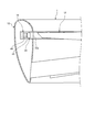
- FIG. 1 is a cross-sectional view of a motor-integrated fan according to the first embodiment.
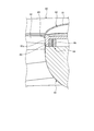
- FIG. 2 is a partial cross-sectional view of a modified example of the motor-integrated fan according to the first embodiment.
- FIG. 3 is an explanatory diagram of an example of the duct of the motor-integrated fan according to the first embodiment.
- FIG. 4 is an explanatory diagram of an example of the cooling unit of the motor-integrated fan according to the first embodiment.
- FIG. 5 is an explanatory diagram of an example of the cooling unit of the motor-integrated fan according to the first embodiment.
- FIG. 6 is an explanatory diagram of an example of the cooling unit of the motor-integrated fan according to the first embodiment.
- FIG. 1 is a cross-sectional view of a motor-integrated fan according to the first embodiment.
- FIG. 2 is a partial cross-sectional view of a modified example of the motor-integrated fan according to the first embodiment.
- FIG. 3 is an explanatory diagram of an example
- FIG. 7 is an explanatory diagram of an example of the air intake port of the motor-integrated fan according to the first embodiment.
- FIG. 8 is an explanatory diagram of an example of the air intake port of the motor-integrated fan according to the first embodiment.
- FIG. 9 is an explanatory diagram of an example of the air outlet of the motor-integrated fan according to the first embodiment.
- FIG. 10 is an explanatory diagram of an example of the air intake port and the air exhaust port of the motor-integrated fan according to the first embodiment.
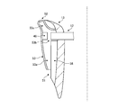
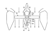
- FIG. 11 is a sectional view of the motor-integrated fan according to the second embodiment.
- FIG. 12 is a partial cross-sectional view of a modified example of the motor-integrated fan according to the second embodiment.
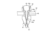
- FIG. 13 is an explanatory diagram of an example of the shaft portion of the motor-integrated fan according to the second embodiment.
- FIG. 14 is an explanatory diagram of an example of a cooling unit of the motor-integrated fan according to the second embodiment.
- FIG. 15 is an explanatory diagram of an example of an air intake port and an air exhaust port of the motor-integrated fan according to the second embodiment.
- the motor-integrated fan 1 according to the first embodiment is an axial fan.
- the motor-integrated fan 1 takes in air from the suction port and blows air from the air outlet to generate a propulsive force.
- the motor-integrated fan 1 is provided, for example, in a vertical take-off and landing aircraft such as a helicopter or a drone.
- the motor-integrated fan 1 provided in the vertical takeoff and landing aircraft generates a propulsive force for levitating the airframe and a propulsive force for controlling the attitude of the airframe.
- the motor-integrated fan 1 may be applied to an air cushion vehicle such as a hovercraft.
- FIG. 1 is a cross-sectional view of a motor-integrated fan according to the first embodiment.
- FIG. 2 is an explanatory diagram of a duct of the motor-integrated fan according to the first embodiment.
- the motor-integrated fan 1 is called a duct type propeller or a ducted fan.
- the motor-integrated fan 1 is used, for example, in a horizontal state with the axial direction being the vertical direction, takes in air from the upper side in the vertical direction, and blows air to the lower side in the vertical direction.
- the motor-integrated fan 1 may be used in a vertical state in which the axial direction is horizontal.
- the motor-integrated fan 1 is a fan in which one motor is integrally provided, and includes a shaft portion 11, a rotating portion 12, an outer peripheral portion 13, a motor 14, a rolling bearing 15, a current plate 16, and cooling.
- the unit 17, an aerodynamic device 18, a thermoelectric conversion element 19, and a control unit 20 are provided.
- the shaft 11 is provided at the center of the rotating shaft I and serves as a support system (fixed side). Since the axial direction of the rotary shaft I is the vertical direction in FIG. 1, the air flow direction is along the axial direction of the rotary shaft I.
- the shaft portion 11 includes a shaft-side fitting portion 25, which is a portion provided on the upstream side in the axial direction of the rotation shaft I, and a shaft main body 26, which is a portion provided on the downstream side of the shaft-side fitting portion 25.
- the shaft-side fitting portion 25 is fitted with the hub 31 of the rotating portion 12, which will be described later.
- the shaft-side fitting portion 25 has a cylindrical shape and is provided so as to project in the axial direction from the upstream end surface of the shaft body 26.
- the shaft-side fitting portion 25 has a cylindrical space formed on the center side of the rotating shaft I. A part of the hub 31 of the rotating unit 12 is inserted into this space.
- the outer peripheral side of the shaft side fitting portion 25 is surrounded by a part of the hub 31 of the rotating portion 12.
- the shaft body 26 has a substantially conical shape that tapers from the upstream side to the downstream side in the axial direction.
- the outer peripheral surface of the shaft main body 26 is a surface from the outer side to the inner side in the radial direction from the upstream side to the downstream side in the axial direction.
- the device is, for example, a control device, a camera, or the like.
- an outer end surface of the rectifying plate 16, which will be described later, is connected to the outer peripheral surface of the shaft body 26.
- the rotating unit 12 is a rotating system (rotating side) that rotates around the shaft 11.
- the rotating portion 12 is provided on the inflow side where air flows in with respect to the shaft portion 11 in the axial direction of the rotation shaft I.
- the rotating unit 12 includes a hub 31, a plurality of blades 32, and a rotation support ring 33.
- the hub 31 is provided on the upstream side of the shaft portion 11 in the axial direction, and is rotatably fitted to the shaft-side fitting portion 25.
- the hub 31 constitutes a part of the shaft portion 11.
- the hub 31 has a hub main body 35 that is a portion provided on the upstream side in the axial direction, and a hub side fitting portion 36 that is a portion provided on the downstream side of the hub main body 35.
- the hub body 35 is formed into a hemispherical surface whose upstream end surface has a predetermined radius of curvature.
- the hub-side fitting portion 36 has a shape complementary to the shaft-side fitting portion 25.
- the hub-side fitting portion 36 includes a central shaft 36a provided at the center of the rotating shaft and a cylindrical portion 36b having a cylindrical shape provided on the outer peripheral side of the central shaft 36a.
- the central shaft 36a is inserted into the space at the center of the rotation shaft of the shaft-side fitting portion 25.
- the cylindrical portion 36b is provided so as to project in the axial direction from the end surface on the downstream side of the hub body 35.
- the cylindrical portion 36b is arranged so as to surround the outer periphery of the shaft-side fitting portion 25.
- the rolling bearing 15 is provided between the inner peripheral surface of the shaft-side fitting portion 25 and the outer peripheral surface of the central shaft 36a of the hub 31.
- the surface from the end surface of the hub body 35, through the outer peripheral surface of the cylindrical portion 36b, to the outer peripheral surface of the shaft body 26 is a smooth surface without steps.
- the plurality of blades 32 are provided so as to extend from the hub 31 toward the outer side in the radial direction, and are arranged side by side at predetermined intervals in the circumferential direction.
- Each blade 32 has a wing shape.
- the surface formed by rotating the plurality of blades 32 by the end portion on the inflow side orthogonal to the axial direction of the rotation axis I is the rotation surface P.
- the rotation support ring 33 is formed in an annular shape around the rotation axis I.
- the rotation support ring 33 is connected to the outer peripheral side of the plurality of blades 32 in the radial direction of the rotation axis I.
- the rotation support ring 33 includes an inner ring portion 33a that is a portion that forms a part of the inner peripheral surface of the outer peripheral portion 13 described below, and a flange portion 33b that is a portion that is provided so as to project radially outward of the inner ring portion 33a. Is included.
- the inner peripheral surface of the inner ring portion 33 a on the radially inner side is a part of the inner peripheral surface of the outer peripheral portion 13.
- each blade 32 is joined to the inner peripheral surface of the inner ring portion 33a by welding or the like.
- the flange portion 33b is provided on the upstream side in the axial direction of the inner ring portion 33a.
- the flange portion 33b holds a permanent magnet 45 of the motor 14, which will be described later.
- the flange portion 33b holds the permanent magnet 45 so that the permanent magnet 45 faces the downstream side in the axial direction.
- the hub 12, the plurality of blades 32, and the rotation support ring 33 are integrally joined to the rotating portion 12 and rotate about the hub 31.
- the outer peripheral portion 13 is provided on the outer side in the radial direction of the shaft portion 11 and serves as a support system (fixed side).
- the outer peripheral portion 13 is formed in an annular shape and serves as a duct that generates thrust by the rotation of the rotating portion 12.
- the upstream side opening is a suction port 38 and the downstream side opening is a blowout port 39 in the axial direction of the rotating shaft I.
- the duct 13 has an annular internal space formed therein for accommodating a flange portion 33b of the rotation support ring 33 of the rotating portion 12 and a coil 46 of the motor 14, which will be described later.
- the duct 13 holds a coil 46 provided inside the duct 13 at a position facing the permanent magnet 45 held by the rotating unit 12.
- the duct 13 sucks air from the suction port 38 and blows the sucked air from the blow-out port 39 by the rotation of the rotating portion 12, thereby generating thrust.
- the motor 14 is an outer peripheral drive motor that rotates the rotating part 12 by applying power from the duct 13 side to the rotating part 12.
- the motor 14 has a rotor-side magnet provided on the rotating unit 12 side and a stator-side magnet provided on the duct 13 side.
- the rotor-side magnet is the permanent magnet 45
- the stator-side magnet is the coil (electromagnet) 46.
- the coil 46 is provided in the support system to simplify the configuration related to the wiring around the coil 46, but the configuration is not particularly limited to this.
- the rotor side magnet may be a coil
- the stator side magnet may be a permanent magnet 45.
- the permanent magnet 45 is provided so as to be held by the flange portion 33b of the rotation support ring 33, and is arranged in an annular shape in the circumferential direction. Further, the permanent magnet 45 is configured such that the positive electrode and the negative electrode are alternately arranged at predetermined intervals in the circumferential direction. The permanent magnet 45 is provided at a position facing the coil 46 in the axial direction of the rotation axis I.
- the coil 46 is provided while being held inside the duct 13, a plurality of coils 46 are provided facing each pole of the permanent magnet 45, and are arranged side by side in the circumferential direction.
- the coil 46 is provided at a position facing the permanent magnet 45 held by the rotating portion 12 in the axial direction of the rotating shaft I. That is, the permanent magnet 45 and the coil 46 are arranged axially so as to face each other in the axial direction of the rotation axis I.
- FIG. 2 is a partial cross-sectional view of a modified example of the motor-integrated fan according to the first embodiment.
- the permanent magnet 45 and the coil 46 are arranged in a radial arrangement in which they are arranged to face each other in the radial direction of the rotation axis I.
- the rotary support ring 33 that holds the permanent magnet 45 has a structure in which the flange portion 33b is omitted, and holds the permanent magnet 45 on the outer peripheral side of the inner ring portion 33a.
- the permanent magnet 45 is held and provided on the outer peripheral side of the inner ring portion 33a of the rotation support ring 33, and is arranged in an annular shape in the circumferential direction.
- the permanent magnet 45 is provided at a position facing the coil 46 in the radial direction of the rotation axis I.
- the coil 46 is provided while being held inside the duct 13, a plurality of coils 46 are provided facing each pole of the permanent magnet 45, and are arranged side by side in the circumferential direction.
- the coil 46 is provided at a position facing the permanent magnet 45 held by the rotating portion 12 in the radial direction of the rotating shaft I. In this way, the permanent magnet 45 and the coil 46 may be arranged radially opposite to each other in the radial direction of the rotation axis I.
- the rolling bearing 15 is provided between the inner peripheral surface of the shaft-side fitting portion 25 of the shaft portion 11 and the outer peripheral surface of the central shaft 36a of the hub 31 of the rotating portion 12.
- the rolling bearing 15 connects the shaft portion 11 and the rotation portion 12 while allowing the rotation portion 12 to rotate with respect to the shaft portion 11.
- the rolling bearing 15 is, for example, a ball bearing or the like.
- the current plate 16 is provided by connecting the shaft portion 11 and the duct 13.
- the current plate 16 is provided on the downstream side of the rotating unit 12 in the axial direction of the rotating shaft I. That is, the current plate 16 is provided at the position of the downstream side portion 43 of the duct 13 in the axial direction.
- the straightening vanes 16 are arranged side by side in the circumferential direction of the rotation axis I. Further, the straightening vane 16 has a streamlined shape such as a blade shape, and straightens the air flowing from the rotating portion 12.
- the shape of the current plate 16 is not limited to the blade shape, and may be a flat plate shape.
- the cooling unit 17 cools a heat generating unit that generates heat by the operation of the motor 14 with cooling air.
- the heat generating portion is, for example, the coil 46 of the motor 14. It should be noted that in FIG. 2, the coil 46 is shown in a simplified manner, and therefore the position is different from the actual position. Since the coil 46 is provided inside the duct 13, the cooling unit 17 is provided in the duct 13 to cool the coil 46.
- the cooling unit 17 includes an air intake port 51 that takes in cooling air, an air exhaust port 52 that exhausts the cooling air, and a cooling flow path 53 that extends from the air intake port 51 to the air exhaust port 52.
- the air intake 51 is formed on the outer peripheral surface of the duct 13.
- the air intake port 51 is provided on the downstream side (on the blowout port 39 side) of the rotating unit 12 in the axial direction of the rotating shaft I.
- the pressure around the portion where the air intake port 51 is formed is atmospheric pressure.
- the air outlet 52 is formed on the inner peripheral surface of the duct.
- the air outlet 52 is provided on the upstream side of the rotating unit 12 in the flow direction of the air flowing from the suction port 38 toward the air outlet 39.
- the pressure around the portion where the air outlet 52 is formed is more negative than the pressure around the air inlet 51. That is, the pressure around the portion where the air outlet 52 is formed is smaller than the atmospheric pressure.
- the air intake port 51 is formed to have a larger opening area than the air exhaust port 52.
- the air outlet 52 is formed so that the opening area is smaller than that of the air inlet 51.
- the cooling flow path 53 includes a flow path 53a extending from the air intake port 51 to the coil 46, an internal space 53b of the duct 13 in which the coil 46 is arranged, and a flow path 53c extending from the coil 46 to the air discharge port 52. Including.
- the cooling flow passage 53 guides the air taken in from the air intake port 51 to the internal space 53b as cooling air, introduces the cooling air into the internal space 53b, and at the same time, cools the cooling air in the internal space 53b to the air exhaust port. I will guide you to 52.
- Such a cooling unit 17 takes in air from the air intake port 51, blows cooling air to the coil 46 in the internal space 53b, and discharges the cooling air blown to the coil 46 from the air exhaust port 52. The heat of the coil 46 is removed.
- the aerodynamic device 18 gives a flow to the staying cooling air.
- the aerodynamic device 18 is a plasma actuator, a synthetic jet, a vortex generator, or the like.
- the aerodynamic device 18 is provided in the air intake port 51, the air exhaust port 52, and the cooling flow path 53.
- the aerodynamic device 18 is provided in the air intake port 51, the air exhaust port 52 and the cooling flow passage 53, but at least one of the air intake port 51, the air exhaust port 52 and the cooling flow passage 53 is provided. It may be provided in the crab and is not particularly limited.
- a plasma actuator is applied to the aerodynamic device 18 provided in the air intake port 51, and air is provided so as to flow toward the air intake port 51.
- the aerodynamic device 18 is provided on the outer peripheral surface of the duct 13 near the air intake port 51.
- the aerodynamic device 18 provided in the air intake 51 may be provided in the flow passage 53a of the cooling flow passage 53 near the air intake 51.
- the plasma device is applied to the aerodynamic device 18 provided in the air discharge port 52, and the air is discharged from the air discharge port 52.
- the aerodynamic device 18 is provided on the inner peripheral surface of the duct 13 near the air outlet 52.
- the aerodynamic device 18 provided in the air outlet 52 may be provided in the flow passage 53c of the cooling flow passage 53 near the air outlet 52.
- the aerodynamic device 18 provided in the internal space 53b for example, a plasma actuator and a synthetic jet are applied, and the aerodynamic device 18 is provided so that cooling air flows from the flow passage 53a to the flow passage 53c.
- the aerodynamic device 18 is provided on the inner surface of the internal space and at the stagnation point of the cooling air staying in the internal space.
- the thermoelectric conversion element 19 is provided in the duct 13 and uses the heat generated from the coil 46 to generate electric power.
- the thermoelectric conversion element 19 converts the thermal energy from the coil 46 into electric energy and supplies electric power to the aerodynamic device 18.
- the thermoelectric conversion element 19 has a high temperature portion provided on the coil 46 side and a low temperature portion provided at a portion having a lower temperature than the high temperature portion. Specifically, in the thermoelectric conversion element 19, the low temperature portion is provided at the outer peripheral surface of the duct 13, and the high temperature portion is provided so as to face the coil 46.
- a heat transfer member 55 is provided between the high temperature part and the coil 46, and heat of the coil 46 is input to the high temperature part of the thermoelectric conversion element 19 via the heat transfer member 55.
- the thermoelectric conversion element 19 may be configured to output the generated power to the control unit 20, and in this case, the control unit 20 may supply the power to the aerodynamic device 18.
- the control unit 20 is connected to each unit of the motor-integrated fan 1 and controls each unit to control the motor-integrated fan 1.
- the control unit 20 is connected to the coil 46.
- the control unit 20 controls the rotation of the rotating unit 12 by controlling the magnetic field of the coil 46.
- the control unit 20 is also connected to the aerodynamic device 18.
- the control unit 20 controls the operation of the aerodynamic device 18.
- the rotating portion 12 is rotated by applying power from the duct 13 side to the rotating portion 12 by the magnetic field by the motor 14.
- the motor-integrated fan 1 sucks air from the suction port 38 and blows air toward the air outlet 39.
- the air blown out from the rotating portion 12 flows along the inner peripheral surface of the duct 13 to generate thrust.
- the cooling unit 17 takes in air from the air inlet port 51 and uses the taken-in air as cooling air.
- Distribute 53 The cooling air flowing through the cooling passage 53 hits the coil 46 in the internal space 53b.
- the cooling air blown onto the coil 46 is discharged from the air discharge port 52. Thereby, the cooling unit 17 removes heat from the coil 46 with the cooling air.
- FIGS. 4 to 6 are explanatory views of an example of the cooling unit of the motor-integrated fan according to the first embodiment.
- the cooling flow path 53 is linearly formed from the air intake port 51 to the air discharge port 52. Further, the linear cooling flow passage 53 is formed so as to intersect the coil 46 in the internal space 53b.
- the air intake port 51 shown in FIG. 3 is formed on the inner peripheral surface of the duct 13.
- the air intake port 51 is provided on the downstream side of the rotating unit 12 in the flow direction of the air flowing from the suction port 38 toward the air outlet 39.
- the pressure around the portion where the air intake port 51 is formed is more positive than the pressure around the air discharge port 52. That is, the pressure around the portion where the air intake port 51 is formed is higher than the pressure around the air discharge port 52.
- the air outlet 52 has a negative pressure compared to the air inlet 51. Therefore, the cooling unit 17 takes in air from the air intake port 51 and causes the taken-in air as cooling air to flow through the cooling flow path 53.
- the air outlet 52 shown in FIG. 3 is formed on the outer peripheral surface of the duct 13.
- the air outlet 52 is provided closer to the suction port 38 than the air inlet 51.
- the pressure around the portion where the air outlet 52 is formed is more negative than the pressure around the air inlet 51. That is, the pressure around the portion where the air discharge port 52 is formed is smaller than the pressure around the air intake port 51.
- the air exhaust port 52 has a negative pressure compared to the air intake port 51. Therefore, the cooling unit 17 takes in air from the air intake port 51 and causes the taken-in air as cooling air to flow through the cooling flow path 53.
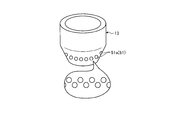
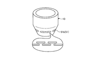
- FIGS. 7 and 8 are explanatory diagrams of an example of the air intake port of the motor-integrated fan according to the first embodiment.
- the air intake port 51 shown in FIG. 7 is configured to include a plurality of holes 51a.
- the holes 51a are formed on the outer peripheral surface of the duct 13 and are formed side by side in the circumferential direction.
- the holes 51a are formed in one row or a plurality of rows in the circumferential direction.
- the plurality of holes 51a are arranged in a staggered pattern along the circumferential direction.
- the air intake port 51 shown in FIG. 8 is configured to include a slit 51b extending in the longitudinal direction.
- the slit 51b is formed on the outer peripheral surface of the duct 13 and is formed such that the circumferential direction is the longitudinal direction.
- the slits 51b are formed side by side in the circumferential direction.
- the slits 51b are formed in one row or a plurality of rows in the circumferential direction. When the slits 51b are formed in a plurality of rows in the circumferential direction, the plurality of slits 51b are arranged in a staggered pattern along the circumferential direction.
- FIG. 9 is an explanatory diagram of an example of the air outlet of the motor-integrated fan according to the first embodiment.
- the air outlet 52 shown in FIG. 9 is provided so as to protrude from the surface of the portion where the air outlet 52 is formed. That is, when the air outlet 52 is formed on the inner peripheral surface of the duct 13, the air outlet 52 is formed so as to protrude from the inner peripheral surface of the duct 13. When the air outlet 52 is formed on the outer peripheral surface of the duct 13, the air outlet 52 is formed so as to protrude from the outer peripheral surface of the duct 13.
- the air outlet 52 may be, for example, a nozzle type, a line type, or an anemo type, and the shape is not particularly limited.
- the cooling unit 17 shown in FIG. 10 has a configuration in which the cooling flow path 53 is not linear.
- the cooling flow path 53 is formed so as to curve from the air intake port 51 toward the air discharge port 52.
- the curved cooling passage 53 is provided with a ventilation guide 58 for guiding the cooling air taken in from the air intake 51.
- the ventilation guide 58 guides the cooling air from the air intake 51 to the coil 46, and also guides the cooling air from the coil 46 to the air outlet 52.
- the cooling air is taken from the air intake port 51 by using the negative pressure of the air exhaust port 52 with respect to the air intake port 51, and passes through the coil 46 that is the heat generating portion.
- the subsequent cooling air can be discharged from the air outlet 52. Therefore, the heat of the coil 46 can be suitably removed by the cooling air.
- the negative pressure of the air outlet 52 with respect to the air inlet 51 is used, it is possible to suppress the reduction in fan performance of the motor-integrated fan 1.
- the cooling unit 17 illustrated in FIG. 2 takes in air from the outer peripheral surface of the duct 13 that is at atmospheric pressure, and the cooling unit 17 of the rotating unit 12 has a low pressure. Air can be discharged from the inner peripheral surface of the duct 13 on the upstream side. Therefore, since the air intake port 51 and the air exhaust port 52 can be provided at the position where the pressure difference between the air intake port 51 and the air exhaust port 52 becomes large, the cooling air can be suitably used in the cooling flow passage 53. It can be distributed.
- the cooling unit 17 shown in FIG. 4 takes in air from the inner peripheral surface of the duct 13 and discharges air from the inner peripheral surface of the duct 13. be able to. Therefore, even when it is difficult to provide the air intake port 51 and the air exhaust port 52 on the outer peripheral surface of the duct 13, a pressure difference is created between the air intake port 51 and the air exhaust port 52. Since it can be generated, the cooling air can be suitably circulated in the cooling channel 53.
- the cooling unit 17 illustrated in FIG. 5 can take in air from the outer peripheral surface of the duct 13 and discharge air from the outer peripheral surface of the duct 13. it can. Therefore, even if it is difficult to provide the air intake port 51 and the air exhaust port 52 on the inner peripheral surface of the duct 13, the pressure difference between the air intake port 51 and the air exhaust port 52 is reduced. Therefore, the cooling air can be appropriately circulated in the cooling flow path 53.
- the cooling flow passage 53 by making the cooling flow passage 53 linear, it is possible to suppress the pressure loss in the cooling flow passage 53, so that the cooling air flow in the cooling flow passage 53 is reduced. Can be distributed more preferably.
- the opening area of the air intake port 51 compared to the air exhaust port 52 by increasing the opening area of the air intake port 51 compared to the air exhaust port 52, a large amount of air can be taken in from the air intake port 51, and the air exhaust port The flow velocity of the cooling air at 52 can be increased.
- the plurality of holes 51a and provide the air intake port 51 it is possible to form the plurality of holes 51a and provide the air intake port 51, or to form the slit 51b and provide the air intake port 51.
- the air discharge port 52 is provided so as to project from the inner peripheral surface or the outer peripheral surface of the duct 13, thereby increasing the flow velocity of the air in the air discharge port 52. Therefore, the negative pressure of the air outlet 52 can be increased.
- the cooling air is directed from the air intake port 51 to the coil 46 and the coil 46. It is possible to properly guide the air from the toward the air outlet 52. Therefore, the cooling air can be more preferably circulated in the cooling channel 53.
- the cooling air can be appropriately flowed, so that the cooling efficiency by the cooling air can be improved.
- the heat of the coil 46 can be used to generate electric power by the thermoelectric conversion element 19 and supply the electric power to the aerodynamic device 18. Therefore, it is not necessary to provide an external power source, and the configuration of the motor-integrated fan 1 can be simplified.
- the vertical take-off and landing aircraft in which the motor-integrated fan 1 is mounted on the airframe may use the motor-integrated fan 1 in which the coil 46 is deheated and the reduction in fan performance is suppressed. Therefore, the thrust by the motor-integrated fan 1 can be appropriately obtained.
- the coil 46 of the motor 14 is applied as the heat generating portion, but other than the coil 46 may be used, and the heat generating portion generated by operating the motor 14 is not particularly limited.
- FIG. 11 is an explanatory diagram of an example of the shaft portion of the motor-integrated fan according to the second embodiment.
- FIG. 12 is a partial cross-sectional view of a modified example of the motor-integrated fan according to the second embodiment.
- FIG. 13 is an explanatory diagram of an example of the shaft portion of the motor-integrated fan according to the second embodiment.
- FIG. 14 is an explanatory diagram of an example of a cooling unit of the motor-integrated fan according to the second embodiment.
- FIG. 15 is an explanatory diagram of an example of the air intake port and the air exhaust port of the motor-integrated fan according to the second embodiment.
- the motor-integrated fan 1 of the first embodiment is a motor in which the motor 14 is driven on the outer circumference
- the motor-integrated fan 60 of the second embodiment is a motor in which the motor 64 is driven in the inner circumference. Therefore, in the motor-integrated fan 60 of the second embodiment, the coil 46 of the motor 64 that is driven in the inner circumference is cooled by the cooling unit 67.
- the motor-integrated fan 60 includes a shaft portion 61, a rotating portion 62, a duct 63, a motor 64, a rolling bearing 65, a rectifying plate 66, a cooling portion 67, an aerodynamic device 68, and a thermoelectric device.
- the conversion element 69 and the control unit 70 are provided. Since the rolling bearing 65, the current plate 66, the aerodynamic device 68, the thermoelectric conversion element 69, and the control unit 70 are almost the same as those in the first embodiment, the description thereof will be omitted.
- the shaft portion 61 is provided at the center of the rotating shaft I and serves as a support system (fixed side).
- the shaft portion 61 includes a shaft-side fitting portion 75, which is a portion provided on the upstream side in the axial direction of the rotation shaft I, and a shaft main body 76, which is a portion provided on the downstream side of the shaft-side fitting portion 75.
- the shaft side fitting portion 75 is fitted with a rotation support ring 83 of the rotating portion 62 described later.
- the shaft-side fitting portion 75 has a cylindrical shape, and is provided on the upstream end surface of the shaft body 76 so as to project from the center of the rotation shaft I to the upstream side in the axial direction.
- the outer peripheral side of the shaft-side fitting portion 75 is surrounded by the rotation support ring 83 of the rotating portion 62.
- the shaft body 76 has a hemispherical shape that is convex from the upstream side to the downstream side in the axial direction. For this reason, the outer peripheral surface of the shaft main body 76 is a surface from the outer side to the inner side in the radial direction from the upstream side to the downstream side in the axial direction. Further, the shaft main body 76 holds the coil 46 at a position on the outer peripheral side of the shaft side fitting portion 75 on the end face on the upstream side in the axial direction. Note that, as in the first embodiment, an internal space in which a device can be installed may be formed inside the shaft body 76.
- the rotating part 62 is a rotating system (rotating side) that rotates around the shaft part 61.
- the rotating portion 62 is provided on the inflow side where air flows in with respect to the shaft portion 61 in the axial direction of the rotating shaft I.
- the rotating portion 62 has a hub 81, a plurality of blades 82, and a rotation support ring 83.
- the hub 81 is provided on the upstream side in the axial direction of the shaft portion 61 and constitutes a part of the shaft portion 61.
- the hub 31 is formed into a spherical surface whose upstream end surface has a predetermined radius of curvature.
- the rotation support ring 83 is provided on the downstream side of the hub 81 in the axial direction and is integrated with the hub 81.
- the rotation support ring 83 is rotatably fitted in the shaft-side fitting portion 75.
- the rotation support ring 83 is formed in an annular shape around the rotation axis I.
- the rotation support ring 83 includes an outer ring portion 83a provided on the outer side in the radial direction, a flange portion 83b that is a portion provided to project radially inward of the outer ring portion 83a, and a portion provided on the inner side in the radial direction of the flange portion 83b.
- the outer ring portion 83a has a cylindrical shape, and has a smooth outer peripheral surface having no step with respect to the outer peripheral surface of the shaft portion 61.
- the radially inner end of each blade 82 is joined to the outer peripheral surface of the outer ring portion 83a by welding or the like.
- the flange portion 83b is provided on the upstream side in the axial direction of the outer ring portion 83a.
- the flange portion 83b holds the permanent magnet 45 of the motor 64, which will be described later.
- the flange portion 83b holds the permanent magnet 45 so that the permanent magnet 45 faces the downstream side in the axial direction.
- the inner ring portion 83c has a cylindrical shape and is provided so as to surround the shaft-side fitting portion 75.
- the inner peripheral surface of the inner ring portion 83c faces the outer peripheral surface of the shaft-side fitting portion 75.
- the rolling bearing 65 is provided between the outer peripheral surface of the shaft side fitting portion 75 of the shaft portion 61 and the inner peripheral surface of the inner ring portion 83 c of the rotation support ring 83.
- the plurality of blades 82 are connected to the outer peripheral surface of the rotation support ring 83.
- the plurality of blades 82 are provided so as to extend outward from the rotation support ring 83 in the radial direction, and are arranged side by side at predetermined intervals in the circumferential direction.
- Each blade 82 has a wing shape.
- Each blade 82 has its radially inner end connected to the outer peripheral surface of the rotation support ring 83, while its radially outer end is a free end.
- the duct 63 is provided on the outside in the radial direction of the shaft portion 11 and serves as a support system (fixed side).
- the duct 63 is formed in an annular shape and serves as a duct that generates thrust by the rotation of the rotating portion 62.
- the opening on the upstream side is the suction port 38 and the opening on the downstream side is the air outlet 39.
- the motor 64 is an inner peripheral drive motor that rotates the rotating portion 62 by applying power from the shaft portion 61 side to the rotating portion 62.
- the motor 64 has a rotor-side magnet provided on the rotating portion 62 side and a stator-side magnet provided on the shaft portion 61 side.
- the rotor-side magnet is the permanent magnet 45
- the stator-side magnet is the coil (electromagnet) 46.
- the coil 46 is provided in the support system to simplify the configuration related to the wiring around the coil 46, but the configuration is not limited to this.
- the rotor side magnet may be a coil
- the stator side magnet may be a permanent magnet 45.
- the permanent magnet 45 is provided so as to be held by the flange portion 83b of the rotation support ring 83, and is arranged in an annular shape in the circumferential direction.
- the rest of the configuration of the permanent magnet 45 is the same as that of the first embodiment, and the description thereof is omitted.
- the coil 46 is provided so as to be held on the upstream end surface of the shaft body 76 of the shaft portion 61, and a plurality of coils 46 are provided so as to face each pole of the permanent magnet 45 and are arranged side by side in the circumferential direction. Since the other configurations of the coil 46 are the same as those in the first embodiment, the description thereof will be omitted.
- the permanent magnet 45 and the coil 46 are arranged axially so as to face each other in the axial direction of the rotation axis I, but a modification shown in FIG. 12 may be used.
- the permanent magnet 45 and the coil 46 are arranged in a radial arrangement in which they are arranged to face each other in the radial direction of the rotation axis I.
- the permanent magnet 45 is held and provided on the outer peripheral side of the inner ring portion 83c of the rotation support ring 83, and is arranged in an annular shape in the circumferential direction.
- the permanent magnet 45 is provided at a position facing the coil 46 in the radial direction of the rotation axis I.
- the coils 46 are held and provided inside the shaft portion 61, and a plurality of coils 46 are provided so as to face each pole of the permanent magnet 45 and are arranged side by side in the circumferential direction.
- the coil 46 is provided at a position facing the permanent magnet 45 held by the rotating portion 62 in the radial direction of the rotating shaft I. In this way, the permanent magnet 45 and the coil 46 may be arranged radially opposite to each other in the radial direction of the rotation axis I.
- the cooling unit 67 cools a heat generating section that generates heat due to the operation of the motor 64 with cooling air.
- the heat generating portion is, for example, the coil 46 of the motor 64. Note that, in FIG. 13, the coil 46 is illustrated in a simplified manner, and therefore, the actual position is different. Since the coil 46 is provided on the upstream end surface of the shaft body 76 of the shaft portion 61, the cooling portion 67 is provided at a portion from the shaft portion 61 to the hub 81 of the rotating portion 62 in order to cool the coil 46. It is provided.
- the cooling unit 67 includes an air intake port 91 that takes in cooling air, an air exhaust port 92 that exhausts the cooling air, and a cooling flow path 93 that extends from the air intake port 91 to the air exhaust port 92.
- the air intake 91 is formed on the outer peripheral surface of the shaft portion 61.
- the air intake port 91 is provided on the downstream side (on the blowout port 39 side) of the rotating portion 62 in the axial direction of the rotating shaft I.
- the air outlet 92 is formed on the outer peripheral surface of the hub 81 that constitutes a part of the shaft 61.
- the air discharge port 92 is provided on the upstream side of the rotating portion 62 in the flow direction of the air flowing from the suction port 38 toward the air outlet 39.
- the pressure around the portion where the air discharge port 92 is formed is more negative than the pressure around the air intake port 91.
- the cooling flow passage 93 has a flow passage 93a extending from the air intake 91 to the coil 46, an internal space 93b of the shaft portion 61 in which the coil 46 is arranged, a flow passage 93c extending from the coil 46 to the air discharge port 92, and including.
- the cooling flow passage 93 guides the air taken in from the air intake 91 to the internal space 93b as cooling air, introduces the cooling air into the internal space 93b, and at the same time, cools the cooling air in the internal space 93b to the air exhaust port. I will guide you to 92.
- Such a cooling unit 67 takes in air from the air intake port 91, blows cooling air to the coil 46 in the internal space 93b, and discharges the cooling air blown to the coil 46 from the air exhaust port 92. The heat of the coil 46 is removed.
- the rotating portion 62 is rotated by applying power from the magnetic field to the rotating portion 62 from the shaft portion 61 side by the motor 64.
- the motor-integrated fan 60 sucks air from the suction port 38 and blows air toward the air outlet 39.
- the air blown out from the rotating portion 62 flows along the inner peripheral surface of the duct 63 to generate thrust.
- the cooling unit 67 takes in air from the air intake port 91 and causes the taken-in air as cooling air to flow through the cooling flow passage 93.
- the cooling air flowing through the cooling passage 93 blows against the coil 46 in the internal space 93b.
- the cooling air blown against the coil 46 is discharged from the air discharge port 92.
- the cooling unit 67 removes heat from the coil 46 with the cooling air.
- the cooling flow path 93 is linearly formed from the air intake port 91 to the air discharge port 92. Further, the linear cooling flow passage 93 is formed so as to intersect with the coil 46 in the internal space 93b. Further, a plurality of cooling channels 93 are formed on the shaft portion 61, and the plurality of cooling channels 93 are formed so as to intersect each other in the channel 93a. At this time, the plurality of cooling flow paths 93 may be configured to communicate with each other in the intersecting flow paths 93a, or may be configured to be non-communication (configuration not to communicate), and are not particularly limited.
- the cooling unit 67 shown in FIG. 15 has a configuration in which the cooling flow path 93 is not linear as shown in FIG.
- the cooling unit 67 shown in FIG. 15 is formed so that the cooling flow path 93 is curved from the air intake port 91 toward the air discharge port 92.
- the curved cooling passage 93 is provided with a ventilation guide 95 for guiding the cooling air taken in from the air intake 91.
- the ventilation guide 95 guides the cooling air from the air intake port 91 to the coil 46 and guides the cooling air from the coil 46 to the air discharge port 92.
- the negative pressure of the air exhaust port 92 with respect to the air intake port 91 is used to supply the cooling air from the air intake port 91.
- the cooling air that has been taken in and passed through the coil 46 that is the heat generating portion can be discharged from the air discharge port 92. Therefore, the heat of the coil 46 can be suitably removed by the cooling air.
- the negative pressure of the air exhaust port 92 with respect to the air intake port 91 is used, it is possible to suppress the reduction of the fan performance of the motor-integrated fan 60.
- cooling flow passage 93 is linear, pressure loss in the cooling flow passage 93 can be suppressed. Can be distributed more preferably.
- the cooling air is directed from the air intake port 91 to the coil 46, and the coil 46. It is possible to properly guide from the air outlet toward the air outlet 92. Therefore, the cooling air can be more preferably circulated in the cooling flow passage 93.
Landscapes
- Engineering & Computer Science (AREA)
- Mechanical Engineering (AREA)
- Aviation & Aerospace Engineering (AREA)
- Combustion & Propulsion (AREA)
- Chemical & Material Sciences (AREA)
- General Engineering & Computer Science (AREA)
- Power Engineering (AREA)
- Physics & Mathematics (AREA)
- Thermal Sciences (AREA)
- Plasma & Fusion (AREA)
- Motor Or Generator Cooling System (AREA)
- Structures Of Non-Positive Displacement Pumps (AREA)
- Connection Of Motors, Electrical Generators, Mechanical Devices, And The Like (AREA)
Abstract
La présente invention concerne un ventilateur intégré à un moteur qui aspire de l'air à travers un orifice d'aspiration et souffle l'air aspiré à travers un orifice de soufflage : le ventilateur intégré à un moteur comprenant une partie d'arbre disposée au centre d'un arbre de rotation, une partie de rotation (12) qui tourne autour de la partie d'arbre, un conduit (13) disposé sur la circonférence extérieure de la partie d'arbre, un moteur (14) qui amène la partie de rotation (12) à tourner, une bobine (46) qui émet de la chaleur en raison du fonctionnement du moteur (14), et une unité de refroidissement (17) qui refroidit la bobine (46) à l'aide d'air de refroidissement ; l'unité de refroidissement (17) comprenant un orifice d'arrivée d'air (51) qui aspire l'air de refroidissement, un orifice d'évacuation d'air (52) qui évacue l'air de refroidissement, et un trajet d'écoulement de refroidissement (53) s'étendant à partir de l'orifice d'arrivée d'air (51) par l'intermédiaire de la bobine (46) vers l'orifice d'évacuation d'air (52) ; et l'orifice d'évacuation d'air (52) étant disposé à une position dans laquelle la pression est plus négative qu'au niveau de l'orifice d'arrivée d'air (51).
Priority Applications (2)
| Application Number | Priority Date | Filing Date | Title |
|---|---|---|---|
| US17/312,592 US11851197B2 (en) | 2018-12-13 | 2019-12-10 | Motor-integrated fan, and vertical takeoff and landing craft |
| EP19897398.4A EP3878737A4 (fr) | 2019-12-10 | Ventilateur intégré à un moteur, et engin de décollage et d'atterrissage vertical |
Applications Claiming Priority (2)
| Application Number | Priority Date | Filing Date | Title |
|---|---|---|---|
| JP2018233717A JP7182449B2 (ja) | 2018-12-13 | 2018-12-13 | モータ一体型ファン及び垂直離着陸機 |
| JP2018-233717 | 2018-12-13 |
Publications (1)
| Publication Number | Publication Date |
|---|---|
| WO2020122056A1 true WO2020122056A1 (fr) | 2020-06-18 |
Family
ID=71077250
Family Applications (1)
| Application Number | Title | Priority Date | Filing Date |
|---|---|---|---|
| PCT/JP2019/048227 Ceased WO2020122056A1 (fr) | 2018-12-13 | 2019-12-10 | Ventilateur intégré à un moteur, et engin de décollage et d'atterrissage vertical |
Country Status (3)
| Country | Link |
|---|---|
| US (1) | US11851197B2 (fr) |
| JP (1) | JP7182449B2 (fr) |
| WO (1) | WO2020122056A1 (fr) |
Cited By (2)
| Publication number | Priority date | Publication date | Assignee | Title |
|---|---|---|---|---|
| WO2023056093A1 (fr) * | 2021-10-01 | 2023-04-06 | Cleo Robotics Inc. | Systèmes et procédés de commande de vol de véhicule aérien (av) |
| DE102023103681A1 (de) * | 2023-02-15 | 2024-08-22 | Rolls-Royce Deutschland Ltd & Co Kg | Antriebsvorrichtung und ein Senkrecht-Start- und -Landungsluftfahrzeug mit Antriebsvorrichtung |
Families Citing this family (8)
| Publication number | Priority date | Publication date | Assignee | Title |
|---|---|---|---|---|
| IT201900010008A1 (it) * | 2019-06-25 | 2020-12-25 | Interactive Fully Electrical Vehicles S R L | Aeromobile, in particolare drone a guida autonoma o aeromobile per mobilità aerea personale, con rotori propulsori a efficienza elevata |
| JP7413013B2 (ja) * | 2019-12-27 | 2024-01-15 | 三菱重工業株式会社 | モータ一体型流体機械、垂直離着陸機及びモータ一体型流体機械の設計方法 |
| JP7443272B2 (ja) * | 2021-01-18 | 2024-03-05 | 三菱重工業株式会社 | ファン装置及びこれを備えた航空機 |
| CN113443124B (zh) * | 2021-07-20 | 2022-08-19 | 北京理工大学 | 采用两级大小叶片的边界层吸入式推进器 |
| KR102650645B1 (ko) * | 2021-10-01 | 2024-03-28 | 주식회사 니나노컴퍼니 | 덕트 어셈블리 |
| US12503239B2 (en) * | 2022-04-27 | 2025-12-23 | Snap Inc. | UAV having shroud cooling openings |
| US12401312B2 (en) | 2023-03-23 | 2025-08-26 | Hamilton Sundstrand Corporation | Sensor-less temperature monitoring |
| US12448142B1 (en) | 2024-10-17 | 2025-10-21 | General Electric Company | Electric propulsion system for a flight vehicle |
Citations (7)
| Publication number | Priority date | Publication date | Assignee | Title |
|---|---|---|---|---|
| JPS55114399U (fr) * | 1979-02-07 | 1980-08-12 | ||
| US20080219844A1 (en) * | 2007-03-05 | 2008-09-11 | Xcelaero Corporation | Reverse flow cooling for fan motor |
| JP2010023825A (ja) | 2008-07-23 | 2010-02-04 | Honeywell Internatl Inc | ダクテッドファンuavの機器の冷却システムおよび冷却方法 |
| JP2013079606A (ja) * | 2011-10-04 | 2013-05-02 | Ebara Corp | トンネル用換気設備 |
| WO2015005776A1 (fr) * | 2013-07-09 | 2015-01-15 | Eco-Logical Enterprises B.V. | Dispositif rotatif, par exemple un échangeur aéraulique tel qu'un ventilateur, un propulseur ou un rotor sustentateur, une turbine hydraulique ou une turbine éolienne |
| JP2015165127A (ja) * | 2014-03-03 | 2015-09-17 | パナソニックIpマネジメント株式会社 | 天井扇風機 |
| WO2017122406A1 (fr) * | 2016-01-11 | 2017-07-20 | 株式会社デンソー | Soufflante centrifuge |
Family Cites Families (1)
| Publication number | Priority date | Publication date | Assignee | Title |
|---|---|---|---|---|
| US10473107B1 (en) * | 2017-11-29 | 2019-11-12 | Stephen Thomas Newton | Variable performance axial flow ducted fan with high efficiency and reduced current drawn |
-
2018
- 2018-12-13 JP JP2018233717A patent/JP7182449B2/ja active Active
-
2019
- 2019-12-10 WO PCT/JP2019/048227 patent/WO2020122056A1/fr not_active Ceased
- 2019-12-10 US US17/312,592 patent/US11851197B2/en active Active
Patent Citations (7)
| Publication number | Priority date | Publication date | Assignee | Title |
|---|---|---|---|---|
| JPS55114399U (fr) * | 1979-02-07 | 1980-08-12 | ||
| US20080219844A1 (en) * | 2007-03-05 | 2008-09-11 | Xcelaero Corporation | Reverse flow cooling for fan motor |
| JP2010023825A (ja) | 2008-07-23 | 2010-02-04 | Honeywell Internatl Inc | ダクテッドファンuavの機器の冷却システムおよび冷却方法 |
| JP2013079606A (ja) * | 2011-10-04 | 2013-05-02 | Ebara Corp | トンネル用換気設備 |
| WO2015005776A1 (fr) * | 2013-07-09 | 2015-01-15 | Eco-Logical Enterprises B.V. | Dispositif rotatif, par exemple un échangeur aéraulique tel qu'un ventilateur, un propulseur ou un rotor sustentateur, une turbine hydraulique ou une turbine éolienne |
| JP2015165127A (ja) * | 2014-03-03 | 2015-09-17 | パナソニックIpマネジメント株式会社 | 天井扇風機 |
| WO2017122406A1 (fr) * | 2016-01-11 | 2017-07-20 | 株式会社デンソー | Soufflante centrifuge |
Cited By (3)
| Publication number | Priority date | Publication date | Assignee | Title |
|---|---|---|---|---|
| WO2023056093A1 (fr) * | 2021-10-01 | 2023-04-06 | Cleo Robotics Inc. | Systèmes et procédés de commande de vol de véhicule aérien (av) |
| EP4408739A4 (fr) * | 2021-10-01 | 2025-07-09 | Cleo Robotics Inc | Systèmes et procédés de commande de vol de véhicule aérien (av) |
| DE102023103681A1 (de) * | 2023-02-15 | 2024-08-22 | Rolls-Royce Deutschland Ltd & Co Kg | Antriebsvorrichtung und ein Senkrecht-Start- und -Landungsluftfahrzeug mit Antriebsvorrichtung |
Also Published As
| Publication number | Publication date |
|---|---|
| US20210323688A1 (en) | 2021-10-21 |
| JP7182449B2 (ja) | 2022-12-02 |
| US11851197B2 (en) | 2023-12-26 |
| EP3878737A1 (fr) | 2021-09-15 |
| JP2020093706A (ja) | 2020-06-18 |
Similar Documents
| Publication | Publication Date | Title |
|---|---|---|
| JP7182449B2 (ja) | モータ一体型ファン及び垂直離着陸機 | |
| CN111232223B (zh) | 推进发动机热管理系统 | |
| CA3022714C (fr) | Systemes de gestion de l'air destines a des assemblages de moteurs empiles | |
| US12246842B2 (en) | Motor-integrated fluid machine and vertical take-off and landing aircraft | |
| GB2565886B (en) | Electric engine | |
| US11952133B2 (en) | Motor-integrated fluid machine and vertical takeoff and landing aircraft | |
| EP4247708B1 (fr) | Moteur électrique | |
| JP7784935B2 (ja) | 電動ファン、及び電動航空機 | |
| US20230257132A1 (en) | Fan device and aircraft having the same | |
| US7686579B2 (en) | Ducted fan | |
| JP7281911B2 (ja) | モータ一体型流体機械及び垂直離着陸機 | |
| JP7581122B2 (ja) | ダクテッドファン装置及び航空機 | |
| JP2022129157A (ja) | 流体機械および垂直離着陸機 | |
| WO2025220308A1 (fr) | Ventilateur électrique et aéronef électrique à décollage et atterrissage verticaux |
Legal Events
| Date | Code | Title | Description |
|---|---|---|---|
| 121 | Ep: the epo has been informed by wipo that ep was designated in this application |
Ref document number: 19897398 Country of ref document: EP Kind code of ref document: A1 |
|
| NENP | Non-entry into the national phase |
Ref country code: DE |
|
| ENP | Entry into the national phase |
Ref document number: 2019897398 Country of ref document: EP Effective date: 20210610 |