WO2020122070A1 - Dispositif d'antenne et procédé de communication - Google Patents
Dispositif d'antenne et procédé de communication Download PDFInfo
- Publication number
- WO2020122070A1 WO2020122070A1 PCT/JP2019/048294 JP2019048294W WO2020122070A1 WO 2020122070 A1 WO2020122070 A1 WO 2020122070A1 JP 2019048294 W JP2019048294 W JP 2019048294W WO 2020122070 A1 WO2020122070 A1 WO 2020122070A1
- Authority
- WO
- WIPO (PCT)
- Prior art keywords
- antenna
- feeding point
- directional antenna
- directional
- signal
- Prior art date
- Legal status (The legal status is an assumption and is not a legal conclusion. Google has not performed a legal analysis and makes no representation as to the accuracy of the status listed.)
- Ceased
Links
Images




Classifications
-
- H—ELECTRICITY
- H01—ELECTRIC ELEMENTS
- H01Q—ANTENNAS, i.e. RADIO AERIALS
- H01Q25/00—Antennas or antenna systems providing at least two radiating patterns
- H01Q25/005—Antennas or antenna systems providing at least two radiating patterns providing two patterns of opposite direction; back to back antennas
-
- H—ELECTRICITY
- H01—ELECTRIC ELEMENTS
- H01Q—ANTENNAS, i.e. RADIO AERIALS
- H01Q1/00—Details of, or arrangements associated with, antennas
- H01Q1/52—Means for reducing coupling between antennas; Means for reducing coupling between an antenna and another structure
- H01Q1/521—Means for reducing coupling between antennas; Means for reducing coupling between an antenna and another structure reducing the coupling between adjacent antennas
- H01Q1/525—Means for reducing coupling between antennas; Means for reducing coupling between an antenna and another structure reducing the coupling between adjacent antennas between emitting and receiving antennas
-
- H—ELECTRICITY
- H01—ELECTRIC ELEMENTS
- H01Q—ANTENNAS, i.e. RADIO AERIALS
- H01Q21/00—Antenna arrays or systems
- H01Q21/24—Combinations of antenna units polarised in different directions for transmitting or receiving circularly and elliptically polarised waves or waves linearly polarised in any direction
-
- H—ELECTRICITY
- H01—ELECTRIC ELEMENTS
- H01Q—ANTENNAS, i.e. RADIO AERIALS
- H01Q9/00—Electrically-short antennas having dimensions not more than twice the operating wavelength and consisting of conductive active radiating elements
- H01Q9/04—Resonant antennas
- H01Q9/0407—Substantially flat resonant element parallel to ground plane, e.g. patch antenna
Definitions
- the present disclosure relates to an antenna device and a communication method.
- Non-Patent Documents 1 and 2 disclose a technique of using a plurality of antennas for full-duplex (FD: Full Duplex) communication or MIMO (Multiple Input and Multiple Output) communication.
- FD Full Duplex
- MIMO Multiple Input and Multiple Output
- the receiving antenna receives the signal while the transmitting antenna is transmitting the signal.
- sneak from transmission to reception occurs. That is, there is a problem in that the radio waves radiated into the space from the transmitting antenna interfere with each other on the receiving side and the receiving characteristics deteriorate.
- omni directivity may be required in order to ensure the freedom of installation of the wireless communication device.
- An object of the present disclosure is to provide an antenna device having omni directivity and excellent reception characteristics, and a communication method.
- An antenna device includes a first directional antenna that is arranged facing a first direction and that transmits and receives a signal of a first polarization, and a second direction that is a direction opposite to the first direction. And a second directional antenna for transmitting and receiving the signal of the first polarized wave, and a third directional antenna that is rotated by 90° or 180° in the horizontal direction from the second direction. A third directional antenna for transmitting and receiving a signal of a second polarization orthogonal to the first polarization, and a third directional antenna facing a fourth direction opposite to the third direction.
- a fourth directional antenna for transmitting and receiving signals of two polarized waves, a first feeding point provided on the first directional antenna, and a second directional antenna provided on the second directional antenna, A second feeding point arranged so as to be in phase with the feeding point, a third feeding point provided on the third directional antenna, and a third feeding point provided on the fourth directional antenna, and the third directional antenna is provided. And a fourth feeding point which is arranged so as to be in an opposite phase to the feeding point.
- a communication method includes a step of performing one of transmission and reception using a first directional antenna having a first feeding point and a second directional antenna having a second feeding point.
- Directional antenna and the second directional antenna transmit and receive signals of the first polarization, and the third directional antenna and the fourth directional antenna are orthogonal to the first polarization.
- a signal of a second polarization is transmitted and received, the first directional antenna is arranged facing the first direction, and the second directional antenna is arranged in a second direction opposite to the first direction.
- the third directional antenna is oriented in a direction
- the third directional antenna is oriented in a third direction rotated by 90° or 180° in the horizontal direction from the second direction
- the fourth directional antenna is
- the third feeding point and the second feeding point are arranged so as to face the fourth direction which is the opposite direction of the third direction, and the first feeding point and the second feeding point are in phase with each other.
- the four feeding points are arranged so as to have opposite phases.
- an antenna device having omni directivity and excellent reception characteristics, and a communication method.
- FIG. 7 is a diagram schematically showing an antenna arrangement in the antenna device according to the second exemplary embodiment.
- FIG. 9 is a perspective view schematically showing the arrangement of third antenna 3 and fourth antenna 4 in the second embodiment. It is a figure which shows typically the structure of the antenna device concerning other embodiment.
- the antenna device is used, for example, in a wireless relay device for femtocell communication.
- the wireless relay device has both a communication function with a terminal and a communication function with a base station. Therefore, the wireless relay device may receive a wireless signal from the base station while transmitting a wireless signal to the terminal. Alternatively, the wireless relay device may transmit a wireless signal to the base station and receive a wireless signal from the terminal. In this case, the transmission signal wraps around to the reception side, and the reception characteristics deteriorate.
- the antenna device has omni directivity. That is, the antenna device preferably covers an azimuth angle of 0° to 360°. For example, in the case of an antenna device that does not have omni directivity, the installation angle and direction are limited. On the other hand, when the antenna device has an omni directivity, wireless communication is possible regardless of the angle of installation. In particular, when installing an antenna device as a wireless relay station in a home or the like, it is required to have omni directivity. In the present embodiment, it is possible to provide an antenna device that has omni directivity and that can suppress deterioration of reception characteristics due to wraparound.
- FIG. 1 is a perspective view schematically showing the configuration of the antenna device 100.
- the antenna device 100 will be described as being used for a wireless relay station having a communication function with a base station and a communication function with a terminal.
- FIG. 1 an XYZ three-dimensional Cartesian coordinate system is shown for clarity of explanation.
- the Y direction is the vertical direction and the XZ plane is the horizontal plane.
- the direction in the XZ plane is the azimuth angle.
- the antenna device 100 includes a first antenna 1 to an eighth antenna 8.
- the first antenna 1 to the eighth antenna 8 are patch antennas having directivity.
- the first antenna 1 to the eighth antenna 8 have a front surface conductor 112 and a back surface conductor 113 formed on the dielectric substrate 111. The configuration of the patch antenna will be described later.
- the patch antenna has directivity according to the direction of the radiating element, that is, the direction of the surface conductor 112.
- the first antenna 1 to the eighth antenna 8 are planar antennas formed in a planar shape.
- the first antenna 1 to the eighth antenna 8 are arranged in parallel with the XY plane.
- the first antenna 1, the second antenna 2, the fifth antenna 5, and the sixth antenna 6 are antennas for the communication function with the base station. By using the first antenna 1, the second antenna 2, the fifth antenna 5, and the sixth antenna 6, wireless communication with the base station becomes possible.
- the third antenna 3, the fourth antenna 4, the seventh antenna 7, and the eighth antenna 8 are antennas for the communication function with the terminal. By using the third antenna 3, the fourth antenna 4, the seventh antenna 7, and the eighth antenna 8, wireless communication with the terminal becomes possible.
- the first antenna 1, the second antenna 2, the fifth antenna 5, and the sixth antenna 6 transmit and receive radio signals of V polarization (vertical polarization).
- the third antenna 3, the fourth antenna 4, the seventh antenna 7, and the eighth antenna 8 transmit and receive radio signals of H polarization (horizontal polarization).
- the first antenna 1, the third antenna 3, the fifth antenna 5, and the seventh antenna 7 are arranged on the same XY plane. That is, the Z positions of the first antenna 1, the third antenna 3, the fifth antenna 5, and the seventh antenna 7 are the same.
- the first antenna 1, the third antenna 3, the fifth antenna 5, and the seventh antenna 7 are arranged facing the ⁇ Z direction.
- the first antenna 1, the third antenna 3, the fifth antenna 5, and the seventh antenna 7 have directivity in the azimuth around the ⁇ Z axis direction.
- the second antenna 4, the fourth antenna 4, the sixth antenna 6, and the eighth antenna 8 are arranged on the same XY plane. That is, the Z positions of the second antenna 2, the fourth antenna 4, the sixth antenna 6, and the eighth antenna 8 are the same.
- the second antenna 2, the fourth antenna 4, the sixth antenna 6, and the eighth antenna 8 are arranged facing the +Z direction.
- the second antenna 2, the fourth antenna 4, the sixth antenna 6, and the eighth antenna 8 have directivity in the azimuth around the +Z axis direction.
- the first antenna 1, the third antenna 3, the fifth antenna 5, and the seventh antenna 7 have sensitivity in the azimuth angle range of 0° to 180°
- the first antenna 1 and the second antenna 2 are arranged so as to face in opposite directions.
- the reception signal of the first antenna 1 and the reception signal of the second antenna 2 are combined. Further, the transmission signal is branched and radiated into space from the first antenna 1 and the second antenna 2. It is possible to realize the omni directivity by forming a pair of the first antenna 1 and the second antenna 2 arranged in opposite directions.
- a pair of the first antenna 1 and the second antenna 2 is a first pair.
- the first antenna 1 and the second antenna 2 are arranged so as to overlap in the XY plane.
- the first antenna 1 and the second antenna 2 have the same position on the XY plane.
- the third antenna 3 and the fourth antenna 4 are arranged so as to face in opposite directions. Similarly, the third antenna 3 and the fourth antenna 4 are paired. A pair of the third antenna 3 and the fourth antenna 4 will be referred to as a second pair.
- the reception signal of the third antenna 3 and the reception signal of the fourth antenna 4 are combined.
- the transmission signal is branched and radiated into space from the third antenna 3 and the fourth antenna 4.
- the feeding point 13 of the third antenna 3 and the feeding point 14 of the fourth antenna 4 are arranged at positions that are in a mirror image relationship with each other. It is possible to realize the omni directivity by forming a pair of the third antenna 3 and the fourth antenna 4 arranged in opposite directions.
- the third antenna 3 and the fourth antenna 4 are arranged so as to overlap in the XY plane.
- the positions of the third antenna 3 and the fourth antenna 4 coincide with each other on the XY plane.
- the third antenna 3 is arranged so that the direction of the second antenna 2 is rotated 180° in the horizontal direction (around the Y axis).
- the fifth antenna 6 and the sixth antenna 6 are arranged so as to face in opposite directions. Similarly, the fifth antenna 5 and the sixth antenna 6 are paired. A pair of the fifth antenna 5 and the sixth antenna 6 will be referred to as a third pair.
- the reception signal of the fifth antenna 5 and the reception signal of the sixth antenna 6 are combined. Further, the transmission signal is branched and radiated into space from the fifth antenna 5 and the sixth antenna 6. It is possible to realize the omni directivity by forming a pair of the fifth antenna 5 and the sixth antenna 6 arranged in opposite directions.
- the fifth antenna 5 and the sixth antenna 6 are arranged so as to overlap in the XY plane. The positions of the fifth antenna 5 and the sixth antenna 6 coincide with each other on the XY plane.
- the 7th antenna 7 and the 8th antenna 8 are arranged facing in opposite directions. Similarly, the seventh antenna 7 and the eighth antenna 8 are paired. A pair of the seventh antenna 7 and the eighth antenna 8 will be referred to as a fourth pair.
- the reception signal of the seventh antenna 7 and the reception signal of the eighth antenna 8 are combined. Further, the transmission signal is branched and radiated into space from the seventh antenna 7 and the eighth antenna 8. Further, the feeding point 17 of the seventh antenna 7 and the feeding point 18 of the eighth antenna 8 are arranged at positions where they have a mirror image relationship with each other. It is possible to realize the omni directivity by forming a pair of the seventh antenna 7 and the eighth antenna 8 arranged in opposite directions.
- the seventh antenna 7 and the eighth antenna 8 are arranged so as to overlap in the XY plane.
- the positions of the seventh antenna 7 and the eighth antenna 8 coincide with each other on the XY plane.
- the seventh antenna 7 is arranged so as to face the direction in which the sixth antenna 6 is rotated by 180° in the horizontal direction (around the Y axis).
- the fifth antenna 5 is arranged on the +X side of the first antenna 1.
- the third antenna 3 is arranged on the ⁇ Y side of the first antenna 1.
- the seventh antenna 7 is arranged on the +X side of the third antenna 3 and on the ⁇ Y side of the fifth antenna. Therefore, the first antenna 1, the third antenna 3, the fifth antenna 5, and the seventh antenna 7 are arranged in a 2 ⁇ 2 array on the same XY plane.
- the second antenna 4, the fourth antenna 4, the sixth antenna 6, and the eighth antenna 8 are arranged in a 2 ⁇ 2 array on the same XY plane.
- a feeding point 11 is provided on the first antenna 1.
- the feeding point 11 feeds power to the first antenna 1.
- the second antenna 2 to the eighth antenna 8 are provided with feed points 12 to 18.
- the feeding points 12 to 18 feed the second antenna 2 to the eighth antenna 8, respectively.
- XY positions of the feeding points of the two antennas that make a pair are the same.
- the feeding point 11 of the first antenna 1 and the feeding point 12 of the second antenna 2 coincide with each other in XY plan view.
- the positions of the feeding point 13 of the third antenna 3 and the feeding point 14 of the fourth antenna 4 coincide with each other in the XY plan view.
- the positions of the feeding point 15 of the fifth antenna 5 and the feeding point 16 of the sixth antenna 6 coincide with each other in the XY plan view.
- the feeding point 17 of the seventh antenna 7 and the feeding point 18 of the eighth antenna 8 are in the same position.
- FIG. 2 is a cross-sectional view showing the configuration of the first antenna 1 which is a patch antenna. Specifically, FIG. 2 shows a cross-sectional view along the YZ plane.
- the basic configuration of the second antenna 2 to the eighth antenna 8 is the same as that of the first antenna 1, and detailed description thereof will be omitted.
- the first antenna 1 includes a dielectric substrate 111, a front surface conductor 112, a back surface conductor 113, a power supply line 114, and a connector 115.
- the connector 115 may be a coaxial cable.
- the coaxial cable can be connected to the surface conductor 112 by soldering or the like.
- the dielectric substrate 111 is, for example, a parallel plate formed of a dielectric material such as an insulating resin.
- the front surface conductor 112 is formed on the surface of the dielectric substrate 111 on the ⁇ Z side, and the back surface conductor 113 is formed on the surface of the +Z side. That is, the surface conductor 112 is formed on the surface (front face) of the dielectric substrate 111.
- a back surface conductor 113 is formed on the back surface of the dielectric substrate 111.
- the surface side on which the front surface conductor 112 is formed is the antenna surface side
- the surface side on which the back surface conductor 113 is formed is the ground surface side.
- the front surface conductor 112 and the back surface conductor 113 are formed of a conductive material such as copper foil.
- the surface conductor 112 serves as a radiating element that radiates a linearly polarized wave.
- the surface conductor 112 has a rectangular pattern having a size corresponding to the frequency of the transmitted/received signal, the dielectric constant of the dielectric substrate 111, and the like.
- the back surface conductor 113 is formed on almost the entire surface of the dielectric substrate 111 except the connector 115. The back surface conductor 113 is grounded.
- the connector 115 is connected to the back surface side of the dielectric substrate 111.
- the connector 115 connects a cable (not shown) to the dielectric substrate 111.
- the cable is, for example, a coaxial cable, and its inner conductor serves as the power supply line 114.
- the power supply line 114 is provided on the dielectric substrate 111 and reaches the surface conductor 112 via the through hole 111a. Since the power supply line 114 and the surface conductor 112 are electrically connected, power can be supplied.
- the connection position of the power supply line 114 to the surface conductor 112 is the power supply point 11.
- the basic configuration of the second antenna 2 to the eighth antenna 8 is the same as that of the first antenna 1.
- the third antenna 3, the fifth antenna 5, and the seventh antenna 7 are arranged in the same direction as the first antenna 1. That is, the first antenna 1, the third antenna 3, the fifth antenna 5, and the seventh antenna 7 are arranged facing the ⁇ Z direction.
- the second antenna 2, the fourth antenna 4, the sixth antenna 6, and the eighth antenna 8 are arranged in the opposite direction to the first antenna 1. That is, the second antenna 2, the fourth antenna 4, the sixth antenna 6, and the eighth antenna 8 are arranged facing the +Z direction.
- Two antennas forming a pair for example, the first antenna 1 and the second antenna 2 of the first pair are arranged to face each other so that the back conductors 113 face each other.
- the ⁇ Z side surface of the first antenna 1, the third antenna 3, the fifth antenna 5, and the seventh antenna 7 is the antenna surface.
- the +Z side surface of the second antenna 2, the fourth antenna 4, the sixth antenna 6, and the eighth antenna 8 is the antenna surface. That is, the antenna surfaces of the first antenna 1, the third antenna 3, the fifth antenna 5, and the seventh antenna 7, and the antenna surfaces of the second antenna 2, the fourth antenna 4, the sixth antenna 6, and the eighth antenna 8. Are arranged in the opposite direction.
- the first antenna 1, the third antenna 3, the fifth antenna 5, and the seventh antenna 7 can emit radio waves in the azimuth range of 0° to 180.
- the second antenna 4, the fourth antenna 4, the sixth antenna 6, and the eighth antenna 8 can radiate radio waves in the azimuth range of 180° to 360°.
- the first antenna 1 and the fifth antenna 5 can use a common substrate as the dielectric substrate 111. That is, two rectangular patterns are formed on the surface of one dielectric substrate 111. Then, one rectangular pattern can be used as the surface conductor 112 of the first antenna 1, and the other rectangular pattern can be used as the surface conductor 112 of the fifth antenna 5.
- the second antenna 2 and the sixth antenna 6 can use a common substrate as the dielectric substrate 111.
- a common substrate can be used as the dielectric substrate 111 for the third antenna 7 and the seventh antenna 7.
- a common substrate can be used as the dielectric substrate 111 for the fourth antenna 4 and the eighth antenna 8.
- the dielectric substrate 111 as a common substrate for the four antennas facing the same direction.
- the first antenna 1, the third antenna 3, the fifth antenna 5, and the seventh antenna 7 may share the dielectric substrate 111.
- the dielectric substrate 111 may be shared by the second antenna 4, the fourth antenna 4, the sixth antenna 6, and the eighth antenna 8.
- the first antenna 1, the second antenna 2, the fifth antenna 5, and the sixth antenna 6 are used for transmitting and receiving V polarization.
- the feeding point is deviated from the center of the surface conductor 112 in the ⁇ Y direction in the XY plan view seen from the antenna surface.
- the third antenna 3, the fourth antenna 4, the seventh antenna 7, and the eighth antenna 8 are used for transmitting and receiving the H polarized wave.
- the feeding point is deviated from the center of the surface conductor in the ⁇ X direction in the XY plan view seen from the antenna surface.
- the XY position of the surface conductor 112 is the same between the first antenna 1 and the second antenna 2. That is, in the XY plan view, the surface conductor 112 of the first antenna 1 and the surface conductor 112 of the second antenna 2 have the same size and the same shape, and are arranged at the same position. The surface conductor 112 of the first antenna 1 and the surface conductor 112 of the second antenna 2 are arranged so as to overlap. Further, the feeding point 11 of the first antenna 1 and the feeding point 12 of the second antenna 2 are at the same XY position.
- the feeding points 11 and 12 are displaced from the center of the surface conductor 112 in the Y direction as described above.
- the feeding point 11 and the feeding point 12 are deviated from the center of the surface conductor 112 in the ⁇ Y direction in the XY plane viewed from the ⁇ Z side. Therefore, the feeding points 11 and 12 are deviated from the center of the surface conductor 112 in the -Y direction even when viewed from the antenna plane in the XY plane.
- the XY position of the surface conductor 112 is the same between the third antenna 3 and the fourth antenna 4. That is, in the XY plan view, the surface conductor 112 of the third antenna 3 and the surface conductor 112 of the fourth antenna 4 have the same size and the same shape, and are arranged at the same position. Further, the feeding point 13 of the third antenna 3 and the feeding point 14 of the fourth antenna 4 are at the same XY position.
- the feeding points 13 and 14 are displaced from the center of the surface conductor 112 in the X direction. As shown in FIG. 1, the feeding points 13 and 14 are deviated from the center of the surface conductor 112 in the ⁇ X direction in the XY plan view seen from the ⁇ Z side. Therefore, in the XY plan view seen from the antenna surface, the feeding point 13 and the feeding point 14 are opposite in the direction deviated from the center of the surface conductor 112. For example, in the XY plane view seen from the antenna surface side ( ⁇ Z side) of the third antenna 3, the feeding point 13 is displaced leftward from the center of the surface conductor 112.
- the feeding point 14 is displaced to the right from the center of the surface conductor 112.
- the deviation distance of the feeding point 13 from the center of the surface conductor 112 is the same as the deviation distance of the feeding point 14 from the center of the surface conductor 112 of the feeding point 14.
- the signals are in phase, and in the pair of H-polarized antennas, the signals are in opposite phase. That is, the first antenna 1 and the second antenna 2 transmit the transmission signals in the same phase.
- the third antenna 3 and the fourth antenna 4 transmit signals with a phase shifted by 180°.
- the feeding point 12 is arranged so as to be in phase with the feeding point 11, and the feeding point 14 is arranged so as to be in opposite phase to the feeding point 13.
- the positional relationship between the feeding point 15 of the fifth antenna 5 and the feeding point 16 of the sixth antenna 6 is the same as the positional relationship between the feeding point 11 and the feeding point 12. Therefore, the transmission signals of the fifth antenna 5 and the sixth antenna 6 are in phase.
- the positional relationship between the feeding point 17 of the seventh antenna 7 and the feeding point 18 of the eighth antenna 8 is the same as the positional relationship between the feeding point 13 and the feeding point 14. Therefore, the seventh antenna 7 and the eighth antenna 8 transmit the transmission signals in opposite phases.
- the first antenna 1 and the second antenna 2 transmit a common transmission signal in order to realize omni directivity. That is, the transmission signal is branched by the distributor and radiated into space from the first antenna 1 and the second antenna 2.
- the transmission signals transmitted from the first antenna 1 and the second antenna 2 have the same phase.
- the positional relationship between the third antenna 3 and the first antenna 1 matches the positional relationship between the fourth antenna 4 and the second antenna 2.
- the positional relationship between the fourth antenna 4 and the first antenna 1 matches the positional relationship between the third antenna 3 and the second antenna 2.
- the two antennas included in the pair have the same amplitude of the interference component caused by the wraparound. That is, when the first pair performs one of transmission and reception and the second pair performs the other, the two antennas included in the pair on the reception side generate interference components of the same magnitude.
- the transmission signals transmitted from the first antenna 1 and the second antenna 2 are in phase.
- the antenna device 100 combines the reception signal received by the third antenna 3 and the reception signal received by the fourth antenna 4 in antiphase. This makes it possible to cancel the wraparound of the transmission signal. That is, an interference component is generated in the reception signal of the third antenna 3 and the reception signal of the fourth antenna 4 due to the wraparound of the transmission signal, but the two interference components cancel each other due to the combination in the opposite phase.
- the reception signal of the third antenna 3 includes an interference component caused by the transmission signal of the first antenna 1
- the reception signal of the fourth antenna 4 includes an interference component caused by the transmission signal of the second antenna 2.
- the interference signals cancel each other out by combining the reception signal of the third antenna 3 and the reception signal of the fourth antenna 4 in antiphase.
- the reception signal of the third antenna 3 includes an interference component caused by the transmission signal of the second antenna 2
- the reception signal of the fourth antenna 4 includes interference caused by the transmission signal of the first antenna 1.
- the ingredients are included and they are in phase.
- the interference components cancel each other out by combining the reception signal of the third antenna 3 and the reception signal of the fourth antenna 4 in opposite phases. Therefore, it is possible to cancel the wraparound interference of the transmission signal.
- the reception characteristic of the antenna device 100 can be improved. Further, since the wraparound can be canceled, it is possible to increase the transmission output.
- the wraparound in the case where the first pair is transmitting the transmission signal has been described, but the wraparound while the other pair is transmitting the transmission signal can be similarly canceled.
- the positional relationship between the third antenna 3 and the fifth antenna 5 and the positional relationship between the fourth antenna 4 and the sixth antenna 6 are The positional relationship is the same.
- the positional relationship between the third antenna 3 and the sixth antenna 6 and the positional relationship between the fourth antenna 4 and the fifth antenna 5 are the same. Due to the symmetry of the four antennas, it is possible to cancel the wraparound of the transmission signal to the receiving side.
- the positional relationship between the third antenna 3 and the first antenna 1 is the same as the positional relationship between the fourth antenna 4 and the second antenna 2.
- the positional relationship between the fourth antenna 4 and the first antenna 1 is the same as the positional relationship between the third antenna 3 and the second antenna 2.
- the transmission signals of the third antenna 3 and the fourth antenna 4 have opposite phases. Therefore, the reception signal received by the first antenna 1 and the reception signal received by the second antenna 2 are combined in phase. This makes it possible to cancel the wraparound of the transmission signal. That is, the wraparound component generated in the reception signal of the first antenna 1 and the wraparound component generated in the reception signal of the second antenna 2 cancel each other out. Therefore, it is possible to cancel the wraparound interference of the transmission signal.
- the pair of antennas on the transmitting side and the pair of antennas on the receiving side can be changed as appropriate. That is, any one of the first to fourth pairs can be used as the transmitting side, and the other pair whose polarization directions are orthogonal to that of the transmitting side can be used as the receiving side. Due to the positional relationship as described above, it is possible to cancel the wraparound of the transmission signal. Further, the antenna device 100 is also applicable to repeater communication using a plurality of antennas on the transmitting side and the receiving side, and full-duplex communication.
- FIG. 3 is a diagram showing a simulation result of a sneak component that has sneak into the receiving side.
- FIG. 3 shows the isolation characteristic of the third antenna 3 as P1 and the isolation characteristic of the fourth antenna 4 as P2 when a transmission signal is transmitted from the first antenna 1 and the second antenna 2.
- the antenna device 100 is designed at a frequency of 2.6 GHz (example). The design frequency can be set arbitrarily.
- FIG. 4 shows a simulation result of isolation characteristics when the reception signals received by the second pair are combined in anti-phase. As shown in FIG. 4, it has excellent isolation characteristics at the design frequency of 2.6 GHz (example). The design frequency can be set arbitrarily. Therefore, according to the present embodiment, it is possible to suppress the sneak of the transmission signal with a simple configuration. As a result, the transmission output can be increased.
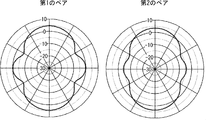
- FIG. 5 is a diagram showing a simulation result of azimuth directivity of the antenna device.
- the antenna pattern of the first pair (or third pair) is shown on the left side of FIG.
- the antenna pattern of the second pair (or the fourth pair) is shown on the right side of FIG.
- each pair has a good omni directivity. Therefore, according to the present embodiment, it is possible to realize the omni directivity with a simple configuration. Therefore, it is possible to increase the degree of freedom in the installation angle and direction.
- the antenna device 100 has four pairs, that is, eight antennas, but the number of antennas is not particularly limited. Specifically, the antenna device 100 may have at least two pairs, for example, the first antenna 1 to the fourth antenna 4. This makes it possible to suppress sneak interference even when transmission and reception are performed at the same time.
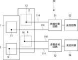
- FIG. 6 is a diagram schematically showing the configuration of the communication circuit 50 mounted on the antenna device 100.
- the communication circuit 50 includes an in-phase distribution circuit 51, an anti-phase synthesis circuit 52, a transmission circuit 53, and a reception circuit 54.
- the in-phase distribution circuit 51 is connected to the first antenna 1 and the second antenna 2 via the power supply line 114.
- the in-phase distribution circuit 51 is connected to the transmission circuit 53.
- the transmission circuit 53 outputs the modulated analog transmission/reception signal to the in-phase distribution circuit 51.
- the in-phase distribution circuit 51 branches the transmission signal from the transmission circuit 53 and supplies it to the first antenna 1 and the second antenna 2 in phase. Specifically, the in-phase distribution circuit 51 distributes the transmission signal 1:1 and supplies the transmission signal to the first antenna 1 and the second antenna 2.
- an analog distributor can be used as the in-phase distribution circuit 51.
- the anti-phase synthesis circuit 52 is connected to the third antenna 3 and the fourth antenna 4 via the power supply line 114.
- the reception signal from the third antenna 3 and the reception signal from the fourth antenna 4 are input to the anti-phase combining circuit 52.
- the anti-phase synthesis circuit 52 synthesizes the two received signals in anti-phase.
- the anti-phase synthesis circuit 52 has an analog delay circuit that gives a delay time corresponding to 180° of the radio frequency.
- the reverse phase synthesis circuit 52 has an analog synthesizer.
- the anti-phase synthesis circuit 52 delays one of the received signals and then synthesizes the two received signals.
- the anti-phase combining circuit 52 outputs the combined reception signal to the receiving circuit 54.
- the receiving circuit 54 demodulates the received signal.
- the analog communication circuit 50 By using the analog communication circuit 50 in this way, it is possible to suppress the sneaking in with a simple configuration. Note that, for the fourth pair, a circuit similar to the antiphase synthesis circuit 52 of the second pair can be used. As for the third pair of combining circuits, an in-phase combining circuit having no delay circuit can be used as in the first pair.
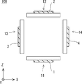
- FIG. 7 is an XZ plan view schematically showing the arrangement of the first antenna 1 to the fourth antenna 4.
- FIG. 8 is a perspective view showing the arrangement of the third antenna 3 and the fourth antenna.
- the configurations of the third antenna 3 and the fourth antenna 4 are different from those in the first embodiment.
- the configurations of the first antenna 1 and the second antenna 2 are the same as those of the first embodiment. Therefore, in FIG. 9, the first antenna 1 and the second antenna 2 are omitted.
- the installation angles of the third antenna 3 and the fourth antenna 4 are rotated 90 degrees in the horizontal direction.
- the third antenna 3 is arranged facing the ⁇ X direction
- the fourth antenna 4 is arranged facing the +X direction.
- the third antenna 3 and the fourth antenna 4 are arranged at intervals in the X direction.
- the first antenna 1 and the second antenna 2 are arranged between the third antenna 3 and the fourth antenna 4 in the X direction.
- the positions of the first antenna 1 to the fourth antenna 4 are the same in the Y direction.
- the first antenna 1 is arranged facing the ⁇ Z direction
- the second antenna 2 is arranged facing the +Z direction.
- the third antenna 3 and the fourth antenna are arranged between the first antenna 1 and the second antenna 2 in the Z direction. Therefore, in the XZ plane view, the first antenna 1 to the fourth antenna are arranged on each side of the square.
- the direction of the third antenna 3 is rotated 90° in the horizontal direction from the direction of the second antenna 2. That is, when the direction in which the second antenna 2 is facing is rotated by 90° around the Y axis, the direction in which the third antenna 3 is facing becomes. Therefore, the orientation of the first pair and the orientation of the second pair differ by 90°.
- the positional relationship between the first antenna 1 to the fourth antenna 4 has rotational symmetry.
- the distance from the third antenna 3 to the first antenna 1 is equal to the distance from the fourth antenna 4 to the second antenna 2.
- the distance from the third antenna 3 to the second antenna 2 is equal to the distance from the fourth antenna 4 to the first antenna 1.
- the distance from the third antenna 3 to the first antenna 1 is equal to the distance from the third antenna 3 to the second antenna 2.
- the feeding point 11 of the first antenna 1 and the feeding point 12 of the second antenna 2 coincide with each other in XY plan view.
- the feeding point 13 of the third antenna 3 and the feeding point 14 of the fourth antenna 4 coincide with each other. That is, the feeding point 13 of the third antenna 3 and the feeding point 14 of the fourth antenna 4 are arranged at positions that are in a mirror image relationship with each other.
- the first antenna 1 and the second antenna 2 are used for V polarization, and the third antenna 3 and the fourth antenna 4 are used for H polarization. Due to the positional relationship between the feeding point 11 and the feeding point 12, the transmission signal of the first antenna 1 and the transmission signal of the second antenna 2 are in phase. The interference component can be canceled by combining the reception signal of the third antenna 3 and the reception signal of the fourth antenna 4 in antiphase. Further, due to the positional relationship between the feeding point 13 and the feeding point 14, the transmission signal of the third antenna 3 and the transmission signal of the fourth antenna 4 have opposite phases. Therefore, the interference component can be canceled by combining the reception signal of the first antenna 1 and the reception signal of the second antenna 2 in phase. With the configuration of this embodiment, the same effect as that of the first embodiment can be obtained.
- the antenna device 100 includes a first antenna 1, a second antenna 2, a third antenna 3, and a fourth antenna 4.
- the first antenna 1 is a first directional antenna that is arranged facing the first direction and that transmits and receives a signal of the first polarization.
- the second antenna 2 is a second directional antenna that is arranged facing a second direction that is the opposite direction to the first direction and that transmits and receives a signal of the first polarized wave.
- the third antenna 3 is arranged facing the third direction which is obtained by rotating the second direction by 90° or 180° in the horizontal direction, and the third antenna 3 transmits/receives the signal of the second polarization orthogonal to the first polarization.
- Directional antenna is arranged facing the third direction which is obtained by rotating the second direction by 90° or 180° in the horizontal direction, and the third antenna 3 transmits/receives the signal of the second polarization orthogonal to the first polarization.
- the fourth antenna is a fourth directional antenna that is arranged facing a fourth direction, which is the opposite direction to the third direction, and that transmits and receives a signal of the second polarized wave.
- the first antenna 1 is provided with a feeding point 11 (first feeding point).
- the second antenna 2 is provided with a feeding point 12 (second feeding point) arranged so as to be in phase with the feeding point 11.
- the third antenna 3 is provided with a feeding point 13 (third feeding point).
- the fourth antenna 4 is provided with a feeding point 14 (fourth feeding point) arranged so as to have a phase opposite to that of the feeding point 13.
- antenna device 1st antenna 2 2nd antenna 3 3rd antenna 4 4th antenna 5 5th antenna 6 6th antenna 7 7th antenna 8 8th antenna 11-18 Feeding point 51 In-phase distribution circuit 52 In-phase combining circuit 53 Transmitter circuit 54 Receiver circuit 111 Dielectric substrate 112 Front surface conductor 113 Back surface conductor 114 Feed line 115 Connector
Landscapes
- Variable-Direction Aerials And Aerial Arrays (AREA)
- Waveguide Aerials (AREA)
Abstract
La présente invention concerne un dispositif d'antenne ayant des caractéristiques omnidirectionnelles et d'excellentes caractéristiques de réception, et un procédé de communication. Ce dispositif d'antenne comprend : une première antenne (1) qui est placée en regard d'une première direction et transmet et reçoit un signal d'une première polarisation ; une deuxième antenne (2) qui est placée en regard d'une deuxième direction opposée à la première direction, et transmet et reçoit un signal de la première polarisation ; une troisième antenne (3) qui est placée en regard d'une troisième direction obtenue par rotation de la deuxième direction de 90° ou 180° dans une direction horizontale, et transmet et reçoit un signal d'une deuxième polarisation perpendiculaire à la première polarisation ; et une quatrième antenne (4) qui est placée en regard d'une quatrième direction opposée à la troisième direction et transmet et reçoit le signal de la deuxième polarisation. La deuxième antenne (2) comprend un point d'alimentation (14) placé de manière à être en phase avec un point d'alimentation (11) de la première antenne (1). La quatrième antenne (4) comprend un point d'alimentation (14) placé de manière à être en phase inverse avec un point d'alimentation (13) de la troisième antenne.
Priority Applications (1)
| Application Number | Priority Date | Filing Date | Title |
|---|---|---|---|
| US17/299,060 US11949165B2 (en) | 2018-12-12 | 2019-12-10 | Antenna device and communication method |
Applications Claiming Priority (2)
| Application Number | Priority Date | Filing Date | Title |
|---|---|---|---|
| JP2018232935A JP7285420B2 (ja) | 2018-12-12 | 2018-12-12 | アンテナ装置、及び通信方法 |
| JP2018-232935 | 2018-12-12 |
Publications (1)
| Publication Number | Publication Date |
|---|---|
| WO2020122070A1 true WO2020122070A1 (fr) | 2020-06-18 |
Family
ID=71077310
Family Applications (1)
| Application Number | Title | Priority Date | Filing Date |
|---|---|---|---|
| PCT/JP2019/048294 Ceased WO2020122070A1 (fr) | 2018-12-12 | 2019-12-10 | Dispositif d'antenne et procédé de communication |
Country Status (3)
| Country | Link |
|---|---|
| US (1) | US11949165B2 (fr) |
| JP (1) | JP7285420B2 (fr) |
| WO (1) | WO2020122070A1 (fr) |
Cited By (1)
| Publication number | Priority date | Publication date | Assignee | Title |
|---|---|---|---|---|
| JP2021061496A (ja) * | 2019-10-04 | 2021-04-15 | 日本電気株式会社 | 通信装置、及び通信方法 |
Families Citing this family (2)
| Publication number | Priority date | Publication date | Assignee | Title |
|---|---|---|---|---|
| KR102297084B1 (ko) * | 2020-07-28 | 2021-09-02 | 크리모 주식회사 | 안테나 모듈 및 안테나 장치 |
| JP7840613B2 (ja) * | 2022-03-28 | 2026-04-06 | 日本無線株式会社 | 円形アレーアンテナ |
Citations (6)
| Publication number | Priority date | Publication date | Assignee | Title |
|---|---|---|---|---|
| JPH05175727A (ja) * | 1991-12-24 | 1993-07-13 | A T R Koudenpa Tsushin Kenkyusho:Kk | 2周波共用平面アンテナ |
| JPH09219618A (ja) * | 1996-02-13 | 1997-08-19 | Toshiba Corp | 円偏波パッチアンテナ及び無線通信システム |
| CA2373645A1 (fr) * | 2001-03-01 | 2002-09-01 | Mark Timothy James Hunter | Antenne reseau |
| WO2010046144A1 (fr) * | 2008-10-23 | 2010-04-29 | Sony Ericsson Mobile Communications Ab | Ensemble d’antennes |
| WO2012004602A1 (fr) * | 2010-07-07 | 2012-01-12 | Gi Provision Limited | Ensemble d'antennes pour un dispositif de communication sans fil |
| JP2015097338A (ja) * | 2013-11-15 | 2015-05-21 | Kddi株式会社 | アンテナ装置およびアンテナ装置の筐体 |
Family Cites Families (5)
| Publication number | Priority date | Publication date | Assignee | Title |
|---|---|---|---|---|
| JPH01151325A (ja) * | 1987-12-08 | 1989-06-14 | Hitachi Ltd | アンテナおよび無線通信システム |
| JP3176217B2 (ja) * | 1993-05-21 | 2001-06-11 | 三菱電機株式会社 | アンテナ装置 |
| US20130106671A1 (en) * | 2011-10-27 | 2013-05-02 | Electronics And Telecommunications Research | Multi-function feed network and antenna in communication system |
| WO2016063748A1 (fr) * | 2014-10-20 | 2016-04-28 | 株式会社村田製作所 | Module de communication sans fil |
| US10567146B1 (en) * | 2016-06-29 | 2020-02-18 | United States Of America As Represented By The Administrator Of The National Aeronautics And Space Administration | Frequency multiplexed radio frequency identification |
-
2018
- 2018-12-12 JP JP2018232935A patent/JP7285420B2/ja active Active
-
2019
- 2019-12-10 US US17/299,060 patent/US11949165B2/en active Active
- 2019-12-10 WO PCT/JP2019/048294 patent/WO2020122070A1/fr not_active Ceased
Patent Citations (6)
| Publication number | Priority date | Publication date | Assignee | Title |
|---|---|---|---|---|
| JPH05175727A (ja) * | 1991-12-24 | 1993-07-13 | A T R Koudenpa Tsushin Kenkyusho:Kk | 2周波共用平面アンテナ |
| JPH09219618A (ja) * | 1996-02-13 | 1997-08-19 | Toshiba Corp | 円偏波パッチアンテナ及び無線通信システム |
| CA2373645A1 (fr) * | 2001-03-01 | 2002-09-01 | Mark Timothy James Hunter | Antenne reseau |
| WO2010046144A1 (fr) * | 2008-10-23 | 2010-04-29 | Sony Ericsson Mobile Communications Ab | Ensemble d’antennes |
| WO2012004602A1 (fr) * | 2010-07-07 | 2012-01-12 | Gi Provision Limited | Ensemble d'antennes pour un dispositif de communication sans fil |
| JP2015097338A (ja) * | 2013-11-15 | 2015-05-21 | Kddi株式会社 | アンテナ装置およびアンテナ装置の筐体 |
Cited By (2)
| Publication number | Priority date | Publication date | Assignee | Title |
|---|---|---|---|---|
| JP2021061496A (ja) * | 2019-10-04 | 2021-04-15 | 日本電気株式会社 | 通信装置、及び通信方法 |
| JP7358892B2 (ja) | 2019-10-04 | 2023-10-11 | 日本電気株式会社 | 通信装置、及び通信方法 |
Also Published As
| Publication number | Publication date |
|---|---|
| JP7285420B2 (ja) | 2023-06-02 |
| US11949165B2 (en) | 2024-04-02 |
| JP2020096284A (ja) | 2020-06-18 |
| US20220069481A1 (en) | 2022-03-03 |
Similar Documents
| Publication | Publication Date | Title |
|---|---|---|
| US12160031B2 (en) | Feed network of base station antenna, base station antenna, and base station | |
| CN101542840B (zh) | 多波束天线 | |
| US8126417B2 (en) | Data processing device with beam steering and/or forming antennas | |
| US10153561B2 (en) | Antenna arrangement | |
| US10008782B2 (en) | Low coupling full-duplex MIMO antenna array with coupled signal cancelling | |
| JP2022533763A (ja) | アンテナユニット及び端末機器 | |
| US6823177B1 (en) | Radio station with circularly polarised antennas | |
| JP7358880B2 (ja) | 偏波共用アレイアンテナ及びその製造方法 | |
| CN110911814A (zh) | 一种天线单元及电子设备 | |
| WO2020122070A1 (fr) | Dispositif d'antenne et procédé de communication | |
| US12113289B2 (en) | Dual-frequency and dual-polarization antenna array and electronic device | |
| KR101412135B1 (ko) | Mimo용 수평 편파 무지향성 안테나 | |
| JP7358892B2 (ja) | 通信装置、及び通信方法 | |
| WO2018047234A1 (fr) | Dispositif d'antenne et système de communication mimo | |
| CN118156817A (zh) | 天线阵列及装置 | |
| CN116190979A (zh) | 电子装置 | |
| CN221727467U (zh) | 一种地面宽带过顶补盲全向天线 | |
| CN120854902B (zh) | 一种天线阵列 | |
| JP2025076292A (ja) | アンテナアレイ | |
| TW202537160A (zh) | 天線陣列 | |
| JPH0897632A (ja) | 無線送受信装置 | |
| CN117239391A (zh) | 天线、天线阵列及通信设备 | |
| CN116154472A (zh) | 双极化天线单元、天线模组及基站 | |
| WO2020133390A1 (fr) | Système d'antenne |
Legal Events
| Date | Code | Title | Description |
|---|---|---|---|
| 121 | Ep: the epo has been informed by wipo that ep was designated in this application |
Ref document number: 19895715 Country of ref document: EP Kind code of ref document: A1 |
|
| NENP | Non-entry into the national phase |
Ref country code: DE |
|
| 122 | Ep: pct application non-entry in european phase |
Ref document number: 19895715 Country of ref document: EP Kind code of ref document: A1 |