WO2020122079A1 - Dispositif de traitement d'image, procédé de traitement d'image, et système de traitement d'image - Google Patents
Dispositif de traitement d'image, procédé de traitement d'image, et système de traitement d'image Download PDFInfo
- Publication number
- WO2020122079A1 WO2020122079A1 PCT/JP2019/048353 JP2019048353W WO2020122079A1 WO 2020122079 A1 WO2020122079 A1 WO 2020122079A1 JP 2019048353 W JP2019048353 W JP 2019048353W WO 2020122079 A1 WO2020122079 A1 WO 2020122079A1
- Authority
- WO
- WIPO (PCT)
- Prior art keywords
- image
- vehicle
- unit
- image processing
- display
- Prior art date
- Legal status (The legal status is an assumption and is not a legal conclusion. Google has not performed a legal analysis and makes no representation as to the accuracy of the status listed.)
- Ceased
Links
Images










Classifications
-
- B—PERFORMING OPERATIONS; TRANSPORTING
- B60—VEHICLES IN GENERAL
- B60R—VEHICLES, VEHICLE FITTINGS, OR VEHICLE PARTS, NOT OTHERWISE PROVIDED FOR
- B60R1/00—Optical viewing arrangements; Real-time viewing arrangements for drivers or passengers using optical image capturing systems, e.g. cameras or video systems specially adapted for use in or on vehicles
- B60R1/006—Side-view mirrors, e.g. V-shaped mirrors located at the front or rear part of the vehicle
- B60R1/007—Side-view mirrors, e.g. V-shaped mirrors located at the front or rear part of the vehicle specially adapted for covering the lateral blind spot not covered by the usual rear-view mirror
-
- H—ELECTRICITY
- H04—ELECTRIC COMMUNICATION TECHNIQUE
- H04N—PICTORIAL COMMUNICATION, e.g. TELEVISION
- H04N7/00—Television systems
- H04N7/18—Closed-circuit television [CCTV] systems, i.e. systems in which the video signal is not broadcast
- H04N7/181—Closed-circuit television [CCTV] systems, i.e. systems in which the video signal is not broadcast for receiving images from a plurality of remote sources
-
- H—ELECTRICITY
- H04—ELECTRIC COMMUNICATION TECHNIQUE
- H04N—PICTORIAL COMMUNICATION, e.g. TELEVISION
- H04N13/00—Stereoscopic video systems; Multi-view video systems; Details thereof
- H04N13/30—Image reproducers
- H04N13/366—Image reproducers using viewer tracking
- H04N13/383—Image reproducers using viewer tracking for tracking with gaze detection, i.e. detecting the lines of sight of the viewer's eyes
-
- B—PERFORMING OPERATIONS; TRANSPORTING
- B60—VEHICLES IN GENERAL
- B60R—VEHICLES, VEHICLE FITTINGS, OR VEHICLE PARTS, NOT OTHERWISE PROVIDED FOR
- B60R1/00—Optical viewing arrangements; Real-time viewing arrangements for drivers or passengers using optical image capturing systems, e.g. cameras or video systems specially adapted for use in or on vehicles
- B60R1/02—Rear-view mirror arrangements
-
- B—PERFORMING OPERATIONS; TRANSPORTING
- B60—VEHICLES IN GENERAL
- B60R—VEHICLES, VEHICLE FITTINGS, OR VEHICLE PARTS, NOT OTHERWISE PROVIDED FOR
- B60R1/00—Optical viewing arrangements; Real-time viewing arrangements for drivers or passengers using optical image capturing systems, e.g. cameras or video systems specially adapted for use in or on vehicles
- B60R1/20—Real-time viewing arrangements for drivers or passengers using optical image capturing systems, e.g. cameras or video systems specially adapted for use in or on vehicles
- B60R1/22—Real-time viewing arrangements for drivers or passengers using optical image capturing systems, e.g. cameras or video systems specially adapted for use in or on vehicles for viewing an area outside the vehicle, e.g. the exterior of the vehicle
- B60R1/23—Real-time viewing arrangements for drivers or passengers using optical image capturing systems, e.g. cameras or video systems specially adapted for use in or on vehicles for viewing an area outside the vehicle, e.g. the exterior of the vehicle with a predetermined field of view
- B60R1/26—Real-time viewing arrangements for drivers or passengers using optical image capturing systems, e.g. cameras or video systems specially adapted for use in or on vehicles for viewing an area outside the vehicle, e.g. the exterior of the vehicle with a predetermined field of view to the rear of the vehicle
-
- B—PERFORMING OPERATIONS; TRANSPORTING
- B60—VEHICLES IN GENERAL
- B60R—VEHICLES, VEHICLE FITTINGS, OR VEHICLE PARTS, NOT OTHERWISE PROVIDED FOR
- B60R1/00—Optical viewing arrangements; Real-time viewing arrangements for drivers or passengers using optical image capturing systems, e.g. cameras or video systems specially adapted for use in or on vehicles
- B60R1/20—Real-time viewing arrangements for drivers or passengers using optical image capturing systems, e.g. cameras or video systems specially adapted for use in or on vehicles
- B60R1/31—Real-time viewing arrangements for drivers or passengers using optical image capturing systems, e.g. cameras or video systems specially adapted for use in or on vehicles providing stereoscopic vision
-
- G—PHYSICS
- G06—COMPUTING OR CALCULATING; COUNTING
- G06T—IMAGE DATA PROCESSING OR GENERATION, IN GENERAL
- G06T11/00—Two-dimensional [2D] image generation
-
- G—PHYSICS
- G08—SIGNALLING
- G08G—TRAFFIC CONTROL SYSTEMS
- G08G1/00—Traffic control systems for road vehicles
- G08G1/16—Anti-collision systems
- G08G1/167—Driving aids for lane monitoring, lane changing, e.g. blind spot detection
-
- H—ELECTRICITY
- H04—ELECTRIC COMMUNICATION TECHNIQUE
- H04N—PICTORIAL COMMUNICATION, e.g. TELEVISION
- H04N13/00—Stereoscopic video systems; Multi-view video systems; Details thereof
- H04N13/30—Image reproducers
- H04N13/361—Reproducing mixed stereoscopic images; Reproducing mixed monoscopic and stereoscopic images, e.g. a stereoscopic image overlay window on a monoscopic image background
-
- H—ELECTRICITY
- H04—ELECTRIC COMMUNICATION TECHNIQUE
- H04N—PICTORIAL COMMUNICATION, e.g. TELEVISION
- H04N13/00—Stereoscopic video systems; Multi-view video systems; Details thereof
- H04N13/30—Image reproducers
- H04N13/363—Image reproducers using image projection screens
-
- H—ELECTRICITY
- H04—ELECTRIC COMMUNICATION TECHNIQUE
- H04N—PICTORIAL COMMUNICATION, e.g. TELEVISION
- H04N23/00—Cameras or camera modules comprising electronic image sensors; Control thereof
- H04N23/60—Control of cameras or camera modules
- H04N23/64—Computer-aided capture of images, e.g. transfer from script file into camera, check of taken image quality, advice or proposal for image composition or decision on when to take image
-
- H—ELECTRICITY
- H04—ELECTRIC COMMUNICATION TECHNIQUE
- H04N—PICTORIAL COMMUNICATION, e.g. TELEVISION
- H04N5/00—Details of television systems
- H04N5/222—Studio circuitry; Studio devices; Studio equipment
- H04N5/262—Studio circuits, e.g. for mixing, switching-over, change of character of image, other special effects ; Cameras specially adapted for the electronic generation of special effects
- H04N5/265—Mixing
-
- H—ELECTRICITY
- H04—ELECTRIC COMMUNICATION TECHNIQUE
- H04N—PICTORIAL COMMUNICATION, e.g. TELEVISION
- H04N7/00—Television systems
- H04N7/18—Closed-circuit television [CCTV] systems, i.e. systems in which the video signal is not broadcast
-
- B—PERFORMING OPERATIONS; TRANSPORTING
- B60—VEHICLES IN GENERAL
- B60R—VEHICLES, VEHICLE FITTINGS, OR VEHICLE PARTS, NOT OTHERWISE PROVIDED FOR
- B60R1/00—Optical viewing arrangements; Real-time viewing arrangements for drivers or passengers using optical image capturing systems, e.g. cameras or video systems specially adapted for use in or on vehicles
- B60R1/12—Mirror assemblies combined with other articles, e.g. clocks
- B60R2001/1253—Mirror assemblies combined with other articles, e.g. clocks with cameras, video cameras or video screens
-
- B—PERFORMING OPERATIONS; TRANSPORTING
- B60—VEHICLES IN GENERAL
- B60R—VEHICLES, VEHICLE FITTINGS, OR VEHICLE PARTS, NOT OTHERWISE PROVIDED FOR
- B60R2300/00—Details of viewing arrangements using cameras and displays, specially adapted for use in a vehicle
- B60R2300/10—Details of viewing arrangements using cameras and displays, specially adapted for use in a vehicle characterised by the type of camera system used
-
- B—PERFORMING OPERATIONS; TRANSPORTING
- B60—VEHICLES IN GENERAL
- B60R—VEHICLES, VEHICLE FITTINGS, OR VEHICLE PARTS, NOT OTHERWISE PROVIDED FOR
- B60R2300/00—Details of viewing arrangements using cameras and displays, specially adapted for use in a vehicle
- B60R2300/10—Details of viewing arrangements using cameras and displays, specially adapted for use in a vehicle characterised by the type of camera system used
- B60R2300/105—Details of viewing arrangements using cameras and displays, specially adapted for use in a vehicle characterised by the type of camera system used using multiple cameras
-
- B—PERFORMING OPERATIONS; TRANSPORTING
- B60—VEHICLES IN GENERAL
- B60R—VEHICLES, VEHICLE FITTINGS, OR VEHICLE PARTS, NOT OTHERWISE PROVIDED FOR
- B60R2300/00—Details of viewing arrangements using cameras and displays, specially adapted for use in a vehicle
- B60R2300/20—Details of viewing arrangements using cameras and displays, specially adapted for use in a vehicle characterised by the type of display used
-
- B—PERFORMING OPERATIONS; TRANSPORTING
- B60—VEHICLES IN GENERAL
- B60R—VEHICLES, VEHICLE FITTINGS, OR VEHICLE PARTS, NOT OTHERWISE PROVIDED FOR
- B60R2300/00—Details of viewing arrangements using cameras and displays, specially adapted for use in a vehicle
- B60R2300/20—Details of viewing arrangements using cameras and displays, specially adapted for use in a vehicle characterised by the type of display used
- B60R2300/202—Details of viewing arrangements using cameras and displays, specially adapted for use in a vehicle characterised by the type of display used displaying a blind spot scene on the vehicle part responsible for the blind spot
-
- B—PERFORMING OPERATIONS; TRANSPORTING
- B60—VEHICLES IN GENERAL
- B60R—VEHICLES, VEHICLE FITTINGS, OR VEHICLE PARTS, NOT OTHERWISE PROVIDED FOR
- B60R2300/00—Details of viewing arrangements using cameras and displays, specially adapted for use in a vehicle
- B60R2300/60—Details of viewing arrangements using cameras and displays, specially adapted for use in a vehicle characterised by monitoring and displaying vehicle exterior scenes from a transformed perspective
- B60R2300/602—Details of viewing arrangements using cameras and displays, specially adapted for use in a vehicle characterised by monitoring and displaying vehicle exterior scenes from a transformed perspective with an adjustable viewpoint
- B60R2300/605—Details of viewing arrangements using cameras and displays, specially adapted for use in a vehicle characterised by monitoring and displaying vehicle exterior scenes from a transformed perspective with an adjustable viewpoint the adjustment being automatic
-
- B—PERFORMING OPERATIONS; TRANSPORTING
- B60—VEHICLES IN GENERAL
- B60R—VEHICLES, VEHICLE FITTINGS, OR VEHICLE PARTS, NOT OTHERWISE PROVIDED FOR
- B60R2300/00—Details of viewing arrangements using cameras and displays, specially adapted for use in a vehicle
- B60R2300/80—Details of viewing arrangements using cameras and displays, specially adapted for use in a vehicle characterised by the intended use of the viewing arrangement
- B60R2300/8046—Details of viewing arrangements using cameras and displays, specially adapted for use in a vehicle characterised by the intended use of the viewing arrangement for replacing a rear-view mirror system
-
- B—PERFORMING OPERATIONS; TRANSPORTING
- B60—VEHICLES IN GENERAL
- B60R—VEHICLES, VEHICLE FITTINGS, OR VEHICLE PARTS, NOT OTHERWISE PROVIDED FOR
- B60R2300/00—Details of viewing arrangements using cameras and displays, specially adapted for use in a vehicle
- B60R2300/80—Details of viewing arrangements using cameras and displays, specially adapted for use in a vehicle characterised by the intended use of the viewing arrangement
- B60R2300/8066—Details of viewing arrangements using cameras and displays, specially adapted for use in a vehicle characterised by the intended use of the viewing arrangement for monitoring rearward traffic
Definitions
- the present technology relates to an image processing device, an image processing method, and an image processing system, and more specifically, to an image processing device suitable for application to an on-vehicle electronic mirror.
- Patent Document 1 in order to solve the fact that the appearance of the electronic mirror differs from the appearance of the actual mirror, the range of the camera image displayed on the display by using the relative position of the driver's head with respect to the display. A technique for changing the variable is proposed.
- a three-dimensional model of an individual subject is generated from a multi-viewpoint image captured by a plurality of cameras, and the three-dimensional model is rearranged in a virtual space.
- Technology is used. In recent years, such technology has begun to be used for TV broadcasting such as watching sports.
- the amount of calculation required for a series of image processing is enormous, and application to a real-time system with a limited amount of calculation such as a vehicle-mounted electronic mirror requires waiting for further improvement in image processing performance.
- the purpose of this technology is to easily realize a sense of distance by motion parallax.
- An image processing apparatus includes a processing unit that obtains a display image by superimposing an image showing the vehicle on a captured image obtained by capturing the rear of the vehicle.
- the processing unit obtains a display image by superimposing an image showing the vehicle on a captured image obtained by photographing the rear of the vehicle.
- the image showing the vehicle may be a computer graphics image.
- the computer graphics image it is possible to increase the degree of freedom in generating the image showing the vehicle.
- the captured image obtained by capturing the rear of the vehicle is the captured image captured by the image capturing device attached to the rear portion of the vehicle, and the image showing the vehicle is the vehicle interior image. May be.
- the display image corresponds to the room mirror display.
- the captured image obtained by capturing the rear of the vehicle includes a captured image captured by a capturing device attached to the side of the vehicle, and the image showing the vehicle is a vehicle body image, May be done.
- the display image corresponds to the side mirror display.
- a display image is obtained by superimposing an image showing the vehicle on a captured image obtained by photographing the rear of the vehicle.
- the display image is not formed only by the captured image obtained by capturing the rear part of the vehicle, but the image showing the vehicle is superimposed on the captured image to obtain the display image. It is easy to provide a sense of distance.
- the processing unit may change the superimposed positional relationship between the captured image and the image showing the vehicle according to the movement of the driver's viewpoint.
- a motion parallax similar to that when actually looking at the rearview mirror is generated, and the driver's perception of the distance can be assisted.
- the processing unit arranges the captured image and the image showing the vehicle in a three-dimensional space, obtains a virtual viewpoint position that changes according to the movement of the driver's viewpoint, and determines the captured image as a captured image based on the visual field determined by the virtual viewpoint position.
- the display image may be obtained by converting the image showing the vehicle into the projective coordinate system.
- the processing unit may arrange the captured image at a position of a predetermined object located behind the vehicle.
- the predetermined object may be the object closest to the vehicle or the object seen by the driver.
- the processing unit may be configured to obtain the virtual viewpoint position that changes according to the movement of the driver's viewpoint, based on the reference viewpoint position and the reference virtual viewpoint position registered for each driver. This makes it possible to obtain an optimum display image for each driver.
- the processing unit may superimpose an image showing a vehicle on a captured image so that the captured image can be seen through.
- the processing unit may superimpose an image showing a vehicle on a captured image so that the captured image can be seen through.
- FIG. 6 is a flowchart showing an example of a normal operation flow in the image processing device. It is a figure which shows the change of the overlapping degree of a drawing object movement by viewpoint movement. It is a figure which shows the variation of drawing processing. It is a figure for demonstrating the prior art regarding a side mirror. It is a figure for explaining an electronic mirror which replaces a side mirror to which this art is applied. It is a figure which shows an example of a component arrangement
- positioning of the element required for drawing in virtual space. FIG. 19 is a block diagram illustrating a configuration example of hardware of a computer.
- FIG. 1 shows an example of the arrangement of components of a vehicle 10 as an embodiment.
- the vehicle 10 has a vehicle body (body) 100, a vehicle body opening (window) 101, and an interior object 102 such as a seat.
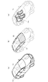
- 2A shows a vehicle body 100
- a hatched portion in FIG. 2B shows a vehicle body opening (window) 101
- FIG. 2C shows an interior object 102 such as a seat.
- the vehicle 10 also has a rear photographing section 103, a rear distance measuring section 104, a viewpoint measuring section 105, and a line-of-sight measuring section 106.
- the rear photographing unit 103 is composed of, for example, a CMOS (Complementary Metal Oxide Semiconductor) camera, and is attached to a rear side outer shell of the vehicle 10 so as to photograph the rear.
- the rear distance measuring unit 104 is composed of, for example, a ToF (Time of Flight) type distance image sensor, and is attached to the rear side outer shell of the vehicle 10 so as to acquire a rear distance image.
- ToF Time of Flight
- the viewpoint measuring unit 105 detects the viewpoint position of the driver (user).
- the viewpoint measuring unit 105 is attached inside the front side of the vehicle 10.
- the viewpoint measuring unit 105 includes, for example, a CMOS camera, and measures the position of the driver's eyes as the viewpoint position based on the image captured by the camera.
- the viewpoint measuring unit 105 may measure the driver's viewpoint position based on an image captured by an infrared camera, for example.
- the line-of-sight measurement unit 106 detects the line of sight of the driver.
- the line-of-sight measurement unit 106 is attached inside the front side of the vehicle 10.
- the line-of-sight measurement unit 106 includes, for example, a CMOS camera, and detects the line of sight of the driver, that is, where the driver is looking, based on the image of the driver's eyes.
- the vehicle 10 also includes a video display unit (display) 107, a user operation unit 108, and an image processing device 109.
- the image display unit 107 is attached inside the front side of the vehicle 10 instead of the conventional rearview mirror, and has a substantially rectangular display surface.
- the image display unit 107 is composed of an LCD (liquid crystal display), an organic EL (Electronic Luminescent) panel, or the like.
- the user operation unit 108 constitutes a user interface that receives various operations by the driver.
- the user operation unit 108 includes, for example, mechanical operation buttons arranged on the in-front panel, and a touch panel arranged on the screen of the image display unit 107.
- the video display unit 107 basically displays a rear image of the vehicle 10, but if it has a touch panel function, a UI (User Interface) display for user operation is also displayed if necessary. ..
- the image processing device 109 performs processing for obtaining a display image to be displayed on the video display unit 107.
- the image processing device 109 is arranged at an arbitrary location inside the vehicle 10, for example, an infront panel portion as illustrated.
- the image processing device 109 obtains a display image by superimposing a vehicle interior image (seat, headrest, window, pillar, etc.) as an image showing the vehicle 10 on the camera image obtained by the rear photographing unit 103 in 3DCG. ..
- a vehicle interior image as an image showing the vehicle 10 on the camera image obtained by the rear photographing unit 103 in 3DCG. ..
- the display image is not formed only by the camera image but the display image is obtained by superimposing the vehicle interior image on the camera image, it is possible to easily realize the sense of distance by the motion parallax. ..
- the image processing device 109 changes the superimposed positional relationship between the captured image and the vehicle interior image in accordance with the driver's viewpoint movement obtained by the viewpoint measuring unit 105.
- the driver can be caused to have a motion parallax that is close to that when he is looking at an actual rearview mirror, and the driver's perception of the distance can be assisted.
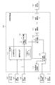
- FIG. 3 shows a configuration example of the image processing apparatus 109.
- the image processing device 109 includes a storage unit 111, a viewing frustum shape position calculation unit 112, an object history storage unit 113, a camera image layout calculation unit 115, a virtual space layout calculation unit 116, and a projection calculation unit 117. It has an image drawing unit 118.
- the image processing device 109 adds a camera image obtained by shooting the rear side to the virtual space in addition to the configuration object of the image processing, that is, the 3D CG data (body, window, interior, etc.) of the vehicle 10. And a view frustum obtained based on the virtual viewpoint position and the virtual image display unit 107A is placed. Then, the image processing apparatus 109 outputs an image generated by this view frustum as a display image to be displayed on the video display unit 107 after performing an enlargement/reduction process as necessary.
- the size of the virtual video display unit 107A is the same as the size of the video display unit 107, the scaling process is unnecessary.
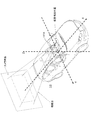
- the image processing apparatus 109 measures the movement of the driver's viewpoint position measured by the viewpoint measuring unit 105 as a relative motion with respect to the reference viewpoint position, and correspondingly the virtual viewpoint position. Is moved from the reference virtual viewpoint position to change the virtual image display unit 107A, and thus the image (image) displayed on the image display unit 107, and provide the driver with appropriate motion parallax.
- the storage unit 111 stores the registered reference viewpoint position and reference visibility setting information for each driver, and further stores 3D CG data of the vehicle.
- the reference field of view is a standard backward field of view, and means a field of view by a view frustum formed by the virtual viewpoint position and the virtual image display unit 107A. Therefore, the information on the reference field of view setting is information on the reference virtual viewpoint position and the position and size of the virtual video display unit 107A. It should be noted that it may be possible to fix all the information on the reference visibility setting. Further, it is possible to fix only the position and size of the virtual video display unit 107A in the information of the reference visibility setting.
- FIG. 6 shows an example of a rear view that is preferable as the reference view.
- the vanishing point is slightly above the center of the screen while traveling on a straight horizontal road.
- the intersection of the broken lines extending in the vertical and horizontal directions represents the center of the screen.
- the image processing apparatus 109 performs an initialization flow at the time of activation such as power-on, identifies a driver (user), and obtains information on the reference viewpoint position and the reference visibility setting corresponding to the driver from the storage unit 111. It is read and used in the subsequent normal operation flow.
- the driver is specified, for example, by an operation from the user operation unit 108. Although detailed description is omitted, it is conceivable that the driver is automatically specified by a conventionally known authentication method such as face authentication, fingerprint authentication, or voice authentication.
- the flowchart in Fig. 7 shows an example of the initialization flow.
- the image processing apparatus 109 starts the process in step ST1.
- the image processing apparatus 109 specifies a user, that is, a driver in step ST2.
- the image processing apparatus 109 reads out the information about the reference visual field setting of the identified driver from the storage unit 111.
- the image processing apparatus 109 reads out the information on the specified reference viewpoint position of the driver from the storage unit 111.
- the image processing apparatus 109 ends the series of processes in the initialization flow in step ST5.
- the flowchart of FIG. 8 shows an example of the registration flow of the reference viewpoint position.
- the image processing apparatus 109 starts processing in step ST11.
- the image processing device 109 acquires the driver's current viewpoint position based on the detection result of the viewpoint measuring unit 105, and also calculates the driver's current viewpoint position based on the detection result of the line-of-sight measuring unit 106. Get the line-of-sight position.
- step ST13 the image processing apparatus 109 determines whether or not the viewpoint is within the viewpoint detection area (see FIG. 9). When the viewpoint is not within the viewpoint detection area, the image processing apparatus 109 returns to the process of step ST12. On the other hand, when the viewpoint is within the viewpoint detection region, the image processing apparatus 109 determines in step ST14 whether the line of sight is on the video display unit 107 within the line of sight detection region (see FIG. 9). When the line of sight is not on the image display unit 107, the image processing apparatus 109 returns to the process of step ST12. On the other hand, when the line of sight is on the video display unit 107, the image processing apparatus 109 moves to the processing in step ST15.
- step ST15 the image processing apparatus 109 determines whether or not the line of sight is on the video display unit 107 for a certain time or more, here for one second or more. When the line of sight is not on the video display unit 107 for 1 second or more, the image processing apparatus 109 returns to the process of step ST12. On the other hand, when the line of sight is continuously present on the video display unit 107 for one second or more, the image processing apparatus 109 associates with the driver the current viewpoint position as the reference viewpoint position in the storage unit 111 in step ST16. sign up. After that, the image processing apparatus 109 ends the series of processes in step ST17.
- the driver can perform the operation by operating the user operation unit 108, for example, on a touch panel arranged on the screen of the video display unit 107.
- the visibility setting (virtual viewpoint position, etc.) is adjusted so that the appearance of the rear view at the reference viewpoint position is desired, and the adjusted visibility setting is associated with the driver as the reference view setting. And is registered in the storage unit 111.
- the view frustum shape position calculation unit 112 calculates a virtual position based on the reference viewpoint position and reference view setting information read from the storage unit 111 and the current viewpoint position detected by the viewpoint measurement unit 105. Calculate the shape and position of the view frustum in space.
- the virtual viewpoint position (current virtual viewpoint position) displaced from the reference virtual viewpoint position according to the deviation (distance or direction deviation) of the viewpoint position (current viewpoint position) from the reference viewpoint position is obtained ( 5), the position and shape of the view frustum with the virtual viewpoint as the apex is obtained based on the virtual viewpoint position and the size and position of the virtual image display unit 107A (see FIG. 4).
- the camera image arrangement calculation unit 115 is a rear range image acquired by the rear distance measurement unit 104, a rear camera image acquired by the rear photographing unit 103, and a view frustum obtained by the view frustum shape arrangement calculation unit 112.
- the arrangement distance of the camera image in the virtual space is calculated based on the shape and position of the.
- the appearance (motion parallax) of the subject in the camera image that appears and disappears in the vehicle interior image (body, window, interior) varies.
- an image actually taken by the camera is a three-dimensional space compressed in the distance direction, and objects (objects) A to D at different distances are converted into two-dimensional images in the distance. It was shot in a size that fits. Therefore, this camera image is not perfectly appropriate wherever it is placed in the three-dimensional space, and is only an appropriate position for an object existing at a distance where the camera image is placed. Note that in reality, an image that is out of the depth of field of the camera lens is blurred, but here it is considered as an ideal pan-focus camera.
- FIG. 11 shows a case where a camera image is placed at the distance of the object A (image arrangement A) and a case where a camera image is placed at the distance of the object D (image arrangement D).
- 12(a), (b), and (c) show the visual fields when the visual field (corresponding to the view frustum determined by the virtual visual point position) is moved to the right, center, and left.
- the range of the camera image entering the field of view differs between the case of the image arrangement A and the case of the image arrangement D, and the inside of the camera image changes as the view moves. You can see that the moving range is different. This is the motion parallax with respect to the object in the camera image, and by placing the camera image at the distance of the object (object) of interest, the motion parallax occurring between the object and the vehicle can be correctly expressed.
- the feature of this technology is that by giving up motion parallax other than the object of interest, the motion parallax for the object of interest is provided with a relatively small amount of calculation.
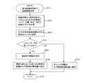
- FIG. 13 illustrates an example of the processing flow of the camera image layout calculation unit 115. This processing example takes into consideration the events (1), (2), and (3) described above, and can be realized using only the distance image acquired by the rear distance measuring unit 104.
- the camera image layout calculation unit 115 executes the processing flow shown in the flowchart of FIG. 13 every time the distance measurement unit 104 acquires a distance image.
- the backward distance measuring unit 104 acquires the distance image at a frequency of 120 fps, for example.
- step ST21 the camera image layout calculation unit 115 starts processing at the timing when the rear distance measurement unit 104 acquires a distance image.
- step ST22 the camera image placement calculation unit 115 extracts an object (object) from the distance image and creates a list of positions, shapes, sizes, and distances of objects having a certain size or more.
- step ST23 the camera image arrangement calculation unit 115 stores the created list in the object history storage unit 113.
- step ST24 the camera image placement calculation unit 115 browses the history data of the object history storage unit 113, searches for the same object from the feature of the shape, deletes the object without history from the list, and deletes the history. For some objects, the relative speed with the vehicle is calculated and added to the list.
- step ST25 the camera image layout calculation unit 115 excludes objects out of the effective shooting distance of the camera from the created list. This is intended to remove objects at distances where the camera is out of focus. If the camera image cannot be captured even if the distance can be measured, it is excluded as the camera image arrangement distance is inappropriate.
- step ST26 the camera image layout calculation unit 115 deletes from the list the object moving away at a certain speed or more.
- the camera image placement calculation unit 115 deletes from the list the objects that deviate from the view frustum and its vicinity.
- step ST28 the camera image layout calculation unit 115 determines whether or not data remains in the list.
- the camera image placement calculation unit 115 adopts the distance from the vehicle to the closest object as the camera image placement distance in step ST29. After the process of step ST29, the camera image arrangement calculation unit 115 ends the series of processes in step ST30.
- a predetermined default distance is adopted as the camera image arrangement distance in step ST31.
- the default distance is a distance suitable for placing a distant view. In presenting a sense of distance, it is desirable to be far away as long as the computing ability allows.
- the default distance is determined with reference to the calculation capability of the backward distance measuring unit 104.
- the default distance may be about 100 m for Lidar (light detection and ranging) and about 250 m for the ToF sensor.
- the flowchart of FIG. 14 shows another example of the processing flow of the camera image layout calculation unit 115.
- This processing example takes into consideration the events (1), (3), and (4) described above, and is obtained by the rear photographing unit 103 in addition to the distance image acquired by the rear distance measuring unit 104. It can be realized by using a camera image.
- the camera image placement calculation unit 115 executes the processing flow shown in the flowchart of FIG. 14 every time the rear distance measurement unit 104 acquires a distance image.
- the backward distance measuring unit 104 acquires the distance image at a frequency of 120 fps, for example.
- the camera image layout calculation unit 115 starts the process at the timing when the rear distance measurement unit 104 acquires the distance image in step ST61.
- the camera image placement calculation unit 115 extracts objects from the distance image and creates a list of positions, shapes, sizes, and distances of objects having a certain size or more.
- step ST63 the camera image layout calculation unit 115 excludes objects that deviate from the effective shooting distance of the camera from the created list. This is intended to remove objects at distances where the camera is out of focus. If the camera image cannot be captured even if the distance can be measured, it is excluded as the camera image arrangement distance is inappropriate.
- step ST64 the camera image layout calculation unit 115 recognizes an object by image recognition and deletes an object (for example, a bird, dead leaf, etc.) that is not suitable for the image layout from the list.
- step ST65 the camera image placement calculation unit 115 deletes from the list the objects that deviate from the view frustum and its vicinity.
- step ST66 the camera image layout calculation unit 115 determines whether or not data remains in the list.
- the camera image placement calculation unit 115 adopts the distance from the vehicle to the closest object as the camera image placement distance in step ST67. After the process of step ST67, the camera image placement calculation unit 115 ends the series of processes in step ST68.
- step ST69 a predetermined default distance (distance suitable for distant view placement) is adopted as the camera image placement distance in step ST69.
- the camera image arrangement calculation unit 115 ends the series of processes in step ST68.
- the flowchart of FIG. 15 shows still another example of the processing flow of the camera image layout calculation unit 115.
- This processing example considers the above-mentioned events (1), (3), and (5), and in addition to the distance image acquired by the rearward distance measuring unit 104, the driver ( This can be realized by using the line-of-sight detection result of the (user).
- the camera image placement calculation unit 115 executes the processing flow shown in the flowchart of FIG. 15 every time the rear distance measurement unit 104 acquires a distance image.
- the backward distance measuring unit 104 acquires the distance image at a frequency of 120 fps, for example.
- the camera image layout calculation unit 115 starts the process at the timing when the distance measurement unit 104 acquires the distance image in step ST71.
- the camera image placement calculation unit 115 extracts objects from the distance image and creates a list of positions, shapes, sizes, and distances for objects having a certain size or more.
- step ST73 the camera image layout calculation unit 115 excludes objects out of the effective shooting distance of the camera from the created list. Then, in step ST74, the camera image layout calculation unit 115 determines whether or not data remains in the list.
- the camera image layout calculation unit 115 acquires the line of sight of the driver (user) obtained by the line-of-sight measurement unit 106 in step ST75. Then, in step ST76, the camera image placement calculation unit 115 adopts the distance of the object closest to the line of sight as the camera image placement distance. After the process of step ST76, the camera image arrangement calculation unit 115 ends the series of processes in step ST77.
- step ST78 a predetermined default distance (distance suitable for arranging a distant view) is adopted as the camera image arrangement distance in step ST78.
- the camera image arrangement calculation unit 115 ends the series of processes in step ST77.
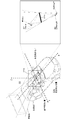
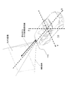
- FIG. 16 shows the arrangement position of the camera image in the virtual space.
- the camera image is obtained by being photographed by the rear photographing unit 103 at a predetermined photographing angle of view.
- This camera image is arranged in the virtual space at a position separated from the rear portion of the vehicle 10 by the camera image arrangement distance calculated by the camera image arrangement calculation unit 115.
- the virtual space arrangement calculation unit 116 arranges elements necessary for drawing in the virtual space. That is, the virtual space arrangement calculation unit 116 arranges the 3D CG data (body, window, interior, etc.) of the vehicle 10 stored in the storage unit 111 in the virtual space, and calculates it by the camera image arrangement calculation unit 115.
- the camera image is arranged at the position of the determined camera image arrangement distance, and further, the view frustum is arranged based on the shape and position calculated by the view frustum shape arrangement calculation unit 112.
- FIG. 17 shows an arrangement example of elements required for drawing in the virtual space.
- the projection calculation unit 117 uses the virtual video display unit 107A as a projection plane to convert an object in the virtual space into a projected image.
- the image drawing unit 118 draws details of the camera image and 3D CG data on the projection image obtained by the projection calculation unit 117, and further enlarges or reduces the image size to match the size of the video display unit 107. Then, the display image supplied to the video display unit 107 is output.
- FIG. 18 shows an example of a display image obtained by the image drawing unit 118.
- the flowchart in FIG. 19 shows an example of a normal operation flow in the image processing apparatus 109.
- the image processing apparatus 109 starts the process in step ST41.
- step ST42 the image processing apparatus 109 acquires the current viewpoint position based on the detection result of the viewpoint measuring unit 105.
- step ST43 the image processing apparatus 109 calculates the virtual viewpoint position by converting the difference between the reference viewpoint position and the current viewpoint position into the difference of the virtual viewpoint from the reference virtual viewpoint position (see FIG. 5). ..
- step ST44 the image processing apparatus 109 calculates the shape and position of the view frustum from the virtual viewpoint position.
- step ST45 the image processing apparatus 109 acquires the rear camera image obtained by the rear photographing unit 103.
- the image processing device 109 calculates the camera image arrangement distance in step ST46.
- step ST47 the image processing apparatus 109 arranges the 3D CG data (body, window, interior, etc.) of the vehicle 10, camera images, and view frustums, which are elements necessary for drawing, in the virtual space. (See Figure 17).
- step ST48 the image processing apparatus 109 converts the constituents in the virtual space into a projective coordinate system to obtain a projected image.
- step ST49 the image processing apparatus 109 performs a process of drawing details of the camera image and 3DCG data on the projected image to obtain a display image.
- the image processing device 109 outputs the display image to the video display unit 107 in step ST50.
- the image processing apparatus 109 returns to the processing of step ST42 and repeats the same processing as described above.
- the image processing apparatus 109 continuously performs the above-described processing of the normal operation flow in synchronization with the update frequency of the video display unit 107, for example, 120 fps.
- the degree of overlap of the drawing target objects is appropriately changed depending on the movement of the viewpoint and the distance to the rear object of interest, that is, an appropriate motion parallax is obtained.
- the driver (user) can obtain an appropriate sense of distance with respect to the rear camera image.
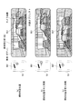
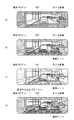
- 20A, 20B, and 20C show examples of display images displayed on the video display unit 107.
- 20A shows a case where the driver's viewpoint position is at the standard viewpoint position
- FIG. 20B shows a case where the driver's viewpoint position moves to the right from the standard viewpoint position
- 20(c) shows a case where the driver's viewpoint position moves to the left from the standard viewpoint position. It can be seen that the degree of overlap between the vehicle interior CG image and the object (vehicle) in the camera image changes depending on the viewpoint position of the driver.
- interior objects and car bodies create blind spots where the rear cannot be seen if they are real mirrors, but with the present technology, it is possible to draw them transparently when drawing, or to hide some of them. It is also possible to maintain a wide rear view while assisting the perception of a sense of distance by motion parallax.
- FIG. 21A the rear seat as an interior object is hidden.
- FIG. 21(b) shows a vehicle body and a rear seat as an interior object having a low transmittance
- FIG. 21(c) shows a vehicle body and a rear seat as an interior object having a high transmittance. is there.
- the interior object or the vehicle body may be drawn with a transmittance of 0%, and an image like a real mirror may be generated and displayed.
- the interior object is not limited to a sheet or the like, and it is possible to further emphasize the distance perception by drawing a pattern on the window glass, for example.
- horizontal lines are provided as objects on the window glass.
- the image processing apparatus 109 shown in FIG. 3 superimposes the vehicle interior image on the camera image obtained by photographing the rear of the vehicle 10 to form a conventional interior mirror.
- the display image to be displayed on the video display unit 107 arranged in place of is obtained.
- the display image is not formed only by the camera image obtained by photographing the rear of the vehicle 10, but the display image is obtained by superimposing the vehicle interior image on the camera image. Can be easily realized.
- the image processing device 109 shown in FIG. 3 changes the superposition positional relationship between the camera image and the vehicle interior image according to the movement of the driver's viewpoint. Therefore, a motion parallax similar to that when actually looking at the rearview mirror is generated, and the driver's perception of the distance can be assisted.
- the image processing device 109 shown in FIG. 3 arranges the camera image and the image showing the vehicle in a three-dimensional space, and obtains the virtual viewpoint position that changes according to the movement of the driver's viewpoint.
- the display image is obtained by converting the camera image and the vehicle interior image into the projective coordinate system according to the field of view determined by the virtual viewpoint position. Therefore, it is possible to accurately change the superposition positional relationship between the camera image and the vehicle interior image according to the movement of the driver's viewpoint.
- the image processing apparatus 109 shown in FIG. 3 arranges the camera image at the position of a target object (object) existing behind the vehicle 10 to obtain a display image. Is. Therefore, the object of interest can be arranged at the correct position in the three-dimensional space with the correct size, and the motion parallax that occurs between the object and the vehicle interior image can be accurately expressed.
- Electronic mirrors for vehicles have the advantage that they are not affected by the loading of luggage, and can provide a rear view with less blind spots than actual mirrors.
- the electronic mirror has a problem that it is difficult to intuitively perceive a sense of distance. Binocular parallax, vergence angle, accommodation, and motion parallax are important factors for humans to perceive distance.
- the motion parallax is a phenomenon in which two or more objects having different distances appear and disappear with the movement of the viewpoint, and the display position of the camera image is moved as in the technique described in Patent Document 1 described above. It is thought that the effect of presenting a sense of distance by motion parallax is very weak because of little change in visual hiding.
- objects in the vehicle interior are superimposed and drawn on the rear camera image, and motion parallax is added to them to actively provide a sense of distance due to motion parallax, which is intuitive and familiar to the driver (user).
- a simple electronic mirror can be provided.
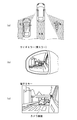
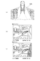
- FIG. 22A shows an example of a blind spot range when a conventional side mirror or an electronic mirror that replaces the conventional side mirror is used.
- FIG. 22B shows an example of an image displayed on a conventional side mirror. In this case, it is possible to obtain a sense of distance of the rear object due to the difference in size of the rear object and the motion parallax with the reflected vehicle body.
- FIG. 22C shows an example of a display image of an electronic mirror that replaces the conventional side mirror. In this case, since the motion parallax does not occur even if the viewpoint moves, it is difficult to obtain a sense of distance unlike the real mirror.
- FIG. 23( a) shows an example of a blind spot range when an electronic mirror that replaces the side mirror to which the present technology is applied is used.
- the driver can also visually recognize the rear of the vehicle, which is a blind spot with the conventional side mirror or an electronic mirror that replaces the conventional side mirror.
- 23B and 23C show examples of display images of an electronic mirror that substitutes for the side mirror to which the present technology is applied.
- the own vehicle body is overlaid and drawn in 3DCG, it is possible to provide a sense of distance due to motion parallax. Further, as shown in FIG. 23(c), by transparently overlapping the own vehicle body, the back of the own vehicle can be visually recognized.
- FIG. 24 shows an example of the arrangement of components of the vehicle 10. 24, parts corresponding to those in FIG. 1 are designated by the same reference numerals, and detailed description thereof will be appropriately omitted.
- the vehicle 10 has a vehicle body 100, a vehicle body opening (window) 101, and an interior object 102 such as a seat.
- the vehicle 10 also includes a rear photographing section 103, a rear distance measuring section 104, a viewpoint measuring section 105, and a line-of-sight measuring section 106.
- the vehicle 10 also has a right rear photographing section 103R, a right rear distance measuring section 104R, a left rear photographing section 103L, and a left rear distance measuring section 104L.
- Each of the right rear photographing unit 103R and the left rear photographing unit 103L is composed of, for example, a CMOS camera, and is attached to the side mirror position of the vehicle 10, for example, so as to photograph the rear.
- the right rear distance measuring unit 104R and the left rear distance measuring unit 104L are each configured of, for example, a ToF type distance image sensor, and are configured to acquire a rear distance image at a conventional side mirror position of the vehicle 10, for example. It is installed.
- the vehicle 10 also includes a right rear image display unit (display) 107R, a left rear image display unit (display) 107L, a user operation unit 108, and an image processing device 109S.
- the right rear image display unit 107R and the left rear image display unit 107L are each configured by an LCD, an organic EL panel, or the like, are attached to the right and left positions inside the front side of the vehicle 10, and have a substantially rectangular display. Has a face.
- the user operation unit 108 constitutes a user interface that receives various operations by the driver.
- the user operation unit 108 includes, for example, mechanical operation buttons arranged on the infront panel, a touch panel arranged on the screens of the right rear image display unit 107R and the left rear image display unit 107L, and the like. There is.
- the image processing device 109S performs a process for obtaining a display image to be displayed on the right rear video display unit 107R and the left rear video display unit 107L.
- the image processing device 109S is arranged at an arbitrary location inside the vehicle 10, for example, an infront panel portion as illustrated.
- the image processing apparatus 109S superimposes a body image as an image showing the vehicle 10 on a camera image obtained by the rear photographing unit 103, the right rear photographing unit 103R, and the left rear photographing unit 103L by 3D CG. To obtain a display image.
- the display image is not composed only of the camera image, but the body image is superimposed on the camera image to obtain the display image, so that it is possible to easily provide a sense of distance due to motion parallax. Further, by transparently superimposing the vehicle body image, the driver (user) can visually recognize an invisible object hidden behind the vehicle.
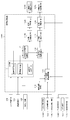
- FIG. 25 shows a configuration example of the image processing device 109S.
- the image processing device 109S includes a storage unit 111, a view frustum shape position calculation unit 112, an object history storage unit 113, a camera image layout calculation unit 115, a virtual space layout calculation unit 116, and a projection calculation unit (right).
- the image processing device 109S arranges a camera image obtained by photographing the rear side in the virtual space in addition to the component to be image-processed, that is, the 3D CG data (body etc.) of the vehicle 10. Then, the image processing apparatus 109S obtains a view frustum based on the virtual viewpoint position related to the right rear display and the virtual image display unit, and performs an enlargement/reduction process on the image generated by the view frustum as necessary. After the application, the image is output as a right rear display image displayed on the right rear image display unit 107R.
- the image processing apparatus 109S obtains a view frustum based on the virtual viewpoint position related to the left rear display and the virtual image display unit, and enlarges or reduces the image generated by this view frustum as necessary. After the processing of (1) is performed, the image is output as a left rear display image displayed on the left rear image display unit 107L.
- the image processing apparatus 109S measures the movement of the driver's viewpoint position measured by the viewpoint measuring unit 105 as a relative motion with respect to the reference viewpoint position, and moves the virtual viewpoint position from the reference virtual viewpoint position correspondingly.
- the images (images) displayed on the right rear image display unit 107R and the left rear image display unit 107L are changed, and the driver is provided with an appropriate motion parallax.
- the storage unit 111 stores the registered reference viewpoint position for each driver, information on the reference visibility setting related to the right rear display and the left rear display, and further 3D CG data of the vehicle.
- the view frustum shape position calculation unit 112 based on the information on the reference viewpoint position and the reference field of view setting read from the storage unit 111, and the current viewpoint position detected by the viewpoint measurement unit 105, on the right side in the virtual space. The shapes and positions of the two viewing frustums for the rear display and the left rear display are calculated.
- the camera image arrangement calculation unit 115 includes a rear distance image acquired by the right rear distance measuring unit 104R, the rear distance measuring unit 104, and the left rear distance measuring unit 104L, the right rear photographing unit 103R, the rear photographing unit 103, and the left rear photographing.
- the shapes and positions of the two viewing frustums for the right rear display and the left rear display which are obtained by the viewing frustum shape placement calculating unit 112, and the like.
- the arrangement distance of the camera image of is calculated.
- the distance to the object is calculated as the placement distance so that an appropriate motion parallax can be provided for the object of interest.
- the object of interest is different for the right rear display and the left rear display. In that case, the arrangement distances of the camera images for the right rear display and the left rear display are calculated to have different values.
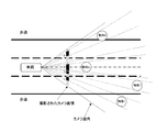
- FIG. 26 shows the arrangement positions of camera images in the virtual space.
- the camera image is obtained by being photographed by the right rear photographing unit 103R, the rear photographing unit 103, and the left rear photographing unit 103L at a predetermined photographing angle of view.
- This camera image is arranged in the virtual space at a position separated from the rear portion of the vehicle 10 by the camera image arrangement distance calculated by the camera image arrangement calculation unit 115.
- the virtual space placement calculation unit 116 places elements required for drawing in the virtual space. That is, the virtual space layout calculation unit 116 arranges the 3DCG data (body etc.) of the vehicle 10 stored in the storage unit 111 in the virtual space, and the camera image layout calculation unit 115 calculates the camera image.
- the camera image is arranged at the position of the arrangement distance, and further, two view frustums for the right rear display and the left rear display are arranged based on the shape and position calculated by the view frustum shape arrangement calculation unit 112. ..
- FIG. 27 shows an arrangement example of elements required for drawing in the virtual space.
- the projection calculation unit (right) 117R converts the object in the virtual space into a projection image using the right virtual image display unit 107A as the projection surface.
- the image drawing unit (right) 118R draws the details of the camera image and 3DCG data on the projection image obtained by the projection calculation unit 117R, and further sets the size of the image to the size of the right rear video display unit 107R. Enlargement/reduction processing for matching is performed, and the display image to be supplied to the right rear video display unit 107R is output.
- the projection calculation unit (left) 117L converts the object in the virtual space into a projection image by using the left virtual video display unit 107A as a projection surface.
- the image drawing unit (left) 118L draws the details of the camera image and 3DCG data on the projection image obtained by the projection calculation unit 117L, and further sets the size of the image to the size of the left rear video display unit 107L. Enlargement/reduction processing for matching is performed, and the display image to be supplied to the left rear video display unit 107L is output.
- the basic processing flow in the image processing apparatus 109S is the same as the processing flow in the image processing apparatus 109 in the above-described embodiment, except that the processing is performed separately for the left and right display units, and therefore the description thereof will be given here. Is omitted.
- the series of processes in the above-described image processing devices 109 and 109S can be executed by hardware or software.
- a program forming the software is installed in the computer.
- the computer includes a computer incorporated in dedicated hardware and, for example, a general-purpose personal computer capable of executing various functions by installing various programs.
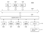
- FIG. 28 is a block diagram showing a hardware configuration example of the computer 400 that executes the series of processes described above by a program.
- a CPU Central Processing Unit
- ROM Read Only Memory
- RAM Random Access Memory
- An input/output interface 405 is further connected to the bus 404.
- An input unit 406, an output unit 407, a recording unit 408, a communication unit 409, and a drive 410 are connected to the input/output interface 405.
- the input unit 406 includes an input switch, a button, a microphone, an image sensor, and the like.
- the output unit 407 includes a display, a speaker and the like.
- the recording unit 408 includes a hard disk, a non-volatile memory, or the like.
- the communication unit 409 includes a network interface or the like.
- the drive 410 drives a removable medium 411 such as a magnetic disk, an optical disk, a magneto-optical disk, or a semiconductor memory.
- the CPU 401 loads the program recorded in the recording unit 408 into the RAM 403 via the input/output interface 405 and the bus 404 and executes the program, for example. A series of processing is performed.
- the program executed by the computer 400 can be provided, for example, by recording it on a removable medium 411 such as a package medium. Further, the program can be provided via a wired or wireless transmission medium such as a local area network, the Internet, or digital satellite broadcasting.
- the program can be installed in the recording unit 408 via the input/output interface 405 by mounting the removable medium 411 in the drive 410. Further, the program can be received by the communication unit 409 via a wired or wireless transmission medium and installed in the recording unit 408. In addition, the program can be installed in the ROM 402 or the recording unit 408 in advance.
- the program executed by the computer may be a program in which processing is performed in time series in the order described in this specification, or in parallel or at a necessary timing such as when a call is made. It may be a program for processing.
- An image processing apparatus including a processing unit that obtains a display image by superimposing an image showing the vehicle on a captured image obtained by capturing the rear of the vehicle.
- the image processing apparatus according to (1) wherein the image showing the vehicle is a computer graphics image.
- the photographed image obtained by photographing the rear of the vehicle is a photographed image photographed by a photographing device attached to the rear portion of the vehicle, The image showing the vehicle is a vehicle interior image.
- the photographed image obtained by photographing the rear of the vehicle includes the photographed image photographed by the photographing device attached to the side portion of the vehicle, The image showing the vehicle is a vehicle body image.
- the image processing device according to (1) or (2) is a vehicle body image.
- the image processing device changes the superimposed positional relationship between the captured image and the image showing the vehicle in accordance with the movement of the driver's viewpoint.
- the processing unit is Arrange the photographed image and the image showing the vehicle in a three-dimensional space, A virtual viewpoint position that changes according to the movement of the driver's viewpoint is obtained, and the display image is obtained by converting the captured image and the image showing the vehicle into a projective coordinate system according to the field of view determined by the virtual viewpoint position.
- the image processing device according to.
- the image processing device (8) The image processing device according to (7), wherein the predetermined object is an object closest to the vehicle. (9) The image processing device according to (7), wherein the predetermined object is an object viewed by the driver. (10) The processing unit obtains a virtual viewpoint position that changes according to the movement of the driver's viewpoint, based on the reference viewpoint position and the reference virtual viewpoint position registered for each driver. The image processing device according to any one of 1) to 4). (11) The image processing device according to any one of (1) to (10), wherein the processing unit superimposes an image showing the vehicle on the captured image so that the captured image can be seen through. (12) An image processing method including a procedure for obtaining a display image by superimposing an image showing the vehicle on a captured image obtained by capturing the rear of the vehicle.
- a photographing device for photographing the rear of the vehicle A processing unit that obtains a display image by superimposing an image showing the vehicle on a captured image captured by the capturing device, An image processing system comprising a display device for displaying the display image obtained by the processing unit.
- Computer A program that causes a captured image obtained by photographing the rear of a vehicle to be superimposed on an image representing the vehicle to obtain a display image.
Landscapes
- Engineering & Computer Science (AREA)
- Multimedia (AREA)
- Mechanical Engineering (AREA)
- Signal Processing (AREA)
- Physics & Mathematics (AREA)
- General Physics & Mathematics (AREA)
- Theoretical Computer Science (AREA)
- Closed-Circuit Television Systems (AREA)
- Image Processing (AREA)
- Image Analysis (AREA)
- Traffic Control Systems (AREA)
Abstract
Priority Applications (8)
| Application Number | Priority Date | Filing Date | Title |
|---|---|---|---|
| CN201980080325.6A CN113170081B (zh) | 2018-12-11 | 2019-12-10 | 图像处理装置、图像处理方法和图像处理系统 |
| JP2020559260A JP7494735B2 (ja) | 2018-12-11 | 2019-12-10 | 画像処理装置、画像処理方法および画像処理システム |
| US17/299,794 US11603043B2 (en) | 2018-12-11 | 2019-12-10 | Image processing apparatus, image processing method, and image processing system |
| EP19896603.8A EP3896961B1 (fr) | 2018-12-11 | 2019-12-10 | Dispositif de traitement d'image, procédé de traitement d'image, et système de traitement d'image |
| KR1020217016314A KR20210100609A (ko) | 2018-12-11 | 2019-12-10 | 화상 처리 장치, 화상 처리 방법 및 화상 처리 시스템 |
| EP24183995.0A EP4420930A3 (fr) | 2018-12-11 | 2019-12-10 | Dispositif de traitement d'image, procédé de traitement d'image et système de traitement d'image |
| US18/167,909 US11813988B2 (en) | 2018-12-11 | 2023-02-13 | Image processing apparatus, image processing method, and image processing system |
| US18/477,675 US12296749B2 (en) | 2018-12-11 | 2023-09-29 | Image processing apparatus, image processing method, and image processing system |
Applications Claiming Priority (2)
| Application Number | Priority Date | Filing Date | Title |
|---|---|---|---|
| JP2018-232045 | 2018-12-11 | ||
| JP2018232045 | 2018-12-11 |
Related Child Applications (2)
| Application Number | Title | Priority Date | Filing Date |
|---|---|---|---|
| US17/299,794 A-371-Of-International US11603043B2 (en) | 2018-12-11 | 2019-12-10 | Image processing apparatus, image processing method, and image processing system |
| US18/167,909 Continuation US11813988B2 (en) | 2018-12-11 | 2023-02-13 | Image processing apparatus, image processing method, and image processing system |
Publications (1)
| Publication Number | Publication Date |
|---|---|
| WO2020122079A1 true WO2020122079A1 (fr) | 2020-06-18 |
Family
ID=71077295
Family Applications (1)
| Application Number | Title | Priority Date | Filing Date |
|---|---|---|---|
| PCT/JP2019/048353 Ceased WO2020122079A1 (fr) | 2018-12-11 | 2019-12-10 | Dispositif de traitement d'image, procédé de traitement d'image, et système de traitement d'image |
Country Status (6)
| Country | Link |
|---|---|
| US (3) | US11603043B2 (fr) |
| EP (2) | EP3896961B1 (fr) |
| JP (1) | JP7494735B2 (fr) |
| KR (1) | KR20210100609A (fr) |
| CN (1) | CN113170081B (fr) |
| WO (1) | WO2020122079A1 (fr) |
Cited By (1)
| Publication number | Priority date | Publication date | Assignee | Title |
|---|---|---|---|---|
| EP4122767A1 (fr) * | 2021-07-22 | 2023-01-25 | Continental Automotive Systems, Inc. | Simulation d'image de miroir de véhicule |
Families Citing this family (6)
| Publication number | Priority date | Publication date | Assignee | Title |
|---|---|---|---|---|
| KR102913858B1 (ko) | 2018-12-11 | 2026-01-19 | 소니그룹주식회사 | 화상 처리 장치, 화상 처리 방법 및 화상 처리 시스템 |
| EP4310280A4 (fr) * | 2021-04-20 | 2024-05-29 | NEC Corporation | Dispositif de traitement d'informations, système de commande de véhicule, procédé de traitement d'informations et support non transitoire lisible par ordinateur |
| WO2022256255A1 (fr) * | 2021-06-01 | 2022-12-08 | Stoneridge, Inc. | Affichage de système de surveillance de caméra comprenant une manipulation de parallaxe |
| JP7733964B2 (ja) * | 2022-04-13 | 2025-09-04 | パナソニックオートモーティブシステムズ株式会社 | 表示制御装置 |
| US12361688B2 (en) * | 2022-09-28 | 2025-07-15 | Toyota Research Institute, Inc. | System and method for building multi-view machine learning datasets from fleet data |
| CN116442909A (zh) * | 2023-04-06 | 2023-07-18 | 深圳市豪恩汽车电子装备股份有限公司 | 车载后视系统及标定方法 |
Citations (5)
| Publication number | Priority date | Publication date | Assignee | Title |
|---|---|---|---|---|
| JP2004287845A (ja) * | 2003-03-20 | 2004-10-14 | Aisin Seiki Co Ltd | 車両運転者の視線検出装置 |
| JP2012226665A (ja) * | 2011-04-21 | 2012-11-15 | Canon Inc | 情報処理装置、その処理方法、プログラム及び撮像装置 |
| JP2013216286A (ja) | 2012-04-12 | 2013-10-24 | Suzuki Motor Corp | 車両周囲確認用モニター装置 |
| JP2017111739A (ja) * | 2015-12-18 | 2017-06-22 | 株式会社デンソー | 運転支援装置、運転支援方法 |
| JP2017196911A (ja) * | 2016-04-25 | 2017-11-02 | 本田技研工業株式会社 | 画像表示装置 |
Family Cites Families (22)
| Publication number | Priority date | Publication date | Assignee | Title |
|---|---|---|---|---|
| JP2002135765A (ja) * | 1998-07-31 | 2002-05-10 | Matsushita Electric Ind Co Ltd | カメラキャリブレーション指示装置及びカメラキャリブレーション装置 |
| JP2005269010A (ja) * | 2004-03-17 | 2005-09-29 | Olympus Corp | 画像生成装置、画像生成プログラム、及び画像生成方法 |
| JP2006119843A (ja) * | 2004-10-20 | 2006-05-11 | Olympus Corp | 画像生成方法およびその装置 |
| US8179435B2 (en) * | 2005-09-28 | 2012-05-15 | Nissan Motor Co., Ltd. | Vehicle surroundings image providing system and method |
| JP5088669B2 (ja) * | 2007-03-23 | 2012-12-05 | 株式会社デンソー | 車両周辺監視装置 |
| EP1974998B1 (fr) * | 2007-03-26 | 2011-05-25 | Aisin AW Co., Ltd. | Procédé d'assistance à la conduite et appareil d'assistance à la conduite |
| JP5115136B2 (ja) * | 2007-10-16 | 2013-01-09 | 株式会社デンソー | 車両後方監視装置 |
| JP5177217B2 (ja) * | 2008-02-26 | 2013-04-03 | 富士通株式会社 | 画像処理装置、画像処理方法、画像処理プログラム及び車載端末 |
| JP4914458B2 (ja) * | 2009-02-12 | 2012-04-11 | 株式会社日本自動車部品総合研究所 | 車両周辺表示装置 |
| JP5630518B2 (ja) | 2012-03-14 | 2014-11-26 | 株式会社デンソー | 運転支援装置 |
| US20140114534A1 (en) * | 2012-10-19 | 2014-04-24 | GM Global Technology Operations LLC | Dynamic rearview mirror display features |
| TWI531495B (zh) * | 2012-12-11 | 2016-05-01 | Automatic Calibration Method and System for Vehicle Display System | |
| WO2014130049A1 (fr) * | 2013-02-25 | 2014-08-28 | Johnson Controls Technology Company | Systèmes et procédés d'affichage augmenté pour rétroviseurs |
| JP6364702B2 (ja) | 2013-03-29 | 2018-08-01 | アイシン精機株式会社 | 画像表示制御装置、画像表示システム、および表示ユニット |
| JP6446925B2 (ja) * | 2014-09-05 | 2019-01-09 | アイシン精機株式会社 | 画像表示制御装置および画像表示システム |
| US10503989B2 (en) * | 2015-09-28 | 2019-12-10 | Kyocera Corporation | Image processing apparatus, imaging apparatus, camera monitor system, and image processing method |
| JP6493361B2 (ja) * | 2016-04-01 | 2019-04-03 | 株式会社デンソー | 車両用装置、車両用プログラム、フィルタ設計プログラム |
| EP3487172A4 (fr) * | 2016-07-13 | 2019-07-10 | Sony Corporation | Dispositif de génération d'images, procédé de génération d'images, et programme |
| JP2018110328A (ja) * | 2017-01-04 | 2018-07-12 | 株式会社デンソーテン | 画像処理装置および画像処理方法 |
| JP6649914B2 (ja) * | 2017-04-20 | 2020-02-19 | 株式会社Subaru | 画像表示装置 |
| JP6965563B2 (ja) * | 2017-05-11 | 2021-11-10 | 株式会社アイシン | 周辺監視装置 |
| CN110520692B (zh) * | 2017-05-24 | 2024-03-26 | 古野电气株式会社 | 影像生成装置 |
-
2019
- 2019-12-10 WO PCT/JP2019/048353 patent/WO2020122079A1/fr not_active Ceased
- 2019-12-10 JP JP2020559260A patent/JP7494735B2/ja active Active
- 2019-12-10 KR KR1020217016314A patent/KR20210100609A/ko not_active Ceased
- 2019-12-10 EP EP19896603.8A patent/EP3896961B1/fr active Active
- 2019-12-10 CN CN201980080325.6A patent/CN113170081B/zh active Active
- 2019-12-10 US US17/299,794 patent/US11603043B2/en active Active
- 2019-12-10 EP EP24183995.0A patent/EP4420930A3/fr active Pending
-
2023
- 2023-02-13 US US18/167,909 patent/US11813988B2/en active Active
- 2023-09-29 US US18/477,675 patent/US12296749B2/en active Active
Patent Citations (5)
| Publication number | Priority date | Publication date | Assignee | Title |
|---|---|---|---|---|
| JP2004287845A (ja) * | 2003-03-20 | 2004-10-14 | Aisin Seiki Co Ltd | 車両運転者の視線検出装置 |
| JP2012226665A (ja) * | 2011-04-21 | 2012-11-15 | Canon Inc | 情報処理装置、その処理方法、プログラム及び撮像装置 |
| JP2013216286A (ja) | 2012-04-12 | 2013-10-24 | Suzuki Motor Corp | 車両周囲確認用モニター装置 |
| JP2017111739A (ja) * | 2015-12-18 | 2017-06-22 | 株式会社デンソー | 運転支援装置、運転支援方法 |
| JP2017196911A (ja) * | 2016-04-25 | 2017-11-02 | 本田技研工業株式会社 | 画像表示装置 |
Cited By (1)
| Publication number | Priority date | Publication date | Assignee | Title |
|---|---|---|---|---|
| EP4122767A1 (fr) * | 2021-07-22 | 2023-01-25 | Continental Automotive Systems, Inc. | Simulation d'image de miroir de véhicule |
Also Published As
| Publication number | Publication date |
|---|---|
| EP3896961B1 (fr) | 2024-06-26 |
| US12296749B2 (en) | 2025-05-13 |
| EP3896961A1 (fr) | 2021-10-20 |
| US20220041107A1 (en) | 2022-02-10 |
| CN113170081A (zh) | 2021-07-23 |
| US11603043B2 (en) | 2023-03-14 |
| JPWO2020122079A1 (ja) | 2021-10-21 |
| CN113170081B (zh) | 2024-09-24 |
| US11813988B2 (en) | 2023-11-14 |
| EP4420930A2 (fr) | 2024-08-28 |
| JP7494735B2 (ja) | 2024-06-04 |
| US20230191994A1 (en) | 2023-06-22 |
| EP4420930A3 (fr) | 2024-10-09 |
| US20240017669A1 (en) | 2024-01-18 |
| KR20210100609A (ko) | 2021-08-17 |
| EP3896961A4 (fr) | 2022-01-19 |
Similar Documents
| Publication | Publication Date | Title |
|---|---|---|
| EP3896961B1 (fr) | Dispositif de traitement d'image, procédé de traitement d'image, et système de traitement d'image | |
| KR102913050B1 (ko) | 화상 처리 장치, 화상 처리 방법 및 화상 처리 시스템 | |
| JP7428139B2 (ja) | 画像処理装置、画像処理方法および画像処理システム | |
| WO2020122085A1 (fr) | Dispositif de traitement d'image, procédé de traitement d'image, et système de traitement d'image | |
| JP2013205526A (ja) | 表示装置および表示制御方法 |
Legal Events
| Date | Code | Title | Description |
|---|---|---|---|
| 121 | Ep: the epo has been informed by wipo that ep was designated in this application |
Ref document number: 19896603 Country of ref document: EP Kind code of ref document: A1 |
|
| ENP | Entry into the national phase |
Ref document number: 2020559260 Country of ref document: JP Kind code of ref document: A |
|
| NENP | Non-entry into the national phase |
Ref country code: DE |
|
| ENP | Entry into the national phase |
Ref document number: 2019896603 Country of ref document: EP Effective date: 20210712 |
|
| WWR | Wipo information: refused in national office |
Ref document number: 1020217016314 Country of ref document: KR |