WO2020122240A1 - 空気入りタイヤ - Google Patents
空気入りタイヤ Download PDFInfo
- Publication number
- WO2020122240A1 WO2020122240A1 PCT/JP2019/049003 JP2019049003W WO2020122240A1 WO 2020122240 A1 WO2020122240 A1 WO 2020122240A1 JP 2019049003 W JP2019049003 W JP 2019049003W WO 2020122240 A1 WO2020122240 A1 WO 2020122240A1
- Authority
- WO
- WIPO (PCT)
- Prior art keywords
- tire
- pneumatic tire
- rim
- circumferential main
- width
- Prior art date
- Legal status (The legal status is an assumption and is not a legal conclusion. Google has not performed a legal analysis and makes no representation as to the accuracy of the status listed.)
- Ceased
Links
Images




Classifications
-
- B—PERFORMING OPERATIONS; TRANSPORTING
- B60—VEHICLES IN GENERAL
- B60C—VEHICLE TYRES; TYRE INFLATION; TYRE CHANGING; CONNECTING VALVES TO INFLATABLE ELASTIC BODIES IN GENERAL; DEVICES OR ARRANGEMENTS RELATED TO TYRES
- B60C9/00—Reinforcements or ply arrangement of pneumatic tyres
- B60C9/18—Structure or arrangement of belts or breakers, crown-reinforcing or cushioning layers
- B60C9/20—Structure or arrangement of belts or breakers, crown-reinforcing or cushioning layers built-up from rubberised plies each having all cords arranged substantially parallel
- B60C9/22—Structure or arrangement of belts or breakers, crown-reinforcing or cushioning layers built-up from rubberised plies each having all cords arranged substantially parallel the plies being arranged with all cords disposed along the circumference of the tyre
- B60C9/2204—Structure or arrangement of belts or breakers, crown-reinforcing or cushioning layers built-up from rubberised plies each having all cords arranged substantially parallel the plies being arranged with all cords disposed along the circumference of the tyre obtained by circumferentially narrow strip winding
-
- B—PERFORMING OPERATIONS; TRANSPORTING
- B60—VEHICLES IN GENERAL
- B60C—VEHICLE TYRES; TYRE INFLATION; TYRE CHANGING; CONNECTING VALVES TO INFLATABLE ELASTIC BODIES IN GENERAL; DEVICES OR ARRANGEMENTS RELATED TO TYRES
- B60C3/00—Tyres characterised by the transverse section
- B60C3/04—Tyres characterised by the transverse section characterised by the relative dimensions of the section, e.g. low profile
-
- B—PERFORMING OPERATIONS; TRANSPORTING
- B60—VEHICLES IN GENERAL
- B60C—VEHICLE TYRES; TYRE INFLATION; TYRE CHANGING; CONNECTING VALVES TO INFLATABLE ELASTIC BODIES IN GENERAL; DEVICES OR ARRANGEMENTS RELATED TO TYRES
- B60C11/00—Tyre tread bands; Tread patterns; Anti-skid inserts
- B60C11/03—Tread patterns
-
- B—PERFORMING OPERATIONS; TRANSPORTING
- B60—VEHICLES IN GENERAL
- B60C—VEHICLE TYRES; TYRE INFLATION; TYRE CHANGING; CONNECTING VALVES TO INFLATABLE ELASTIC BODIES IN GENERAL; DEVICES OR ARRANGEMENTS RELATED TO TYRES
- B60C11/00—Tyre tread bands; Tread patterns; Anti-skid inserts
- B60C11/03—Tread patterns
- B60C11/04—Tread patterns in which the raised area of the pattern consists only of continuous circumferential ribs, e.g. zig-zag
-
- B—PERFORMING OPERATIONS; TRANSPORTING
- B60—VEHICLES IN GENERAL
- B60C—VEHICLE TYRES; TYRE INFLATION; TYRE CHANGING; CONNECTING VALVES TO INFLATABLE ELASTIC BODIES IN GENERAL; DEVICES OR ARRANGEMENTS RELATED TO TYRES
- B60C9/00—Reinforcements or ply arrangement of pneumatic tyres
- B60C9/18—Structure or arrangement of belts or breakers, crown-reinforcing or cushioning layers
- B60C9/20—Structure or arrangement of belts or breakers, crown-reinforcing or cushioning layers built-up from rubberised plies each having all cords arranged substantially parallel
- B60C9/2003—Structure or arrangement of belts or breakers, crown-reinforcing or cushioning layers built-up from rubberised plies each having all cords arranged substantially parallel characterised by the materials of the belt cords
- B60C9/2009—Structure or arrangement of belts or breakers, crown-reinforcing or cushioning layers built-up from rubberised plies each having all cords arranged substantially parallel characterised by the materials of the belt cords comprising plies of different materials
-
- B—PERFORMING OPERATIONS; TRANSPORTING
- B60—VEHICLES IN GENERAL
- B60C—VEHICLE TYRES; TYRE INFLATION; TYRE CHANGING; CONNECTING VALVES TO INFLATABLE ELASTIC BODIES IN GENERAL; DEVICES OR ARRANGEMENTS RELATED TO TYRES
- B60C9/00—Reinforcements or ply arrangement of pneumatic tyres
- B60C9/18—Structure or arrangement of belts or breakers, crown-reinforcing or cushioning layers
- B60C9/26—Folded plies
- B60C9/263—Folded plies further characterised by an endless zigzag configuration in at least one belt ply, i.e. no cut edge being present
- B60C2009/266—Folded plies further characterised by an endless zigzag configuration in at least one belt ply, i.e. no cut edge being present combined with non folded cut-belt plies
-
- B—PERFORMING OPERATIONS; TRANSPORTING
- B60—VEHICLES IN GENERAL
- B60C—VEHICLE TYRES; TYRE INFLATION; TYRE CHANGING; CONNECTING VALVES TO INFLATABLE ELASTIC BODIES IN GENERAL; DEVICES OR ARRANGEMENTS RELATED TO TYRES
- B60C11/00—Tyre tread bands; Tread patterns; Anti-skid inserts
- B60C11/0008—Tyre tread bands; Tread patterns; Anti-skid inserts characterised by the tread rubber
- B60C2011/0016—Physical properties or dimensions
- B60C2011/0033—Thickness of the tread
Definitions
- the present invention relates to a small-diameter pneumatic tire with improved load bearing capacity.
- the small diameter pneumatic tire as described above has a problem that the contact pressure tends to be uneven because the contact length is short and the contact area is small against the load that must be supported. Such non-uniformity of the ground pressure may cause uneven wear.
- a new small shuttle bus has been proposed that focuses on the transportation of people and goods in the city.
- Such a small shuttle bus has a total length of about 5 m and a total width of about 2 m, and it is assumed that the total vehicle weight may exceed 3 tons. Space saving is also required for pneumatic tires mounted on such small shuttle buses.
- the present invention has been made in view of such a situation, and an object thereof is to provide a pneumatic tire capable of effectively suppressing uneven wear while achieving high load-carrying capacity and space saving. To do.
- One aspect of the present invention includes a tread (tread 20) that is in contact with a road surface, and a belt layer (belt layer 50) provided inside the tread in the tire radial direction, and is a pneumatic tire mounted on a vehicle (vehicle 1).
- the outer diameter of the pneumatic tire is 350mm or more, 600mm or less
- rim width of the rim wheel (rim wheel 100) assembled to the pneumatic tire is RW
- the pneumatic When the tire width of the tire is SW, the relationship of 0.78 ⁇ RW/SW ⁇ 0.99 is satisfied
- the tread has at least two circumferential main grooves (circumferential main grooves 21, 22) extending in the tire circumferential direction.
- the circumferential main groove is formed closer to the tire equator line (tire equator line CL) than the tire width direction outer end of the belt layer.
- FIG. 1 is an overall schematic side view of a vehicle 1 to which a pneumatic tire 10 is attached.
- FIG. 2 is a cross-sectional view of the pneumatic tire 10 and the rim wheel 100.
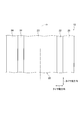
- FIG. 3 is a unit cross-sectional view of the pneumatic tire 10.
- FIG. 4 is a partially developed plan view of the tread 20.
- FIG. 5 is a diagram showing positioning of a typical tire size based on a combination of a tire shape (tire outer diameter OD and tire width SW) and a rim wheel shape (rim diameter RD and rim width RW).
- FIG. 6 is a sectional view of a pneumatic tire 10A according to a modification.
- FIG. 7 is a cross-sectional view of a pneumatic tire 10B according to another modification.
- FIG. 1 is an overall schematic side view of a vehicle 1 equipped with a pneumatic tire 10 according to the present embodiment.
- the vehicle 1 is a four-wheeled vehicle.
- the vehicle 1 is not limited to four wheels, and may have a six-wheel configuration, an eight-wheel configuration, or the like.
- the vehicle 1 is equipped with a predetermined number of pneumatic tires 10 according to the wheel configuration. Specifically, the vehicle 1 is equipped with the pneumatic tire 10 assembled to the rim wheel 100 at a predetermined position.
- the new small shuttle bus belongs to a new small shuttle bus that focuses on transporting people and things in the city.
- the new small shuttle bus is assumed to be a vehicle having a total length of 4 m to 7 m, a total width of about 2 m, and a total vehicle weight of about 3 t.
- the size and the total weight of the vehicle are not necessarily limited to the range, and may be out of the range as long as they are small.
- the small shuttle bus may be used not only for transportation of people but also for transportation of goods, mobile shops, mobile offices, and the like.
- the small shuttle bus is focused on transporting people and goods in the city, so a relatively low traveling speed range (maximum speed of 70 km/h or less, average speed of about 50 km/h) is assumed. .. Therefore, the hydroplaning countermeasure does not have to be emphasized.
- the vehicle 1 is an electric vehicle having an automatic driving function (assuming level 4 or higher), but the automatic driving function is not essential and may not be an electric vehicle. Absent.
- the vehicle 1 is an electric vehicle, it is preferable to use an in-wheel motor (not shown) as a power unit.
- the in-wheel motor the entire unit may be provided in the inner space of the rim wheel 100, or a part of the unit may be provided in the inner space of the rim wheel 100.
- the vehicle 1 When using an in-wheel motor, it is preferable that the vehicle 1 has an independent steering function that allows each wheel to be independently steered. As a result, turning on the spot and lateral movement are possible, and the power transmission mechanism is not required, so that the space efficiency of the vehicle 1 can be improved.
- the pneumatic tire 10 preferably has a diameter as small as possible.
- the pneumatic tire 10 has a load bearing capacity corresponding to the total weight of the vehicle 1 while reducing the tire outer diameter OD (not shown in FIG. 1, see FIG. 2) in order to satisfy such requirements.
- the flatness of the pneumatic tire 10 is low from the viewpoint of improving responsiveness.
- the rim diameter RD of 10 (not shown in FIG. 1, see FIG. 2) is preferably large.
- FIG. 2 is a sectional view of the pneumatic tire 10 and the rim wheel 100. Specifically, FIG. 2 is a cross-sectional view along the tire width direction and tire radial direction of the pneumatic tire 10 assembled to the rim wheel 100. In FIG. 2, cross-section hatching display is omitted (the same applies to FIG. 3 and subsequent figures).
- the Pneumatic tire 10 has a relatively small diameter but is wide.
- the rim diameter RD which is the diameter of the rim wheel 100, is preferably 12 inches or more and 17.5 inches or less.
- the rim diameter RD may be 10 inches or more and 22 inches or less as long as it satisfies the other numerical range.
- the rim diameter RD is the outer diameter of the rim body of the rim wheel 100, and does not include the rim flange 110.
- the tire width SW of the pneumatic tire 10 is preferably 125 mm or more and 255 mm or less. As shown in FIG. 2, the tire width SW means the sectional width of the pneumatic tire 10, and when the pneumatic tire 10 includes a rim guard (not shown), the rim guard portion is not included.
- the flatness of the pneumatic tire 10 is preferably 35% or more and 75% or less.
- the flatness ratio is calculated using Equation 1.
- the tire outer diameter OD which is the outer diameter of the pneumatic tire 10, is 350 mm or more and 600 mm or less.
- the tire outer diameter OD is preferably 500 mm or less.
- the pneumatic tire 10 has the following formulas (2) and (3). Meet a relationship.
- the pneumatic tire 10 preferably satisfies 0.78 ⁇ RW/SW ⁇ 0.98, and more preferably 0.78 ⁇ RW/SW ⁇ 0.95. Further, the pneumatic tire 10 preferably satisfies 0.56 ⁇ RD/OD ⁇ 0.72, and more preferably 0.56 ⁇ RD/OD ⁇ 0.71.
- the pneumatic tire 10 satisfying such a relationship can have an air volume necessary for supporting the total vehicle weight of the vehicle 1 while having a small diameter.
- the air volume needs to be 20,000 cm 3 or more in consideration of load bearing performance. Also, in consideration of space saving, it is necessary to be 80,000 cm 3 or less.
- the rim width RW is not particularly limited as long as the above relationship is satisfied, but it is preferable that the rim width RW is as wide as possible from the viewpoint of securing an air volume.
- the rim width can be 3.8-7.8J.
- the ratio of the rim diameter RD to the tire outer diameter OD is small, that is, the flatness ratio is high.
- the flatness ratio is low from the viewpoint of responsiveness, and in consideration of the accommodation space such as the in-wheel motor, it is preferable that the rim diameter RD is large. Has a trade-off relationship between the air volume and the responsiveness and the accommodation space such as the in-wheel motor.
- the compatible rim width is about 7.5J.
- 215/45R12 is another example of a suitable size. In this case, the compatible rim width is about 7.0J.
- the set internal pressure (normal internal pressure) of the pneumatic tire 10 is assumed to be 400 to 1,100 kPa, and realistically 500 to 900 kPa.
- the regular internal pressure is, for example, the air pressure corresponding to the maximum load capacity of the JATMA (Japan Automobile Tire Manufacturer's Association) YearBook in Japan, and ETRTO in Europe, TRA in the US, and tire standards of other countries correspond to it.
- FIG. 3 is a sectional view of the pneumatic tire 10 alone. Specifically, FIG. 3 is a cross-sectional view of the pneumatic tire 10 taken along the tire width direction and the tire radial direction.
- the pneumatic tire 10 includes a tread 20, a tire side portion 30, a carcass 40, a belt layer 50 and a bead portion 60.
- Tread 20 is the part that contacts the road surface.
- the tread 20 is formed with a pattern (see FIG. 4) according to the usage environment of the pneumatic tire 10 and the type of vehicle to which the pneumatic tire 10 is attached.
- the tread 20 is formed with two circumferential main grooves extending in the tire circumferential direction.
- the tread 20 may have more circumferential grooves formed therein, and may have widthwise grooves extending in the tire width direction formed therein.
- the circumferential groove and the widthwise groove may form a block in contact with the road surface.
- the shape of the block in the tread surface view is not particularly limited.
- the tread 20 is formed with a circumferential main groove 21 and a circumferential main groove 22.
- the circumferential main groove 21 and the circumferential main groove 22 are formed closer to the tire equator line CL than the tire width direction outer end 50e of the belt layer 50.
- the distance between the tire width direction inner end of the circumferential main groove 21 and the tire width direction outer end of the circumferential main groove 22 is W
- the thickness (rubber gauge) of the tread 20 at the position of the tire equator line CL is H. In this case, it is preferable that 1.5 ⁇ W/H ⁇ 6.0 is satisfied, and it is more preferable that 2.0 ⁇ W/H ⁇ 4.0 is satisfied.
- the tire side part 30 is connected to the tread 20 and is located inside the tread 20 in the tire radial direction.
- the tire side portion 30 is an area from the tire width direction outer end of the tread 20 to the upper end of the bead portion 60.
- the tire side portion 30 is sometimes called a sidewall or the like.
- the carcass 40 forms the skeleton of the pneumatic tire 10.
- the carcass 40 has a radial structure in which carcass cords (not shown) radially arranged along the tire radial direction are covered with a rubber material.
- the structure is not limited to the radial structure, and may be a bias structure in which the carcass cords are arranged so as to intersect in the tire radial direction.
- the belt layer 50 is provided inside the tire in the tire radial direction of the tread 20.
- the belt layer 50 has a three-belt structure, but may have a four-belt structure.
- the belt layer 50 includes a pair of intersecting belts in which cords intersect each other.
- the structure of such a belt layer 50 is substantially the same as the structure of the belt layer of a general truck/bus tire.
- the bead portion 60 is connected to the tire side portion 30 and is located inside the tire side portion 30 in the tire radial direction.
- the bead portion 60 has an annular shape extending in the tire circumferential direction, and the carcass 40 is folded back from the tire width direction inner side to the tire width direction outer side via the bead portion 60.
- the bead portion 60 may be provided with a bead filler on the outer side in the tire radial direction of the bead core. Fur may be provided.
- FIG. 4 is a partially developed plan view of the tread 20. As shown in FIG. 4, a plurality of blocks are formed on the tread 20 by the circumferential main groove 21 and the circumferential main groove 22.
- the tread 20 is formed with a central block 23, a shoulder block 24, and a shoulder block 25.
- the central block 23 is formed in a region including the tire equator line CL.
- a circumferential main groove 21 and a circumferential main groove 22 are formed at the ends of the central block 23 in the tire width direction.
- a shoulder block 24 is formed outside the circumferential main groove 21 in the tire width direction.
- a shoulder block 25 is formed outside the circumferential main groove 22 in the tire width direction.
- the circumferential main groove 21 and the circumferential main groove 22 are 25% or more and 95% or less, when the width from the tire equator line CL to the tire width direction outer end 50e of the belt layer 50 is 100%. Is formed in the range of.
- the circumferential main groove 21 and the circumferential main groove 22 are preferably formed in the range of 35% or more and 85% or less, and more preferably in the range of 40% or more and 70% or less.
- the concrete shapes of the circumferential main groove 21 and the circumferential main groove 22 may be straight grooves, zigzag grooves, or curved grooves as long as they extend in the tire circumferential direction.
- the negative rate of the tread 20 is 5% or more and 25% or less. Is preferred.
- the negative rate of the tread 20 is more preferably 7% or more and 20% or less, further preferably 9% or more and 15% or less.
- a sipe in the central block 23 defined by the circumferential main groove 21 and the circumferential main groove 22.
- the distance between the sipes in the tire circumferential direction is preferably 1.5 times or more and 5.0 times or less, and more preferably 2.0 times or more and 4.0 times or less the sipes depth.
- the number of circumferential main grooves be 2 or more and 4 or less.
- the groove width of the circumferential main groove is preferably 2 mm or more and 20 mm or less, and more preferably 3 mm or more and 15 mm or less.
- FIG. 5 is a diagram showing a typical tire size positioning based on a combination of a tire shape (tire outer diameter OD and tire width SW) and a rim wheel shape (rim diameter RD and rim width RW).
- the horizontal axis of the graph shown in FIG. 5 represents the ratio (RW/SW) of the rim width RW and the tire width SW, and the vertical axis represents the ratio of the rim diameter RD and the tire outer diameter OD (RD /OD).
- typical tire size positions are plotted according to the values of RW/SW and RD/OD.
- the area of truck/bus tires is low in both RW/SW and RD/OD.
- the area of tires for passenger cars or light trucks is higher in both RW/SW and RD/OD than tires for trucks and buses.
- the area A1 is included in the area A1.
- the area A1 is in the range of 0.78 ⁇ RW/SW ⁇ 0.99 and 0.56 ⁇ RD/OD ⁇ 0.75.
- Such an area A1 is positioned as an area of a new small-sized shuttle bus tire that focuses on transportation of people and goods in a city like the vehicle 1 described above.
- RD/OD in the area of new small shuttle bus tires does not differ much from RD/OD in the area of passenger car or light truck tires, and some overlap.
- RW/SW in the area of new small shuttle bus tires is higher than RW/SW in the area of passenger car or light truck tires.
- the tire outer diameter OD of the pneumatic tire 10 is 350 mm or more and 600 mm or less. Therefore, the diameter is sufficiently smaller than the size of the vehicle 1, which can contribute to space saving of the vehicle 1.
- the rim width RW with respect to the tire width SW is wide, that is, a wide tire can be configured and is high. It is easy to secure the air volume necessary to exert the load bearing capacity. Note that if the rim width RW becomes too wide, the tire width SW also widens, space efficiency decreases, and the bead portion 60 easily comes off the rim wheel 100.
- the relationship of 0.56 ⁇ RD/OD ⁇ 0.75 is satisfied, so that the rim diameter RD is large with respect to the tire outer diameter OD, and the accommodation space for the in-wheel motor etc. is secured. Easy to do.
- the rim diameter RD becomes too small, the diameter size of the disc brake or the drum brake becomes small. For this reason, the effective contact area of the brake becomes small, and it becomes difficult to secure the required braking performance.
- the rim diameter RD of the pneumatic tire 10 is preferably 12 inches or more and 17.5 inches or less. This makes it possible to secure a necessary and sufficient air volume and a storage space for the in-wheel motor while maintaining the small diameter. In addition, braking performance and driving performance can be ensured.
- the tire width SW of the pneumatic tire 10 is preferably 125 mm or more and 255 mm or less. Further, the flatness of the pneumatic tire 10 is preferably 35% or more and 75% or less. As a result, a necessary and sufficient air volume and a storage space for the in-wheel motor and the like can be secured.
- the circumferential main groove 21 and the circumferential main groove 22 extending in the tire circumferential direction are formed, and the circumferential main groove 21 and the circumferential main groove 22 are tires of the belt layer 50. It is formed closer to the tire equator line CL than the widthwise outer end 50e.
- the circumferential main groove 21 and the circumferential main groove 22 are formed in a region where the ground pressure is particularly high in the small-diameter and wide pneumatic tire 10. Therefore, in the region where the ground contact pressure is high, it is possible to secure the “escape area” for the rubber forming the tread 20. As a result, uneven wear in the region can be effectively suppressed.
- the circumferential main groove 21 and the circumferential main groove 22 are 25% or more and 95% or less, when the width from the tire equator line CL to the tire width direction outer end 50e of the belt layer 50 is 100%. Is formed in the range of. Therefore, the circumferential main groove 21 and the circumferential main groove 22 are formed in the region where the ground pressure is particularly high. As a result, uneven wear in the region can be suppressed more effectively.
- FIG. 6 is a sectional view of a pneumatic tire 10A according to a modification.
- the pneumatic tire 10A includes a belt layer 50A.
- the belt layer 50A includes a core belt 51 and a sheath vest 52.
- the core belt 51 is a belt in which a cord (not shown) inclined at a low angle with respect to the tire width direction is covered with rubber.
- the sheath vest 52 is a tape-shaped belt including a cord, and is wrapped around the entire circumference of the core belt 51.
- Belt layer 50A provides the same function as the interlaced belt layer.
- sheath vest 52 The specific configuration of the sheath vest 52 is described in, for example, Japanese Patent Laid-Open No. 2016-215943.
- the folded end 41 of the carcass 40 folded at the bead portion 60 is provided so as to be wound along the bead core 61.
- the folded-back end portion 41 is in contact with the tire radial outer end of the bead core 61.
- the bead portion 60 may be provided with a bead filler.
- FIG. 7 is a sectional view of a pneumatic tire 10B according to another modification.
- the pneumatic tire 10B includes a belt layer 50B.
- the belt layer 50B is a spiral belt formed by winding a resin-coated cord covered with a resin material in the tire circumferential direction.
- the pneumatic tire 10A and the pneumatic tire 10B also have circumferential main grooves 21 and circumferential main grooves 22 similar to those of the pneumatic tire 10.
- the configuration of the belt layer and the shape of the folded end 41 of the carcass 40 may be appropriately changed according to the characteristics of the vehicle 1.
- the pneumatic tire 10 is assumed to satisfy the relationship of 0.56 ⁇ RD/OD ⁇ 0.75, but the relationship does not necessarily have to be satisfied.
Landscapes
- Engineering & Computer Science (AREA)
- Mechanical Engineering (AREA)
- Tires In General (AREA)
Abstract
空気入りタイヤ(10)の外径は、350mm以上、600mm以下であり、空気入りタイヤ(10)に組み付けられるリムホイール(100)のリム幅をRW、空気入りタイヤ(10)のタイヤ幅をSWとした場合、0.78≦RW/SW≦0.99の関係を満たし、トレッドには、タイヤ周方向に延びる2本の周方向主溝が少なくとも形成される。周方向主溝は、ベルト層のタイヤ幅方向外側端よりもタイヤ赤道線(タイヤ赤道線CL)寄りに形成される。
Description
本発明は、耐荷重能力を高めた小径の空気入りタイヤに関する。
従来、耐荷重能力(最大負荷能力)を高めつつ小径化された空気入りタイヤが知られている(特許文献1参照)。このような空気入りタイヤによれば、特に、小型車両の省スペース化が図れ、広い乗車スペースが確保できるとされている。
しかしながら、上述したような小径の空気入りタイヤは、支持しなければならない荷重に対して接地長が短く接地面積も小さいため、接地圧が不均一になり易い問題がある。このような接地圧の不均一は偏摩耗の原因となり得る。
また、近年、都市内での人や物などの輸送に主眼を置いた新たな小型シャトルバスが提案されている。このような小型シャトルバスは、全長5m、全幅2m程度であり、車両総重量も3tを超える場合も想定されている。このような小型シャトルバスに装着される空気入りタイヤに対しても、省スペース化が求められている。
そこで、本発明は、このような状況に鑑みてなされたものであり、高い耐荷重能力と省スペース化とを達成しつつ、偏摩耗を効果的に抑制し得る空気入りタイヤの提供を目的とする。
本発明の一態様は、路面に接するトレッド(トレッド20)と、前記トレッドのタイヤ径方向内側に設けられるベルト層(ベルト層50)とを備え、車両(車両1)に装着される空気入りタイヤ(空気入りタイヤ10)であって、前記空気入りタイヤの外径は、350mm以上、600mm以下であり、前記空気入りタイヤに組み付けられるリムホイール(リムホイール100)のリム幅をRW、前記空気入りタイヤのタイヤ幅をSWとした場合、0.78≦RW/SW≦0.99の関係を満たし、前記トレッドには、タイヤ周方向に延びる2本の周方向主溝(周方向主溝21, 22)が少なくとも形成され、前記周方向主溝は、前記ベルト層のタイヤ幅方向外側端よりもタイヤ赤道線(タイヤ赤道線CL)寄りに形成される。
以下、実施形態を図面に基づいて説明する。なお、同一の機能や構成には、同一または類似の符号を付して、その説明を適宜省略する。
(1)空気入りタイヤが装着される車両の概略構成
図1は、本実施形態に係る空気入りタイヤ10が装着される車両1の全体概略側面図である。図1に示すように、本実施形態では、車両1は、4輪自動車である。なお、車両1は、4輪に限定されず、6輪構成或いは8輪構成などであってもよい。
図1は、本実施形態に係る空気入りタイヤ10が装着される車両1の全体概略側面図である。図1に示すように、本実施形態では、車両1は、4輪自動車である。なお、車両1は、4輪に限定されず、6輪構成或いは8輪構成などであってもよい。
車両1は、車輪構成に応じて、所定数の空気入りタイヤ10が装着される。具体的には、車両1には、リムホイール100に組み付けられた空気入りタイヤ10が所定位置に装着される。
車両1は、都市内での人や物などの輸送に主眼を置いた新たな小型シャトルバスに属する。本実施形態では、新たな小型シャトルバスとは、全長が4m~7m、全幅2m程度であり、車両総重量が3t前後である車両を想定する。但し、サイズ及び車両総重量は、必ずしも当該範囲に限定されず、多少であれば、当該範囲から外れても構わない。
また、小型シャトルバスは、必ずしも人の輸送に限らず、物の輸送、移動店舗、移動オフィスなどとして用いられてもよい。
さらに、小型シャトルバスは、都市内での人や物などの輸送に主眼が置かれているため、比較的低い走行速度レンジ(最高速度70km/h以下、平均速度50km/h程度)を想定する。
このため、ハイドロプレーニング対策は重視されなくても構わない。
このため、ハイドロプレーニング対策は重視されなくても構わない。
本実施形態では、車両1は、自動運転機能(レベル4以上を想定)を備えた電気自動車であることを前提とするが、自動運転機能は必須ではなく、また、電気自動車でなくても構わない。
車両1が電気自動車である場合、インホイールモーター(不図示)をパワーユニットとして用いられることが好ましい。インホイールモーターは、ユニット全体がリムホイール100の内側空間に設けられてもよいし、ユニットの一部がリムホイール100の内側空間に設けられてもよい。
また、インホイールモーターを用いる場合、車両1は、各車輪が独立して操舵が可能な独立操舵機能を備えることが好ましい。これにより、その場での転回、及び横方向への移動が可能となるとともに、動力伝達機構が不要となるため、車両1のスペース効率を向上し得る。
このように、車両1では、高いスペース効率が要求される。このため、空気入りタイヤ10は、極力小径であることが好ましい。
一方、車両サイズ及び用途に応じた相応の車両総重量となる車両1に装着されるため、高い耐荷重能力(最大負荷能力)が要求される。
空気入りタイヤ10は、このような要件を満たすべく、タイヤ外径OD(図1において不図示、図2参照)を小さくしつつ、車両1の車両総重量に対応した耐荷重能力を有する。
また、車両1がインホイールモーター及び独立操舵機能を備える場合、応答性向上の観点からは空気入りタイヤ10の偏平率は低いことが好ましく、インホイールモーターなどの収容スペースを考慮すると、空気入りタイヤ10のリム径RD(図1において不図示、図2参照)は、大きいことが好ましい。
(2)空気入りタイヤの構成
図2は、空気入りタイヤ10及びリムホイール100の断面図である。具体的には、図2は、リムホイール100に組み付けられた空気入りタイヤ10のタイヤ幅方向及びタイヤ径方向に沿った断面図である。なお、図2では、断面のハッチング表示は、省略されている(図3以降も同様)。
図2は、空気入りタイヤ10及びリムホイール100の断面図である。具体的には、図2は、リムホイール100に組み付けられた空気入りタイヤ10のタイヤ幅方向及びタイヤ径方向に沿った断面図である。なお、図2では、断面のハッチング表示は、省略されている(図3以降も同様)。
空気入りタイヤ10は、比較的小径である一方、幅広である。具体的には、リムホイール100の径であるリム径RDは、12インチ以上、17.5インチ以下であることが好ましい。但し、リム径RDは、他の数値範囲を満たすのであれば、10インチ以上、22インチ以下であってもよい。
図2に示すように、リム径RDは、リムホイール100のリム本体部分の外径であり、リムフランジ110の部分は含まない。
また、空気入りタイヤ10のタイヤ幅SWは、125mm以上、255mm以下であることが好ましい。図2に示すように、タイヤ幅SWは、空気入りタイヤ10の断面幅を意味し、空気入りタイヤ10がリムガード(不図示)を備える場合、リムガード部分は含まれない。
さらに、空気入りタイヤ10の偏平率は、35%以上、75%以下であることが好ましい。なお、偏平率は、式1を用いて算出される。
偏平率(%)=タイヤ断面高さH/タイヤ幅SW(断面幅)×100 …(式1)
空気入りタイヤ10の外径であるタイヤ外径ODは、350mm以上、600mm以下である。なお、タイヤ外径ODは、500mm以下であることが好ましい。
空気入りタイヤ10の外径であるタイヤ外径ODは、350mm以上、600mm以下である。なお、タイヤ外径ODは、500mm以下であることが好ましい。
タイヤ外径ODがこのようなサイズであって、空気入りタイヤ10に組み付けられるリムホイール100のリム幅をリム幅RWとした場合、空気入りタイヤ10は、(式2)及び(式3)の関係を満たす。
0.78≦RW/SW≦0.99 …(式2)
0.56≦RD/OD≦0.75 …(式3)
なお、空気入りタイヤ10は、0.78≦RW/SW≦0.98を満たすことが好ましく、0.78≦RW/SW≦0.95を満たすことがより好ましい。また、空気入りタイヤ10は、0.56≦RD/OD≦0.72を満たすことが好ましく、0.56≦RD/OD≦0.71を満たすことがより好ましい。
0.56≦RD/OD≦0.75 …(式3)
なお、空気入りタイヤ10は、0.78≦RW/SW≦0.98を満たすことが好ましく、0.78≦RW/SW≦0.95を満たすことがより好ましい。また、空気入りタイヤ10は、0.56≦RD/OD≦0.72を満たすことが好ましく、0.56≦RD/OD≦0.71を満たすことがより好ましい。
このような関係を満たす空気入りタイヤ10は、小径でありながら、車両1の車両総重量を支持するために必要なエアボリュームを確保し得る。具体的には、エアボリュームは、荷重支持性能を考慮すると20,000cm3以上必要である。また、省スペース化を考慮すると80,000cm3以下であることが必要である。
なお、上述の関係を満たすのであれば、リム幅RWは、特に限定されないが、エアボリュームを確保する観点からは、なるべく広いことが好ましい。例えば、リム幅は、3.8~7.8Jとすることができる。
また、同じくエアボリュームを確保する観点からは、タイヤ外径ODに対するリム径RDの比率が小さい、つまり、偏平率が高いことが好ましい。但し、上述したように、応答性の観点からは偏平率が低いことが好ましく、また、インホイールモーターなどの収容スペースを考慮すると、リム径RDは大きいことが好ましいため、偏平率及びリム径RDは、エアボリュームと、応答性及びインホイールモーターなどの収容スペースとにおいてトレードオフの関係となる。
空気入りタイヤ10としての好適なサイズの一例としては、205/40R15が挙げられる。また適合リム幅は、7.5J程度である。なお、好適なサイズの他の例としては、215/45R12が挙げられる。この場合、適合リム幅は、7.0J程度である。
さらに、特に限定されないが、空気入りタイヤ10の設定内圧(正規内圧)は、400~1,100kPa、現実的には、500~900kPaを想定する。なお、正規内圧とは、例えば、日本ではJATMA(日本自動車タイヤ協会)のYearBookにおける最大負荷能力に対応する空気圧であり、欧州ではETRTO、米国ではTRA、その他各国のタイヤ規格が対応する。
また、空気入りタイヤ10が負担する荷重は、500~1,500kgf、現実的には、900kgf程度を想定する。
図3は、空気入りタイヤ10の単体断面図である。具体的には、図3は、空気入りタイヤ10のタイヤ幅方向及びタイヤ径方向に沿った断面図である。
図3に示すように、空気入りタイヤ10は、トレッド20、タイヤサイド部30、カーカス40、ベルト層50及びビード部60を備える。
トレッド20は、路面と接する部分である。トレッド20には、空気入りタイヤ10の使用環境や装着される車両の種別に応じたパターン(図4参照)が形成される。
本実施形態では、トレッド20には、タイヤ周方向に延びる2本の周方向主溝が形成される。なお、トレッド20には、さらに多くの周方向溝が形成されてもよく、タイヤ幅方向に延びる幅方向溝が形成されてもよい。また、当該周方向溝と、当該幅方向溝とによって、路面と接するブロックが形成されてもよい。トレッド面視における当該ブロックの形状も特に限定されない。
具体的には、トレッド20には、周方向主溝21及び周方向主溝22が形成される。周方向主溝21及び周方向主溝22は、ベルト層50のタイヤ幅方向外側端50eよりもタイヤ赤道線CL寄りに形成される。
また、周方向主溝21のタイヤ幅方向内側端と、周方向主溝22のタイヤ幅方向外側端との距離をWとし、タイヤ赤道線CLの位置におけるトレッド20の厚さ(ゴムゲージ)をHとした場合、1.5≦W/H≦6.0を満たすことが好ましく、2.0≦W/H≦4.0を満たすことがより好ましい。
タイヤサイド部30は、トレッド20に連なり、トレッド20のタイヤ径方向内側に位置する。タイヤサイド部30は、トレッド20のタイヤ幅方向外側端からビード部60の上端までの領域である。タイヤサイド部30は、サイドウォールなどと呼ばれることもある。
カーカス40は、空気入りタイヤ10の骨格を形成する。カーカス40は、タイヤ径方向に沿って放射状に配置されたカーカスコード(不図示)がゴム材料によって被覆されたラジアル構造である。但し、ラジアル構造に限定されず、カーカスコードがタイヤ径方向に交錯するように配置されたバイアス構造でも構わない。
ベルト層50は、トレッド20のタイヤ径方向内側に設けられる。本実施形態では、ベルト層50は、3ベルト構成であるが、4ベルト構成でもよい。具体的には、ベルト層50は、コードが交錯する一対の交錯ベルト含む。このようなベルト層50の構成は、一般的なトラック・バス用タイヤのベルト層の構成と概ね同様である。
ビード部60は、タイヤサイド部30に連なり、タイヤサイド部30のタイヤ径方向内側に位置する。ビード部60は、タイヤ周方向に延びる円環状であり、ビード部60を介してカーカス40がタイヤ幅方向内側からタイヤ幅方向外側に折り返されている。
なお、ビード部60には、ビードコアのタイヤ径方向外側にビードフィラーが設けられてもよいし、ビード部60で折り返されているカーカス40などがリムホイール100と擦れて摩耗することを防止するチェーファーが設けられてもよい。
(3)周方向主溝の位置及び形状
図4は、トレッド20の一部展開平面図である。図4に示すように、トレッド20には、周方向主溝21及び周方向主溝22によって、複数のブロックが形成される。
図4は、トレッド20の一部展開平面図である。図4に示すように、トレッド20には、周方向主溝21及び周方向主溝22によって、複数のブロックが形成される。
具体的には、トレッド20には、中央ブロック23、ショルダーブロック24及びショルダーブロック25が形成される。
中央ブロック23は、タイヤ赤道線CLを含む領域に形成される。中央ブロック23のタイヤ幅方向における端部には、周方向主溝21及び周方向主溝22が形成される。
周方向主溝21のタイヤ幅方向外側には、ショルダーブロック24が形成される。周方向主溝22のタイヤ幅方向外側には、ショルダーブロック25が形成される。
本実施形態では、周方向主溝21及び周方向主溝22は、タイヤ赤道線CLからベルト層50のタイヤ幅方向外側端50eまでの幅を100%とした場合、25%以上、95%以下の範囲に形成される。なお、周方向主溝21及び周方向主溝22は、35%以上、85%以下の範囲に形成されることが好ましく、40%以上、70%以下の範囲に形成されることがより好ましい。
周方向主溝21及び周方向主溝22は、タイヤ周方向に延びていれば、ストレート溝、ジグザグ溝、或いはカーブしている溝など、具体的な形状は問われない。
また、車両1の走行速度レンジが低いため、ハイドロプレーニング対策として溝面積を増やす必要はなく、一方で摩耗性能を向上する必要があるため、トレッド20のネガティブ率は、5%以上、25%以下であることが好ましい。なお、トレッド20のネガティブ率は、7%以上、20%以下であることがより好ましく、9%以上、15%以下であることがさらに好ましい。
また、ウェット路面での制動性能と摩耗性能とを両立させるため、周方向主溝21及び周方向主溝22によって区画される中央ブロック23には、サイプを形成することが好ましい。
タイヤ周方向におけるサイプの間隔は、サイプ深さの1.5倍以上、5.0倍以下であることが好ましく、2.0倍以上、4.0倍以下であることがより好ましい。
タイヤ周方向におけるサイプの間隔は、サイプ深さの1.5倍以上、5.0倍以下であることが好ましく、2.0倍以上、4.0倍以下であることがより好ましい。
さらに、ウェット路面での制動性能と摩耗性能を両立させるため、周方向主溝は、2本以上、4本以下であることが好ましい。また、周方向主溝の溝幅は、2mm以上、20mm以下であることが好ましく、3mm以上、15mm以下であることが好ましい。
(4)作用・効果
次に、上述した空気入りタイヤ10の作用・効果について説明する。図5は、タイヤ形状(タイヤ外径OD及びタイヤ幅SW)と、リムホイール形状(リム径RD及びリム幅RW)との組合せに基づく典型的なタイヤサイズのポジショニングを示す図である。
次に、上述した空気入りタイヤ10の作用・効果について説明する。図5は、タイヤ形状(タイヤ外径OD及びタイヤ幅SW)と、リムホイール形状(リム径RD及びリム幅RW)との組合せに基づく典型的なタイヤサイズのポジショニングを示す図である。
具体的には、図5に示すグラフの横軸は、リム幅RWとタイヤ幅SWとの比率(RW/SW)を示し、縦軸は、リム径RDとタイヤ外径ODとの比率(RD/OD)を示す。図5では、RW/SW及びRD/ODの値に従って、典型的なタイヤサイズのポジションがプロットされている。
図5に示すように、トラック・バス用タイヤの領域は、RW/SW及びRD/OD共に低い。乗用車または小型トラック用タイヤの領域は、RW/SW及びRD/OD共に、トラック・バス用タイヤよりも高い。
上述した空気入りタイヤ10としての好適なサイズの一例である215/45R12は、領域A1に含まれる。領域A1は、上述したように、0.78≦RW/SW≦0.99であり、0.56≦RD/OD≦0.75の範囲である。このような領域A1は、上述した車両1のように、都市内での人や物などの輸送に主眼を置いた新小型シャトルバス用タイヤの領域と位置付けられる。
新小型シャトルバス用タイヤの領域のRD/ODは、乗用車または小型トラック用タイヤの領域のRD/ODと大きく変わらず、一部は重複している。一方、新小型シャトルバス用タイヤの領域のRW/SWは、乗用車または小型トラック用タイヤの領域のRW/SWよりも高い。
上述したように、空気入りタイヤ10のタイヤ外径ODは、350mm以上、600mm以下である。このため、車両1のサイズと比較して十分に小径であり、車両1の省スペース化に貢献し得る。
また、領域A1に含まれるサイズの空気入りタイヤ10によれば、0.78≦RW/SW≦0.99の関係を満たすため、タイヤ幅SWに対するリム幅RWが広く、つまり、幅広のタイヤを構成でき、高い耐荷重能力を発揮するために必要なエアボリュームを確保し易い。なお、リム幅RWが広くなり過ぎると、タイヤ幅SWも広がりスペース効率が低下するとともに、ビード部60がリムホイール100から外れやすくなる。
さらに、領域A1に含まれるサイズの空気入りタイヤ10によれば、0.56≦RD/OD≦0.75の関係を満たすため、タイヤ外径ODに対するリム径RDが大きく、インホイールモーターなどの収容スペースを確保し易い。なお、リム径RDが小さくなり過ぎると、ディスクブレーキまたはドラムブレーキの径サイズが小さくなる。このため、有効なブレーキの接触面積が小さくなり、必要な制動性能の確保が難しくなる。
すなわち、空気入りタイヤ10によれば、新たな小型シャトルバスなどに装着される場合において、さらに高い耐荷重能力を有しつつ、高いスペース効率を達成し得る。
空気入りタイヤ10のリム径RDは、12インチ以上、17.5インチ以下であることが好ましい。これにより、小径を維持しつつ、必要十分なエアボリューム及びインホイールモーターなどの収容スペースを確保し得る。また、制動性能及び駆動性能も確保できる。
また、空気入りタイヤ10のタイヤ幅SWは、125mm以上、255mm以下であることが好ましい。さらに、空気入りタイヤ10の偏平率は、35%以上、75%以下であることが好ましい。これにより、必要十分なエアボリューム及びインホイールモーターなどの収容スペースを確保し得る。
さらに、本実施形態では、上述したように、タイヤ周方向に延びる周方向主溝21及び周方向主溝22が形成され、周方向主溝21及び周方向主溝22は、ベルト層50のタイヤ幅方向外側端50eよりもタイヤ赤道線CL寄りに形成される。
つまり、周方向主溝21及び周方向主溝22は、小径かつ幅広の空気入りタイヤ10において、特に接地圧が高くなる領域に形成される。このため、接地圧が高くなる領域において、トレッド20を形成するゴムの「逃げ場」を確保できる。これにより、当該領域での偏摩耗を効果的に抑制し得る。
すなわち、空気入りタイヤ10によれば、高い耐荷重能力と省スペース化とを達成しつつ、偏摩耗を効果的に抑制し得る。
本実施形態では、周方向主溝21及び周方向主溝22は、タイヤ赤道線CLからベルト層50のタイヤ幅方向外側端50eまでの幅を100%とした場合、25%以上、95%以下の範囲に形成される。このため、特に接地圧が高くなる領域に周方向主溝21及び周方向主溝22がされる。これにより、当該領域での偏摩耗をさらに効果的に抑制し得る。
(5)その他の実施形態
以上、実施例に沿って本発明の内容を説明したが、本発明はこれらの記載に限定されるものではなく、種々の変形及び改良が可能であることは、当業者には自明である。
以上、実施例に沿って本発明の内容を説明したが、本発明はこれらの記載に限定されるものではなく、種々の変形及び改良が可能であることは、当業者には自明である。
例えば、空気入りタイヤ10の構成は、次のように変更してもよい。図6は、変更例に係る空気入りタイヤ10Aの断面図である。
図6に示すように、空気入りタイヤ10Aは、ベルト層50Aを備える。ベルト層50Aは、コアベルト51及びシースベスト52によって構成される。
コアベルト51は、タイヤ幅方向に対して低角度で傾斜したコード(不図示)をゴム被覆したベルトである。シースベスト52は、コードを含むテープ状のベルトであり、コアベルト51の全周に亘って巻き付けられる。ベルト層50Aは、交錯ベルト層と同様の機能を提供する。
なお、シースベスト52の具体的な構成は、例えば、特開2016-215943号公報に記載されている。
また、空気入りタイヤ10Aは、ビード部60において折り返されたカーカス40の折り返し端部41は、ビードコア61に沿って巻き付けられるように設けられている。折り返し端部41は、ビードコア61のタイヤ径方向外側端に接している。なお、図6では図示されていないが、ビード部60には、ビードフィラーが設けられてもよい。
図7は、他の変更例に係る空気入りタイヤ10Bの断面図である。図7に示すように、空気入りタイヤ10Bは、ベルト層50Bを備える。ベルト層50Bは、樹脂材料によって被覆された樹脂被覆コードをタイヤ周方向に沿って巻き回すことによって形成されたスパイラルベルトである。
空気入りタイヤ10A及び空気入りタイヤ10Bにも、空気入りタイヤ10と同様な周方向主溝21及び周方向主溝22が形成される。
空気入りタイヤ10A及び空気入りタイヤ10Bのように、ベルト層の構成及びカーカス40の折り返し端部41の形状は、車両1の特性などに応じて適宜変更されても構わない。
また、上述した実施形態では、空気入りタイヤ10が、0.56≦RD/OD≦0.75の関係を満たすとしたが、当該関係は、必ずしも満たしていなくても構わない。
上記のように、本発明の実施形態を記載したが、この開示の一部をなす論述及び図面はこの発明を限定するものであると理解すべきではない。この開示から当業者には様々な代替実施の形態、実施例及び運用技術が明らかとなろう。
1 車両
10, 10A, 10B 空気入りタイヤ
20 トレッド
21, 22 周方向主溝
23 中央ブロック
24, 25 ショルダーブロック
30 タイヤサイド部
40 カーカス
41 折り返し端部
50, 50A, 50B ベルト層
50e タイヤ幅方向外側端
51 コアベルト
52 シースベスト
60 ビード部
61 ビードコア
100 リムホイール
110 リムフランジ
10, 10A, 10B 空気入りタイヤ
20 トレッド
21, 22 周方向主溝
23 中央ブロック
24, 25 ショルダーブロック
30 タイヤサイド部
40 カーカス
41 折り返し端部
50, 50A, 50B ベルト層
50e タイヤ幅方向外側端
51 コアベルト
52 シースベスト
60 ビード部
61 ビードコア
100 リムホイール
110 リムフランジ
Claims (3)
- 路面に接するトレッドと、前記トレッドのタイヤ径方向内側に設けられるベルト層とを備え、車両に装着される空気入りタイヤであって、
前記空気入りタイヤの外径は、350mm以上、600mm以下であり、
前記空気入りタイヤに組み付けられるリムホイールのリム幅をRW、
前記空気入りタイヤのタイヤ幅をSWとした場合、
0.78≦RW/SW≦0.99の関係を満たし、
前記トレッドには、タイヤ周方向に延びる2本の周方向主溝が少なくとも形成され、
前記周方向主溝は、前記ベルト層のタイヤ幅方向外側端よりもタイヤ赤道線寄りに形成される空気入りタイヤ。 - 前記空気入りタイヤの外径をOD、
前記空気入りタイヤのリム径をRDとした場合、
0.56≦RD/OD≦0.75
の関係を満たす請求項1に記載の空気入りタイヤ。 - 前記周方向主溝は、前記タイヤ赤道線から前記ベルト層のタイヤ幅方向外側端までの幅を100%とした場合、25%以上、95%以下の範囲に形成される請求項2に記載の空気入りタイヤ。
Priority Applications (5)
| Application Number | Priority Date | Filing Date | Title |
|---|---|---|---|
| JP2020559344A JP7605634B2 (ja) | 2018-12-13 | 2019-12-13 | 空気入りタイヤ |
| EP19897023.8A EP3885161B1 (en) | 2018-12-13 | 2019-12-13 | Pneumatic tire |
| CN201980081977.1A CN113165431A (zh) | 2018-12-13 | 2019-12-13 | 充气轮胎 |
| US17/312,730 US20220016929A1 (en) | 2018-12-13 | 2019-12-13 | Pneumatic tire |
| JP2024216443A JP7789888B2 (ja) | 2018-12-13 | 2024-12-11 | 空気入りタイヤ |
Applications Claiming Priority (2)
| Application Number | Priority Date | Filing Date | Title |
|---|---|---|---|
| JP2018-233637 | 2018-12-13 | ||
| JP2018233637 | 2018-12-13 |
Publications (1)
| Publication Number | Publication Date |
|---|---|
| WO2020122240A1 true WO2020122240A1 (ja) | 2020-06-18 |
Family
ID=71076491
Family Applications (1)
| Application Number | Title | Priority Date | Filing Date |
|---|---|---|---|
| PCT/JP2019/049003 Ceased WO2020122240A1 (ja) | 2018-12-13 | 2019-12-13 | 空気入りタイヤ |
Country Status (5)
| Country | Link |
|---|---|
| US (1) | US20220016929A1 (ja) |
| EP (1) | EP3885161B1 (ja) |
| JP (2) | JP7605634B2 (ja) |
| CN (1) | CN113165431A (ja) |
| WO (1) | WO2020122240A1 (ja) |
Cited By (1)
| Publication number | Priority date | Publication date | Assignee | Title |
|---|---|---|---|---|
| JPWO2022177031A1 (ja) * | 2021-02-22 | 2022-08-25 |
Families Citing this family (2)
| Publication number | Priority date | Publication date | Assignee | Title |
|---|---|---|---|---|
| JP7477771B2 (ja) * | 2020-12-15 | 2024-05-02 | 横浜ゴム株式会社 | タイヤ |
| JP2025084553A (ja) * | 2023-11-22 | 2025-06-03 | 住友ゴム工業株式会社 | 空気入りタイヤ |
Citations (11)
| Publication number | Priority date | Publication date | Assignee | Title |
|---|---|---|---|---|
| JPS56112303A (en) * | 1980-02-06 | 1981-09-04 | Bridgestone Corp | Pneumatic tire for vehicle |
| JP2001088502A (ja) * | 1999-09-20 | 2001-04-03 | Bridgestone Corp | タイヤとホイールとの組み立て体 |
| JP2002178720A (ja) * | 2000-10-23 | 2002-06-26 | Goodyear Tire & Rubber Co:The | より高い荷重保持能力を有する空気入りタイヤ用の三角形ビード構成 |
| JP2007237799A (ja) * | 2006-03-06 | 2007-09-20 | Yokohama Rubber Co Ltd:The | 空気入りタイヤ |
| JP2009190546A (ja) * | 2008-02-14 | 2009-08-27 | Bridgestone Corp | 低圧空気入りタイヤ |
| JP2010001006A (ja) * | 2008-05-19 | 2010-01-07 | Yokohama Rubber Co Ltd:The | 空気入りタイヤ |
| JP2014213651A (ja) * | 2013-04-23 | 2014-11-17 | 株式会社ブリヂストン | 航空機用空気入りタイヤ |
| JP2016215943A (ja) | 2015-05-25 | 2016-12-22 | 株式会社ブリヂストン | タイヤ用補強部材およびこれを用いたタイヤ |
| WO2017022308A1 (ja) * | 2015-07-31 | 2017-02-09 | 横浜ゴム株式会社 | 空気入りタイヤ |
| JP2017043202A (ja) * | 2015-08-26 | 2017-03-02 | 横浜ゴム株式会社 | 空気入りタイヤ |
| JP2018138435A (ja) | 2017-02-24 | 2018-09-06 | 横浜ゴム株式会社 | 空気入りタイヤ |
Family Cites Families (21)
| Publication number | Priority date | Publication date | Assignee | Title |
|---|---|---|---|---|
| JPS5851046Y2 (ja) * | 1982-07-05 | 1983-11-21 | 横浜ゴム株式会社 | スペアタイヤ |
| JP2951458B2 (ja) * | 1991-12-12 | 1999-09-20 | 株式会社ブリヂストン | スペアタイヤ |
| JPH06171313A (ja) * | 1992-12-09 | 1994-06-21 | Toyo Tire & Rubber Co Ltd | 空気入りタイヤ |
| JP3308252B2 (ja) * | 1999-12-14 | 2002-07-29 | 住友ゴム工業株式会社 | 空気入りタイヤ |
| US6491079B2 (en) * | 2000-01-14 | 2002-12-10 | Bridgestone Corporation | Pneumatic tire with turnup portion wrapped along outer peripheral face of bead core |
| US6499521B2 (en) * | 2000-06-07 | 2002-12-31 | The Goodyear Tire & Rubber Company | Low aspect ratio pneumatic tire without sidewalls |
| JP4063561B2 (ja) | 2001-03-21 | 2008-03-19 | 株式会社ブリヂストン | 安全タイヤ及びリム組立体 |
| JP4441333B2 (ja) * | 2004-06-03 | 2010-03-31 | 住友ゴム工業株式会社 | 空気入りタイヤ |
| JP4766861B2 (ja) * | 2004-09-08 | 2011-09-07 | 株式会社ブリヂストン | 空気入りタイヤ |
| JP4546812B2 (ja) * | 2004-12-02 | 2010-09-22 | 住友ゴム工業株式会社 | 空気入りタイヤ |
| JP5249843B2 (ja) * | 2009-04-22 | 2013-07-31 | 株式会社ブリヂストン | 空気入りタイヤ |
| CN103717406B (zh) * | 2011-07-28 | 2016-05-04 | 株式会社普利司通 | 乘用车用充气子午线轮胎及该轮胎的使用方法 |
| EP2810790B1 (en) * | 2011-08-26 | 2017-05-17 | Bridgestone Corporation | Automobile pneumatic radial tire and method of using same |
| US10207542B2 (en) * | 2011-11-02 | 2019-02-19 | Bridgestone Corporation | Pneumatic radial tire for passenger vehicle |
| DE112013006724T5 (de) * | 2013-02-22 | 2015-11-19 | The Yokohama Rubber Co., Ltd. | Luftreifen |
| WO2015008752A1 (ja) * | 2013-07-17 | 2015-01-22 | 株式会社ブリヂストン | タイヤ |
| EP3115227B1 (en) * | 2014-04-09 | 2019-02-20 | Bridgestone Corporation | Pneumatic tire |
| JP6329010B2 (ja) * | 2014-06-13 | 2018-05-23 | 株式会社ブリヂストン | 空気入りタイヤ |
| JP5841225B1 (ja) * | 2014-12-12 | 2016-01-13 | 株式会社ブリヂストン | タイヤ |
| JP6779073B2 (ja) * | 2016-09-15 | 2020-11-04 | 株式会社キャタラー | 排ガス浄化触媒の製造方法 |
| JP6704332B2 (ja) * | 2016-11-30 | 2020-06-03 | 株式会社ブリヂストン | ゴム−コード複合体、タイヤ用補強部材およびこれを用いたタイヤ |
-
2019
- 2019-12-13 EP EP19897023.8A patent/EP3885161B1/en active Active
- 2019-12-13 WO PCT/JP2019/049003 patent/WO2020122240A1/ja not_active Ceased
- 2019-12-13 CN CN201980081977.1A patent/CN113165431A/zh not_active Withdrawn
- 2019-12-13 JP JP2020559344A patent/JP7605634B2/ja active Active
- 2019-12-13 US US17/312,730 patent/US20220016929A1/en not_active Abandoned
-
2024
- 2024-12-11 JP JP2024216443A patent/JP7789888B2/ja active Active
Patent Citations (11)
| Publication number | Priority date | Publication date | Assignee | Title |
|---|---|---|---|---|
| JPS56112303A (en) * | 1980-02-06 | 1981-09-04 | Bridgestone Corp | Pneumatic tire for vehicle |
| JP2001088502A (ja) * | 1999-09-20 | 2001-04-03 | Bridgestone Corp | タイヤとホイールとの組み立て体 |
| JP2002178720A (ja) * | 2000-10-23 | 2002-06-26 | Goodyear Tire & Rubber Co:The | より高い荷重保持能力を有する空気入りタイヤ用の三角形ビード構成 |
| JP2007237799A (ja) * | 2006-03-06 | 2007-09-20 | Yokohama Rubber Co Ltd:The | 空気入りタイヤ |
| JP2009190546A (ja) * | 2008-02-14 | 2009-08-27 | Bridgestone Corp | 低圧空気入りタイヤ |
| JP2010001006A (ja) * | 2008-05-19 | 2010-01-07 | Yokohama Rubber Co Ltd:The | 空気入りタイヤ |
| JP2014213651A (ja) * | 2013-04-23 | 2014-11-17 | 株式会社ブリヂストン | 航空機用空気入りタイヤ |
| JP2016215943A (ja) | 2015-05-25 | 2016-12-22 | 株式会社ブリヂストン | タイヤ用補強部材およびこれを用いたタイヤ |
| WO2017022308A1 (ja) * | 2015-07-31 | 2017-02-09 | 横浜ゴム株式会社 | 空気入りタイヤ |
| JP2017043202A (ja) * | 2015-08-26 | 2017-03-02 | 横浜ゴム株式会社 | 空気入りタイヤ |
| JP2018138435A (ja) | 2017-02-24 | 2018-09-06 | 横浜ゴム株式会社 | 空気入りタイヤ |
Non-Patent Citations (1)
| Title |
|---|
| See also references of EP3885161A4 |
Cited By (3)
| Publication number | Priority date | Publication date | Assignee | Title |
|---|---|---|---|---|
| JPWO2022177031A1 (ja) * | 2021-02-22 | 2022-08-25 | ||
| WO2022177031A1 (ja) * | 2021-02-22 | 2022-08-25 | 横浜ゴム株式会社 | タイヤ |
| JP7765714B2 (ja) | 2021-02-22 | 2025-11-07 | 横浜ゴム株式会社 | タイヤ |
Also Published As
| Publication number | Publication date |
|---|---|
| EP3885161B1 (en) | 2024-05-15 |
| JPWO2020122240A1 (ja) | 2021-11-04 |
| EP3885161A1 (en) | 2021-09-29 |
| EP3885161A4 (en) | 2022-08-10 |
| JP7605634B2 (ja) | 2024-12-24 |
| US20220016929A1 (en) | 2022-01-20 |
| JP7789888B2 (ja) | 2025-12-22 |
| CN113165431A (zh) | 2021-07-23 |
| JP2025029214A (ja) | 2025-03-05 |
Similar Documents
| Publication | Publication Date | Title |
|---|---|---|
| WO2020122169A1 (ja) | 空気入りタイヤ | |
| JP7789888B2 (ja) | 空気入りタイヤ | |
| WO2020122165A1 (ja) | タイヤ | |
| JP2017124773A (ja) | 空気入りタイヤ | |
| JP6672814B2 (ja) | 空気入りタイヤ | |
| JP2021059194A (ja) | ランフラットタイヤ | |
| JPWO2020122159A1 (ja) | 空気入りタイヤ | |
| JP7309754B2 (ja) | 空気入りタイヤ | |
| WO2020129971A1 (ja) | タイヤ | |
| JP7482673B2 (ja) | 空気入りタイヤ | |
| JP4675710B2 (ja) | 自動二輪車用タイヤ | |
| JP7311459B2 (ja) | 空気入りタイヤ | |
| JP2025134481A (ja) | 空気入りタイヤ | |
| JP2010036832A (ja) | タイヤ | |
| CN120207020A (zh) | 轮胎 | |
| JP2011183879A (ja) | タイヤ | |
| JP2006168395A (ja) | 二輪車用ラジアルタイヤ | |
| JP2007176449A (ja) | 車輪 | |
| JP2018127033A (ja) | 空気入りタイヤ | |
| JP2006175935A (ja) | 自動二輪車用タイヤ | |
| JP2006131127A (ja) | 空気入りタイヤ |
Legal Events
| Date | Code | Title | Description |
|---|---|---|---|
| 121 | Ep: the epo has been informed by wipo that ep was designated in this application |
Ref document number: 19897023 Country of ref document: EP Kind code of ref document: A1 |
|
| ENP | Entry into the national phase |
Ref document number: 2020559344 Country of ref document: JP Kind code of ref document: A |
|
| NENP | Non-entry into the national phase |
Ref country code: DE |
|
| ENP | Entry into the national phase |
Ref document number: 2019897023 Country of ref document: EP Effective date: 20210621 |