WO2020136703A1 - Système et procédé de commande de véhicule aérien sans pilote, et programme - Google Patents
Système et procédé de commande de véhicule aérien sans pilote, et programme Download PDFInfo
- Publication number
- WO2020136703A1 WO2020136703A1 PCT/JP2018/047480 JP2018047480W WO2020136703A1 WO 2020136703 A1 WO2020136703 A1 WO 2020136703A1 JP 2018047480 W JP2018047480 W JP 2018047480W WO 2020136703 A1 WO2020136703 A1 WO 2020136703A1
- Authority
- WO
- WIPO (PCT)
- Prior art keywords
- unmanned aerial
- aerial vehicle
- landing
- type
- takeoff
- Prior art date
- Legal status (The legal status is an assumption and is not a legal conclusion. Google has not performed a legal analysis and makes no representation as to the accuracy of the status listed.)
- Ceased
Links
Images




Classifications
-
- G—PHYSICS
- G08—SIGNALLING
- G08G—TRAFFIC CONTROL SYSTEMS
- G08G5/00—Traffic control systems for aircraft
- G08G5/20—Arrangements for acquiring, generating, sharing or displaying traffic information
- G08G5/26—Transmission of traffic-related information between aircraft and ground stations
-
- B—PERFORMING OPERATIONS; TRANSPORTING
- B64—AIRCRAFT; AVIATION; COSMONAUTICS
- B64C—AEROPLANES; HELICOPTERS
- B64C13/00—Control systems or transmitting systems for actuating flying-control surfaces, lift-increasing flaps, air brakes, or spoilers
- B64C13/02—Initiating means
- B64C13/16—Initiating means actuated automatically, e.g. responsive to gust detectors
- B64C13/18—Initiating means actuated automatically, e.g. responsive to gust detectors using automatic pilot
-
- B—PERFORMING OPERATIONS; TRANSPORTING
- B64—AIRCRAFT; AVIATION; COSMONAUTICS
- B64D—EQUIPMENT FOR FITTING IN OR TO AIRCRAFT; FLIGHT SUITS; PARACHUTES; ARRANGEMENT OR MOUNTING OF POWER PLANTS OR PROPULSION TRANSMISSIONS IN AIRCRAFT
- B64D45/00—Aircraft indicators or protectors not otherwise provided for
- B64D45/04—Landing aids; Safety measures to prevent collision with earth's surface
-
- B—PERFORMING OPERATIONS; TRANSPORTING
- B64—AIRCRAFT; AVIATION; COSMONAUTICS
- B64F—GROUND OR AIRCRAFT-CARRIER-DECK INSTALLATIONS SPECIALLY ADAPTED FOR USE IN CONNECTION WITH AIRCRAFT; DESIGNING, MANUFACTURING, ASSEMBLING, CLEANING, MAINTAINING OR REPAIRING AIRCRAFT, NOT OTHERWISE PROVIDED FOR; HANDLING, TRANSPORTING, TESTING OR INSPECTING AIRCRAFT COMPONENTS, NOT OTHERWISE PROVIDED FOR
- B64F1/00—Ground or aircraft-carrier-deck installations
- B64F1/007—Helicopter portable landing pads
-
- B—PERFORMING OPERATIONS; TRANSPORTING
- B64—AIRCRAFT; AVIATION; COSMONAUTICS
- B64F—GROUND OR AIRCRAFT-CARRIER-DECK INSTALLATIONS SPECIALLY ADAPTED FOR USE IN CONNECTION WITH AIRCRAFT; DESIGNING, MANUFACTURING, ASSEMBLING, CLEANING, MAINTAINING OR REPAIRING AIRCRAFT, NOT OTHERWISE PROVIDED FOR; HANDLING, TRANSPORTING, TESTING OR INSPECTING AIRCRAFT COMPONENTS, NOT OTHERWISE PROVIDED FOR
- B64F1/00—Ground or aircraft-carrier-deck installations
- B64F1/18—Visual or acoustic landing aids
-
- B—PERFORMING OPERATIONS; TRANSPORTING
- B64—AIRCRAFT; AVIATION; COSMONAUTICS
- B64U—UNMANNED AERIAL VEHICLES [UAV]; EQUIPMENT THEREFOR
- B64U70/00—Launching, take-off or landing arrangements
- B64U70/90—Launching from or landing on platforms
-
- G—PHYSICS
- G05—CONTROLLING; REGULATING
- G05D—SYSTEMS FOR CONTROLLING OR REGULATING NON-ELECTRIC VARIABLES
- G05D1/00—Control of position, course, altitude or attitude of land, water, air or space vehicles, e.g. using automatic pilots
- G05D1/04—Control of altitude or depth
- G05D1/06—Rate of change of altitude or depth
- G05D1/0607—Rate of change of altitude or depth specially adapted for aircraft
- G05D1/0653—Rate of change of altitude or depth specially adapted for aircraft during a phase of take-off or landing
-
- G—PHYSICS
- G05—CONTROLLING; REGULATING
- G05D—SYSTEMS FOR CONTROLLING OR REGULATING NON-ELECTRIC VARIABLES
- G05D1/00—Control of position, course, altitude or attitude of land, water, air or space vehicles, e.g. using automatic pilots
- G05D1/04—Control of altitude or depth
- G05D1/06—Rate of change of altitude or depth
- G05D1/0607—Rate of change of altitude or depth specially adapted for aircraft
- G05D1/0653—Rate of change of altitude or depth specially adapted for aircraft during a phase of take-off or landing
- G05D1/0676—Rate of change of altitude or depth specially adapted for aircraft during a phase of take-off or landing specially adapted for landing
-
- G—PHYSICS
- G05—CONTROLLING; REGULATING
- G05D—SYSTEMS FOR CONTROLLING OR REGULATING NON-ELECTRIC VARIABLES
- G05D1/00—Control of position, course, altitude or attitude of land, water, air or space vehicles, e.g. using automatic pilots
- G05D1/10—Simultaneous control of position or course in three dimensions
- G05D1/101—Simultaneous control of position or course in three dimensions specially adapted for aircraft
-
- G—PHYSICS
- G08—SIGNALLING
- G08G—TRAFFIC CONTROL SYSTEMS
- G08G5/00—Traffic control systems for aircraft
- G08G5/20—Arrangements for acquiring, generating, sharing or displaying traffic information
- G08G5/21—Arrangements for acquiring, generating, sharing or displaying traffic information located onboard the aircraft
-
- G—PHYSICS
- G08—SIGNALLING
- G08G—TRAFFIC CONTROL SYSTEMS
- G08G5/00—Traffic control systems for aircraft
- G08G5/50—Navigation or guidance aids
- G08G5/52—Navigation or guidance aids for take-off
-
- G—PHYSICS
- G08—SIGNALLING
- G08G—TRAFFIC CONTROL SYSTEMS
- G08G5/00—Traffic control systems for aircraft
- G08G5/50—Navigation or guidance aids
- G08G5/54—Navigation or guidance aids for approach or landing
-
- G—PHYSICS
- G08—SIGNALLING
- G08G—TRAFFIC CONTROL SYSTEMS
- G08G5/00—Traffic control systems for aircraft
- G08G5/50—Navigation or guidance aids
- G08G5/55—Navigation or guidance aids for a single aircraft
-
- G—PHYSICS
- G08—SIGNALLING
- G08G—TRAFFIC CONTROL SYSTEMS
- G08G5/00—Traffic control systems for aircraft
- G08G5/50—Navigation or guidance aids
- G08G5/57—Navigation or guidance aids for unmanned aircraft
-
- G—PHYSICS
- G08—SIGNALLING
- G08G—TRAFFIC CONTROL SYSTEMS
- G08G5/00—Traffic control systems for aircraft
- G08G5/70—Arrangements for monitoring traffic-related situations or conditions
-
- G—PHYSICS
- G08—SIGNALLING
- G08G—TRAFFIC CONTROL SYSTEMS
- G08G5/00—Traffic control systems for aircraft
- G08G5/70—Arrangements for monitoring traffic-related situations or conditions
- G08G5/74—Arrangements for monitoring traffic-related situations or conditions for monitoring terrain
-
- G—PHYSICS
- G08—SIGNALLING
- G08G—TRAFFIC CONTROL SYSTEMS
- G08G5/00—Traffic control systems for aircraft
- G08G5/80—Anti-collision systems
-
- B—PERFORMING OPERATIONS; TRANSPORTING
- B64—AIRCRAFT; AVIATION; COSMONAUTICS
- B64U—UNMANNED AERIAL VEHICLES [UAV]; EQUIPMENT THEREFOR
- B64U10/00—Type of UAV
- B64U10/10—Rotorcrafts
- B64U10/13—Flying platforms
-
- B—PERFORMING OPERATIONS; TRANSPORTING
- B64—AIRCRAFT; AVIATION; COSMONAUTICS
- B64U—UNMANNED AERIAL VEHICLES [UAV]; EQUIPMENT THEREFOR
- B64U2101/00—UAVs specially adapted for particular uses or applications
- B64U2101/30—UAVs specially adapted for particular uses or applications for imaging, photography or videography
-
- B—PERFORMING OPERATIONS; TRANSPORTING
- B64—AIRCRAFT; AVIATION; COSMONAUTICS
- B64U—UNMANNED AERIAL VEHICLES [UAV]; EQUIPMENT THEREFOR
- B64U2101/00—UAVs specially adapted for particular uses or applications
- B64U2101/60—UAVs specially adapted for particular uses or applications for transporting passengers; for transporting goods other than weapons
- B64U2101/64—UAVs specially adapted for particular uses or applications for transporting passengers; for transporting goods other than weapons for parcel delivery or retrieval
-
- B—PERFORMING OPERATIONS; TRANSPORTING
- B64—AIRCRAFT; AVIATION; COSMONAUTICS
- B64U—UNMANNED AERIAL VEHICLES [UAV]; EQUIPMENT THEREFOR
- B64U2201/00—UAVs characterised by their flight controls
-
- B—PERFORMING OPERATIONS; TRANSPORTING
- B64—AIRCRAFT; AVIATION; COSMONAUTICS
- B64U—UNMANNED AERIAL VEHICLES [UAV]; EQUIPMENT THEREFOR
- B64U2201/00—UAVs characterised by their flight controls
- B64U2201/10—UAVs characterised by their flight controls autonomous, i.e. by navigating independently from ground or air stations, e.g. by using inertial navigation systems [INS]
-
- B—PERFORMING OPERATIONS; TRANSPORTING
- B64—AIRCRAFT; AVIATION; COSMONAUTICS
- B64U—UNMANNED AERIAL VEHICLES [UAV]; EQUIPMENT THEREFOR
- B64U2201/00—UAVs characterised by their flight controls
- B64U2201/20—Remote controls
Definitions
- the present invention relates to an unmanned aerial vehicle control system, an unmanned aerial vehicle control method, and a program.
- a laser sensor detects whether or not an object such as a person exists in a port where an unmanned aerial vehicle takes off and land, and restricts the takeoff and landing of an unmanned aerial vehicle when an object exists in the port. Describes a technique for improving safety during takeoff and landing.
- the present invention has been made in view of the above problems, and an object thereof is to provide an unmanned aerial vehicle control system, an unmanned aerial vehicle control method, and a program capable of improving both safety and flexibility. That is.
- the unmanned aerial vehicle control system a detection means for detecting an object in a place where at least one of the landing and takeoff of the unmanned aerial vehicle, and the detection result of the detection means Based on the type specified by the type specifying unit, based on the type specified by the type specifying unit, a limiting unit for limiting at least one of landing and takeoff of the unmanned aerial vehicle, And
- the unmanned aerial vehicle control method includes a detection step for detecting an object in a place where at least one of landing and takeoff of the unmanned aerial vehicle is performed, and based on the detection result of the detecting step, determines the type of the object. It includes a type specifying step of specifying and a limiting step of restricting at least one of landing and takeoff of the unmanned aerial vehicle based on the type specified by the type specifying step.
- the program according to the present invention based on the detection result of the detection means for detecting an object in the place where at least one of the landing and takeoff of the unmanned aerial vehicle is performed, type specifying means for specifying the type of the object, the type
- the computer is caused to function as a limiting unit that limits at least one of landing and takeoff of the unmanned aerial vehicle based on the type identified by the identifying unit.
- the type specifying unit specifies, as the type, whether the object is a stationary object that is stationary, a moving object that is moving, or a moving object that can move. Is based on whether the object is the stationary object or the moving object, and limits at least one of landing and takeoff of the unmanned aerial vehicle.
- the unmanned aerial vehicle is capable of carrying a cargo
- the type identifying means identifies, as the type, whether it is a cargo or something other than a cargo
- the limiting means At least one of landing and takeoff of the unmanned aerial vehicle is restricted based on whether the object is cargo or non-cargo.
- the location is predetermined an area for causing the unmanned aerial vehicle to perform at least one of landing and takeoff
- the detection means is an object in the area, and At least one of an object around the area is detected.
- the unmanned aerial vehicle control system further includes position specifying means for specifying a position of the object, and the limiting means further includes the position specifying means for specifying the position, At least one of landing and takeoff of the unmanned aerial vehicle is restricted.
- the restriction unit restricts at least one of landing and takeoff of the unmanned aerial vehicle when the type specified by the type specifying unit is a predetermined restriction target type, and the restriction is performed.
- the target type is set according to the position specified by the position specifying means.
- the location is predetermined as an area for causing the unmanned aerial vehicle to perform at least one of landing and takeoff, and the position specifying means, as the position, in the area. Whether the object is in the area or around the area, and the restriction means restricts at least one of landing and takeoff of the unmanned aerial vehicle based on whether the object is within the area or around the area. It is characterized by:
- the restriction means restricts at least one of landing and takeoff of the unmanned aircraft when the type specified by the type specifying means is a predetermined restriction target type, and the unmanned The aircraft flies based on any of a plurality of flight modes, the unmanned aerial vehicle control system further includes flight mode identifying means for identifying a flight mode of the unmanned aerial vehicle, and the restriction target type is the flight. It is characterized in that it is set according to the mode.
- the restriction unit restricts at least one of landing and takeoff of the unmanned aerial vehicle when the type specified by the type specifying unit is a predetermined restriction target type, and the restriction is performed.
- the target type is set according to whether the unmanned aerial vehicle performs landing or takeoff.
- the unmanned aerial vehicle is capable of carrying cargo
- the restriction target type is freight
- the limiting means is the type specifying means when the unmanned aerial vehicle takes off. Even if the cargo is specified by, the takeoff of the unmanned aerial vehicle is not restricted, and when the unmanned aerial vehicle lands, the landing of the unmanned aerial vehicle is restricted when the cargo is specified by the type specifying means. , Is characterized.
- the unmanned aerial vehicle control system provides a positional relationship specifying unit that specifies a positional relationship between the unmanned aerial vehicle in flight and the place, and a positional relationship specified by the positional relationship specifying unit. It is characterized by further including a transmission means for transmitting information according to the positional relationship to a corresponding transmission destination.
- the positional relationship specifying unit specifies a distance between the unmanned aerial vehicle in flight and the place as the positional relationship, and the transmitting unit is specified by the positional relationship specifying unit.
- the information according to the distance is transmitted to the destination according to the distance.
- the transmitting means transmits first information to a first destination when the distance is less than a first threshold value, and the distance is the first threshold value.
- the second information is transmitted to the second destination when the second threshold is smaller than the second threshold which is smaller than the second threshold.
- the transmitting unit transmits a predetermined message to the user terminal when the distance is less than the first threshold, and the distance is less than the second threshold.
- a control signal based on the limiting means is transmitted to the unmanned aerial vehicle.
- a positional relationship specifying unit that specifies a positional relationship between an unmanned aerial vehicle in flight and a place where at least one of landing and takeoff is performed, and a position specified by the positional relationship specifying unit.
- a transmission means for transmitting information according to the positional relationship is included in a transmission destination according to the relationship.
- FIG. 6 is a functional block diagram of Embodiment 2.
- FIG. FIG. 8 is a diagram showing a process executed in the second embodiment.
- Embodiment 1 an example of an embodiment of the unmanned aerial vehicle control system according to the present invention (hereinafter, referred to as Embodiment 1) will be described.
- FIG. 1 is a diagram showing an overall configuration of an unmanned aerial vehicle control system.
- the unmanned aerial vehicle control system 1 includes a server 10, an unmanned aerial vehicle 20, a user terminal 30, and a detection device 40, which are connected to a network N.
- the server 10, the unmanned aerial vehicle 20, the user terminal 30, and the detection device 40 is shown in FIG. 1 one by one, a plurality of these may be provided.
- the server 10 is a server computer.
- the server 10 includes a control unit 11, a storage unit 12, and a communication unit 13.
- the control unit 11 includes at least one microprocessor.
- the control unit 11 executes processing according to the programs and data stored in the storage unit 12.
- the storage unit 12 includes a main storage unit and an auxiliary storage unit.
- the main storage unit is a volatile memory such as a RAM
- the auxiliary storage unit is a non-volatile memory such as a ROM, an EEPROM, a flash memory, or a hard disk.
- the communication unit 13 is a communication interface for wired communication or wireless communication, and performs data communication via the network N.
- the unmanned aerial vehicle 20 is an aircraft on which no person is boarding, and is, for example, a battery-driven unmanned aerial vehicle (so-called drone) or an engine-driven unmanned aerial vehicle.
- the unmanned aerial vehicle 20 includes a control unit 21, a storage unit 22, a communication unit 23, a photographing unit 24, and a sensor unit 25.
- the unmanned aerial vehicle 20 also includes a propeller, a motor, a battery, an antenna, and the like, but the description thereof is omitted here.
- the control unit 21, the storage unit 22, and the communication unit 23 may have the same hardware configuration as the control unit 11, the storage unit 12, and the communication unit 13, respectively.
- the communication unit 23 may include a wireless communication interface for a specific device (for example, a radio-controlled model) such as FASST, FHSS, DMSS, or AFHSS, and wirelessly communicates with a control unit (a so-called radio transmitter) via the communication unit 13.
- a specific device for example, a radio-controlled model
- the unmanned aerial vehicle 20 may be steerable by communicating.
- the image capturing unit 24 includes at least one camera.
- the image capturing unit 24 includes an image sensor such as a CCD image sensor or a CMOS image sensor, and records an image captured by the image sensor as digital data.
- the image may be a still image or may be a moving image continuously shot at a predetermined frame rate.
- the sensor unit 25 includes at least one sensor, for example, a GPS sensor.
- the GPS sensor includes a receiver that receives a signal from a satellite, and detects the position information based on the signal received by the receiver, for example.
- the position information is, for example, latitude/longitude information or coordinate information, and may be, for example, a two-dimensional position on the ground or a three-dimensional position including altitude.
- any sensor may be mounted on the unmanned aerial vehicle 20, and the sensor unit 25 includes an acceleration sensor, a gyro sensor, a wind sensor, a geomagnetic sensor, an altitude sensor, a displacement sensor, a pressure sensor, an infrared sensor, a laser sensor, Any sensor such as an ultrasonic sensor or a temperature sensor may be included.
- the user terminal 30 is a computer operated by the user.
- the user terminal 30 is a mobile phone (including a smartphone), a mobile information terminal (including a tablet computer), a personal computer, or the like.
- the user terminal 30 includes a control unit 31, a storage unit 32, a communication unit 33, an operation unit 34, a display unit 35, and a photographing unit 36.
- the control unit 31, the storage unit 32, the communication unit 33, and the photographing unit 36 may have the same hardware configuration as the control unit 11, the storage unit 12, the communication unit 13, and the photographing unit 24, respectively.
- the operation unit 34 is an input device, and is, for example, a touch panel, a pointing device such as a mouse, a keyboard, or a button.
- the operation unit 34 transmits the operation content of the user to the control unit 31.
- the display unit 35 is, for example, a liquid crystal display unit, an organic EL display unit, or the like.
- the display unit 35 displays the image according to the instruction of the control unit 31.
- the detection device 40 is a device for detecting an object.
- the detection device 40 is a camera, an infrared sensor, a depth sensor, a laser sensor, a thermal sensor, an ultrasonic sensor, a LIDAR (Light Detection and Ranging, Laser Imaging Detection and Ranging) sensor, a human sensor, or a pressure sensor.
- the detection device 40 may use these plural sensors together.
- the detection device 40 is a camera, and an object captured by the detection device 40 is analyzed to detect the object.
- the detection device 40 includes a communication interface for wired communication or wireless communication, and can transmit its own detection result (in the present embodiment, a captured image captured by the camera) to the server 10 or the like. May be connected to the user terminal 30 and the detection result may be transmitted to the server 10 or the like via the user terminal 30.
- each of the server 10, the unmanned aerial vehicle 20, the user terminal 30, and the detection device 40 may include a reading unit (for example, a memory card slot or an optical disc drive) that reads a computer-readable information storage medium, or an external device. And an input/output unit (for example, a USB port) for communicating with.
- a reading unit for example, a memory card slot or an optical disc drive
- an input/output unit for example, a USB port
- the programs and data described as being stored in each device may be supplied via the reading unit or the input/output unit, or may be supplied via the network N. ..
- Landing is when the unmanned aerial vehicle 20 reaches the land. Landing can also be referred to as touchdown or landing, which means, for example, that the propeller stops completely without the aircraft collapsing. Landing means both riding directly on the surface of the earth and riding the aircraft on objects such as seats and buildings.
- Takeoff means that the unmanned aerial vehicle 20 takes off from the land and floats in the air. Takeoff may mean that the unmanned aerial vehicle 20 has left the land, or may mean that the airframe stabilizes or rises to a predetermined altitude after taking off. Note that the unmanned aerial vehicle control system 1 may execute only flight control during either landing or takeoff.
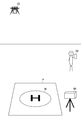
- FIG. 2 is a diagram showing how the unmanned aerial vehicle 20 lands.
- the port P is arranged on the ground, and the detection device 40 is arranged in the vicinity thereof.
- a plurality of detection devices 40 may be arranged so as to surround the port P.
- a communication device such as a Wi-Fi access point may be arranged near the port P.
- Port P is a place prepared for at least one of landing and takeoff.
- the port P may be fixed such as a concrete foundation or a rooftop of a building, or may be portable such as a mat, a sheet, and a plate.
- the unmanned aerial vehicle 20 that can be used for the port P may be predetermined, and for example, the usage time of each of the plurality of unmanned aerial vehicles 20 may be predetermined.
- the detection device 40 is arranged at a position where part or all of the port P is within the detection range. In other words, the position and orientation of the detection device 40 are determined so that part or all of the port P can be detected.
- the detection range is a range that can be detected by the detection device 40. In the present embodiment, since the detection device 40 is a camera, the detection range is the shooting range (within the angle of view) of the camera. If the detection device 40 is an infrared sensor, an ultrasonic sensor, or the like, the detection range is a range where infrared rays, ultrasonic waves, or the like reach.
- the detection range of the detection device 40 includes the port P and its surroundings
- the imaging range may be only inside the port P.
- the periphery is an area around the port P, and is, for example, an area outside the port P that is less than a predetermined distance from the port P.
- a case will be described in which the area excluding the port P in the detection range of the detection device 40 (that is, the part of the captured image where the port P is not shown) corresponds to the surrounding area. Only a part may correspond to the surroundings.
- the user waits for the unmanned aerial vehicle 20 to arrive near the port P or at a position separated by a certain distance or more.
- an application hereinafter referred to as a flight management application
- the flight management application for notifying the current position of the unmanned aerial vehicle 20 and the like is installed in the user terminal 30, and the user activates the flight management application. Then, the flight status of the unmanned aerial vehicle 20 is grasped.
- the flight management application may be capable of tracking the current position of the unmanned aerial vehicle 20 in real time, or may notify the estimated arrival time of the unmanned aerial vehicle 20. Further, for example, when the unmanned aerial vehicle 20 flies to a position less than a predetermined distance (for example, 100 meters) from the port P as in the second embodiment described later, a message or the like notifying whether landing is possible or the like is notified. May be.
- a predetermined distance for example, 100 meters
- the unmanned aerial vehicle 20 may fly without holding any cargo, but in the present embodiment, the unmanned aerial vehicle 20 flies to port P while holding cargo.
- Freight is an object to be transported, and is an object that the unmanned aerial vehicle 20 transports from a starting point to a destination. Freight is sometimes called luggage.
- the freight is a product ordered by the user, a mail item to the user, or materials and tools used by the user for work.
- the unmanned aerial vehicle 20 has a holding member (for example, a catcher, a cage, a container, or the like) that holds the cargo, and carries the cargo held by the holding member.
- the unmanned aerial vehicle 20 may be operated by the user, but in the present embodiment, the unmanned aerial vehicle 20 autonomously flies on a predetermined route and also autonomously flies during landing and takeoff.
- Autonomous here means that it is computer-based, not user-based.
- the case where the user's operation is not considered at all is included autonomously, and the case where the user's operation is considered auxiliary is also included autonomously.
- the server 10 sets the route of the unmanned aerial vehicle 20, and the server 10 and the unmanned aerial vehicle 20 communicate with each other, whereby the unmanned aerial vehicle 20 autonomously flies.
- Various methods can be applied to the autonomous flight itself, and for example, an autonomous flight algorithm using GPS may be used. Further, the autonomous flight algorithm is mounted on the unmanned aerial vehicle 20, and the unmanned aerial vehicle 20 may fly without communicating with the server 10.
- the port P includes a mark M (a circle including the letter “H” in FIG. 2) that serves as a mark for takeoff and landing.
- the mark M can be used as a target position when landing, or can be used as a position where the unmanned aerial vehicle 20 is placed when taking off.
- the mark M may be any information that can be detected by the imaging unit 24 or the sensor unit 25 of the unmanned aerial vehicle 20, and may be an image such as a logo or an illustration in addition to the characters.
- the cargo collection place is set as the departure point of the unmanned aerial vehicle 20, and the position of the port P is set as the destination.
- the server 10 calculates a flight route from the collection place to the port P, and the unmanned aerial vehicle 20 flies above the port P in the autonomous flight mode based on the flight route.
- the unmanned aerial vehicle 20 arrives above the port P, the landing mode for landing at the port P is changed.
- the unmanned aerial vehicle 20 enters the landing mode, the unmanned aerial vehicle 20 detects the mark M using the imaging unit 24 or the sensor unit 25.
- a known method can be applied to the method of detecting the mark M.
- the unmanned aerial vehicle 20 detects the mark M from the image captured by the image capturing unit 24 using pattern matching, a convolutional neural network, or the like. Further, for example, the unmanned aerial vehicle 20 detects the mark M by using an infrared sensor, an ultrasonic sensor or the like of the sensor unit 25.
- the unmanned aerial vehicle 20 gradually lowers its altitude as it approaches the detected mark M.
- the unmanned aerial vehicle 20 lands on port P, the propeller stops rotating.
- the notification that the landing is completed may be transmitted to the flight management application of the user terminal 30.
- the user moves into the port P and takes out the cargo.
- the unmanned aerial vehicle 20 may drop the cargo onto the port P and take off by opening the holding member using the actuator.
- the unmanned aerial vehicle 20 may be swept by the wind when landing, and may not always land exactly on the mark M. For example, if the wind blows during landing, the unmanned aerial vehicle 20 will disengage from the mark M, so if another cargo is placed near it, the unmanned aerial vehicle 20 may come into contact and fall. In addition, for example, if a gust of wind blows during landing, the unmanned aerial vehicle 20 may extend out of the port P and contact the user or the like. The same applies when the unmanned aerial vehicle 20 takes off from the port P, and there is a possibility that the unmanned aerial vehicle 20 will be touched by the wind and come into contact with the user or the like.
- the unmanned aerial vehicle control system 1 detects the port P and an object in the vicinity thereof based on the captured image captured by the detection device 40, and controls the takeoff and landing. As described in the prior art, if the takeoff and landing is forcibly restricted regardless of the type of the detected object, the takeoff and landing will be restricted more strictly than necessary, resulting in poor flexibility. 1 limits takeoff and landing according to the type of object.
- the control at the time of landing and the control at the time of takeoff will be described in order.
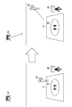
- FIG. 3 and 4 are diagrams showing how landing of the unmanned aerial vehicle 20 is restricted. It should be noted that although the cargo is denoted by the symbol C in FIG. 3, this symbol is omitted unless it is necessary to refer to the drawing.
- the unmanned aerial vehicle 20 when it is detected that another cargo C is present in the port P, the unmanned aerial vehicle 20 has a high probability of contacting the cargo C, so the server 10 does not permit the unmanned aerial vehicle 20 to land. .. In this case, the server 10 hovers the unmanned aerial vehicle 20 in the air and puts it on standby. For example, when the user notices the existence of the cargo C and removes the cargo C from the port P, it is detected that the cargo C has been removed from the port P, and the unmanned aerial vehicle 20 is allowed to land.
- the user may move the cargo C to a place away from the port P, but the size of the cargo C is smaller than that of a human being or an automobile, so that the unmanned aerial vehicle 20 is greatly swung out of the port P.
- the probability of contact is low. Even if the unmanned aerial vehicle 20 goes out of the port P and comes into contact with the cargo C, it does not injure humans or animals, and the driver such as a car or a motorcycle is surprised to turn the steering wheel. Nor. Therefore, if the cargo C is moved out of the port P, it is considered that the safety at the time of landing can be sufficiently secured.
- Port P is a place to receive cargo, and it is possible that many cargoes are stacked around it. For this reason, if landing is limited just because there is a cargo C around the port P, a large number of these cargos must be moved to a long distance, resulting in poor flexibility. Therefore, by allowing landing on the cargo C (even if it is not moved to a place away from the port P) on the condition that the cargo C is moved to the outside of the port P, it is possible to save the trouble of carrying the cargo C to a long distance. It is compatible with safety and flexibility.
- the landing of the unmanned aerial vehicle 20 is not permitted as in the case where the cargo C is in the port P.
- the user since the user is larger than the cargo C, even if he/she goes out of the port P, if the user is in the vicinity of the port P and the unmanned aerial vehicle 20 is hit by a gust of wind, the probability of contact is relatively high. .. Further, if the unmanned aerial vehicle 20 contacts the user, the user may be injured and a serious accident may occur. Further, even if the user goes out of the port P, if the user is in the vicinity of the port P, the user may not notice the existence of the unmanned aerial vehicle 20 and enter the port P.
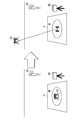
- FIG. 5 and FIG. 6 are views showing how takeoff of the unmanned aerial vehicle 20 is restricted.
- the unmanned aerial vehicle 20 may not only carry the cargo to the port P but also carry the cargo in the port P and carry it to another place. That is, the port P may be used as a departure place as well as a destination. Therefore, as shown in FIG. 5, the unmanned aerial vehicle 20 may be on standby for takeoff with the cargo C loaded.
- the unmanned aerial vehicle 20 may be hit by the wind immediately after takeoff and come into contact with another cargo. Therefore, when a plurality of cargoes are detected in the port P, takeoff may be restricted. However, when it is detected that a plurality of cargoes are in close contact with each other and are stored in the holding member of the unmanned aerial vehicle 20, the unmanned aerial vehicle 20 carries the plurality of cargos at the same time. May be allowed without restrictions on takeoff.
- the unmanned aerial vehicle 20 may contact the user, so takeoff is not permitted. Further, for the same reason as when landing, even if the user goes out of the port P, if the user is in the vicinity of the port P, the unmanned aerial vehicle 20 is likely to come into contact with the user, which may lead to a serious accident. There is also a nature. For this reason, the user is permitted to take off on the condition that the same conditions as when landing are applied and the user moves to a position away from the port P (for example, outside the imaging range of the detection device 40). For the same reason as when landing, even if a strict restriction is set for the user, the flexibility is not so affected, and both safety and flexibility can be achieved.
- the cargo and the user are taken as an example, but landing and landing may be restricted according to the type of object, and similar control may be performed for other types.
- You may For example, when an animal such as a dog or a cat, an automobile, a motorcycle, or the like is detected, the handling may be the same as that of the user. Further, for example, when a cart for carrying the cargo on the ground is detected, the handling may be the same as the cargo.
- the unmanned aerial vehicle control system 1 of the present embodiment does not restrict takeoff and landing more strictly than necessary, but restricts takeoff and landing based on the types of objects in the port P and its surroundings, thereby ensuring safety.
- takeoff and landing are not restricted, and both improvement of safety and improvement of flexibility are achieved.
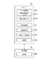
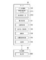
- FIG. 7 is a functional block diagram showing an example of functions implemented by the unmanned aerial vehicle control system 1.
- a detection unit 400 in the unmanned aerial vehicle control system 1, a detection unit 400, a data storage unit 100, a type identification unit 101, a position identification unit 102, a flight mode identification unit 103, and a restriction unit 104 are realized.
- the detection unit 400 is realized by the detection device 40 and each of the other functions is realized by the server 10.
- the detection unit 400 is realized by the detection device 40.
- the detection unit 400 detects an object at a place where at least one of landing and takeoff of the unmanned aerial vehicle 20 is performed.
- the case where the port P and the area around the port P correspond to the location will be described.
- it may be any location where at least one of landing and takeoff of the unmanned aerial vehicle 20 is performed, for example, a parking lot, It may be a riverbed, a park, a residential garden, or the rooftop of a building. That is, it is not a place prepared only for takeoff and landing like the port P, but it is usually used for another purpose, but it may be a place used for takeoff and landing of the unmanned aerial vehicle 20 only at a specific time. ..
- an area for causing the unmanned aerial vehicle 20 to perform at least one of landing and takeoff is determined in advance, and the detection unit 400 uses at least an object within the area and an object around the area. Detect one.
- the port P corresponds to the area
- it may be a predetermined area, for example, an area on which a mat or sheet is laid, an area separated by a tape, a chalk or a color. It may be any area such as an area drawn with a spray or the like, an area surrounded by a color cone (registered trademark), or an area surrounded by a fence.
- the detection unit 400 outputs data indicating the detection result of the object at the port P and its periphery based on the detection signal of the detection device 40.
- the detection unit 400 since the detection device 40 is a camera, the detection unit 400 generates and outputs a captured image showing a state within the imaging range of the detection device 40.
- the captured image means not only a still image but also a moving image.
- FIG. 8 is a diagram showing a captured image output by the detection unit 400. Since the detection device 40 is arranged so as to include the port P and its periphery in the imaging range, the captured image I shows the state of the port P and its periphery as shown in FIG. For example, the area around the port P is an area captured in a portion of the captured image I other than the port P. Note that, hereinafter, the reference numeral of the captured image I will be omitted.
- the data indicating the detection result of the detection unit 400 varies depending on the sensor or the like used as the detection device 40.
- the detection unit 400 includes the detection device 40 that is an infrared sensor. Generate a measured infrared image.
- the detection unit 400 when using the depth sensor, the detection unit 400 generates a depth image measured by the detection device 40 that is the depth sensor.
- the depth image is an image showing the depth of the object (the distance between the depth sensor and the object).
- the data storage unit 100 is realized mainly by the storage unit 12.
- the data storage unit 100 stores data for controlling the unmanned aerial vehicle 20.
- the data storage unit 100 stores the restriction target type data DT1 and the flight management data DT2.
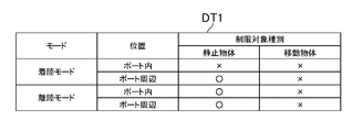
- FIG. 9 is a diagram showing a data storage example of the restriction target type data DT1.
- the restriction target type data DT1 is data indicating the restriction target type.
- the restricted target type is a type of object for which at least one of landing and takeoff is restricted when detected.
- the restricted target type is the type of object to be noted at least at one of landing and takeoff. For example, if even one object of the restriction target type is detected, at least one of landing and takeoff is restricted.
- the content of the restriction target type data DT1 may be changed by an administrator or the like.
- the restricted object type data DT1 includes, for each combination of the flight mode and the position of the object, Restriction target type is defined.
- the restriction target type data DT1 indicates whether each of the stationary object and the moving object corresponds to the restriction target type.
- Stationary object is a stationary object, and as a general rule, it does not move unless it receives a certain force from the outside.
- a stationary object can also be called an object that has no power inside.
- the stationary object is a cargo, a cart that carries the cargo on the ground, a detection device 40, or the like.
- the moving object is a moving object or a movable object.
- a movable object is an object that is stationary at the moment but is movable by its own force without receiving any external force.
- a moving object can also be called an object that has power inside.
- the moving object is a human being, an animal, a car, a motorcycle, a bicycle, or the like.
- the unmanned aerial vehicle 20 if the unmanned aerial vehicle 20 is in the landing mode and the position of the object is within the port P, it will be a restriction target type regardless of whether it is a stationary object or a moving object. Further, for example, if the unmanned aerial vehicle 20 is in the landing mode and the position of the object is around the port P, the stationary object is not the restriction target type, and the moving object is the restriction target type.
- the stationary object is not the restricted target type
- the moving object is the restricted target type.
- the stationary object is not the restriction target type
- the moving object is the restriction target type.
- the restriction target type can be set to any type, For example, it may be subdivided in a stationary object, or subdivided in a moving object.
- the restriction target type may be set not from the viewpoint of whether the object moves or not, but from the viewpoint of whether it is a cargo or an important cargo. Further, for example, the restriction target type may be set from the viewpoint of whether or not it is a living thing.
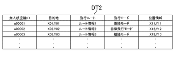
- FIG. 10 is a diagram showing a data storage example of the flight management data DT2.
- the flight management data DT2 is data for managing the unmanned aerial vehicle 20 in flight.
- the flight management data DT2 includes information such as an unmanned aerial vehicle ID that uniquely identifies the unmanned aerial vehicle 20, a destination, a flight route, a current flight mode, and position information indicating a current position. Is stored.
- the unmanned aerial vehicle ID is information such as individual identification information and IP address of the unmanned aerial vehicle 20, and is assumed to be stored in the storage unit 22 or the like of the unmanned aerial vehicle 20.
- the destination is a position where the unmanned aerial vehicle 20 should land, and is, for example, latitude/longitude information or coordinate information of the port P.
- the flight route is route information from the starting point to the destination. The flight route may be set based on the starting point and the destination by using a predetermined route search algorithm such as the Dijkstra method or the Aster method, or may be a straight line connecting the starting point and the destination. Good.
- the current flight mode is the flight mode being set for the unmanned aerial vehicle 20, and any one of a plurality of predetermined flight modes is set.
- any mode can be applied, and in the present embodiment, an autonomous flight mode, a landing mode, and a takeoff mode are prepared, but other flight modes may exist, for example, There may be an evacuation mode of evacuating to a predetermined point, an emergency landing mode in which an attempt is made to land on the spot in an emergency, or a landing completion mode in which landing is completed.
- the autonomous flight mode is a mode in which the vehicle flies on the flight route of the flight management data DT2, and is a flight mode from the takeoff mode to the landing mode.
- the autonomous flight mode is a flight mode from when the unmanned aerial vehicle 20 flies above the departure place to when it reaches the destination.
- the landing mode is a mode for performing a landing operation after the unmanned aerial vehicle 20 reaches the target ground air.
- the takeoff mode is a mode for performing takeoff operation from the state where the unmanned aerial vehicle 20 has landed at the departure point.
- the position information is position information detected by the sensor unit 25 of the unmanned aerial vehicle 20.
- the unmanned aerial vehicle 20 repeatedly detects the position information by the sensor unit 25, and transmits the detected position information to the server 10 together with its own unmanned aerial vehicle ID.
- the server 10 stores the position information in a record of the flight management data DT2 in which the unmanned aerial vehicle ID is stored. This keeps the position information up to date.
- the unmanned aerial vehicle 20 transmits its own unmanned aerial vehicle ID, current position information (that is, position information indicating the position of the departure place), and the destination set for itself to the server 10.
- the destination may be input from a terminal connected to the unmanned aerial vehicle 20. Further, these pieces of information may be transmitted from the terminal to the server 10.
- the server 10 generates a flight route based on the received departure place and destination and stores the information in the flight management data DT2. In this embodiment, the case where the flight mode is set to the takeoff mode at this time will be described, but the takeoff mode may be set when the takeoff is permitted by the restriction unit 104 described later.
- the server 10 transmits information such as a moving direction and a moving speed to the unmanned aerial vehicle 20 together with a takeoff instruction.
- the unmanned aerial vehicle 20 controls the rotation of the propeller and takes off.
- the server 10 is notified of that fact and the flight mode is changed to the autonomous flight mode.
- the unmanned aerial vehicle 20 may take off at its own discretion instead of an instruction from the server 10. After that, by transmitting the position information and the like between the server 10 and the unmanned aerial vehicle 20, autonomous flight to the destination ground sky is realized.
- the flight mode is set to the landing mode.
- the landing mode may be entered when the landing is permitted by the restriction unit 104 described later.
- the server 10 transmits information such as the moving direction and the moving speed to the unmanned aerial vehicle 20 together with the landing instruction.
- the unmanned aerial vehicle 20 may land at its own discretion instead of an instruction from the server 10.
- the unmanned aerial vehicle 20 detects the landing by the pressure-sensitive sensor of the sensor unit 25, the rotation of the propeller is stopped, and the landing is completed. In this case, the unmanned aerial vehicle 20 may notify the server 10 that the landing is completed, and the fact may be stored in the flight management data DT2.
- the type identifying unit 101 is realized mainly by the control unit 11.
- the type identifying unit 101 identifies the type of object based on the detection result of the detecting unit 400. As described above, various methods can be applied to the object detection method itself, and the type identifying unit 101 may identify the type of the object by a method according to the detection method to be used.
- the type identifying unit 101 identifies the type of object based on the captured image generated by the detecting unit 400. For example, pattern data defining patterns such as shapes and colors of various objects is prepared in the data storage unit 100, and the type identifying unit 101 performs pattern matching on a captured image based on the pattern data. The object is detected by this. Further, for example, machine learning such as a convolutional neural network may be used, and the type identifying unit 101 uses a learning device (a learning device that classifies the types of objects) created based on teacher data indicating the characteristics of various objects. The type of the object photographed in the photographed image may be specified by using it.
- a learning device a learning device that classifies the types of objects
- the type identifying unit 101 identifies the type of the object based on the infrared image generated by the detecting unit 400.
- the type identifying unit 101 uses pattern matching or machine learning to identify the type of the object imaged in the infrared image.
- the type identifying unit 101 identifies the type of the object based on the depth image generated by the detecting unit 400.
- the contour of the object can be specified by specifying the edge portion having a large depth difference. Therefore, the type identifying unit 101 extracts the contour line from the depth image and identifies the type of the object from the features of the shape and size of the contour line.
- the type identifying unit 101 identifies, as the type, whether the object is a stationary object that is stationary, or a moving object that is moving or can move.
- a type classified as a stationary object and a type classified as a moving object are defined in advance in the data storage unit 100, and the type identification unit 101 identifies the type identified based on the detection result of the detection unit 400.
- the type identifying unit 101 identifies as a stationary object if the type identified from the captured image or the like is a stationary object, and the type is If it is a person, an animal, or a vehicle, it is specified as a moving object.
- the type identifying unit 101 may identify whether the object is a stationary object or a moving object based on the change in the detection result of the detection unit 400. For example, when a camera is used, a stationary object does not move in principle, so there is no change in continuously captured images. On the other hand, since the moving object moves, the captured image changes. Therefore, the type identifying unit 101 may identify whether the object is a stationary object or a moving object based on the change in the captured image. Also when using the infrared sensor or the depth sensor, the type identifying unit 101 identifies whether the object is a stationary object or a moving object by using the change in the infrared image or the change in the depth image.
- the type identifying unit 101 may identify the type as cargo or non-freight. For example, when using a camera, the shape and color of a cargo or a box are defined in the pattern data, and the type identifying unit 101 performs pattern matching on a captured image based on the pattern data. , Specify whether it is a cargo or a non-cargo. That is, the type identifying unit 101 determines that the type of the object is cargo if it matches the pattern data, and determines that the type of object is other than the cargo if it does not match the pattern data. ..
- a machine learning learning device learns features such as shapes and colors of cargo or boxes, and the type identifying unit learns captured images. You may input into the container and acquire whether the cargo was output as a classification result.
- the type identifying unit 101 identifies whether the cargo is a cargo or a non-cargo based on the characteristics of the infrared image or the depth image.
- the position specifying unit 102 is realized mainly by the control unit 11.
- the position specifying unit 102 specifies the position of the object.
- the position specifying unit 102 specifies the position of the object based on the detection result of the detecting unit 400.
- the position of the object may be detected by a method according to the method of detecting the object.
- the type specifying unit 101 analyzes the captured image to detect an object, and therefore the position specifying unit 102 determines the position where the object is detected in the captured image. (The position of the pixel in which the object is detected in the captured image in FIG. 8) may be acquired.
- the position identifying unit 102 may acquire the position where the object is detected in the infrared image or the depth image.
- the position identifying unit 102 determines whether the position is within the port P or the port P. Specify whether it is the surrounding area.
- the position of the port P (for example, a region in a captured image) is defined in the data storage unit 100 in advance, and the position specifying unit 102 determines whether the specified position is included inside the port P.
- the position of the port P may not be defined in advance, but the position of the port P may be specified from the detection result of the detection unit 400. In this case, similarly to the method of detecting the type of object, the position of the port P in the captured image may be specified by using pattern matching, convolutional neural network, or the like.
- the restriction target type is set according to the position specified by the position specifying unit 102.
- the relationship between the position of the object and the restriction target type is defined, and the restriction target type associated with the position specified by the position specifying unit 102 is set. In the present embodiment, this relationship is defined in the restriction target type data DT1. For example, when the position specifying unit 102 specifies that the position of the object is within the port P, the restriction target type in the port P is set, and the position specifying unit 102 positions the object around the port P. If it is specified, the restriction target type around the port P is set.
- the flight mode specifying unit 103 is realized mainly by the control unit 11.
- the unmanned aerial vehicle 20 flies based on any of a plurality of flight modes, and the flight mode identifying unit 103 identifies the flight mode of the unmanned aerial vehicle 20.
- the flight mode is stored in the flight management data DT2.
- the flight mode is appropriately updated according to the flight situation such as the current position of the unmanned aerial vehicle 20, so the flight mode identifying unit 103 refers to the flight mode stored in the data storage unit 100.
- the type of restriction target is set according to the flight mode.
- the relationship between the flight mode and the restriction target type is defined in the data storage unit 100, and the restriction target type associated with the flight mode specified by the flight mode specifying unit 103 is set. In the present embodiment, this relationship is defined in the restriction target type data DT1. For example, when the flight mode identifying unit 103 identifies the landing mode, the landing mode restriction target type is set, and when the flight mode identifying unit 103 identifies the takeoff mode, The type of restriction target for takeoff mode is set.
- the type of restriction target is set according to whether the unmanned aerial vehicle 20 will land or take off.
- whether to land or take off is specified based on the flight mode.
- it may be specified by another method without being specified by the flight mode. For example, landing may be specified when the unmanned aerial vehicle 20 in flight arrives at a destination (eg, above port P). Further, for example, it may be specified to take off when a destination, a flight route, or the like is set in a state where the propeller of the unmanned aerial vehicle 20 is not rotating. It should be noted that it is not necessary that the restriction target types are completely different at the time of landing and at the time of takeoff, as long as at least a part of them is different.
- the landing mode is specified by the flight mode specifying unit 103 (that is, when the unmanned aerial vehicle 20 is landing)
- the object is in the port, all types are It is set as the restriction target type, and if the object is around the port, the moving object is set as the restriction target type.
- the takeoff mode is specified by the flight mode specifying unit 103 (that is, when the unmanned aerial vehicle 20 takes off)
- the moving object is set as the restriction target type regardless of the position of the object.
- the limiting unit 104 is realized mainly by the control unit 11.
- the restriction unit 104 restricts at least one of landing and takeoff of the unmanned aerial vehicle 20, based on the type identified by the type identifying unit 101. In the present embodiment, both landing and takeoff are targeted for processing by the limiting unit 104, but the limiting unit 104 may target only one of landing and takeoff.
- -Limiting landing means not landing or not allowing landing. For example, hovering the unmanned aerial vehicle 20 to make it stand by on the spot, do not shift to the landing mode, increase the altitude, do not reduce the rotation speed of the propeller, keep the rotation speed of the propeller above a threshold value. , Or moving away from the port P corresponds to limiting landing.
- -Limiting take-off means not taking off or permitting take-off. For example, keeping the unmanned aerial vehicle 20 landed, not transitioning to takeoff mode, not increasing altitude, not increasing the speed of rotation of the propeller, keeping the speed of rotation of the propeller below a threshold, or Staying on port P is equivalent to limiting takeoff.
- the restriction unit 104 restricts at least one of landing and takeoff of the unmanned aerial vehicle when the type specified by the type specifying unit 101 is a predetermined restriction target type. To do. For example, the restriction unit 104 determines whether or not the type specified by the type specifying unit 101 is a restriction target type, and restricts the landing and takeoff of the unmanned aerial vehicle 20. In the present embodiment, when at least one object of the restriction target type is detected, the restriction unit 104 performs landing and takeoff of the unmanned aerial vehicle 20 even if other detected objects do not correspond to the restriction target type. To limit.
- the restriction unit 104 determines that the type specified by the type specifying unit 101 is at landing. It is determined whether or not it is the restriction target type and the landing of the unmanned aerial vehicle 20 is restricted when it is determined that it is the restriction target type at the time of landing. Further, for example, when the unmanned aerial vehicle 20 is in the takeoff mode, the limiting unit 104 determines whether the type specified by the type specifying unit 101 is the restriction target type at the time of takeoff, and is the restriction target type at the time of takeoff. When it is determined that the takeoff of the unmanned aerial vehicle 20 is restricted.
- the restriction unit 104 restricts at least one of landing and takeoff of the unmanned aerial vehicle 20, based on whether the object specified by the type specifying unit 101 is a stationary object or a moving object. For example, the limiting unit 104 limits the landing of the unmanned aerial vehicle 20 if the object specified by the type specifying unit 101 is a stationary object and is within the port P, and the object is in the vicinity of the port P. If so, the unmanned aerial vehicle 20 is allowed to land without restriction. Further, for example, when the object specified by the type specifying unit 101 is a moving object, the landing of the unmanned aerial vehicle 20 is restricted regardless of the position of the object.
- the restriction unit 104 permits takeoff of the unmanned aerial vehicle 20 without restriction, regardless of the position of the object. Further, for example, when the object specified by the type specifying unit 101 is a stationary object, the takeoff of the unmanned aerial vehicle 20 is restricted regardless of the position of the object.
- the restriction unit 104 may restrict at least one of landing and takeoff of the unmanned aerial vehicle based on whether the object identified by the type identifying unit 101 is cargo or something other than cargo. For example, when the object identified by the type identifying unit 101 is a cargo, and the cargo is in the port P, the restriction unit 104 restricts the landing of the unmanned aerial vehicle 20, and the cargo may be in the vicinity of the port P. For example, the landing of the unmanned aerial vehicle 20 is allowed without restriction. Further, for example, when the object specified by the type specifying unit 101 is other than a cargo, the landing of the unmanned aerial vehicle 20 is restricted regardless of the position of the object.
- the restriction unit 104 permits the unmanned aircraft 20 to take off without restriction regardless of the position of the cargo. Further, for example, when the object specified by the type specifying unit 101 is other than a cargo, the takeoff of the unmanned aerial vehicle 20 is restricted regardless of the position of the object.
- the restriction unit 104 restricts at least one of landing and takeoff of the unmanned aerial vehicle 20 based on the position specified by the position specifying unit 102. For example, it is assumed that the data storage unit 100 defines a position where the landing of the unmanned aerial vehicle 20 should be restricted and a position where the takeoff of the unmanned aerial vehicle 20 should be restricted.
- the restriction unit 104 determines whether or not the position specified by the position specifying unit 102 is a position at which landing should be restricted, and the position specified by the position specifying unit 102 is determined as a position at which landing should be restricted. If so, the landing of the unmanned aerial vehicle 20 is restricted.
- the limiting unit 104 determines whether the position specified by the position specifying unit 102 is a position where the takeoff should be restricted, and judges that the position specified by the position specifying unit 102 is a position where the takeoff should be restricted. If so, the takeoff of the unmanned aerial vehicle 20 is restricted.
- the limiting unit 104 determines whether the object identified by the type identifying unit 101 is inside the port P or around the port P. Restrict at least one of unmanned aerial vehicle landing and takeoff. For example, the limiting unit 104 determines whether or not the position specified by the position specifying unit 102 is within the port P. For example, when the position is within the port P, the restriction unit 104 restricts landing regardless of the type of object. Further, for example, when the position is in the vicinity of the port P, the restriction unit 104 permits landing without restriction if it is a stationary object, and restricts landing if it is a moving object.
- the unmanned aerial vehicle 20 can carry cargo, and the restriction target type may be cargo.
- the limiting unit 104 does not limit the takeoff of the unmanned aerial vehicle 20 even if the cargo is identified by the type identifying unit 101.
- the restriction unit 104 restricts the landing of the unmanned aerial vehicle 20 when the type identification unit 101 identifies the cargo.
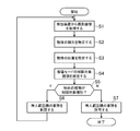
- FIG. 11 is a flow chart showing an example of processing at the time of landing.
- the process of FIG. 11 is executed when the flight mode becomes the landing mode.
- the control unit 11 acquires a captured image from the detection device 40 (S1).
- the detection device 40 continuously captures images based on a predetermined frame rate and transmits the captured images to the server 10.
- the server 10 receives the captured image transmitted by the detection device 40.
- the control unit 11 identifies the type of object based on the captured image acquired in S1 (S2).
- the control unit 11 uses pattern matching or a convolutional neural network to detect an object photographed in a photographed image and specify its type.
- the control unit 11 specifies the position of the object whose type is specified in S2 (S3).
- the control unit 11 specifies the position where the object is detected in the captured image. For example, when the position in the photographed image is indicated by the two-dimensional coordinate of the screen coordinate system limited to the upper left of the photographed image, the control unit 11 identifies the two-dimensional coordinate indicating the position where the object is detected in S2. To be done.
- the control unit 11 sets the landing mode restricted target type according to the position of the object identified in S3 based on the restricted target type data DT1 (S4).
- the control unit 11 determines whether the position in the captured image identified in S3 is within the port P. Since the position of the detection device 40 is fixed in advance and the area where the port P appears in the captured image is also known in advance, the control unit 11 includes the two-dimensional coordinates indicating the position of the object specified in S3 in the area. Is determined. Then, when it is determined that the position of the identified object is within the port P, the control unit 11 sets both the stationary object and the moving object as the restriction target types. On the other hand, when it is determined that the position of the specified object is around the port P, the control unit 11 sets the moving object as the restriction target type.
- the control unit 11 determines whether or not the type of object is the restriction target type set in S4 (S5). In S5, when the position of the object is within the port P, the control unit 11 determines that the type is the restriction target type regardless of the type specified in S3. In addition, when the position of the object is around the port P, the control unit 11 determines that the type specified in S3 is the moving object and is the restriction target type.
- control unit 11 restricts the landing of the unmanned aerial vehicle 20 (S6).
- control unit 11 transmits an instruction to hover on the spot to unmanned aerial vehicle 20.
- the unmanned aerial vehicle 20 hovers on the spot and waits for landing.
- control unit 11 permits the unmanned aerial vehicle 20 to land (S7), and this processing ends.
- control unit 11 transmits an instruction to permit unmanned aerial vehicle 20 to land.
- the unmanned aerial vehicle 20 detects the mark M in the port P based on the detection signal of the image capturing unit 24 or the sensor unit 25, and moves to approach the mark M and lands.
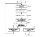
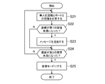
- FIG. 12 is a flowchart showing an example of processing at the time of takeoff.
- the process of FIG. 12 is executed when the flight mode becomes the takeoff mode.
- the processing of S11 to S13 is the same as the processing of S1 to S3, respectively.
- the control unit 11 sets the takeoff mode limitation target type according to the position of the object identified in S12 based on the limitation target type data DT1 (S14).
- the process of S14 is substantially similar to the process of S4, but differs from S4 in that the restriction target type of the takeoff mode of the restriction target type data DT1 is referred to.
- the moving object is set as the restriction target type regardless of the position of the object, but the restriction target type may be set according to the position of the object even at the time of takeoff.
- the control unit 11 determines whether or not the type of the object is the restriction target type (S15). In S15, if the object type is a stationary object, the control unit 11 determines that it is not a restriction target type, and if the object type is a moving object, it determines that it is a restriction target type.
- control unit 11 limits the takeoff of the unmanned aerial vehicle 20 (S16). In S16, control unit 11 does not transmit to unmanned aerial vehicle 20 an instruction to rotate the propeller.
- the control unit 11 permits the takeoff of the unmanned aerial vehicle 20 (S17), and this processing ends.
- the control unit 11 transmits to the unmanned aerial vehicle 20 an instruction to permit takeoff.
- the unmanned aerial vehicle 20 rotates the propeller and takes off.
- the takeoff and landing is not strictly limited more than necessary, but the takeoff and landing is limited based on the type of the object in the port P and its surroundings. In the case of an object that does not affect the safety, takeoff and landing are not limited, and both improvement of safety and improvement of flexibility can be achieved.
- the takeoff and landing of the unmanned aerial vehicle 20 is controlled based on whether the port P and the objects in the vicinity thereof are stationary objects or moving objects. For example, the probability of contact is low and the influence at the time of contact is relatively small. In the case of an object, flexibility is ensured without limiting takeoff and landing, and in the case of a moving object that has a high probability of contact and the impact of contact is relatively large, safety is limited by taking off and landing. It is possible to improve the safety and the flexibility more effectively.
- the takeoff and landing of the unmanned aerial vehicle 20 is controlled based on whether the port P and the objects in the vicinity thereof are cargo or non-cargo, and, for example, the probability of contact is low and the effect of contact is relatively small.
- flexibility is ensured without limiting takeoffs and landings, and in the case of other objects that have a high probability of contact and the impact of contact is relatively large, safety is limited by takingoff and landing. It is possible to improve the safety and the flexibility more effectively.
- the object not only in the port P but also in the vicinity of the port P is carefully taken off and landed. Can be controlled.
- the takeoff and landing of the unmanned aerial vehicle 20 based on the position of the port P or an object in the vicinity of the port P, for example, when there is a cargo in the port P, landing is restricted and safety is emphasized.
- landing is restricted and safety is emphasized.
- the takeoff and landing of the unmanned aerial vehicle 20 is restricted based on whether the position of the object is within the port P or the vicinity of the port P. For example, when the cargo is in the port P, the landing is restricted.
- Safety and if there is a cargo around Port P, it is possible to emphasize flexibility without restricting landing, and to improve safety and flexibility more effectively. You can
- the restricted target type according to the flight mode, for example, it is possible to deal with the case where the type of the object to be noted differs depending on the flight mode, and further improve safety and flexibility. It is possible to achieve both effectively.
- the restriction target type is set according to whether the unmanned aerial vehicle 20 performs landing or takeoff, so that it is possible to cope with, for example, a case where the types of objects to be noted are different at landing and at takeoff. Therefore, the improvement of safety and the improvement of flexibility can be more effectively achieved at the same time.
- the unmanned aerial vehicle 20 takes off, even if the cargo is specified, it does not affect the takeoff. Therefore, the flexibility is emphasized and the takeoff is not limited. If specified, it will affect the landing, so by limiting the landing with emphasis on safety, it is possible to more effectively improve both safety and flexibility.
- a second embodiment of the unmanned aerial vehicle control system 1
- the unmanned aerial vehicle 20 when the unmanned aerial vehicle 20 is landing, if there is a cargo on the port P or a user is at or around the port P, the landing of the unmanned aerial vehicle 20 may be hindered. is there. Therefore, in the second embodiment, in order to prepare for the unmanned aerial vehicle 20 to land smoothly, in the present embodiment, a predetermined message is transmitted to the user when the unmanned aerial vehicle 20 approaches the arrival. ing.
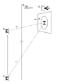
- FIG. 13 is a diagram showing how the unmanned aerial vehicle 20 moves toward the port P.
- a first threshold value for example, 100 meters
- the server 10 causes the user terminal to operate.
- a predetermined message is transmitted to 30.
- the straight line distance L between the unmanned aerial vehicle 20 and the port P is shown in FIG. 13, the distance in the horizontal direction may be used without considering the altitude difference between them.
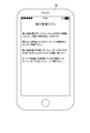
- FIG. 14 is a diagram showing an example of a message transmitted to the user terminal 30.
- the message may be displayed using any medium such as e-mail, SNS, message application, or push notification.
- the flight management application displays a message indicating that the unmanned aerial vehicle 20 is approaching.
- the content of the message is not limited to the example of FIG. 14, and, for example, before the unmanned aerial vehicle 20 arrives above the port P, the restriction unit 104 determines in advance whether landing is possible, and the determination result by the restriction unit 104. May be displayed as a message.
- the server 10 changes the unmanned aerial vehicle 20 to the landing mode. Will be notified.
- the unmanned aerial vehicle 20 changes from the autonomous flight mode to the landing mode. The operation after changing to the landing mode is as described in the first embodiment.
- the server 10 is responsive to each of the unmanned aerial vehicle 20 and the user terminal 30 regardless of the distance between the unmanned aerial vehicle 20 and the port P.
- Information for notifying takeoff may be notified, and if takeoff is permitted, a control signal for taking off may be transmitted.
- FIG. 15 is a functional block diagram of the second embodiment. As shown in FIG. 15, in the second embodiment, in addition to the functions described in the first embodiment, the positional relationship identifying unit 105 and the transmitting unit 106 are realized. In this embodiment, a case where these functions are realized in the server 10 will be described.
- the positional relationship specifying unit 105 is realized mainly by the control unit 11.
- the positional relationship identifying unit 105 identifies the positional relationship between the unmanned aerial vehicle 20 in flight and the port P.
- the position of the unmanned aerial vehicle 20 is shown in the position information of the flight management data DT2, and the position of the port P is shown in the destination of the flight management data DT2.
- the positional relationship is specified based on DT2.
- the positional relationship is the relative position of the unmanned aerial vehicle 20 with respect to the port P, and may be, for example, the distance between the unmanned aerial vehicle 20 and the port P, or the angle of the unmanned aerial vehicle 20 with respect to the port P (the unmanned aerial vehicle 20 and the port P). Angle formed by the straight line connecting the line and the ground plane, or both of them.
- the positional relationship identifying unit 105 identifies the distance between the unmanned aerial vehicle 20 in flight and the place as the positional relationship. The positional relationship identifying unit 105 will calculate the distance between the position indicated by the positional information of the unmanned aerial vehicle 20 and the position of the port P. As described above, the distance may be a distance on a three-dimensional space or a distance on a horizontal plane.
- the transmission unit 106 is realized mainly by the control unit 11.
- the transmission unit 106 transmits information according to the positional relationship to a destination according to the positional relationship specified by the positional relationship specifying unit 105.
- the relationship between the positional relationship and the destination and the type of information is assumed to be stored in the data storage unit 100 in advance.
- the transmission unit 106 transmits the type of information associated with the positional relationship to the destination associated with the positional relationship specified by the positional relationship specifying unit 105 based on the relationship.
- the transmission unit 106 since the distance is acquired as the positional relationship, transmits the information according to the distance to the destination according to the distance specified by the positional relationship specifying unit 105.
- the relationship between the distance and the destination and the type of information is stored in advance in the data storage unit 100, and the transmission unit 106 determines that the distance specified by the positional relationship specifying unit 105 is based on the relationship.
- the type of information associated with the distance is transmitted to the associated destination.
- the transmission unit 106 transmits the first information to the first destination when the distance between the unmanned aerial vehicle 20 and the port P becomes less than the first threshold value, and the unmanned aerial vehicle 20 and the port P are communicated with each other.
- the second information is transmitted to the second transmission destination.
- the first threshold value and the second threshold value are stored in advance in the data storage unit 100 and can be changed by an administrator or the like.
- the first threshold value and the second threshold value may be set for any purpose.
- the first threshold value is a threshold value indicating the timing at which the user should be notified that the unmanned aerial vehicle 20 is approaching.
- the second threshold is a threshold indicating the timing at which the process of restricting the landing of the unmanned aerial vehicle 20 should be executed.
- the first threshold is a distance of several tens of meters to several kilometers
- the second threshold is a distance of several meters to several tens of meters.
- the difference between the first threshold value and the second threshold value may be a distance that can secure a sufficient time (for example, about 1 to 10 minutes) to confirm a message or the like with the user.
- the transmission unit 106 transmits a predetermined message to the user terminal when the distance between the unmanned aerial vehicle 20 and the port P is less than the first threshold.
- the data indicating the content of the message is stored in advance in the data storage unit 100, and the transmission unit 106 generates and transmits the message based on the data.
- the content of the message may be any content, for example, content indicating that the unmanned aerial vehicle 20 is approaching the arrival of the unmanned aerial vehicle 20.
- the transmission unit 106 transmits a control signal based on the restriction unit 104 to the unmanned aerial vehicle 20 when the distance between the unmanned aerial vehicle 20 and the port P is less than the second threshold value.
- the control signal based on the restriction unit 104 is a signal indicating that landing is not permitted or a signal indicating that landing is permitted.
- the transmitting unit 106 transmits a signal indicating that landing is not permitted or a signal indicating that hovering is to be performed on the spot when the landing is not permitted by the limiting unit 104.
- the transmission unit 106 transmits a signal indicating that the landing is permitted when the landing is permitted by the restriction unit 104.
- the transmission unit 106 transmits an instruction to the landing mode when the landing is permitted by the restriction unit 104.
- the transmission unit 106 may transmit information to a device other than the user terminal 30, for example, the unmanned aerial vehicle 20.
- the deceleration instruction may be transmitted to the detection device 40 or the activation instruction may be transmitted to the detection device 40.
- the transmission unit 106 may transmit information to a device other than the unmanned aerial vehicle 20, for example, the user terminal.
- a predetermined message may be transmitted to 30, or an activation instruction may be transmitted to the detection device 40.
- the transmission unit 106 may transmit a message to a terminal arranged at the port P when the distance from the port P is less than the first threshold value or less than the second threshold value, An instruction to turn on the lighting arranged near the port P may be transmitted.
- the transmission unit 106 does not particularly transmit information to the user terminal 30 when the distance is equal to or greater than the threshold, and transmits information such as a message to the user terminal 30 when the distance is less than the threshold. Good.
- the transmission destination to which the transmission unit 106 transmits information may be any of the unmanned aerial vehicle 20, the user terminal 30, or the detection device 40, or another computer such as a terminal arranged at the port P. It may be. Further, for example, the transmission unit 106 may transmit any of the above-described information, and in addition, a command requesting the remaining battery level of the unmanned aerial vehicle 20, a request to activate the videophone function of the user terminal 30, Alternatively, a request for changing the detection condition of the detection device 40 or the like may be transmitted.
- FIG. 16 is a diagram showing processing executed in the second embodiment.
- the processing described below is executed by the control unit 11 operating according to the program stored in the storage unit 12. Note that the process described below is an example of the process of the functional block illustrated in FIG. 16.
- control unit 11 calculates the distance between the unmanned aerial vehicle 20 and the port P based on the flight management data DT2 (S21).
- control unit 11 calculates the distance between the position indicated by the position information of unmanned aerial vehicle 20 stored in flight management data DT2 and the destination.
- the control unit 11 determines whether the distance calculated in S21 is less than the first threshold value (S22). It is assumed that the first threshold value is stored in the storage unit 12 in advance. When it determines with it being less than a 1st threshold value (S22;Y), the control part 11 transmits a message to the user terminal 30 (S23). The message is stored in the storage unit 12 in advance.
- the control unit 11 determines whether the distance calculated in S21 is less than the second threshold value (S24).
- the second threshold is assumed to be stored in the storage unit 12 in advance.
- the control unit 11 transmits a notification to the unmanned aerial vehicle 20 to the landing mode (S25), and this processing ends. After that, the processing of FIG. 11 described in the first embodiment is executed.
- the server 10 by transmitting information according to the positional relationship between the unmanned aerial vehicle 20 and the port P to the destination according to the positional relationship, for example, the unmanned aerial vehicle 20 and the port
- the server 10 transmits the flight status of the unmanned aerial vehicle 20 to the user terminal 30, and when it is in another positional relationship, the server 10 transmits a predetermined signal to the unmanned aerial vehicle 20. Therefore, it is possible to improve convenience when flying the unmanned aerial vehicle 20.
- the server 10 transmits the flight status of the unmanned aerial vehicle 20 to the user terminal 30, and when the unmanned aerial vehicle 20 further approaches the port P, the server 10 sends a predetermined signal to the unmanned aerial vehicle 20. Can be transmitted, and the convenience of flying the unmanned aerial vehicle 20 can be improved.
- the first information is transmitted to the first destination, and when the distance is less than the second threshold.
- the second information By transmitting the second information to the second destination, the convenience of flying the unmanned aerial vehicle 20 can be improved.
- a predetermined message is transmitted to the user terminal 30, and when the distance is less than the second threshold value, By transmitting a control signal indicating permission for takeoff and landing to unmanned aerial vehicle 20, it is possible to improve convenience when flying unmanned aerial vehicle 20.
- takeoff and landing may not be limited as in the first embodiment.
- the server 10 transmits a predetermined message to the user terminal 30, and the distance becomes less than the second threshold.
- the server 10 may instruct the unmanned aerial vehicle 20 to shift to the landing mode without the restriction unit 104 executing the restriction.
- the user can give time to remove the cargo on the port P or call attention to the surroundings by receiving the message in advance, so that the safety can be improved. Since the landing of the unmanned aerial vehicle 20 is not limited, the flexibility can be improved.
- the server 10 identifies the flight mode of the unmanned aerial vehicle 20 based on the flight management data DT2, and transmits the type information associated with the flight mode to the destination associated with the identified flight mode.
- the server 10 may have different destinations and types of information in the landing mode and the takeoff mode.
- the unmanned aerial vehicle 20 does not have to carry a cargo.
- the unmanned aerial vehicle 20 may fly for various purposes.
- the unmanned aerial vehicle 20 may fly for purposes such as photographing, detecting weather information, security, or spraying pesticides.
- the unmanned aerial vehicle control system 1 may include another computer (for example, a server computer or a personal computer), and the flight control of each unmanned aerial vehicle 20 may be executed by the computer.
- the data storage unit 100 may be realized by a database server in the unmanned aerial vehicle control system 1 or a database server outside the unmanned aerial vehicle control system 1.
- each function described above may be realized by any computer of the unmanned aerial vehicle control system 1, and each function may be realized by a plurality of computers such as the server 10, the unmanned aerial vehicle 20, and the user terminal 30. It may be shared.
Landscapes
- Engineering & Computer Science (AREA)
- Aviation & Aerospace Engineering (AREA)
- Physics & Mathematics (AREA)
- General Physics & Mathematics (AREA)
- Automation & Control Theory (AREA)
- Radar, Positioning & Navigation (AREA)
- Remote Sensing (AREA)
- Mechanical Engineering (AREA)
- Acoustics & Sound (AREA)
- Traffic Control Systems (AREA)
Abstract
Selon la présente invention, un moyen de détection (400) d'un système de commande de véhicule aérien sans pilote (1) détecte un objet à un emplacement où au moins l'un parmi l'atterrissage et le décollage d'un véhicule aérien sans pilote (20) est réalisé. Un moyen de spécification de type (101) spécifie le type de l'objet, sur la base du résultat de détection du moyen de détection (400). Un moyen de restriction (104) limite au moins l'un parmi l'atterrissage et le décollage du véhicule aérien sans pilote (20), sur la base du type spécifié par le moyen de spécification de type (101).
Priority Applications (3)
| Application Number | Priority Date | Filing Date | Title |
|---|---|---|---|
| US15/734,227 US11816999B2 (en) | 2018-12-25 | 2018-12-25 | Unmanned aerial vehicle control system, unmanned aerial vehicle control method, and program |
| PCT/JP2018/047480 WO2020136703A1 (fr) | 2018-12-25 | 2018-12-25 | Système et procédé de commande de véhicule aérien sans pilote, et programme |
| JP2020502248A JP6748797B1 (ja) | 2018-12-25 | 2018-12-25 | 無人航空機制御システム、無人航空機制御方法、及びプログラム |
Applications Claiming Priority (1)
| Application Number | Priority Date | Filing Date | Title |
|---|---|---|---|
| PCT/JP2018/047480 WO2020136703A1 (fr) | 2018-12-25 | 2018-12-25 | Système et procédé de commande de véhicule aérien sans pilote, et programme |
Publications (1)
| Publication Number | Publication Date |
|---|---|
| WO2020136703A1 true WO2020136703A1 (fr) | 2020-07-02 |
Family
ID=71126976
Family Applications (1)
| Application Number | Title | Priority Date | Filing Date |
|---|---|---|---|
| PCT/JP2018/047480 Ceased WO2020136703A1 (fr) | 2018-12-25 | 2018-12-25 | Système et procédé de commande de véhicule aérien sans pilote, et programme |
Country Status (3)
| Country | Link |
|---|---|
| US (1) | US11816999B2 (fr) |
| JP (1) | JP6748797B1 (fr) |
| WO (1) | WO2020136703A1 (fr) |
Families Citing this family (10)
| Publication number | Priority date | Publication date | Assignee | Title |
|---|---|---|---|---|
| WO2019140699A1 (fr) | 2018-01-22 | 2019-07-25 | SZ DJI Technology Co., Ltd. | Procédés et système pour suivi multi-cible |
| CN112052918B (zh) * | 2019-06-05 | 2022-05-10 | 华为技术有限公司 | 一种无人机身份标识模组及存储方法 |
| CN110262559B (zh) * | 2019-07-18 | 2022-11-08 | 深圳市道通智能航空技术股份有限公司 | 一种无人机安全保护方法、装置及无人机 |
| US11422572B2 (en) * | 2020-10-20 | 2022-08-23 | DroneUp, LLC | Methods and apparatus for navigating an unmanned vehicle based on a calculation of relative distance differences between a start location and a designated drop location |
| JP7522007B2 (ja) * | 2020-10-30 | 2024-07-24 | 川崎重工業株式会社 | 無人配送システム及び無人配送方法 |
| US11797029B2 (en) * | 2021-07-19 | 2023-10-24 | Ford Global Technologies, Llc | Systems and methods for operating drones in proximity to objects |
| US12372975B2 (en) * | 2022-04-27 | 2025-07-29 | Snap Inc. | Unlocking an autonomous drone for takeoff |
| KR102539970B1 (ko) * | 2022-06-24 | 2023-06-05 | (주)쿼터니언 | 이륙조건을 자동으로 감지하여 이륙조건이 적합하지않으면 스테이션에서 운용하는 드론의 이륙을 강제로 방지하는 드론 스테이션 시스템 |
| US20250341840A1 (en) * | 2024-05-02 | 2025-11-06 | Wisk Aero Llc | Land hazard communication between a landing site and a pilotless aircraft |
| IL314159B2 (en) * | 2024-06-30 | 2026-03-01 | Israel Aerospace Ind Ltd | Anchoring a UAV to the orbit |
Citations (2)
| Publication number | Priority date | Publication date | Assignee | Title |
|---|---|---|---|---|
| WO2010137596A1 (fr) * | 2009-05-26 | 2010-12-02 | 国立大学法人 千葉大学 | Dispositif de commande de corps mobile et corps mobile dans lequel est monté un dispositif de commande de corps mobile |
| JP2017523087A (ja) * | 2014-08-11 | 2017-08-17 | アマゾン テクノロジーズ インコーポレイテッド | 自動航空機のプロペラ安全性 |
Family Cites Families (14)
| Publication number | Priority date | Publication date | Assignee | Title |
|---|---|---|---|---|
| US6974077B1 (en) * | 2004-09-09 | 2005-12-13 | Edward Beyder | Method of remote picking-up of soiled laundry and delivering clean laundry with on-site yet remote weighing |
| US10466700B1 (en) * | 2015-09-25 | 2019-11-05 | Amazon Technologies, Inc. | Detecting of navigation data spoofing based on signal strength variance |
| GB2564804B (en) * | 2016-05-04 | 2021-04-21 | Walmart Apollo Llc | Systems and methods for transporting products via unmanned aerial vehicles |
| US9984579B1 (en) * | 2016-06-28 | 2018-05-29 | Amazon Technologies, Inc. | Unmanned aerial vehicle approach notification |
| US10029787B1 (en) * | 2016-06-30 | 2018-07-24 | X Development Llc | Interactive transport services provided by unmanned aerial vehicles |
| US10395544B1 (en) * | 2016-08-29 | 2019-08-27 | Amazon Technologies, Inc. | Electronic landing marker |
| US10497129B1 (en) * | 2016-08-31 | 2019-12-03 | Amazon Technologies, Inc. | Image-based weather condition detection |
| US10198955B1 (en) * | 2016-09-08 | 2019-02-05 | Amazon Technologies, Inc. | Drone marker and landing zone verification |
| US10248120B1 (en) * | 2016-09-16 | 2019-04-02 | Amazon Technologies, Inc. | Navigable path networks for autonomous vehicles |
| US10370093B1 (en) * | 2016-11-16 | 2019-08-06 | Amazon Technologies, Inc. | On-demand drone noise measurements |
| US11308813B2 (en) | 2017-02-27 | 2022-04-19 | The University Of Tokyo | Flight management system |
| WO2019152384A1 (fr) * | 2018-01-31 | 2019-08-08 | Walmart Apollo, Llc | Système et procédé pour défendre un véhicule aérien sans pilote contre des menaces au sol |
| US11132881B2 (en) * | 2018-05-08 | 2021-09-28 | Amazon Technologies, Inc. | Electronic devices capable of communicating over multiple networks |
| US11127071B2 (en) * | 2018-09-17 | 2021-09-21 | International Business Machines Corporation | Drone station marketplace |
-
2018
- 2018-12-25 WO PCT/JP2018/047480 patent/WO2020136703A1/fr not_active Ceased
- 2018-12-25 JP JP2020502248A patent/JP6748797B1/ja active Active
- 2018-12-25 US US15/734,227 patent/US11816999B2/en active Active
Patent Citations (2)
| Publication number | Priority date | Publication date | Assignee | Title |
|---|---|---|---|---|
| WO2010137596A1 (fr) * | 2009-05-26 | 2010-12-02 | 国立大学法人 千葉大学 | Dispositif de commande de corps mobile et corps mobile dans lequel est monté un dispositif de commande de corps mobile |
| JP2017523087A (ja) * | 2014-08-11 | 2017-08-17 | アマゾン テクノロジーズ インコーポレイテッド | 自動航空機のプロペラ安全性 |
Also Published As
| Publication number | Publication date |
|---|---|
| US11816999B2 (en) | 2023-11-14 |
| JPWO2020136703A1 (ja) | 2021-02-15 |
| JP6748797B1 (ja) | 2020-09-02 |
| US20210209954A1 (en) | 2021-07-08 |
Similar Documents
| Publication | Publication Date | Title |
|---|---|---|
| JP6748797B1 (ja) | 無人航空機制御システム、無人航空機制御方法、及びプログラム | |
| US12130636B2 (en) | Methods and system for autonomous landing | |
| US12233859B2 (en) | Apparatus and methods for obstacle detection | |
| US20220357753A1 (en) | Drop-off location planning for delivery vehicle | |
| EP3662335B1 (fr) | Modèle pour déterminer un point de déchargement au niveau d'un emplacement de livraison | |
| US9471059B1 (en) | Unmanned aerial vehicle assistant | |
| US10839336B2 (en) | Unmanned delivery | |
| JP6527299B1 (ja) | 物品受け渡し場所の決定方法、着陸場所の決定方法、物品受け渡しシステム、及び情報処理装置 | |
| CN111051198A (zh) | 无人飞行器控制系统、无人飞行器控制方法、及程序 | |
| US12608931B2 (en) | Generating aerial paths based on properties of aerial image data | |
| CN113853596A (zh) | 更新限制区域数据的方法、装置、可移动平台和计算机存储介质 | |
| JP6637209B1 (ja) | 制御方法、物品受け渡しシステム、着陸システム、及び情報処理装置 | |
| JP7299368B1 (ja) | 無人機、プログラム、情報処理方法及び情報処理システム |
Legal Events
| Date | Code | Title | Description |
|---|---|---|---|
| ENP | Entry into the national phase |
Ref document number: 2020502248 Country of ref document: JP Kind code of ref document: A |
|
| 121 | Ep: the epo has been informed by wipo that ep was designated in this application |
Ref document number: 18945120 Country of ref document: EP Kind code of ref document: A1 |
|
| NENP | Non-entry into the national phase |
Ref country code: DE |
|
| 122 | Ep: pct application non-entry in european phase |
Ref document number: 18945120 Country of ref document: EP Kind code of ref document: A1 |