WO2020136708A1 - 空気調和装置の室外機及び空気調和装置 - Google Patents
空気調和装置の室外機及び空気調和装置 Download PDFInfo
- Publication number
- WO2020136708A1 WO2020136708A1 PCT/JP2018/047506 JP2018047506W WO2020136708A1 WO 2020136708 A1 WO2020136708 A1 WO 2020136708A1 JP 2018047506 W JP2018047506 W JP 2018047506W WO 2020136708 A1 WO2020136708 A1 WO 2020136708A1
- Authority
- WO
- WIPO (PCT)
- Prior art keywords
- fan
- drive source
- outdoor unit
- air conditioner
- conditioner according
- Prior art date
- Legal status (The legal status is an assumption and is not a legal conclusion. Google has not performed a legal analysis and makes no representation as to the accuracy of the status listed.)
- Ceased
Links
Images





Classifications
-
- F—MECHANICAL ENGINEERING; LIGHTING; HEATING; WEAPONS; BLASTING
- F24—HEATING; RANGES; VENTILATING
- F24F—AIR-CONDITIONING; AIR-HUMIDIFICATION; VENTILATION; USE OF AIR CURRENTS FOR SCREENING
- F24F1/00—Room units for air-conditioning, e.g. separate or self-contained units or units receiving primary air from a central station
- F24F1/06—Separate outdoor units, e.g. outdoor unit to be linked to a separate room comprising a compressor and a heat exchanger
- F24F1/38—Fan details of outdoor units, e.g. bell-mouth shaped inlets or fan mountings
-
- F—MECHANICAL ENGINEERING; LIGHTING; HEATING; WEAPONS; BLASTING
- F24—HEATING; RANGES; VENTILATING
- F24F—AIR-CONDITIONING; AIR-HUMIDIFICATION; VENTILATION; USE OF AIR CURRENTS FOR SCREENING
- F24F1/00—Room units for air-conditioning, e.g. separate or self-contained units or units receiving primary air from a central station
- F24F1/06—Separate outdoor units, e.g. outdoor unit to be linked to a separate room comprising a compressor and a heat exchanger
- F24F1/46—Component arrangements in separate outdoor units
Definitions
- the present invention is directed to an outdoor unit and an air conditioner for an air conditioner, which includes a fan disposed at an upper portion and blowing air upward, and a drive source disposed below the fan and connected to the fan via a rotation shaft to rotationally drive the fan.
- a fan disposed at an upper portion and blowing air upward
- a drive source disposed below the fan and connected to the fan via a rotation shaft to rotationally drive the fan.
- the outdoor unit In an outdoor unit of an air conditioner installed in a building or commercial facility, there is a case where the air is exhausted upward from the housing in consideration of the exhaust performance when installed centrally.
- the outdoor unit is provided with a fan guard on the uppermost surface in consideration of safety.
- a fan and a fan motor, which is a drive source, are installed below the fan guard.
- the fan motor is installed below the fan. That is, the outdoor unit includes a fan that is arranged at the top and blows air upward, and a fan motor that is arranged below the fan and is connected to the fan via a rotation shaft to drive the fan to rotate.
- the heat exchanger is arranged on the side surface of the housing below the fan.
- air is taken in from the outside of the side surface of the housing, heat is exchanged by a heat exchanger, and the exhaust air after heat exchange is blown upward by a fan and exhausted.
- the outdoor unit is installed outdoors. Therefore, when the fan is stopped, rain drips inside the housing through the fan guard. Snow accumulates on the fan guard, on the fan or in the enclosure. Even if the outdoor unit is exposed to rain, there is no problem in operating the outdoor unit. However, snow accumulated on the fan guard or on the fan interferes with ventilation or the operation of the fan. Therefore, in an area with a lot of snow, a snow avoidance hood, which is generally called a snow hood, may be installed on the upper part of the housing (for example, refer to Patent Document 1).
- the present invention is for solving the above-mentioned problems, and even when icy rain falls when the fan is stopped, the fan and the driving source are not integrally connected by the icicles and are not fixed to each other, and the fan startup failure occurs. It is an object of the present invention to provide an outdoor unit for an air conditioner and an air conditioner that can prevent a situation in which operation is impossible without doing so.
- An outdoor unit of an air conditioner according to the present invention has a boss portion through which a rotating shaft passes and a blade portion that extends radially outward from the boss portion, a fan that blows upward, and a fan that is disposed below the fan.
- a drive source that is connected to a fan via the rotation shaft to drive the fan to rotate, and an upper surface of the drive source that covers the entire upper surface of the drive source. And a shielding part for avoiding connection.
- the air conditioner according to the present invention includes the outdoor unit of the above air conditioner.
- the shielding unit that covers the entire upper surface of the drive source and avoids the connection of the icicles generated on the lower surface of the boss of the fan to the upper surface of the drive source. Equipped with. For this reason, the shield covers the entire top surface of the drive source, and if icy rain falls when the fan stops, the icicles generated on the bottom surface of the boss of the fan are excluded from the top surface of the drive source through the shield. Therefore, the boss of the fan and the drive source are not integrally connected by ice. Therefore, even when it rains with ice when the fan is stopped, the fan and the driving source are integrally connected by the icicles and are not fixed to each other, so that the fan does not start defectively and the operation cannot be stopped.
- Embodiment 1 is a refrigerant circuit diagram showing an air-conditioning apparatus 100 according to Embodiment 1 of the present invention.
- an outdoor unit 101 and an indoor unit 102 are connected by a gas refrigerant pipe 103 and a liquid refrigerant pipe 104.
- the outdoor unit 101 has a compressor 105, a four-way valve 106, and an outdoor heat exchanger 107.
- the compressor 105 compresses the drawn refrigerant and discharges it. Let the temperature of the refrigerant discharged from the compressor 105 be the discharge temperature. Further, the surface temperature of the discharge pipe of the compressor 105 may be the discharge temperature.
- the compressor 105 may arbitrarily change the operating frequency by, for example, an inverter circuit or the like to change the capacity of the compressor 105 for discharging the refrigerant per unit time.
- the four-way valve 106 is a valve that switches the flow of refrigerant depending on, for example, a cooling operation and a heating operation.
- the outdoor heat exchanger 107 exchanges heat between the refrigerant and the outdoor air.
- the outdoor heat exchanger 107 functions as a condenser during cooling operation and condenses and liquefies the refrigerant.
- the outdoor heat exchanger 107 functions as an evaporator during heating operation, evaporates and vaporizes the refrigerant.
- the indoor unit 102 has an expansion valve 108 and an indoor heat exchanger 109.
- the expansion valve 108 is a flow control valve and decompresses the refrigerant to expand it.
- the expansion valve 108 is composed of, for example, an electronic expansion valve, the opening degree can be adjusted based on an instruction from a control device (not shown).
- the indoor heat exchanger 109 exchanges heat between the air to be air-conditioned and the refrigerant, for example.
- the indoor heat exchanger 109 functions as an evaporator at the time of cooling operation, evaporates and vaporizes the refrigerant.
- the indoor heat exchanger 109 functions as a condenser during heating operation and condenses and liquefies the refrigerant.
- the refrigerant flow can be switched by the four-way valve 106 of the outdoor unit 101, and cooling operation or heating operation can be realized.
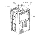
- FIG. 2 is an external perspective view showing the outdoor unit 101 of the air-conditioning apparatus 100 according to Embodiment 1 of the present invention.
- FIG. 3 is a perspective view showing a state where the upper exterior component 1 is removed from the outdoor unit 101 of the air-conditioning apparatus 100 according to Embodiment 1 of the present invention.
- the outdoor unit 101 is composed of a square columnar casing.
- a fan guard 3 is attached to the exhaust port 2 on the upper surface of the outdoor unit 101.
- the outdoor heat exchanger 107 is arranged on the side surface of the housing below the fan 10. The outdoor unit 101 takes in air from the outside of the side surface of the housing, exchanges heat with the outdoor heat exchanger 107, and exhausts the heat-exchanged exhaust air upward by the fan 10.
- a fan 10 is arranged below the exhaust port 2.
- the fan 10 has a boss portion 10a, which is a cylindrical central portion connected to the rotating shaft 12, and a blade portion 10b extending outward in the radial direction from the boss portion 10a.
- the fan 10 blows upward.
- the fan 10 is a resin integrally molded product in which the boss portion 10a and the blade portion 10b are integrated.
- a drive source 11 is arranged below the fan 10.
- the drive source 11 is, for example, a fan motor such as an electric motor.
- the drive source 11 is connected to the fan 10 via a rotary shaft 12 to drive the fan 10 to rotate.
- the drive source 11 is installed on the support base 13 while bridging it.
- the lower surface 10a1 of the boss portion 10a is configured as a shielding portion 20 that covers the upper surface 11a of the drive source 11.
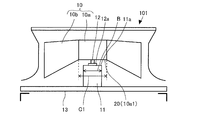
- ⁇ Details of the shielding unit 20> 4 is explanatory drawing which shows the cross section of the fan 10 and the drive source 11 in the outdoor unit 101 of the air conditioning apparatus 100 which concerns on Embodiment 1 of this invention.
- the shielding portion 20 is the lower surface 10a1 of the boss portion 10a whose diameter C1 is larger than the maximum outer diameter dimension B of the upper surface 11a of the drive source 11 in the radial direction.
- the outer side in the radial direction of the lower surface 10a1 of the boss portion 10a, which is the shielding portion 20, is positioned below the boss portion 10a also as the lower surface 10a1 of the boss portion 10a.
- the outside in the radial direction of the lower surface 10a1 of the boss portion 10a and the position below the boss portion 10a which also serves as the lower surface 10a1 of the boss portion 10a are substantially equal in height.
- the outside in the radial direction of the lower surface 10a1 of the boss portion 10a which is the shielding portion 20 has a diameter larger than the upper surface 11a of the drive source 11 in the radial direction by 10 mm or more. That is, the dimension C1 is larger than the maximum outer diameter dimension B by 10 mm in the radial direction.
- the shielding portion 20 is the lower surface 10a1 of the boss portion 10a having a diameter larger than the upper surface 11a of the drive source 11 in the radial direction.
- the lower surface 10a1 of the boss portion 10a prevents the icicles generated on the lower surface 10a1 of the boss portion 10a of the fan 10 from being connected to the upper surface 11a of the drive source 11.
- the lower surface 10a1 on the outer peripheral side of the boss portion 10a of the fan 10 is a flat surface
- the water will pass through the flat lower surface 10a1 to the inside of the boss portion 10a and the icicles will reach the drive source 11. .. Therefore, as will be described later, the lower surface 10a1 of the boss portion 10a of the fan 10 is inclined more downward in the radial direction than in the radial inside with respect to the central axis of the fan 10.
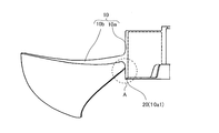
- FIG. 5 is an explanatory diagram showing a left side cross section of the fan 10 in the outdoor unit 101 of the air conditioning apparatus 100 according to Embodiment 1 of the present invention.
- FIG. 6 is an explanatory diagram showing a left side cross section of the boss portion 10a of the fan 10 in the outdoor unit 101 of the air conditioning apparatus 100 according to Embodiment 1 of the present invention in an enlarged manner in a portion A of FIG.
- the lower surface 10a1 of the boss portion 10a formed on the shielding portion 20 has a shape in which the radially outer side is positioned lower than the radially inner side.
- the lower surface 10a1 of the boss portion 10a formed on the shielding portion 20 is formed into a taper surface whose outer side in the radial direction is inclined lower than inner side in the radial direction.
- a curved R portion is required on the lower surface 10a1 of the boss portion 10a for molding.
- such an R portion is not included outside the lower surface 10a1 of the boss portion 10a in the radial direction.
- the R portion necessary for processing is not included on the outer side in the radial direction of the lower surface 10a1 of the boss portion 10a.
- the R portion is included in the outer peripheral surface portion of the boss portion 10a.
- the shape of the lower surface 10a1 is described as inclined.
- the lower surface 10a1 of the boss portion 10a formed on the shielding portion 20 may have a shape in which the radially outer side is positioned lower than the radially inner side.
- the lower surface 10a1 of the boss portion 10a may have a shape in which the inner side has a high step.
- the lowermost portion of the lower surface 10a1 of the boss portion 10a on the inner side in the radial direction needs to be larger than the maximum outer diameter dimension B of the upper surface 11a of the drive source 11 by 20 mm or more.
- the size of the icicle is determined by complex factors such as the amount of flowing water, ambient temperature, outside wind or elapsed time. For this reason, it is not possible to determine the necessary shape or size. However, if it is assumed that the icicles are generated in the range of the inner-outer diameter difference of less than 10 mm in the radial direction, the dimension C1 of the lower surface 10a1 of the boss portion 10a is smaller than the maximum outer-diameter dimension B of the drive source 11 by the radius. If it is preliminarily formed to have a shape of 10 mm or more on the outside in the direction, it is assumed that a startup failure does not occur in many cases.
- the lower surface 10a1 of the boss portion 10a of the fan 10 is formed with an inclination or a step whose height decreases from the inner side in the radial direction of the fan 10 to the outer side in the radial direction.
- the outdoor unit 101 of the air conditioner 100 has the boss portion 10a through which the rotary shaft 12 passes and the blade portion 10b extending outward in the radial direction from the boss portion 10a, and the fan 10 that blows air upwards. Equipped with.
- the outdoor unit 101 of the air conditioner 100 is provided below the fan 10 and includes a drive source 11 that is connected to the fan 10 via a rotation shaft 12 to drive the fan 10 to rotate.
- the outdoor unit 101 of the air conditioner 100 serves as a shielding unit 20 that covers the entire upper surface 11a of the drive source 11 and prevents the icicles generated on the lower surface of the boss portion 10a of the fan 10 from being connected to the upper surface 11a of the drive source 11.
- the lower surface 10a1 of the boss portion 10a is provided.
- the shielding portion 20 covers the entire upper surface 11a of the drive source 11, and even when icy rain falls when the fan 10 is stopped, the icicles generated on the lower surface 10a1 of the boss portion 10a of the fan 10 shield the shielding portion. It is excluded from the upper surface 11a of the drive source 11 via 20 and the boss portion 10a of the fan 10 and the drive source 11 are not integrally connected by ice. Therefore, even if it rains with ice when the fan 10 is stopped, the fan 10 and the drive source 11 are integrally connected by the icicles and are not fixed, and the start failure of the fan 10 does not occur, thus preventing the inoperable situation. it can.
- the outer side in the radial direction of the shield 20 is located below the boss 10a.
- the shielding portion 20 can cover the upper surface 11a of the drive source 11.
- the shielding portion 20 is the lower surface 10a1 of the boss portion 10a having a diameter larger than the upper surface 11a of the drive source 11 in the radial direction.
- the icicles generated on the lower surface 10a1 of the boss portion 10a of the fan 10 extend radially outward from the upper surface 11a of the driving source 11, and the icicles do not stick to the upper surface 11a of the driving source 11. Therefore, the icicles generated on the lower surface 10a1 of the boss portion 10a of the fan 10 are excluded from the upper surface 11a of the drive source 11 via the lower surface 10a1 of the boss portion 10a of the fan 10 that is the shielding portion 20, and the boss portion 10a of the fan 10 is removed. And the drive source 11 are not integrally connected by ice.
- the lower surface 10a1 of the boss portion 10a formed on the shielding portion 20 has a shape in which the radially outer side is located lower than the radially inner side.
- the icicles generated on the lower surface 10a1 of the boss portion 10a of the fan 10 come down to the outer side in the radial direction of the lower surface 10a1 of the boss portion 10a located below the inner side in the radial direction by its own weight. Therefore, the icicles generated on the lower surface 10a1 of the boss portion 10a of the fan 10 are more likely to extend radially outward than the upper surface 11a of the drive source 11, and the icicles are not fixed to the upper surface 11a of the drive source 11.
- the outer side in the radial direction of the shield 20 has a diameter larger than the upper surface 11a of the drive source 11 by 20 mm or more toward the outer side in the radial direction.
- the large-diameter shield portion 20 covers the upper surface 11a of the drive source 11 radially outward of the upper surface 11a of the drive source 11.
- the fan 10 is a resin integrally molded product.
- the fan 10 can be easily manufactured.
- the air conditioning apparatus 100 includes the outdoor unit 101 of the air conditioning apparatus 100 described above.
- the fan 10 and the drive source 11 are integrated by the icicles even if icy rain falls when the fan 10 is stopped. It is possible to prevent a situation in which the fan cannot be operated because the fan 10 is not connected and fixed and the fan 10 does not malfunction.
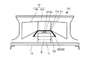
- Embodiment 2. 7 is explanatory drawing which shows the cross section of the fan 10, the drive source 11, and the cover component 30 in the outdoor unit 101 of the air conditioning apparatus 100 which concerns on Embodiment 2 of this invention.
- the description of the same items as those in the above-described embodiment will be omitted, and only the characteristic portions will be described.
- the shielding unit 20 is a cover component 30 provided between the fan 10 and the drive source 11.
- the cover component 30 has a truncated cone shape in which the outer side in the radial direction is located lower than the inner side in the radial direction.
- the cover component 30, which is the shield 20 has a bent portion 31 between the radially inner side and the radially outer side.
- the lowermost portion of the cover part 30 that is the shielding part 20 on the outer side in the radial direction is located below the upper surface 11 a of the drive source 11.
- the radial outside of the cover component 30 that is the shielding portion 20 has a radius of 10 mm or more toward the radial outside of the upper surface 11a of the drive source 11.
- the cover part 30 is a hollow truncated cone shape that is a separate part from the fan 10.
- the cover component 30 is inclined at the outer side in the radial direction below the inner side in the radial direction.
- the dimension C2 of the radially outermost lower portion of the cover component 30 is larger than the maximum outer diameter dimension B of the upper surface 11a of the drive source 11.
- a through hole through which the rotary shaft 12 is inserted is formed.
- the fan 10 and the cover component 30 are integrally attached by means such as fitting, bonding, welding or bolting.
- the cover component 30 rotates integrally with the fan 10. Therefore, for the purpose of reducing the driving power, it is desirable that the same shape is provided in the circumferential direction, which is a cross-sectional shape such that there is no uneven shape in the rotation direction like a truncated cone shape.
- the shape of the cover component 30 is not limited as long as the integrated fan 10 as a whole is balanced against rotation.
- FIG. 8 is explanatory drawing which shows the cross section of the fan 10, the drive source 11, and the cover component 30 in the outdoor unit 101 of the air conditioning apparatus 100 which concerns on the modification 1 of Embodiment 2 of this invention.
- description of the same items as those in the above-described embodiment and the like is omitted, and only the characteristic part will be described.
- the cover component 30 that is the shielding portion 20 has a curved surface portion 32 that bends downward with a bending radius of 10 mm or more outside the bending portion 31 in the radial direction.
- the cover component 30 does not have a truncated cone shape, but is bent and curved on the way from the boss portion 10a to the outside when viewed in cross section.
- the fan 10 has a higher passing wind speed as it goes radially outward from the center. For this reason, if there is an air path obstruction element such as the cover component 30 on the outer side in the radial direction, the power consumption of the drive source 11 is deteriorated. In addition, the closer the obstruction element of the air passage is to the fan 10, the greater the influence of the deterioration of the power consumption of the drive source 11. Since the cover component 30 is bent in the middle and has the curved surface portion 32 on the outer side in the radial direction, the outermost portion of the cover component 30 is separated from the fan 10 downward and is distant. Therefore, the deterioration of the power consumption of the drive source 11 is suppressed to the minimum.
- an air path obstruction element such as the cover component 30 on the outer side in the radial direction
- the curved surface portion 32 of the cover component 30 causes turbulence of the air flow when bent at an acute angle, so it is preferable that the curved surface portion 32 be formed in an R shape having a radius of curvature of 10 mm or more.
- FIG. 9 is explanatory drawing which shows the cross section of the fan 10, the drive source 11, and the cover component 30 in the outdoor unit 101 of the air conditioning apparatus 100 which concerns on the modification 2 of Embodiment 2 of this invention.
- description of the same items as those in the above-described embodiment and the like is omitted, and only the characteristic part will be described.
- the cover part 30 as the shielding part 20 has an annular shape.
- the cover component 30 is made of metal.
- the cover component 30 is a component separate from the fan 10 or the drive source 11.
- the cover part 30 has a so-called donut shape.
- the cover component 30 is arranged between the fan 10 and the drive source 11 without being fixed.
- a through hole through which the rotary shaft 12 is inserted is formed.
- the cover component 30 has a flat shape on the upper surface 11a of the drive source 11. However, the cover component 30 may be flat or inclined downward on the outer side in the radial direction with respect to the upper surface 11a of the drive source 11.
- the outer diameter dimension C3 of the cover component 30 is larger than the maximum outer diameter dimension B of the drive source 11.
- the cover part 30 is not fixed. For this reason, the cover component 30 is made of a metal-worked product so as not to come into contact with the fan 10 by being lifted up by the normal wind pressure, and the weight is increased.
- a through hole having a diameter larger than that of the bearing portion 12a is formed in the central portion of the cover component 30 in order to avoid interference with the bearing portion 12a provided on the rotary shaft 12 at the center of the drive source 11.
- the through hole be formed as small as possible.
- the cover component 30 that is the shielding portion 20 may be provided on the lower surface facing the upper surface 11a of the drive source 11 with a first protruding portion (not shown) protruding downward to reduce the contact area.
- the first protrusion prevents the upper surface 11a of the drive source 11 and the cover component 30 from sticking to each other due to freezing.
- the first protrusion may be provided partially downward on the cover component 30 when the upper surface 11a of the drive source 11 is flat.
- the fact that the upper surface 11a of the drive source 11 is flat means that there is no step or the like caught on the upper surface 11a of the drive source 11 even if the upper surface 11a of the drive source 11 rotates in the presence of the first protrusion.
- FIG. 10 is explanatory drawing which shows the cross section of the fan 10, the drive source 11, and the cover component 30 in the outdoor unit 101 of the air conditioning apparatus 100 which concerns on the modification 3 of Embodiment 2 of this invention.
- description of the same items as those in the above-described embodiment and the like is omitted, and only the characteristic part will be described.
- the cover component 30 has a contact portion 33, a lower end portion 34, an inclined portion 35, and an upper end portion 36.
- the contact portion 33 is in contact with the upper surface 11a of the drive source 11.
- the lower end portion 34 is bent downward from the outer side of the contact portion 33 in the radial direction, and extends downward in the shape of an annular protrusion on the outer side in the radial direction of the outer periphery of the drive source 11.
- the inclined portion 35 is inclined in a tapered shape from the inner side of the contact portion 33 in the radial direction to be spaced apart from the bearing portion 12 a of the drive source 11.
- the upper end portion 36 is bent upward from the inclined portion 35, is spaced apart from the rotary shaft 12, and extends upward in the shape of an annular protrusion.
- the central space of the upper end portion 36 is a through hole through which the rotary shaft 12 is inserted.
- a second protrusion 37 that protrudes toward the center of the drive source 11 is provided on the inner peripheral surface of the cover component 30 that is the shield 20 that faces the outer peripheral surface of the drive source 11 on the radially outer side. ..
- the outer diameter dimension C4 of the cover component 30 is larger than the maximum outer diameter dimension B of the upper surface 11a of the drive source 11.
- An inclined portion 35 and an upper end portion 36 are formed in the central portion of the cover component 30 and are arranged above the bearing portion 12a of the drive source 11, and the cover component 30 and the bearing portion 12a are separated from each other. Since the cover part 30 has a complicated shape, it is formed of a resin molded product. It is premised that the cover part 30 is designed so as not to float in the air volume during normal use.
- the cover component 30 has a shape such that even if the cover component 30 floats due to wind pressure, the upper end portion 36 comes into contact with the rotary shaft 12 protruding upward from the drive source 11 and then returns to the original state by itself. ing.
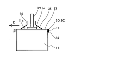
- FIG. 11 is an explanatory diagram showing an enlarged cross section of the drive source 11 and the cover component 30 in the outdoor unit 101 of the air conditioning apparatus 100 according to Modification 3 of Embodiment 2 of the present invention.
- 12 is explanatory drawing which expands and shows the cross section of the drive source 11 in the outdoor unit 101 of the air conditioning apparatus 100 which concerns on the modification 3 of Embodiment 2 of this invention, and the cover component 30 of the most biased state in the horizontal direction.
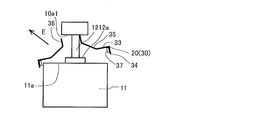
- FIG. 13 shows that the drive source 11 in the outdoor unit 101 of the air conditioner 100 according to the third modification of the second embodiment of the present invention and the upper portion of the inclined cover component 30 are the lower surface 10a1 of the boss portion 10a of the fan 10 and the rotating shaft. It is explanatory drawing which expands and shows the cross section of the cover component 30 in the state of contacting 12.
- the state shown in FIG. 11 is a state in which the cover component 30 is stationary at the normal position.
- the lower end 34 of the cover component 30 is provided with a second protrusion 37 that protrudes inward so as not to move too much in the horizontal direction with respect to the drive source 11.
- the second protrusion 37 is provided above the lowermost portion of the cover component 30 in order to prevent water from flowing around.
- FIG. 12 shows the case where the cover part 30 moves most in the horizontal direction in the direction of arrow D in the drawing. As shown in FIG. 12, even when the cover part 30 is moved in the most horizontal direction, the cover part 30 and the rotary shaft 12 extending upward from the drive source 11 have a positional relationship in which they do not come into contact with each other.
- the state of FIG. 13 is a state in which the cover component 30 is lifted and tilted in the direction of the arrow E in the drawing.
- One side of the upper end portion 36 of the cover component 30 contacts the lower surface 10a1 of the boss portion 10a of the fan 10 and the outer peripheral surface of the rotary shaft 12, and the cover component 30 is inclined.
- the lowermost portion on the opposite side of the contact portion 33 which is line-symmetric with respect to the rotating shaft 12 is located at a position lower than the upper surface 11a of the drive source 11.
- the cover component 30 does not become unstable when it is detached from the drive source 11, and the self-recovery to the correct state of FIG. 11 is possible.
- the cover component 30 is a component separate from the fan 10 and the drive source 11, and even if the cover component 30 is tilted to one side, a part thereof is present on the outer side in the radial direction of the upper surface 11a, so that water drips from the outer side of the drive source 11. Therefore, the fan 10 and the upper surface 11a of the drive source 11 are not fixed to each other by an icicle. As a result, the fan 10 can be started even under freezing conditions, and the reliability of the outdoor unit 101 is improved.
- cover component 30 is a component separate from the fan 10 and the drive source 11, when the cover component 30 is fixed to the fan 10, the cover component 30 is separated from the fan 10 after the drive source 11 is activated. Rotate simultaneously at the same time. However, thereafter, the cover component 30 is separated from the fan 10 by the external force or the melting of ice, and the cover component 30 returns to the original position on the drive source 11.
- the shielding portion 20 has the bent portion 31 between the radially inner side and the radially outer side.
- the icicles generated on the lower surface 10a1 of the boss portion 10a of the fan 10 are likely to drop radially outward from the bent portion 31 of the shielding portion 20. Therefore, the icicles generated on the lower surface 10a1 of the boss portion 10a of the fan 10 drop radially outward from the shielding portion 20 and are excluded from the upper surface 11a of the drive source 11, so that the boss portion 10a of the fan 10 and the drive source 11 are separated from each other.
- the ice doesn't connect together.
- the shielding portion 20 has the curved surface portion 32 having a bending radius of 10 mm or more on the outer side in the radial direction from the bending portion 31.
- the icicles generated on the lower surface 10a1 of the boss portion 10a of the fan 10 are more likely to drop from the bent portion 31 of the shielding portion 20 at the curved surface portion 32 radially outside. Therefore, the icicles generated on the lower surface 10a1 of the boss portion 10a of the fan 10 drop radially outward from the shielding portion 20 and are excluded from the upper surface 11a of the drive source 11, so that the boss portion 10a of the fan 10 and the drive source 11 are separated from each other.
- the ice doesn't connect together.
- a first protrusion protruding downward is provided on the lower surface of the shield 20 facing the upper surface 11a of the drive source 11.
- the first protrusion reduces the contact area between the shield 20 and the upper surface 11a of the drive source 11. Therefore, it is difficult for the shield 20 and the upper surface 11a of the drive source 11 to freeze together.
- the inner peripheral surface of the shield 20 facing the outer peripheral surface of the drive source 11 on the outer side in the radial direction is provided with the second protrusion 37 protruding toward the center of the drive source 11. Has been.
- the second protrusion 37 makes it difficult for the shield 20 to contact the rotating shaft 12. As a result, it is possible to prevent the shielding part 20 from coming into contact with the rotating shaft 12 and preventing the noise when the shielding part 20 comes into contact with the rotating shaft 12 or the adverse effects such as the following rotation.
- the lowermost portion on the outer side in the radial direction of the shield 20 is located below the upper surface 11a of the drive source 11.
- the icicles generated on the lower surface 10a1 of the boss portion 10a of the fan 10 fall off the upper surface 11a of the drive source 11 from the lowermost portion on the outer side in the radial direction of the shielding portion 20.
- the lowermost portion on the opposite contact side when the inner peripheral surface of the through hole inserted into the rotary shaft 12 in the shield portion 20 is in contact with the rotary shaft 12 is the upper surface of the drive source 11. It is located below 11a.
- the lowermost portion of the shield portion 20 on the opposite contact side is caught by the drive source 11, and the shield portion 20 can stably maintain the state of covering the upper surface 11a of the drive source 11.
- the shielding unit 20 is the cover component 30 provided between the fan 10 and the drive source 11.
- the icicles generated on the lower surface 10a1 of the boss portion 10a of the fan 10 are received by the cover component 30 that is the shielding portion 20 and are excluded from the upper surface 11a of the drive source 11, and the boss portion 10a of the fan 10 and the drive portion are driven.
- the source 11 is not integrally connected with ice.
- the cover component 30, which is a separate component connected to the boss portion 10a of the fan 10, rotates integrally with the fan 10 until the icicles melt.
- the cover component 30 has a truncated cone shape in which the radially outer side is located lower than the radially inner side.
- the icicles generated on the lower surface 10a1 of the boss portion 10a of the fan 10 easily fall on the cover component 30, which is the shielding portion 20, radially outward.
- the cover component 30 has an annular shape.
- the icicles generated on the lower surface 10a1 of the boss portion 10a of the fan 10 are received by the cover component 30 that is the shielding portion 20 and are excluded from the upper surface 11a of the drive source 11, and the boss portion 10a of the fan 10 and the drive portion are driven.
- the source 11 is not integrally connected with ice.
- the cover component 30, which is a separate component connected to the boss portion 10a of the fan 10, rotates integrally with the fan 10 until the icicles melt.
- the cover component 30 includes the contact portion 33 that contacts the upper surface 11a of the drive source 11, and the contact portion 33 that bends downward from the radial outer side of the contact portion 33 and is radially outer than the outer periphery of the drive source 11.
- a slant portion 35 that is slanted upward from the inner side of the contact portion 33 in the radial direction and separated from the bearing portion 12a of the drive source 11, and is slanted upward from the slant portion 35.
- an upper end portion 36 that is spaced apart and extends upward.
- the icicles generated on the lower surface 10a1 of the boss portion 10a of the fan 10 easily fall on the cover component 30, which is the shielding portion 20, radially outward.
- the cover component 30 is made of metal.
- the weight of the cover component 30 is increased, and the cover component 30 does not float and does not come into contact with the fan 10 due to the normal wind pressure generated by the fan 10.
- the first and second embodiments of the present invention may be combined or applied to other parts.
Landscapes
- Engineering & Computer Science (AREA)
- Chemical & Material Sciences (AREA)
- Combustion & Propulsion (AREA)
- Mechanical Engineering (AREA)
- General Engineering & Computer Science (AREA)
- Other Air-Conditioning Systems (AREA)
Abstract
空気調和装置の室外機は、回転軸が通るボス部及び当該ボス部から半径方向外側に伸びる羽根部を有し、上方に送風するファンと、ファンの下方に配置され、ファンと回転軸を介して繋がってファンを回転駆動する駆動源と、駆動源の上面の全体を覆い、ファンのボス部の下面に発生した氷柱の駆動源の上面への連結を回避する遮蔽部と、を備える。
Description
本発明は、上部に配置されて上方に送風するファンと、ファンの下方に配置されてファンと回転軸を介して繋がってファンを回転駆動する駆動源とを備える空気調和装置の室外機及び空気調和装置に関する。
ビルあるいは商業施設などに設置される空気調和装置の室外機では、集中設置された場合の排気性能を考慮し、筐体から上向きに排気される場合がある。このような場合に、室外機には、最上面に安全面を考慮したファンガードが配置されている。ファンガードの下方には、ファン及び駆動源であるファンモータが設置されている。
このとき、空力特性又は構造を考慮すると、ファンモータがファンの下方に設置される。つまり、室外機は、上部に配置されて上方に送風するファンと、ファンの下方に配置されてファンと回転軸を介して繋がってファンを回転駆動するファンモータとを備える。
このような室外機では、熱交換器がファンの下方における筐体の側面に配置される。室外機は、筐体の側面の外部から吸気して熱交換器によって熱交換し、熱交換後の排気をファンによって上方に送風して排気する方式が一般的である。
室外機は、屋外に設置される。このため、ファンの停止時に、雨がファンガードを通して筐体の内部に滴下する。雪は、ファンガード上、ファン上又は筐体内に堆積する。室外機が雨にさらされても室外機の運転上の問題が無い。しかし、ファンガード上又はファン上に積もった雪は、通風又はファンの動作を阻害する。そのため、雪が多い地域では、筐体の上部に防雪フードと一般的に呼ばれる雪避けが設置される場合がある(たとえば、特許文献1参照)。
一方、豪雪地帯でない場合又はコストの関係上、防雪フードが付いていない場合もある。そのような室外機では、外気温度などから降雪又は降雪の可能性の判断を行うことにより、室外機の停止時でもファンのみが強制的に回転駆動され、除雪する制御が導入されている場合もある(たとえば、特許文献2参照)。しかし、雪が降っていない状態で外気温度が低い場合があるため、ファンモータの駆動動力が無駄になり、ファン駆動音も発生する。
特許文献1に記載の防雪フードが付いていない室外機かつ特許文献2に記載の技術を搭載していない室外機では、ファンの停止時に氷雨が降ってきた場合に、雨が氷となり、氷柱ができ易くなる。ファンのボス部の下面に発生した氷柱は、その直下にあるファンモータと氷で一体的に繋がる場合がある。このような場合には、ファンの起動トルクよりも強固に氷が固着すると、ファンの起動不良が発生し、空気調和装置の運転ができない課題がある。
本発明は、上記課題を解決するためのものであり、ファンの停止時に氷雨が降ってきた場合でも、ファンと駆動源とが氷柱によって一体的に繋がって固着せず、ファンの起動不良が発生せず、運転不能の事態が防止できる空気調和装置の室外機及び空気調和装置を提供することを目的とする。
本発明に係る空気調和装置の室外機は、回転軸が通るボス部及び当該ボス部から半径方向外側に伸びる羽根部を有し、上方に送風するファンと、前記ファンの下方に配置され、前記ファンと前記回転軸を介して繋がって前記ファンを回転駆動する駆動源と、前記駆動源の上面の全体を覆い、前記ファンの前記ボス部の下面に発生した氷柱の前記駆動源の上面への連結を回避する遮蔽部と、を備えるものである。
本発明に係る空気調和装置は、上記の空気調和装置の室外機を備えるものである。
本発明に係る空気調和装置の室外機及び空気調和装置によれば、駆動源の上面の全体を覆い、ファンのボス部の下面に発生した氷柱の駆動源の上面への連結を回避する遮蔽部を備える。このため、遮蔽部が駆動源の上面の全体を覆い、ファンの停止時に氷雨が降ってきた場合には、ファンのボス部の下面に発生した氷柱が遮蔽部を介して駆動源の上面から除外され、ファンのボス部と駆動源とが氷で一体的に繋がらない。したがって、ファンの停止時に氷雨が降ってきた場合でも、ファンと駆動源とが氷柱によって一体的に繋がって固着せず、ファンの起動不良が発生せず、運転不能の事態が防止できる。
以下、図面に基づいて本発明の実施の形態について説明する。なお、各図において、同一の符号を付したものは、同一の又はこれに相当するものであり、これは明細書の全文において共通している。また、断面図の図面においては、視認性に鑑みて適宜ハッチングを省略している。さらに、明細書全文に示す構成要素の形態は、あくまで例示であってこれらの記載に限定されるものではない。
実施の形態1.
<空気調和装置100の構成>
図1は、本発明の実施の形態1に係る空気調和装置100を示す冷媒回路図である。図1に示す空気調和装置100は、室外機101と室内機102とをガス冷媒配管103及び液冷媒配管104によって接続されている。
<空気調和装置100の構成>
図1は、本発明の実施の形態1に係る空気調和装置100を示す冷媒回路図である。図1に示す空気調和装置100は、室外機101と室内機102とをガス冷媒配管103及び液冷媒配管104によって接続されている。
室外機101は、圧縮機105、四方弁106及び室外熱交換器107を有する。
圧縮機105は、吸入した冷媒を圧縮して吐出する。圧縮機105から吐出された冷媒の温度を吐出温度とする。また、圧縮機105の吐出配管の表面温度を吐出温度としてもよい。圧縮機105は、たとえばインバータ回路などにより、運転周波数を任意に変化させ、圧縮機105の単位時間あたりの冷媒を送り出す容量を変化させても良い。
四方弁106は、たとえば冷房運転時と暖房運転時とによって冷媒の流れを切り換える弁である。
室外熱交換器107は、冷媒と室外の空気との熱交換を行う。室外熱交換器107は、冷房運転時に凝縮器として機能し、冷媒を凝縮して液化させる。室外熱交換器107は、暖房運転時に蒸発器として機能し、冷媒を蒸発させ、気化させる。
室内機102は、膨張弁108及び室内熱交換器109を有する。
膨張弁108は、流量制御弁であり、冷媒を減圧して膨張させる。膨張弁108は、たとえば電子式膨張弁などで構成された場合には、図示しない制御装置などの指示に基づいて開度調整を行える。
室内熱交換器109は、たとえば空調対象の空気と冷媒との熱交換を行う。室内熱交換器109は、冷房運転時に蒸発器として機能し、冷媒を蒸発させ、気化させる。室内熱交換器109は、暖房運転時に凝縮器として機能し、冷媒を凝縮して液化させる。
以上のように空気調和装置100を構成することにより、室外機101の四方弁106によって冷媒の流れを切り換え、冷房運転又は暖房運転が実現できる。
<室外機101の構成>
図2は、本発明の実施の形態1に係る空気調和装置100の室外機101を示す外観斜視図である。図3は、本発明の実施の形態1に係る空気調和装置100の室外機101において上部外装部品1を取り外した状態を示す斜視図である。
図2は、本発明の実施の形態1に係る空気調和装置100の室外機101を示す外観斜視図である。図3は、本発明の実施の形態1に係る空気調和装置100の室外機101において上部外装部品1を取り外した状態を示す斜視図である。
図2に示すように、室外機101は、四角柱状の筐体で構成されている。室外機101の上面には、排気口2にファンガード3が取り付けられている。室外熱交換器107がファン10の下方における筐体の側面に配置されている。室外機101は、筐体の側面の外部から吸気して室外熱交換器107によって熱交換し、熱交換後の排気をファン10によって上方に送風して排気する。
上部外装部品1を外した図3に示すように、排気口2の下方には、ファン10が配置されている。ファン10は、回転軸12に繋がれた円筒状の中心部であるボス部10a及び当該ボス部10aから半径方向外側に伸びる羽根部10bを有する。ファン10は、上方に送風する。ファン10は、ボス部10a及び羽根部10bが一体化された樹脂製の一体成形品である。
ファン10の下方には、駆動源11が配置されている。駆動源11は、たとえば電動機などのファンモータである。駆動源11は、ファン10と回転軸12を介して繋がってファン10を回転駆動する。駆動源11は、支持台13上に橋渡しされて設置されている。後述するように、ボス部10aの下面10a1は、駆動源11の上面11aを覆う遮蔽部20に構成されている。
<遮蔽部20の詳細>
図4は、本発明の実施の形態1に係る空気調和装置100の室外機101におけるファン10及び駆動源11の断面を示す説明図である。図4に示すように、遮蔽部20は、駆動源11の上面11aの最大外径寸法Bよりも半径方向外側まで寸法C1が大径であるボス部10aの下面10a1である。
図4は、本発明の実施の形態1に係る空気調和装置100の室外機101におけるファン10及び駆動源11の断面を示す説明図である。図4に示すように、遮蔽部20は、駆動源11の上面11aの最大外径寸法Bよりも半径方向外側まで寸法C1が大径であるボス部10aの下面10a1である。
遮蔽部20であるボス部10aの下面10a1の半径方向外側は、ボス部10aの下面10a1を兼ねてボス部10aの下方に位置する。ここでは、ボス部10aの下面10a1の半径方向外側と、ボス部10aの下面10a1を兼ねたボス部10aの下方の位置とがほぼ等しい高さである。
遮蔽部20であるボス部10aの下面10a1の半径方向外側は、駆動源11の上面11aよりも半径方向外側に向けて10mm以上大径である。すなわち、寸法C1が最大外径寸法Bよりも半径方向に均等に10mmずつそれぞれ大径である。
図4に示すように、遮蔽部20は、駆動源11の上面11aよりも半径方向外側まで大径であるボス部10aの下面10a1である。これにより、通常であれば、ファン10のボス部10aから氷柱が真っ直ぐ降下しても駆動源11の上面11aに真っ直ぐ降下してボス部10a及び駆動源11の上面11aが接続されることはない。つまり、ボス部10aの下面10a1によって、ファン10のボス部10aの下面10a1に発生した氷柱の駆動源11の上面11aへの連結が回避される。しかし、ファン10のボス部10aの外周側の下面10a1が平面である場合には、水が平面な下面10a1を通ってボス部10aの内側に回り込み、氷柱が駆動源11に到達する懸念がある。そこで、後述のように、ファン10のボス部10aの下面10a1は、ファン10の中心軸に対して半径方向内側よりも半径方向外側を下方に傾斜させている。
図5は、本発明の実施の形態1に係る空気調和装置100の室外機101におけるファン10の左側断面を示す説明図である。図6は、本発明の実施の形態1に係る空気調和装置100の室外機101におけるファン10のボス部10aの左側断面を図5のA部にて拡大して示す説明図である。図5及び図6に示すように、遮蔽部20に形成されたボス部10aの下面10a1は、半径方向外側を半径方向内側よりも下方に位置させた形状である。具体的には、遮蔽部20に形成されたボス部10aの下面10a1は、半径方向外側を半径方向内側よりも下方に傾斜させたテーパ面に形成されている。
なお、たとえば樹脂成型のファン10の場合には、成型のためにボス部10aの下面10a1に曲面状のR部が必要となる。しかし、そのようなR部は、ボス部10aの下面10a1の半径方向外側には含まない。その他の成形であっても、加工上必要なR部は、ボス部10aの下面10a1の半径方向外側には含まない。R部は、ボス部10aの外周面部に含まれる。
また、上記にて、下面10a1の形状を傾斜と記載している。しかし、遮蔽部20に形成されたボス部10aの下面10a1は、半径方向外側を半径方向内側よりも下方に位置させた形状であれば良い。たとえば、ボス部10aの下面10a1には、内側が上方に高い段差がある形状でも良い。ただし、この場合には、ボス部10aの下面10a1の段差よりも半径方向内側の最下部は、駆動源11の上面11aの最大外径寸法Bよりも20mm以上大径である必要がある。
氷柱のサイズは、流れる水量、周囲温度、外風又は経過時間などの複雑な要因によって決まる。このため、一概に必要な形状又は寸法は決められない。ただし、氷柱が半径方向にて10mm未満の内外径差の範囲で発生することを想定すれば、ボス部10aの下面10a1の寸法C1は、駆動源11の最大外径寸法Bに対して、半径方向外側に10mm以上の形状に予め形成しておけば多くの場合で起動不良が起きないと想定される。
<遮蔽部20の作用>
ファン10のボス部10aの下面10a1には、ファン10の半径方向内側から半径方向外側に向かって高さの低くなる傾斜又は段差が形成されている。これにより、ファン10のボス部10aの下面10a1において水がボス部10aの下面10a1の内側への回り込みが防止でき、ファン10と駆動源11の上面11aとが氷柱で連結して固定されない。その結果、氷結条件でもファン10が起動できるため、室外機101の信頼性が向上する。
ファン10のボス部10aの下面10a1には、ファン10の半径方向内側から半径方向外側に向かって高さの低くなる傾斜又は段差が形成されている。これにより、ファン10のボス部10aの下面10a1において水がボス部10aの下面10a1の内側への回り込みが防止でき、ファン10と駆動源11の上面11aとが氷柱で連結して固定されない。その結果、氷結条件でもファン10が起動できるため、室外機101の信頼性が向上する。
<実施の形態1の効果>
実施の形態1によれば、空気調和装置100の室外機101は、回転軸12が通るボス部10a及び当該ボス部10aから半径方向外側に伸びる羽根部10bを有し、上方に送風するファン10を備える。空気調和装置100の室外機101は、ファン10の下方に配置され、ファン10と回転軸12を介して繋がってファン10を回転駆動する駆動源11を備える。空気調和装置100の室外機101は、駆動源11の上面11aの全体を覆い、ファン10のボス部10aの下面に発生した氷柱の駆動源11の上面11aへの連結を回避する遮蔽部20としてのボス部10aの下面10a1を備える。
実施の形態1によれば、空気調和装置100の室外機101は、回転軸12が通るボス部10a及び当該ボス部10aから半径方向外側に伸びる羽根部10bを有し、上方に送風するファン10を備える。空気調和装置100の室外機101は、ファン10の下方に配置され、ファン10と回転軸12を介して繋がってファン10を回転駆動する駆動源11を備える。空気調和装置100の室外機101は、駆動源11の上面11aの全体を覆い、ファン10のボス部10aの下面に発生した氷柱の駆動源11の上面11aへの連結を回避する遮蔽部20としてのボス部10aの下面10a1を備える。
この構成によれば、遮蔽部20が駆動源11の上面11aの全体を覆い、ファン10の停止時に氷雨が降ってきた場合でも、ファン10のボス部10aの下面10a1に発生した氷柱が遮蔽部20を介して駆動源11の上面11aから除外され、ファン10のボス部10aと駆動源11とが氷で一体的に繋がらない。したがって、ファン10の停止時に氷雨が降ってきた場合でも、ファン10と駆動源11とが氷柱によって一体的に繋がって固着せず、ファン10の起動不良が発生せず、運転不能の事態が防止できる。
実施の形態1によれば、遮蔽部20の半径方向外側は、ボス部10aの下方に位置している。
この構成によれば、遮蔽部20が駆動源11の上面11aを覆わせられる。
実施の形態1によれば、遮蔽部20は、駆動源11の上面11aよりも半径方向外側まで大径であるボス部10aの下面10a1である。
この構成によれば、ファン10のボス部10aの下面10a1に発生した氷柱が駆動源11の上面11aよりも半径方向外側に伸び、この氷柱が駆動源11の上面11aに固着しない。このため、ファン10のボス部10aの下面10a1に発生した氷柱が遮蔽部20であるファン10のボス部10aの下面10a1を介して駆動源11の上面11aから除外され、ファン10のボス部10aと駆動源11とが氷で一体的に繋がらない。
実施の形態1によれば、遮蔽部20に形成されたボス部10aの下面10a1は、半径方向外側を半径方向内側よりも下方に位置させた形状である。
この構成によれば、ファン10のボス部10aの下面10a1に発生した氷柱が自重によって半径方向内側よりも下方に位置させたボス部10aの下面10a1の半径方向外側に下りて来る。このため、ファン10のボス部10aの下面10a1に発生した氷柱が駆動源11の上面11aよりも半径方向外側に伸び易く、この氷柱が駆動源11の上面11aに固着しない。
実施の形態1によれば、遮蔽部20の半径方向外側は、駆動源11の上面11aよりも半径方向外側に向けて20mm以上大径である。
この構成によれば、駆動源11の上面11aよりも半径方向外側に大径な遮蔽部20が駆動源11の上面11aを覆わせられる。
実施の形態1によれば、ファン10は、樹脂製の一体成形品である。
この構成によれば、ファン10が容易に製造できる。
実施の形態1によれば、空気調和装置100は、上記の空気調和装置100の室外機101を備える。
この構成によれば、空気調和装置100に搭載された空気調和装置100の室外機101では、ファン10の停止時に氷雨が降ってきた場合でも、ファン10と駆動源11とが氷柱によって一体的に繋がって固着せず、ファン10の起動不良が発生せず、運転不能の事態が防止できる。
実施の形態2.
図7は、本発明の実施の形態2に係る空気調和装置100の室外機101におけるファン10、駆動源11及びカバー部品30の断面を示す説明図である。ここでは、上記実施の形態と同事項の説明を省略し、その特徴部分のみを説明する。
図7は、本発明の実施の形態2に係る空気調和装置100の室外機101におけるファン10、駆動源11及びカバー部品30の断面を示す説明図である。ここでは、上記実施の形態と同事項の説明を省略し、その特徴部分のみを説明する。
<遮蔽部20の詳細>
図7に示すように、遮蔽部20は、ファン10と駆動源11との間に設けられたカバー部品30である。カバー部品30は、半径方向外側を半径方向内側よりも下方に位置させた円錐台形状である。遮蔽部20であるカバー部品30は、半径方向内側と半径方向外側との間に屈曲部31を有する。遮蔽部20であるカバー部品30の半径方向外側の最下部は、駆動源11の上面11aよりも下方に位置する。遮蔽部20であるカバー部品30の半径方向外側は、半径において、駆動源11の上面11aよりも半径方向外側に向けて10mm以上大径である。
図7に示すように、遮蔽部20は、ファン10と駆動源11との間に設けられたカバー部品30である。カバー部品30は、半径方向外側を半径方向内側よりも下方に位置させた円錐台形状である。遮蔽部20であるカバー部品30は、半径方向内側と半径方向外側との間に屈曲部31を有する。遮蔽部20であるカバー部品30の半径方向外側の最下部は、駆動源11の上面11aよりも下方に位置する。遮蔽部20であるカバー部品30の半径方向外側は、半径において、駆動源11の上面11aよりも半径方向外側に向けて10mm以上大径である。
カバー部品30は、ファン10とは別部品の中空の円錐台形状である。カバー部品30は、半径方向外側を半径方向内側よりも下方に傾斜させている。カバー部品30の半径方向外側の最下部の寸法C2は、駆動源11の上面11aの最大外径寸法Bよりも大径である。カバー部品30の中心には、回転軸12を挿通した貫通孔が形成されている。
ファン10とカバー部品30とは、嵌め込み、接着、溶接又はボルト止めなどの手段によって一体的に取り付けられている。カバー部品30は、ファン10と一体的に回転する。このため、駆動電力の削減を目的として、円錐台形状のように回転方向に凹凸形状が無いような断面形状である周方向に同一形状が望ましい。しかし、カバー部品30の形状は、一体化されたファン10全体として回転に対するバランスが取れていればその限りではない。
<変形例1>
図8は、本発明の実施の形態2の変形例1に係る空気調和装置100の室外機101におけるファン10、駆動源11及びカバー部品30の断面を示す説明図である。ここでは、上記実施の形態などと同事項の説明を省略し、その特徴部分のみを説明する。
図8は、本発明の実施の形態2の変形例1に係る空気調和装置100の室外機101におけるファン10、駆動源11及びカバー部品30の断面を示す説明図である。ここでは、上記実施の形態などと同事項の説明を省略し、その特徴部分のみを説明する。
<遮蔽部20の詳細>
図8に示すように、遮蔽部20であるカバー部品30は、屈曲部31よりも半径方向外側に曲げ半径10mm以上の下方に曲がる曲面部32を有する。カバー部品30は、円錐台形状ではなく、断面でみた場合にボス部10aから外側に向かう途中で折れ曲がって湾曲している。
図8に示すように、遮蔽部20であるカバー部品30は、屈曲部31よりも半径方向外側に曲げ半径10mm以上の下方に曲がる曲面部32を有する。カバー部品30は、円錐台形状ではなく、断面でみた場合にボス部10aから外側に向かう途中で折れ曲がって湾曲している。
ファン10は、中心から半径方向外側に向かうにつれて、通過風速が大きくなる。このため、半径方向外側にカバー部品30のような風路の妨害要素があると、駆動源11の消費電力の悪化が招かれる。また、風路の妨害要素がファン10の近くあるほど、駆動源11の消費電力の悪化の影響が大きくなる。カバー部品30が途中で屈曲されて半径方向外側に曲面部32を有することにより、カバー部品30の最外部がファン10から下方に離間して遠くなる。このため、駆動源11の消費電力の悪化が最小限に抑えられる。
カバー部品30の曲面部32は、鋭角に曲げられると、気流の乱れを発生させるため、半径10mm以上の曲率半径であるR形状に形成されると良い。
<変形例2>
図9は、本発明の実施の形態2の変形例2に係る空気調和装置100の室外機101におけるファン10、駆動源11及びカバー部品30の断面を示す説明図である。ここでは、上記実施の形態などと同事項の説明を省略し、その特徴部分のみを説明する。
図9は、本発明の実施の形態2の変形例2に係る空気調和装置100の室外機101におけるファン10、駆動源11及びカバー部品30の断面を示す説明図である。ここでは、上記実施の形態などと同事項の説明を省略し、その特徴部分のみを説明する。
図9に示すように、遮蔽部20としてのカバー部品30は、円環形状である。カバー部品30は、金属製である。
カバー部品30は、ファン10又は駆動源11とは別部品である。カバー部品30は、いわゆるドーナツ形状である。カバー部品30は、ファン10と駆動源11との間に固定せずに配置されている。カバー部品30の中心には、回転軸12を挿通した貫通孔が形成されている。
なお、カバー部品30は、駆動源11の上面11aにて平らな形状である。しかし、カバー部品30は、駆動源11の上面11aよりも半径方向外側にて平ら又は下方に傾斜しても良い。
カバー部品30の外径の寸法C3は、駆動源11の最大外径寸法Bよりも大径である。カバー部品30は、固定されていない。このため、カバー部品30は、通常の風圧で浮いてしまってファン10と接触しないように金属加工品で構成されて重量が増加されている。
カバー部品30の中央部には、駆動源11の中心の回転軸12に設けられた軸受部12aとの干渉を回避する目的で軸受部12aよりも大径な貫通孔を形成している。しかし、この貫通孔は、室外機101の運転中のガタツキを防止するため、できるだけ小さ目に形成する方が良い。
なお、遮蔽部20であるカバー部品30における駆動源11の上面11aに対向する下面には、接触面積を減らす下方に突出した図示しない第1突起部が設けられても良い。第1突起部は、駆動源11の上面11aとカバー部品30とが凍結で固着することを防止する。第1突起部は、駆動源11の上面11aが平らである場合にカバー部品30に部分的に下向きに設けられると良い。ここで、駆動源11の上面11aが平らという意味は、第1突起部の存在する状態で回転しても駆動源11の上面11aに引っ掛かる段差などが無いことを意味する。
<変形例3>
図10は、本発明の実施の形態2の変形例3に係る空気調和装置100の室外機101におけるファン10、駆動源11及びカバー部品30の断面を示す説明図である。ここでは、上記実施の形態などと同事項の説明を省略し、その特徴部分のみを説明する。
図10は、本発明の実施の形態2の変形例3に係る空気調和装置100の室外機101におけるファン10、駆動源11及びカバー部品30の断面を示す説明図である。ここでは、上記実施の形態などと同事項の説明を省略し、その特徴部分のみを説明する。
図10に示すように、カバー部品30は、接触部33と、下端部34と、傾斜部35と、上端部36とを有する。接触部33は、駆動源11の上面11aに接触している。下端部34は、接触部33の半径方向外側から下方に屈曲して駆動源11の外周よりも半径方向外側にて円環突起形状で下方に延びている。傾斜部35は、接触部33の半径方向内側から上方にテーパ形状に傾斜して駆動源11の軸受部12aと離間している。上端部36は、傾斜部35から上方に屈曲して回転軸12と離間して円環突起形状で上方に延びている。上端部36の中心空間は、回転軸12を挿通する貫通孔となっている。
遮蔽部20であるカバー部品30における半径方向外側での駆動源11の外周面に対向する内周面には、駆動源11の中心方向に向かって突出した第2突起部37が設けられている。
カバー部品30の外径の寸法C4は、駆動源11の上面11aの最大外径寸法Bよりも大径である。カバー部品30の中央部には、傾斜部35及び上端部36が形成され、駆動源11の軸受部12aよりも上方に配置され、カバー部品30と軸受部12aとが離間している。カバー部品30は、形状が複雑であるので、樹脂成型品で形成されている。カバー部品30は、通常の使用時の風量で浮かないように設計されることが前提である。しかし、カバー部品30は、カバー部品30が仮に風圧で浮いた場合でも、駆動源11から上方に突出する回転軸12に上端部36が接触した後に元の状態に自己復帰するような形状になっている。
図11は、本発明の実施の形態2の変形例3に係る空気調和装置100の室外機101における駆動源11及びカバー部品30の断面を拡大して示す説明図である。図12は、本発明の実施の形態2の変形例3に係る空気調和装置100の室外機101における駆動源11及び水平方向で最も偏った状態のカバー部品30の断面を拡大して示す説明図である。図13は、本発明の実施の形態2の変形例3に係る空気調和装置100の室外機101における駆動源11及び傾いたカバー部品30の上部がファン10のボス部10aの下面10a1及び回転軸12に接触した状態のカバー部品30の断面を拡大して示す説明図である。
遮蔽部20であるカバー部品30における回転軸12に挿通された上端部36の貫通孔の内周面を回転軸12に接触させた状態のときの反接触側の最下部は、駆動源11の上面11aよりも下方に位置している。具体的には、図11、図12及び図13を用いて以下に説明する。
図11の状態は、カバー部品30が通常の位置に静止した状態である。カバー部品30の下端部34には、駆動源11に対して水平方向に移動し過ぎないように、内側に突出した第2突起部37が設けられている。第2突起部37は、水の回り込みを防ぐため、カバー部品30の最下部よりも上方に設けられている。
図12の状態は、カバー部品30が図示矢印D方向に水平方向に最も移動した場合を示したものである。図12に示すように最も水平方向に移動した場合でも、カバー部品30と駆動源11から上方に伸びる回転軸12とは、接触しない位置関係となる。
図13の状態は、カバー部品30が図示矢印E方向に浮き上がって傾いた状態である。カバー部品30の上端部36の片側がファン10のボス部10aの下面10a1と回転軸12の外周面とに接触し、カバー部品30が傾いている。図13の状態でも、カバー部品30は、接触部33に対して回転軸12を中心とした線対称の反対側の最下部が駆動源11の上面11aよりも低い位置に存在する。これにより、カバー部品30が駆動源11に対して外れた状態で不安定化することがなく、正しい図11の状態に自己復帰できる。
<遮蔽部20の作用>
カバー部品30がファン10及び駆動源11とは別体の部品であって、一方に傾いた状態でも一部が上面11aの半径方向外側に存在することにより、水が駆動源11の外側から滴下するため、ファン10と駆動源11の上面11aとが氷柱で一定的に固定されない。その結果、氷結条件でも、ファン10が起動でき、室外機101の信頼性が向上する。
カバー部品30がファン10及び駆動源11とは別体の部品であって、一方に傾いた状態でも一部が上面11aの半径方向外側に存在することにより、水が駆動源11の外側から滴下するため、ファン10と駆動源11の上面11aとが氷柱で一定的に固定されない。その結果、氷結条件でも、ファン10が起動でき、室外機101の信頼性が向上する。
また、カバー部品30がファン10及び駆動源11とは別体の部品であることにより、カバー部品30がファン10と固着した場合には、駆動源11の起動後ではカバー部品30がファン10と一体的に同時に回転する。しかしその後、外力又は氷の融解によって、カバー部品30がファン10と分離され、カバー部品30が駆動源11上の元の位置に戻って来る。
<実施の形態2の効果>
実施の形態2によれば、遮蔽部20は、半径方向内側と半径方向外側との間に屈曲部31を有する。
実施の形態2によれば、遮蔽部20は、半径方向内側と半径方向外側との間に屈曲部31を有する。
この構成によれば、ファン10のボス部10aの下面10a1に発生した氷柱が遮蔽部20の屈曲部31から半径方向外側に降下し易くなる。このため、ファン10のボス部10aの下面10a1に発生した氷柱が遮蔽部20から半径方向外側に降下して駆動源11の上面11aから除外され、ファン10のボス部10aと駆動源11とが氷で一体的に繋がらない。
実施の形態2によれば、遮蔽部20は、屈曲部31よりも半径方向外側に曲げ半径10mm以上の曲面部32を有する。
この構成によれば、ファン10のボス部10aの下面10a1に発生した氷柱が遮蔽部20の屈曲部31から半径方向外側の曲面部32にてより降下し易くなる。このため、ファン10のボス部10aの下面10a1に発生した氷柱が遮蔽部20から半径方向外側に降下して駆動源11の上面11aから除外され、ファン10のボス部10aと駆動源11とが氷で一体的に繋がらない。
実施の形態2によれば、遮蔽部20における駆動源11の上面11aに対向する下面には、下方に突出した第1突起部が設けられている。
この構成によれば、第1突起部が遮蔽部20と駆動源11の上面11aとの間の接触面積を削減する。このため、遮蔽部20と駆動源11の上面11aとが一緒に凍結し難くなる。
実施の形態2によれば、遮蔽部20における半径方向外側での駆動源11の外周面に対向する内周面には、駆動源11の中心方向に向かって突出した第2突起部37が設けられている。
この構成によれば、第2突起部37が遮蔽部20を回転軸12に接触し難くする。これにより、遮蔽部20が回転軸12に接触せず、遮蔽部20が回転軸12に接触した際の騒音又は従動しての回転などの弊害が防止できる。
実施の形態2によれば、遮蔽部20の半径方向外側の最下部は、駆動源11の上面11aよりも下方に位置している。
この構成によれば、ファン10のボス部10aの下面10a1に発生した氷柱が遮蔽部20の半径方向外側の最下部から駆動源11の上面11aを外れて降下する。
実施の形態2によれば、遮蔽部20における回転軸12に挿通された貫通孔の内周面を回転軸12に接触させた状態のときの反接触側の最下部は、駆動源11の上面11aよりも下方に位置している。
この構成によれば、遮蔽部20の反接触側の最下部が駆動源11に引っ掛かり、遮蔽部20が駆動源11の上面11aを覆う状態を安定的に維持できる。
実施の形態2によれば、遮蔽部20は、ファン10と駆動源11との間に設けられたカバー部品30である。
この構成によれば、ファン10のボス部10aの下面10a1に発生した氷柱が遮蔽部20であるカバー部品30に受け止められて駆動源11の上面11aから除外され、ファン10のボス部10aと駆動源11とが氷で一体的に繋がらない。ここで、ファン10のボス部10aと繋がった別部品のカバー部品30は、氷柱が融けるまでファン10と一体的に回転する。
実施の形態2によれば、カバー部品30は、半径方向外側を半径方向内側よりも下方に位置させた円錐台形状である。
この構成によれば、ファン10のボス部10aの下面10a1に発生した氷柱が遮蔽部20であるカバー部品30上を半径方向外側に降下し易い。
実施の形態2によれば、カバー部品30は、円環形状である。
この構成によれば、ファン10のボス部10aの下面10a1に発生した氷柱が遮蔽部20であるカバー部品30に受け止められて駆動源11の上面11aから除外され、ファン10のボス部10aと駆動源11とが氷で一体的に繋がらない。ここで、ファン10のボス部10aと繋がった別部品のカバー部品30は、氷柱が融けるまでファン10と一体的に回転する。
実施の形態2によれば、カバー部品30は、駆動源11の上面11aに接触する接触部33と、接触部33の半径方向外側から下方に屈曲して駆動源11の外周よりも半径方向外側にて下方に伸びる下端部34と、接触部33の半径方向内側から上方に傾斜して駆動源11の軸受部12aと離間した傾斜部35と、傾斜部35から上方に屈曲して回転軸12と離間して上方に伸びる上端部36とを有する。
この構成によれば、ファン10のボス部10aの下面10a1に発生した氷柱が遮蔽部20であるカバー部品30上を半径方向外側に降下し易い。
実施の形態2によれば、カバー部品30は、金属製である。
この構成によれば、カバー部品30の重量が増加され、ファン10が発生させる通常の風圧でカバー部品30が浮かずにファン10に接触しない。
なお、本発明の実施の形態1~2を組み合わせてもよいし、他の部分に適用してもよい。
1 上部外装部品、2 排気口、3 ファンガード、10 ファン、10a ボス部、10a1 下面、10b 羽根部、11 駆動源、11a 上面、12 回転軸、12a 軸受部、13 支持台、20 遮蔽部、30 カバー部品、31 屈曲部、32 曲面部、33 接触部、34 下端部、35 傾斜部、36 上端部、37 第2突起部、100 空気調和装置、101 室外機、102 室内機、103 ガス冷媒配管、104 液冷媒配管、105 圧縮機、106 四方弁、107 室外熱交換器、108 膨張弁、109 室内熱交換器。
Claims (18)
- 回転軸が通るボス部及び当該ボス部から半径方向外側に伸びる羽根部を有し、上方に送風するファンと、
前記ファンの下方に配置され、前記ファンと前記回転軸を介して繋がって前記ファンを回転駆動する駆動源と、
前記駆動源の上面の全体を覆い、前記ファンの前記ボス部の下面に発生した氷柱の前記駆動源の上面への連結を回避する遮蔽部と、
を備える空気調和装置の室外機。 - 前記遮蔽部の半径方向外側は、前記ボス部の下方に位置する請求項1に記載の空気調和装置の室外機。
- 前記遮蔽部は、半径方向内側と半径方向外側との間に屈曲部を有する請求項1又は請求項2に記載の空気調和装置の室外機。
- 前記遮蔽部は、前記屈曲部よりも半径方向外側に曲げ半径10mm以上の曲面部を有する請求項3に記載の空気調和装置の室外機。
- 前記遮蔽部における前記駆動源の上面に対向する下面には、下方に突出した第1突起部が設けられる請求項1~請求項4のいずれか1項に記載の空気調和装置の室外機。
- 前記遮蔽部における半径方向外側での前記駆動源の外周面に対向する内周面には、前記駆動源の中心方向に向かって突出した第2突起部が設けられる請求項1~請求項5のいずれか1項に記載の空気調和装置の室外機。
- 前記遮蔽部の半径方向外側の最下部は、前記駆動源の上面よりも下方に位置する請求項1~請求項6のいずれか1項に記載の空気調和装置の室外機。
- 前記遮蔽部における前記回転軸に挿通された貫通孔の内周面を前記回転軸に接触させた状態のときの反接触側の最下部は、前記駆動源の上面よりも下方に位置する請求項7に記載の空気調和装置の室外機。
- 前記遮蔽部は、前記駆動源の上面よりも半径方向外側まで大径である前記ボス部の下面である請求項1又は請求項2に記載の空気調和装置の室外機。
- 前記遮蔽部に形成された前記ボス部の下面は、半径方向外側を半径方向内側よりも下方に位置させた形状である請求項9に記載の空気調和装置の室外機。
- 前記遮蔽部は、前記ファンと前記駆動源との間に設けられたカバー部品である請求項1~請求項8のいずれか1項に記載の空気調和装置の室外機。
- 前記カバー部品は、半径方向外側を半径方向内側よりも下方に位置させた円錐台形状である請求項11に記載の空気調和装置の室外機。
- 前記カバー部品は、円環形状である請求項1又は請求項2に従属する請求項11に記載の空気調和装置の室外機。
- 前記カバー部品は、前記駆動源の上面に接触する接触部と、前記接触部の半径方向外側から下方に屈曲して前記駆動源の外周よりも半径方向外側にて下方に伸びる下端部と、前記接触部の半径方向内側から上方に傾斜して前記駆動源の軸受部と離間した傾斜部と、前記傾斜部から上方に屈曲して前記回転軸と離間して上方に伸びる上端部と、を有する請求項11に記載の空気調和装置の室外機。
- 前記カバー部品は、金属製である請求項11~請求項14のいずれか1項に記載の空気調和装置の室外機。
- 前記遮蔽部の半径方向外側は、前記駆動源の上面よりも半径方向外側に向けて20mm以上大径である請求項1~請求項15のいずれか1項に記載の空気調和装置の室外機。
- 前記ファンは、樹脂製の一体成形品である請求項1~請求項16のいずれか1項に記載の空気調和装置の室外機。
- 請求項1~請求項17のいずれか1項に記載の空気調和装置の室外機を備える空気調和装置。
Priority Applications (2)
| Application Number | Priority Date | Filing Date | Title |
|---|---|---|---|
| JP2020561989A JP6991367B2 (ja) | 2018-12-25 | 2018-12-25 | 空気調和装置の室外機 |
| PCT/JP2018/047506 WO2020136708A1 (ja) | 2018-12-25 | 2018-12-25 | 空気調和装置の室外機及び空気調和装置 |
Applications Claiming Priority (1)
| Application Number | Priority Date | Filing Date | Title |
|---|---|---|---|
| PCT/JP2018/047506 WO2020136708A1 (ja) | 2018-12-25 | 2018-12-25 | 空気調和装置の室外機及び空気調和装置 |
Publications (1)
| Publication Number | Publication Date |
|---|---|
| WO2020136708A1 true WO2020136708A1 (ja) | 2020-07-02 |
Family
ID=71126969
Family Applications (1)
| Application Number | Title | Priority Date | Filing Date |
|---|---|---|---|
| PCT/JP2018/047506 Ceased WO2020136708A1 (ja) | 2018-12-25 | 2018-12-25 | 空気調和装置の室外機及び空気調和装置 |
Country Status (2)
| Country | Link |
|---|---|
| JP (1) | JP6991367B2 (ja) |
| WO (1) | WO2020136708A1 (ja) |
Citations (4)
| Publication number | Priority date | Publication date | Assignee | Title |
|---|---|---|---|---|
| JPS5131339U (ja) * | 1974-08-26 | 1976-03-06 | ||
| JPS5188055U (ja) * | 1975-01-10 | 1976-07-14 | ||
| JPS5638274U (ja) * | 1979-08-31 | 1981-04-10 | ||
| JP2012220171A (ja) * | 2011-04-14 | 2012-11-12 | Mitsubishi Electric Corp | 冷凍サイクル装置の室外機 |
Family Cites Families (2)
| Publication number | Priority date | Publication date | Assignee | Title |
|---|---|---|---|---|
| JPS6070799U (ja) * | 1983-10-24 | 1985-05-18 | カルソニックカンセイ株式会社 | 送風機 |
| JP6180207B2 (ja) | 2013-07-03 | 2017-08-16 | 三菱電機株式会社 | 送風機及び空気調和装置 |
-
2018
- 2018-12-25 JP JP2020561989A patent/JP6991367B2/ja active Active
- 2018-12-25 WO PCT/JP2018/047506 patent/WO2020136708A1/ja not_active Ceased
Patent Citations (4)
| Publication number | Priority date | Publication date | Assignee | Title |
|---|---|---|---|---|
| JPS5131339U (ja) * | 1974-08-26 | 1976-03-06 | ||
| JPS5188055U (ja) * | 1975-01-10 | 1976-07-14 | ||
| JPS5638274U (ja) * | 1979-08-31 | 1981-04-10 | ||
| JP2012220171A (ja) * | 2011-04-14 | 2012-11-12 | Mitsubishi Electric Corp | 冷凍サイクル装置の室外機 |
Also Published As
| Publication number | Publication date |
|---|---|
| JP6991367B2 (ja) | 2022-01-12 |
| JPWO2020136708A1 (ja) | 2021-09-09 |
Similar Documents
| Publication | Publication Date | Title |
|---|---|---|
| AU2022200751B2 (en) | Centrifugal blower, blowing device, air conditioner, and refrigeration cycle device | |
| CN1942716B (zh) | 顶棚嵌入型空调机 | |
| JP5322900B2 (ja) | 送風機のベルマウス構造 | |
| JP6415741B2 (ja) | 送風機、および、それを備えた空気調和装置 | |
| US20050238481A1 (en) | Fan guard for blower unit | |
| CN111919064B (zh) | 空调机的室内机 | |
| JP5460761B2 (ja) | 送風機、室外ユニット及び冷凍サイクル装置 | |
| KR102377659B1 (ko) | 송풍기 및 이를 갖는 공기조화기 | |
| CN1853046B (zh) | 吹风机和使用该吹风机的热交换器 | |
| WO2015083371A1 (ja) | 送風機、およびその送風機を搭載した室外ユニット | |
| TW202045822A (zh) | 離心式送風機、空調裝置以及冷凍循環裝置 | |
| WO2020136708A1 (ja) | 空気調和装置の室外機及び空気調和装置 | |
| JP2016027249A (ja) | 排水ポンプ及び空気調和機 | |
| JP5556566B2 (ja) | 送風機 | |
| JP2008297917A (ja) | 送風機 | |
| JP2020200967A (ja) | 空気調和機の室外機 | |
| JP2012002433A (ja) | 冷凍装置の室外ユニット | |
| JP5357610B2 (ja) | 空気調和機の室内機 | |
| JP7076628B2 (ja) | 空気調和装置の室内機及び空気調和装置 | |
| JP2000033812A (ja) | 車両用空調装置 | |
| JP4441665B2 (ja) | 空調用室外機および空気調和装置 | |
| JP6211101B2 (ja) | 遠心ファン、空気調和装置及び空気清浄装置 | |
| JP2005016457A (ja) | 送風機及び送風機を備えた熱交換ユニット | |
| WO2022107209A1 (ja) | 室内機及び冷凍サイクル装置 | |
| JP2015121358A (ja) | 空気調和機の室外機 |
Legal Events
| Date | Code | Title | Description |
|---|---|---|---|
| 121 | Ep: the epo has been informed by wipo that ep was designated in this application |
Ref document number: 18945259 Country of ref document: EP Kind code of ref document: A1 |
|
| ENP | Entry into the national phase |
Ref document number: 2020561989 Country of ref document: JP Kind code of ref document: A |
|
| NENP | Non-entry into the national phase |
Ref country code: DE |
|
| 122 | Ep: pct application non-entry in european phase |
Ref document number: 18945259 Country of ref document: EP Kind code of ref document: A1 |