WO2020136742A1 - Dispositif de réception et de stockage de cargaison et procédé de réception et de stockage de cargaison - Google Patents
Dispositif de réception et de stockage de cargaison et procédé de réception et de stockage de cargaison Download PDFInfo
- Publication number
- WO2020136742A1 WO2020136742A1 PCT/JP2018/047773 JP2018047773W WO2020136742A1 WO 2020136742 A1 WO2020136742 A1 WO 2020136742A1 JP 2018047773 W JP2018047773 W JP 2018047773W WO 2020136742 A1 WO2020136742 A1 WO 2020136742A1
- Authority
- WO
- WIPO (PCT)
- Prior art keywords
- storage device
- stage
- cargo
- luggage
- load
- Prior art date
- Legal status (The legal status is an assumption and is not a legal conclusion. Google has not performed a legal analysis and makes no representation as to the accuracy of the status listed.)
- Ceased
Links
Images

Classifications
-
- B—PERFORMING OPERATIONS; TRANSPORTING
- B65—CONVEYING; PACKING; STORING; HANDLING THIN OR FILAMENTARY MATERIAL
- B65G—TRANSPORT OR STORAGE DEVICES, e.g. CONVEYORS FOR LOADING OR TIPPING, SHOP CONVEYOR SYSTEMS OR PNEUMATIC TUBE CONVEYORS
- B65G1/00—Storing articles, individually or in orderly arrangement, in warehouses or magazines
- B65G1/02—Storage devices
- B65G1/04—Storage devices mechanical
- B65G1/0407—Storage devices mechanical using stacker cranes
- B65G1/0435—Storage devices mechanical using stacker cranes with pulling or pushing means on either stacking crane or stacking area
-
- A—HUMAN NECESSITIES
- A47—FURNITURE; DOMESTIC ARTICLES OR APPLIANCES; COFFEE MILLS; SPICE MILLS; SUCTION CLEANERS IN GENERAL
- A47G—HOUSEHOLD OR TABLE EQUIPMENT
- A47G29/00—Supports, holders, or containers for household use, not provided for in groups A47G1/00-A47G27/00 or A47G33/00
- A47G29/14—Deposit receptacles for food, e.g. breakfast, milk, or large parcels; Similar receptacles for food or large parcels with appliances for preventing unauthorised removal of the deposited articles, i.e. food or large parcels
- A47G29/141—Deposit receptacles for food, e.g. breakfast, milk, or large parcels; Similar receptacles for food or large parcels with appliances for preventing unauthorised removal of the deposited articles, i.e. food or large parcels comprising electronically controlled locking means
-
- B—PERFORMING OPERATIONS; TRANSPORTING
- B64—AIRCRAFT; AVIATION; COSMONAUTICS
- B64F—GROUND OR AIRCRAFT-CARRIER-DECK INSTALLATIONS SPECIALLY ADAPTED FOR USE IN CONNECTION WITH AIRCRAFT; DESIGNING, MANUFACTURING, ASSEMBLING, CLEANING, MAINTAINING OR REPAIRING AIRCRAFT, NOT OTHERWISE PROVIDED FOR; HANDLING, TRANSPORTING, TESTING OR INSPECTING AIRCRAFT COMPONENTS, NOT OTHERWISE PROVIDED FOR
- B64F1/00—Ground or aircraft-carrier-deck installations
- B64F1/32—Ground or aircraft-carrier-deck installations for handling freight
-
- B—PERFORMING OPERATIONS; TRANSPORTING
- B65—CONVEYING; PACKING; STORING; HANDLING THIN OR FILAMENTARY MATERIAL
- B65G—TRANSPORT OR STORAGE DEVICES, e.g. CONVEYORS FOR LOADING OR TIPPING, SHOP CONVEYOR SYSTEMS OR PNEUMATIC TUBE CONVEYORS
- B65G1/00—Storing articles, individually or in orderly arrangement, in warehouses or magazines
- B65G1/02—Storage devices
- B65G1/04—Storage devices mechanical
- B65G1/0485—Check-in, check-out devices
-
- B—PERFORMING OPERATIONS; TRANSPORTING
- B65—CONVEYING; PACKING; STORING; HANDLING THIN OR FILAMENTARY MATERIAL
- B65G—TRANSPORT OR STORAGE DEVICES, e.g. CONVEYORS FOR LOADING OR TIPPING, SHOP CONVEYOR SYSTEMS OR PNEUMATIC TUBE CONVEYORS
- B65G1/00—Storing articles, individually or in orderly arrangement, in warehouses or magazines
- B65G1/02—Storage devices
- B65G1/04—Storage devices mechanical
- B65G1/137—Storage devices mechanical with arrangements or automatic control means for selecting which articles are to be removed
- B65G1/1373—Storage devices mechanical with arrangements or automatic control means for selecting which articles are to be removed for fulfilling orders in warehouses
- B65G1/1378—Storage devices mechanical with arrangements or automatic control means for selecting which articles are to be removed for fulfilling orders in warehouses the orders being assembled on fixed commissioning areas remote from the storage areas
Definitions
- the present invention relates to a cargo storage device and a cargo storage method.
- the delivery box is installed not only in an apartment house but also in a public space such as a railway station and is used by an unspecified number of users.
- unmanned delivery using a drone unmanned aerial vehicle
- the present invention aims to enable the receipt and storage of multiple packages with a simple mechanism.
- a cargo storage device includes a stage for unloading luggage carried by an unmanned aerial vehicle, and a storage box having a plurality of storage spaces adjacent to the stage and arranged at least in the vertical direction.
- a lifter for moving the stage up and down, a pusher movable to push the load on the stage, and an actuator for moving the pusher, the lifter includes the stage, The actuator is controlled to lower from the unloading position of the luggage to a storage position corresponding to the selected one of the plurality of storage spaces, and the actuator is configured to move toward the selected one of the plurality of storage spaces.
- the pusher is controlled to move horizontally to slide the load.
- the present invention it is possible to store luggage in a selected one of a plurality of storage spaces with a simple structure including a stage that is commonly used for unloading and sliding movement of luggage and a pusher that is horizontally moved. ..
- the stage may have an area that allows the unmanned aircraft to take off and land.
- the storage may be arranged around the stage.
- the storage may surround the stage without interruption.
- each of the plurality of storage spaces is a carry-in port that can be adjacent to the outer edge of the stage, and a take-out port on the opposite side of the carry-in port. And may be provided.
- the plurality of storage spaces are physically separated from each other, and the take-out port can be locked and unlocked. May be
- the outlet may be controlled so as to be locked when the load is stored.
- the take-out port may have a door that can be opened and closed.
- the stage has a transport surface for unloading and sliding movement of the luggage, and the plurality of storage spaces.
- Each has a storage surface for storing the load, and the lifter is controlled so that the transport surface is at a position higher than the storage surface when the load is slid and moved.
- At least one of the cabinet and the stage may have an inclined surface that is lowered between the transport surface and the storage surface in a direction from the transport surface to the storage surface.
- the pusher includes a first bar extending along a first direction so that the load hits a side surface, and the load.
- a second bar extending along a second direction intersecting the first direction so as to hit a side surface, and the actuator holds the first bar and is movable in a direction intersecting the first direction. It may be characterized in that it includes a first slider and a second slider that holds the second bar and is movable in a direction intersecting the second direction.
- the first slider is movable along the second direction, and the second slider is movable along the first direction. It may be characterized.
- the actuator includes a first motor for moving the first slider and a second motor for moving the second slider. May be included.
- the pusher includes a third bar extending along the first direction so that the load hits a side surface, and the load.
- a fourth slider extending along the second direction so as to hit a side surface, and the actuator holds the third bar and is movable in a direction intersecting the first direction;
- a fourth slider that holds the fourth bar and is movable in a direction intersecting the second direction may be included.
- the third slider is movable along the second direction, and the fourth slider is movable along the first direction. It may be characterized.
- the actuator includes a third motor for moving the third slider, and a fourth motor for moving the fourth slider. May be included.
- the actuator may be configured such that the first bar and the third bar are configured to transfer the load on the transport surface during unloading of the load. May be controlled so that they are located on the opposite sides of each other outside of, and said second bar and said fourth bar are located on the opposite sides of each other outside of said transport surface.
- the actuator moves the first bar and the third bar to the outside of the transport surface before the unloading of the load, and the second bar.
- the fourth bar may be controlled to be moved to the outside of the transport surface.
- one of the first bar and the third bar and one of the second bar and the fourth bar is used to push the load, and At least one of the remaining bars not used to push the load may be characterized as being used as a guide for sliding movement of said load.
- the lifter is controlled so that the stage is at the unloading position during unloading of the cargo. It may be characterized.
- the lifter is controlled so as to raise the stage at the storage position to the unloading position before unloading the cargo. Good.
- the lifter may be controlled so as to raise the stage to the unloading position when the unmanned aerial vehicle approaches.
- the actuator is controlled so as to start sliding movement of the load after completion of unloading of the load. May be a feature.
- the unmanned aerial vehicle is controlled to take off after landing on the stage and unloading of the luggage is completed, and the actuator is operated after the unmanned aerial vehicle takes off. It may be controlled so as to start the sliding movement of the luggage.
- the cargo storage device may further include a processor that controls driving of the lifter and the actuator.
- the processor may select one of the plurality of storage spaces based on information on which of the plurality of storage spaces is empty. It may be a feature.
- the plurality of storage spaces include storage spaces of different sizes, and the processor stores information on the sizes of the plurality of storage spaces. Based on this, one of the plurality of storage spaces may be selected.
- the loader is moved by a step of controlling a lifter capable of raising and lowering the stage so as to lower it to a storage position corresponding to a selected one of the plurality of storage spaces, and a horizontal movement of a pusher. Controlling an actuator capable of moving the pusher so as to push and slide on the stage toward the selected one of the storage spaces.
- the stage is commonly used for unloading and sliding movement of luggage, and by horizontally moving the pusher, luggage can be stored in a selected one of a plurality of storage spaces. Therefore, it is possible to receive and store a plurality of packages with a simple mechanism.
- each of the plurality of storage spaces has a carry-in entrance adjacent to an outer edge of the stage, and a take-out exit opposite to the carry-in entrance. It may be characterized in that the take-out port is controlled to be locked when the luggage is stored.
- the lifter may be controlled so as to raise the stage to the unloading position when the unmanned aerial vehicle approaches.
- the actuator is controlled so as to start the sliding movement of the load after the unloading of the load is completed.
- the unmanned aerial vehicle is controlled to land on the stage and take off after the completion of unloading of the luggage.
- the actuator may be controlled so as to start the sliding movement of the luggage after the unmanned aerial vehicle takes off.
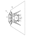
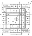
- FIG. 1 is a perspective view of an unmanned aerial vehicle carrying luggage. It is a top view of the goods storage device shown in FIG.
- FIG. 4 is a sectional view taken along the line IV-IV of the load storage device shown in FIG. 1.
- It is a block diagram showing a delivery system including a consignment storage device. It is a sequence diagram which shows the process of the delivery system containing a goods storage device. It is a sequence diagram which shows the process of landing acceptance preparation. It is a figure which shows the storage of the luggage previously conveyed. It is a figure which shows the goods receipt storage apparatus which the landing acceptance preparation was completed. It is a sequence diagram which shows the process of storing a luggage. It is a figure which shows the stage lowered to the storage position. It is a figure which shows the first slide movement. It is a figure which shows the last slide movement. It is a figure which shows the luggage
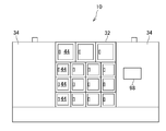
- FIG. 1 is a side view of the cargo storage device according to the embodiment.
- FIG. 2 is a perspective view of an unmanned aerial vehicle carrying luggage.
- the luggage storage device 10 stores the luggage 14 transported by the unmanned aerial vehicle 12.
- the unmanned aerial vehicle 12 is an aircraft on which no person is boarded, and may be, for example, a battery-powered drone or an engine.
- the unmanned aerial vehicle 12 includes a motor and a battery for rotating the propeller 16, and includes a control unit, a storage unit, a communication unit, and a sensor unit (not shown).
- the unmanned aerial vehicle 12 includes a luggage storage unit 18.
- the luggage storage unit 18 includes a frame 20 having a space for storing the luggage 14.
- the frame 20 has a size such that the luggage 14 can be placed and fixed therein.
- the luggage storage unit 18 includes an arm 22 that supports the luggage 14 that is being delivered from falling and a stopper 24 that has a known locking mechanism.
- the luggage 14 is placed on the arm 22 and is fixed so as not to move in the horizontal direction by closing the stopper 24.
- the arm 22 can be opened and closed by the rotation of a motor (not shown). When the unmanned aerial vehicle 12 lands, the arm 22 opens downward, and the load 14 placed on the arm 22 falls by about several cm. It is like this.
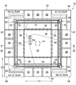
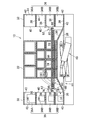
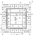
- FIG. 3 is a plan view of the cargo storage device 10 shown in FIG.
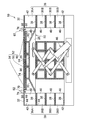
- FIG. 4 is a sectional view taken along line IV-IV of the load receiving and storing device 10 shown in FIG.
- the cargo storage device 10 has a stage 26 for unloading the luggage 14 from the unmanned aerial vehicle 12.
- the stage 26 has a transport surface 28 for unloading the luggage 14.
- the transport surface 28 is also for sliding movement of the luggage 14.
- the stage 26 has an inclined surface 30 that is outwardly lowered outside the transport surface 28.
- the unmanned aerial vehicle 12 is controlled to land on the stage 26 and take off after the unloading of the luggage 14 is completed.
- the stage 26 is large enough to allow the unmanned aerial vehicle 12 to take off and land.
- the cargo storage device 10 has a storage 32 for storing the luggage 14.
- the storage 32 is adjacent to the stage 26.
- the storage 32 is arranged around the stage 26.
- the storage 32 continuously surrounds the stage 26 to prevent intrusion of people.
- the storage 32 is provided with a wall 34 as needed.
- the storage 32 has a plurality of storage spaces 36.
- the plurality of storage spaces 36 are physically separated from each other.
- the plurality of storage spaces 36 include storage spaces 36A and 36B having different sizes.
- the plurality of storage spaces 36 are arranged in the vertical direction and further in the horizontal direction.
- Each of the plurality of storage spaces 36 has a storage surface 38 for storing the luggage 14.
- the storage surface 38 is adjacent to the inclined surface 30 of the stage 26. Between the transport surface 28 and the storage surface 38 is an inclined surface 30 that descends in the direction from the transport surface 28 to the storage surface 38.
- an inclined surface may be provided in the storage 32.
- Each storage space 36 has a carry-in port 40 that can be adjacent to the outer edge of the stage 26.
- Each storage space 36 has an outlet 42 on the opposite side of the carry-in port 40.
- the outlet 42 has a door 44 that can be opened and closed.
- the outlet 42 can be locked and unlocked.
- the take-out port 42 is locked when the luggage 14 is stored.
- the cargo storage device 10 has a lifter 46 for moving the stage 26 up and down.
- the lifter 46 is a known lifting device that uses hydraulic pressure.
- the lifter 46 is configured to lower the stage 26 from the unloading position 48 (see FIG. 9) of the luggage 14 to the storage position 50 (see FIG. 4) corresponding to the selected one of the plurality of storage spaces 36. ..
- the transfer surface 28 is higher than the storage surface 38 when the stage 26 is in the storage position 50, but the transfer surface 28 and the storage surface 38 are connected by the inclined surface 30. As a result, the luggage 14 can be slid from the transport surface 28 to the storage surface 38, and the luggage 14 can be stored in the storage space 36.
- the cargo storage device 10 has a pusher 52 (a jig for pushing) that is movable so as to push the load 14 on the stage 26.
- the pusher 52 includes a first bar 54 extending along the first direction D1 so that the load 14 hits the side surface.
- the pusher 52 includes a second bar 56 extending along a second direction D2 that intersects (for example, is orthogonal to) the first direction D1 so that the luggage 14 hits the side surface.
- the pusher 52 includes a third bar 58 extending along the first direction D1 so that the luggage 14 hits the side surface.
- the pusher 52 includes a fourth bar 60 extending along the second direction D2 so that the luggage 14 hits the side surface.
- the luggage 14 pushed by the pusher 52 slides in the two-dimensional direction (first direction D1 and second direction D2).
- One of the second bar 56 and the fourth bar 60 is used to push the load 14 in the first direction D1.
- One of the first bar 54 and the third bar 58 is used to push the load 14 in the second direction D2.
- At least one of the remaining bars not used to push the load 14 may be used as a guide for sliding movement of the load 14.
- the cargo storage device 10 has an actuator 62 for moving the pusher 52.
- the actuator 62 moves the pusher 52 horizontally. Thereby, the luggage 14 can be slid toward the selected one of the plurality of storage spaces 36.
- the actuator 62 has a mechanism that converts rotational movement into linear movement.
- the actuator 62 includes the first motor 64.
- a first screw shaft 66 is connected to the rotation shaft of the first motor 64.
- a first slider 68 having a screw hole is fitted in the first screw shaft 66.
- the first slider 68 can move in a direction intersecting the first direction D1 (for example, the second direction D2).
- the first slider 68 holds the first bar 54.
- the actuator 62 includes a second slider 70 that is movable in a direction intersecting the second direction D2 (for example, the first direction D1).
- the second slider 70 holds the second bar 56.
- the actuator 62 includes a second motor 72.
- a second screw shaft 74 is connected to the rotation shaft of the second motor 72, and a second slider 70 having a screw hole is fitted in the second screw shaft 74. As a result, the second motor 72 moves the second slider 70.
- the actuator 62 includes a third slider 76 that is movable in a direction intersecting the first direction D1 (for example, the second direction D2).
- the third slider 76 holds the third bar 58.
- the actuator 62 includes a third motor 78.
- a third screw shaft 80 is connected to the rotating shaft of the third motor 78, and a third slider 76 having a screw hole is fitted in the third screw shaft 80. As a result, the third motor 78 moves the third slider 76.
- the actuator 62 includes a fourth slider 82 that can move in a direction intersecting the second direction D2 (for example, the first direction D1).
- the fourth slider 82 holds the fourth bar 60.
- the actuator 62 includes a fourth motor 84.
- a fourth screw shaft 86 is connected to the rotation shaft of the fourth motor 84, and a fourth slider 82 having a screw hole is fitted in the fourth screw shaft 86. As a result, the fourth motor 84 moves the fourth slider 82.
- the luggage 14 can be stored in a selected one of the plurality of storage spaces 36. Can be stored.
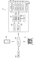
- FIG. 5 is a block diagram showing a delivery system including the goods storage device 10.
- the consignment storage device 10 has a memory 88.
- information regarding the unmanned aerial vehicle 12 [machine identification code (ID), delivery schedule, etc.] and information regarding the package 14 [package identification code (ID), size, password, etc.] Is memorized.
- the cargo storage device 10 has a processor 90.
- the processor 90 is arranged inside the wall 34, for example.
- the processor 90 includes a control unit 92 and a calculation unit 94.
- the processor 90 controls driving (ascending and descending) of the lifter 46.
- the processor 90 controls driving of the actuator 62 (first motor 64, second motor 72, third motor 78, and fourth motor 84).
- the processor 90 controls the security device 96.
- the security device 96 controls locking/unlocking of the take-out port 42 (door 44), and controls opening/closing of the carry-in port 40 as necessary.
- the password required to unlock the outlet 42 (door 44) is input on the control panel 98 (FIG. 1) attached to the wall 34.
- the cargo storage device 10 has a transceiver 100 for communication with the unmanned aerial vehicle 12.
- the storage device 10 has a wired interface 104 for communication with the management system 102.
- the communication is performed via the network 106.
- the unmanned aerial vehicle 12 and the storage device 10 are connected via a network 106 so that data can be transmitted and received.
- a management system 102 for remotely operating the unmanned aerial vehicle 12 is also connected to the network 106 so that data can be transmitted and received.
- the management system 102 is an air traffic control system (UTM: UAV Traffic Management) of the unmanned aerial vehicle 12 (UAV: Unmanned Aerial Vehicle) and manages flight routes and altitudes, data management/analysis, flight permission, real-time monitoring, It plays a role such as preventing entry into the no-fly area.
- UTM UAV Traffic Management
- UAV Unmanned Aerial Vehicle
- the terminal 108 is a portable terminal (including a tablet terminal or a smartphone) operated by a recipient, a personal computer, or the like.
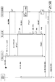
- FIG. 6 is a sequence diagram showing the processing of the delivery system including the goods storage device 10.
- the management system 102 receives a flight application and sets a flight schedule.
- the flight application is issued, for example, by the operator of the unmanned aerial vehicle 12 (the sender of the luggage 14).
- the delivery information is sent to the storage device 10.
- the delivery information includes information about the unmanned aerial vehicle 12 [machine identification code (ID), delivery schedule, etc.] and information about the package 14 [package identification code (ID), size].
- a consignment storage schedule is set.
- the processor 90 (calculation unit 94) selects one of the plurality of storage spaces 36 based on information on which of the plurality of storage spaces 36 is empty.
- the processor 90 (arithmetic unit 94) selects one of the plurality of storage spaces 36 based on the size information of the plurality of storage spaces 36.
- the consignment storage information is sent to the management system 102.
- the receipt storage information includes the landing acceptance date and time, the selected storage space number, and the password.
- the unmanned aerial vehicle 12 Upon receiving the flight permission from the management system 102, the unmanned aerial vehicle 12 departs for the cargo storage device 10.
- the cargo receiving and storing device 10 is notified of the approach of the unmanned aerial vehicle 12.
- the cargo storage device 10 may receive the position information of the unmanned aerial vehicle 12, and based on this, the processor 90 (calculation unit 94) may determine the approach of the unmanned aerial vehicle 12.
- the unmanned aerial vehicle 12 approaches the cargo storage device 10 prepares for landing acceptance.
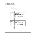
- FIG. 7 is a sequence diagram showing a landing acceptance preparation process.
- FIG. 8 is a figure which shows the storage of the luggage 14 conveyed previously.
- the pusher 52 is above the transport surface 28 at the time when the previously transported luggage 14 is stored in the storage space 36. Therefore, the actuator 62 is controlled to move the pusher 52 to the outside of the transport surface 28 before the start of the next unloading of the load 14. For example, the first bar 54 and the third bar 58 are moved to the outside of the transport surface 28, and the second bar 56 and the fourth bar 60 are moved to the outside of the transport surface 28. That is, when the pusher 52 is not outside the transport surface 28, the pusher 52 is moved because it interferes with the landing of the next unmanned aerial vehicle 12.
- the stage 26 is in the storage position 50 when the previously carried luggage 14 is stored in the storage space 36. Therefore, when the stage 26 is not at the unloading position 48 (FIG. 9), the stage 26 is raised. In this way, the lifter 46 is controlled so as to raise the stage 26 at the storage position 50 to the unloading position 48 before unloading the next load 14. This control may be performed at the latest before the start of unloading of the next luggage 14, and may be performed when the unmanned aerial vehicle 12 approaches (when the approach is detected).
- FIG. 9 is a diagram showing the cargo storage device 10 which is ready for landing acceptance.
- the landing permission is notified from the cargo storage device 10 to the unmanned aerial vehicle 12. This notification may be notified via the management system 102.
- the unmanned aerial vehicle 12 Upon receiving the landing clearance, the unmanned aerial vehicle 12 lands on the stage 26.
- the luggage 14 carried by the unmanned aerial vehicle 12 is unloaded on the stage 26.
- the unmanned aerial vehicle 12 lands on the stage 26 (transport surface 28), it is not necessary to ground the stage 26.
- the first bar 54 and the third bar 58 are located opposite each other outside the transport surface 28 and the second bar 56 and the fourth bar 60 are outside each other on the transport surface 28. Located on the other side.
- the unmanned aerial vehicle 12 is controlled to land on the stage 26 and take off after the unloading of the luggage 14 is completed.
- the unmanned aerial vehicle 12 takes off and moves to a safe position, the unmanned aerial vehicle 12 notifies the cargo storage device 10 that the takeoff is complete.
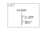
- FIG. 10 is a sequence diagram showing a process of storing the luggage 14.
- the storage space number for storing the luggage 14 is stored in the memory 88 (FIG. 5), and the stage 26 is lowered to the corresponding storage position 50.
- the stage 26 is lowered from the unloading position 48 of the luggage 14 to the storage position 50.
- FIG. 11 is a diagram showing the stage 26 lowered to the storage position 50. Then, the luggage 14 is slid. The slide movement is performed by controlling the actuator 62. The control method is determined by the storage space 36, and the information is stored in the memory 88 in advance.
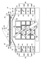
- FIG. 12 is a diagram showing the first slide movement.
- the pusher 52 is moved horizontally and the load 14 is slid. Since this control is performed after the unloading of the luggage 14 is completed (after the unmanned aerial vehicle 12 has taken off), the pusher 52 does not contact the unmanned aerial vehicle 12.
- the luggage 14 slides into the selected storage space 36 by the two-dimensional movement on the transport surface 28.
- the unloaded luggage 14 is first slid to a position facing the carry-in port 40 of the selected storage space 36.
- the first bar 54 and the third bar move the luggage 14 along the second direction D2, and the first bar 54 located downstream of the luggage 14 in the movement direction is used.
- the third bar 58 is not used for sliding movement of the luggage 14, but is used as a guide for guiding the luggage 14 to the storage space 36. By the third bar 58, it is possible to regulate excessive slide movement and inclination of the luggage 14.
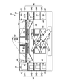
- FIG. 13 is a diagram showing the final slide movement.
- the luggage 14 is slid toward the carry-in port 40 of the selected storage space 36.
- the pusher 52 for example, the second bar 56
- the fourth bar 60 is not used, it is left on the outside of the transport surface 28.
- FIG. 14 is a diagram showing the luggage 14 that enters the storage space 36.
- the luggage 14 that slides due to the horizontal movement of the pusher 52 enters a selected one of the plurality of storage spaces 36. Since the stage 26 has the inclined surface 30, the luggage 14 moves under the unused fourth bar 60. In this way, the luggage 14 is stored in the storage space 36.
- the take-out port 42 of the storage space 36 is controlled to be locked. For example, the door 44 is locked.
- a notification of receipt is sent to the recipient (terminal 108).
- the recipient unlocks the door 44 by electronic authentication such as input of a personal identification number. By doing so, security can be ensured.
- the recipient can unlock the take-out port 42 (door 44) by entering the password in the consignment storage device 10 (control panel 98). Then, the package 14 can be received.
- the take-out port 42 of the storage space 36 is unlocked, the corresponding carry-in port 40 may be closed. By doing so, it is possible to prevent a person from entering or contacting the stage 26 or the other storage spaces 36 through the storage space 36.
- the stage 26 is commonly used for unloading and sliding movement of the luggage 14, and by moving the pusher 52 horizontally, the luggage 14 can be stored in the selected one of the plurality of storage spaces 36. it can. Therefore, it is possible to receive and store the plurality of loads 14 with a simple mechanism.
- the present invention is not limited to the above-described embodiment, and various modifications can be made.
- the configuration described in the embodiments can be replaced with a configuration that is substantially the same, a configuration that achieves the same operational effect, or a configuration that can achieve the same object.
Landscapes
- Engineering & Computer Science (AREA)
- Mechanical Engineering (AREA)
- Food Science & Technology (AREA)
- Aviation & Aerospace Engineering (AREA)
- Warehouses Or Storage Devices (AREA)
- Supports Or Holders For Household Use (AREA)
Abstract
Ce dispositif de réception et de stockage de cargaison (10) comprend un étage (26) pour décharger une cargaison (14) portée par un aéronef sans pilote (12) ; des dispositifs de stockage (32) pour stocker la cargaison (14), les dispositifs de stockage étant adjacents à l'étage (26), et ayant une pluralité d'espaces de stockage (36) aligné au moins dans la direction verticale ; un dispositif de levage (46) pour lever et abaisser l'étage (26) ; un poussoir (52) mobile de façon à pousser la cargaison (14) sur l'étage (26); et un actionneur (62) pour déplacer le poussoir (52). Le dispositif de levage (46) est commandé de manière à abaisser l'étage (26) d'une position de déchargement (48) de la cargaison (14) à une position de stockage (50) correspondant à un espace sélectionné parmi la pluralité d'espaces de réception (36). L'actionneur (62) est commandé de manière à déplacer horizontalement le poussoir (52) afin de faire coulisser le chargement (14) vers celui sélectionné parmi la pluralité d'espaces de réception (36).
Priority Applications (5)
| Application Number | Priority Date | Filing Date | Title |
|---|---|---|---|
| CN201880063274.1A CN111615350A (zh) | 2018-12-26 | 2018-12-26 | 货物接收保管装置及货物接收保管方法 |
| US16/645,796 US11370608B2 (en) | 2018-12-26 | 2018-12-26 | Package receiving and holding apparatus and package receiving and holding method |
| PCT/JP2018/047773 WO2020136742A1 (fr) | 2018-12-26 | 2018-12-26 | Dispositif de réception et de stockage de cargaison et procédé de réception et de stockage de cargaison |
| JP2019540135A JP6646797B1 (ja) | 2018-12-26 | 2018-12-26 | 荷受け保管装置及び荷受け保管方法 |
| EP18932971.7A EP3698680B1 (fr) | 2018-12-26 | 2018-12-26 | Dispositif de réception et de stockage de cargaison et procédé de réception et de stockage de cargaison |
Applications Claiming Priority (1)
| Application Number | Priority Date | Filing Date | Title |
|---|---|---|---|
| PCT/JP2018/047773 WO2020136742A1 (fr) | 2018-12-26 | 2018-12-26 | Dispositif de réception et de stockage de cargaison et procédé de réception et de stockage de cargaison |
Publications (1)
| Publication Number | Publication Date |
|---|---|
| WO2020136742A1 true WO2020136742A1 (fr) | 2020-07-02 |
Family
ID=69568056
Family Applications (1)
| Application Number | Title | Priority Date | Filing Date |
|---|---|---|---|
| PCT/JP2018/047773 Ceased WO2020136742A1 (fr) | 2018-12-26 | 2018-12-26 | Dispositif de réception et de stockage de cargaison et procédé de réception et de stockage de cargaison |
Country Status (5)
| Country | Link |
|---|---|
| US (1) | US11370608B2 (fr) |
| EP (1) | EP3698680B1 (fr) |
| JP (1) | JP6646797B1 (fr) |
| CN (1) | CN111615350A (fr) |
| WO (1) | WO2020136742A1 (fr) |
Cited By (5)
| Publication number | Priority date | Publication date | Assignee | Title |
|---|---|---|---|---|
| JP2020138650A (ja) * | 2019-02-28 | 2020-09-03 | Ihi運搬機械株式会社 | 荷物受取り装置 |
| JP2022109352A (ja) * | 2021-01-15 | 2022-07-28 | ミサワホーム株式会社 | 建物構造 |
| WO2023017609A1 (fr) * | 2021-08-12 | 2023-02-16 | Lomby株式会社 | Boîte de livraison à domicile et système de transport de colis |
| JP2023526750A (ja) * | 2020-04-20 | 2023-06-23 | ダニエル・エス・オウトゥール | 拡張床/アコーディオン構造を備えるドローン・ドッキング・ステーション |
| JP2025060717A (ja) * | 2021-04-15 | 2025-04-10 | Ihi運搬機械株式会社 | 拡張型格納ポート |
Families Citing this family (10)
| Publication number | Priority date | Publication date | Assignee | Title |
|---|---|---|---|---|
| JP6971198B2 (ja) * | 2018-05-29 | 2021-11-24 | 京セラ株式会社 | 電子機器、電子機器の制御方法、及び電子機器の制御プログラム |
| CN110371562B (zh) * | 2018-09-29 | 2020-11-03 | 北京京东尚科信息技术有限公司 | 自提柜 |
| US12408786B2 (en) * | 2020-04-29 | 2025-09-09 | Giuseppe IERADI | Apparatus and system for receiving and delivering parcels from a drone |
| US20210371128A1 (en) * | 2020-05-27 | 2021-12-02 | Luis Rodriguez | Drone Landing Pad System for Receiving Parcels & Packages |
| CN111608095B (zh) * | 2020-06-08 | 2021-01-05 | 广东国安通航智能航空技术发展有限公司 | 一种无人机收纳悬停平台 |
| CN112241179A (zh) * | 2020-09-30 | 2021-01-19 | 北京二郎神科技有限公司 | 配送调度方法、控制器、装置和楼宇 |
| US12059089B1 (en) * | 2020-12-11 | 2024-08-13 | Brian Dunn | Drone landing pad system and related methods |
| US12213609B2 (en) * | 2021-07-09 | 2025-02-04 | Brian Carr | Delivery system and method |
| US20240383681A1 (en) * | 2023-05-19 | 2024-11-21 | DroneUp, LLC | Alignment system for package pick-up and/or drop-off on an unmanned vehicle portal and methods of use |
| US20250302223A1 (en) * | 2024-03-29 | 2025-10-02 | Express Scripts Strategic Development, Inc. | Package locker for packages carried by unmanned aerial vehicles |
Citations (5)
| Publication number | Priority date | Publication date | Assignee | Title |
|---|---|---|---|---|
| JPS5830608U (ja) * | 1981-08-21 | 1983-02-28 | 株式会社岡村製作所 | 昇降式荷出入装置 |
| JPS621092B2 (fr) | 1978-07-18 | 1987-01-12 | Bosch Gmbh Robert | |
| US5416329A (en) * | 1990-05-08 | 1995-05-16 | Wallac Oy | Apparatus for counting liquid scintillation samples |
| JP2017517466A (ja) | 2014-04-11 | 2017-06-29 | ドイチェ ポスト エージー | 無人運搬装置によって貨物を配達するための方法 |
| US20180105289A1 (en) * | 2014-01-02 | 2018-04-19 | Ryan Walsh | Receiving Appliance for Automated Deliveries |
Family Cites Families (18)
| Publication number | Priority date | Publication date | Assignee | Title |
|---|---|---|---|---|
| JP2007076919A (ja) | 2005-08-18 | 2007-03-29 | Murata Mach Ltd | 移載システムおよびそれを備える保管設備 |
| GB2552923A (en) * | 2016-04-13 | 2018-02-21 | Sydney Willcox Brian | Parcel depository |
| CN109804413A (zh) * | 2016-09-30 | 2019-05-24 | 因温特奥股份公司 | 用于递送邮件的辅助系统 |
| EP4191547A1 (fr) * | 2016-10-07 | 2023-06-07 | Quadient Technologies France | Système de casier électronique sécurisé |
| CN206491636U (zh) * | 2016-11-14 | 2017-09-15 | 深圳市智和创兴科技有限公司 | 便于无人机配送使用的快递柜 |
| CN106333595A (zh) * | 2016-11-14 | 2017-01-18 | 深圳市智和创兴科技有限公司 | 便于无人机配送使用的快递柜 |
| CN106552771B (zh) | 2016-12-05 | 2019-02-12 | 顺丰科技有限公司 | 无人机物流地面收纳平台系统及控制方法 |
| CN106938830B (zh) * | 2017-01-22 | 2023-06-06 | 广西大学 | 货物运载装置 |
| JP6201092B1 (ja) | 2017-03-10 | 2017-09-20 | 忍 有田 | 配達物無人自動受取装置 |
| CN207390180U (zh) * | 2017-09-30 | 2018-05-22 | 周鹏跃 | 存取货系统 |
| CN207390181U (zh) * | 2017-09-30 | 2018-05-22 | 周鹏跃 | 存取货系统 |
| CN107720069A (zh) | 2017-10-26 | 2018-02-23 | 安吉智能物联技术有限公司 | 一种智能快递中转柜 |
| CN207645127U (zh) * | 2017-10-26 | 2018-07-24 | 安吉智能物联技术有限公司 | 一种智能快递中转柜 |
| DE112018006071B4 (de) * | 2017-12-27 | 2025-08-21 | Panasonic Intellectual Property Management Co., Ltd. | Formidentifizierungsvorrichtung und zustellbox |
| US20190343317A1 (en) * | 2018-05-11 | 2019-11-14 | Walmart Apollo, Llc | Systems and methods for storing products dropped off by unmanned vehicles and for retrieving the products therefrom |
| WO2020092790A2 (fr) * | 2018-10-31 | 2020-05-07 | Walmart Apollo, Llc | Systèmes et procédés de stockage et de récupération d'objets |
| WO2020118227A1 (fr) * | 2018-12-06 | 2020-06-11 | Walmart Apollo, Llc | Systèmes et procédés de stockage et de récupération d'objets |
| EP3671667A1 (fr) * | 2018-12-18 | 2020-06-24 | Neopost Technologies | Système de casier de colis sécurisé doté d'une sécurité par jetons |
-
2018
- 2018-12-26 EP EP18932971.7A patent/EP3698680B1/fr active Active
- 2018-12-26 CN CN201880063274.1A patent/CN111615350A/zh active Pending
- 2018-12-26 JP JP2019540135A patent/JP6646797B1/ja active Active
- 2018-12-26 WO PCT/JP2018/047773 patent/WO2020136742A1/fr not_active Ceased
- 2018-12-26 US US16/645,796 patent/US11370608B2/en active Active
Patent Citations (5)
| Publication number | Priority date | Publication date | Assignee | Title |
|---|---|---|---|---|
| JPS621092B2 (fr) | 1978-07-18 | 1987-01-12 | Bosch Gmbh Robert | |
| JPS5830608U (ja) * | 1981-08-21 | 1983-02-28 | 株式会社岡村製作所 | 昇降式荷出入装置 |
| US5416329A (en) * | 1990-05-08 | 1995-05-16 | Wallac Oy | Apparatus for counting liquid scintillation samples |
| US20180105289A1 (en) * | 2014-01-02 | 2018-04-19 | Ryan Walsh | Receiving Appliance for Automated Deliveries |
| JP2017517466A (ja) | 2014-04-11 | 2017-06-29 | ドイチェ ポスト エージー | 無人運搬装置によって貨物を配達するための方法 |
Non-Patent Citations (1)
| Title |
|---|
| See also references of EP3698680A4 |
Cited By (11)
| Publication number | Priority date | Publication date | Assignee | Title |
|---|---|---|---|---|
| JP2020138650A (ja) * | 2019-02-28 | 2020-09-03 | Ihi運搬機械株式会社 | 荷物受取り装置 |
| JP7409776B2 (ja) | 2019-02-28 | 2024-01-09 | Ihi運搬機械株式会社 | 荷物受取り装置 |
| JP2023526750A (ja) * | 2020-04-20 | 2023-06-23 | ダニエル・エス・オウトゥール | 拡張床/アコーディオン構造を備えるドローン・ドッキング・ステーション |
| JP7812570B2 (ja) | 2020-04-20 | 2026-02-10 | ダニエル・エス・オウトゥール | 拡張床/アコーディオン構造を備えるドローン・ドッキング・ステーション |
| JP2022109352A (ja) * | 2021-01-15 | 2022-07-28 | ミサワホーム株式会社 | 建物構造 |
| JP7531411B2 (ja) | 2021-01-15 | 2024-08-09 | ミサワホーム株式会社 | 建物構造 |
| JP2025060717A (ja) * | 2021-04-15 | 2025-04-10 | Ihi運搬機械株式会社 | 拡張型格納ポート |
| JP7806198B2 (ja) | 2021-04-15 | 2026-01-26 | Ihi運搬機械株式会社 | 拡張型格納ポート |
| WO2023017609A1 (fr) * | 2021-08-12 | 2023-02-16 | Lomby株式会社 | Boîte de livraison à domicile et système de transport de colis |
| JPWO2023017609A1 (fr) * | 2021-08-12 | 2023-02-16 | ||
| JP7778395B2 (ja) | 2021-08-12 | 2025-12-02 | Lomby株式会社 | 宅配ボックス及び荷物搬送システム |
Also Published As
| Publication number | Publication date |
|---|---|
| US20210214159A1 (en) | 2021-07-15 |
| EP3698680A4 (fr) | 2021-05-05 |
| EP3698680A1 (fr) | 2020-08-26 |
| JPWO2020136742A1 (ja) | 2021-02-15 |
| CN111615350A (zh) | 2020-09-01 |
| EP3698680B1 (fr) | 2023-01-18 |
| JP6646797B1 (ja) | 2020-02-14 |
| US11370608B2 (en) | 2022-06-28 |
Similar Documents
| Publication | Publication Date | Title |
|---|---|---|
| JP6646797B1 (ja) | 荷受け保管装置及び荷受け保管方法 | |
| US9260245B2 (en) | System and method for automatic storage and withdrawal of products with security restrictions | |
| US11526178B2 (en) | Location for unmanned aerial vehicle landing and taking off | |
| JP6201092B1 (ja) | 配達物無人自動受取装置 | |
| CN109205203B (zh) | 用于存放寄送物的接收容器和方法 | |
| CN106232503B (zh) | 用于储存产品的系统、用于使用此系统的方法及布置成在此系统中操作的中央控制单元 | |
| US11806879B2 (en) | Shipping system and control system for secure package delivery | |
| JP2019023020A (ja) | 荷受け設備 | |
| CN115769284A (zh) | 发货系统 | |
| CN110072796A (zh) | 用于输送包裹的电梯和方法 | |
| JP7817476B2 (ja) | 荷物受取り装置 | |
| CN107521400A (zh) | 一种货物运输系统及货物运输方法 | |
| AU2025283683A1 (en) | Staging unmanned aerial vehicles at merchant facilities | |
| JP7001490B2 (ja) | ストッカおよびストッカシステム | |
| CN209506748U (zh) | 无人机投递终端站及无人机投递系统 | |
| US11762393B2 (en) | Shipping system and control system for secure package delivery | |
| JP6678839B1 (ja) | 荷受け仕分け装置及び荷受け仕分け方法 | |
| EP4663553A2 (fr) | Système de manutention de bagages de bout en bout entièrement automatisé incorporant un réclamation de bagages de passager authentifié dans des aéroports | |
| CA3115276A1 (fr) | Emplacement d`atterrissage et de decollage pour un vehicule aerien sans pilote |
Legal Events
| Date | Code | Title | Description |
|---|---|---|---|
| ENP | Entry into the national phase |
Ref document number: 2019540135 Country of ref document: JP Kind code of ref document: A |
|
| ENP | Entry into the national phase |
Ref document number: 2018932971 Country of ref document: EP Effective date: 20200318 |
|
| 121 | Ep: the epo has been informed by wipo that ep was designated in this application |
Ref document number: 18932971 Country of ref document: EP Kind code of ref document: A1 |
|
| NENP | Non-entry into the national phase |
Ref country code: DE |