WO2020136862A1 - Circuit de batterie secondaire et procédé de commande associé - Google Patents
Circuit de batterie secondaire et procédé de commande associé Download PDFInfo
- Publication number
- WO2020136862A1 WO2020136862A1 PCT/JP2018/048444 JP2018048444W WO2020136862A1 WO 2020136862 A1 WO2020136862 A1 WO 2020136862A1 JP 2018048444 W JP2018048444 W JP 2018048444W WO 2020136862 A1 WO2020136862 A1 WO 2020136862A1
- Authority
- WO
- WIPO (PCT)
- Prior art keywords
- secondary battery
- current
- battery pack
- power line
- cell
- Prior art date
- Legal status (The legal status is an assumption and is not a legal conclusion. Google has not performed a legal analysis and makes no representation as to the accuracy of the status listed.)
- Ceased
Links
Images



Classifications
-
- B—PERFORMING OPERATIONS; TRANSPORTING
- B60—VEHICLES IN GENERAL
- B60L—PROPULSION OF ELECTRICALLY-PROPELLED VEHICLES; SUPPLYING ELECTRIC POWER FOR AUXILIARY EQUIPMENT OF ELECTRICALLY-PROPELLED VEHICLES; ELECTRODYNAMIC BRAKE SYSTEMS FOR VEHICLES IN GENERAL; MAGNETIC SUSPENSION OR LEVITATION FOR VEHICLES; MONITORING OPERATING VARIABLES OF ELECTRICALLY-PROPELLED VEHICLES; ELECTRIC SAFETY DEVICES FOR ELECTRICALLY-PROPELLED VEHICLES
- B60L3/00—Electric devices on electrically-propelled vehicles for safety purposes; Monitoring operating variables, e.g. speed, deceleration or energy consumption
- B60L3/04—Cutting off the power supply under fault conditions
-
- B—PERFORMING OPERATIONS; TRANSPORTING
- B60—VEHICLES IN GENERAL
- B60L—PROPULSION OF ELECTRICALLY-PROPELLED VEHICLES; SUPPLYING ELECTRIC POWER FOR AUXILIARY EQUIPMENT OF ELECTRICALLY-PROPELLED VEHICLES; ELECTRODYNAMIC BRAKE SYSTEMS FOR VEHICLES IN GENERAL; MAGNETIC SUSPENSION OR LEVITATION FOR VEHICLES; MONITORING OPERATING VARIABLES OF ELECTRICALLY-PROPELLED VEHICLES; ELECTRIC SAFETY DEVICES FOR ELECTRICALLY-PROPELLED VEHICLES
- B60L50/00—Electric propulsion with power supplied within the vehicle
- B60L50/40—Electric propulsion with power supplied within the vehicle using propulsion power supplied by capacitors
-
- B—PERFORMING OPERATIONS; TRANSPORTING
- B60—VEHICLES IN GENERAL
- B60L—PROPULSION OF ELECTRICALLY-PROPELLED VEHICLES; SUPPLYING ELECTRIC POWER FOR AUXILIARY EQUIPMENT OF ELECTRICALLY-PROPELLED VEHICLES; ELECTRODYNAMIC BRAKE SYSTEMS FOR VEHICLES IN GENERAL; MAGNETIC SUSPENSION OR LEVITATION FOR VEHICLES; MONITORING OPERATING VARIABLES OF ELECTRICALLY-PROPELLED VEHICLES; ELECTRIC SAFETY DEVICES FOR ELECTRICALLY-PROPELLED VEHICLES
- B60L50/00—Electric propulsion with power supplied within the vehicle
- B60L50/50—Electric propulsion with power supplied within the vehicle using propulsion power supplied by batteries or fuel cells
-
- B—PERFORMING OPERATIONS; TRANSPORTING
- B60—VEHICLES IN GENERAL
- B60L—PROPULSION OF ELECTRICALLY-PROPELLED VEHICLES; SUPPLYING ELECTRIC POWER FOR AUXILIARY EQUIPMENT OF ELECTRICALLY-PROPELLED VEHICLES; ELECTRODYNAMIC BRAKE SYSTEMS FOR VEHICLES IN GENERAL; MAGNETIC SUSPENSION OR LEVITATION FOR VEHICLES; MONITORING OPERATING VARIABLES OF ELECTRICALLY-PROPELLED VEHICLES; ELECTRIC SAFETY DEVICES FOR ELECTRICALLY-PROPELLED VEHICLES
- B60L53/00—Methods of charging batteries, specially adapted for electric vehicles; Charging stations or on-board charging equipment therefor; Exchange of energy storage elements in electric vehicles
-
- B—PERFORMING OPERATIONS; TRANSPORTING
- B60—VEHICLES IN GENERAL
- B60L—PROPULSION OF ELECTRICALLY-PROPELLED VEHICLES; SUPPLYING ELECTRIC POWER FOR AUXILIARY EQUIPMENT OF ELECTRICALLY-PROPELLED VEHICLES; ELECTRODYNAMIC BRAKE SYSTEMS FOR VEHICLES IN GENERAL; MAGNETIC SUSPENSION OR LEVITATION FOR VEHICLES; MONITORING OPERATING VARIABLES OF ELECTRICALLY-PROPELLED VEHICLES; ELECTRIC SAFETY DEVICES FOR ELECTRICALLY-PROPELLED VEHICLES
- B60L55/00—Arrangements for supplying energy stored within a vehicle to a power network, i.e. vehicle-to-grid [V2G] arrangements
-
- B—PERFORMING OPERATIONS; TRANSPORTING
- B60—VEHICLES IN GENERAL
- B60L—PROPULSION OF ELECTRICALLY-PROPELLED VEHICLES; SUPPLYING ELECTRIC POWER FOR AUXILIARY EQUIPMENT OF ELECTRICALLY-PROPELLED VEHICLES; ELECTRODYNAMIC BRAKE SYSTEMS FOR VEHICLES IN GENERAL; MAGNETIC SUSPENSION OR LEVITATION FOR VEHICLES; MONITORING OPERATING VARIABLES OF ELECTRICALLY-PROPELLED VEHICLES; ELECTRIC SAFETY DEVICES FOR ELECTRICALLY-PROPELLED VEHICLES
- B60L58/00—Methods or circuit arrangements for monitoring or controlling batteries or fuel cells, specially adapted for electric vehicles
-
- H—ELECTRICITY
- H02—GENERATION; CONVERSION OR DISTRIBUTION OF ELECTRIC POWER
- H02H—EMERGENCY PROTECTIVE CIRCUIT ARRANGEMENTS
- H02H7/00—Emergency protective circuit arrangements specially adapted for specific types of electric machines or apparatus or for sectionalised protection of cable or line systems, and effecting automatic switching in the event of an undesired change from normal working conditions
- H02H7/18—Emergency protective circuit arrangements specially adapted for specific types of electric machines or apparatus or for sectionalised protection of cable or line systems, and effecting automatic switching in the event of an undesired change from normal working conditions for batteries; for accumulators
-
- H—ELECTRICITY
- H02—GENERATION; CONVERSION OR DISTRIBUTION OF ELECTRIC POWER
- H02J—ELECTRIC POWER NETWORKS; CIRCUIT ARRANGEMENTS OR SYSTEMS FOR SUPPLYING OR DISTRIBUTING ELECTRIC POWER; SYSTEMS FOR STORING ELECTRIC ENERGY
- H02J7/00—Circuit arrangements for charging or discharging batteries or for supplying loads from batteries
-
- Y—GENERAL TAGGING OF NEW TECHNOLOGICAL DEVELOPMENTS; GENERAL TAGGING OF CROSS-SECTIONAL TECHNOLOGIES SPANNING OVER SEVERAL SECTIONS OF THE IPC; TECHNICAL SUBJECTS COVERED BY FORMER USPC CROSS-REFERENCE ART COLLECTIONS [XRACs] AND DIGESTS
- Y02—TECHNOLOGIES OR APPLICATIONS FOR MITIGATION OR ADAPTATION AGAINST CLIMATE CHANGE
- Y02T—CLIMATE CHANGE MITIGATION TECHNOLOGIES RELATED TO TRANSPORTATION
- Y02T10/00—Road transport of goods or passengers
- Y02T10/60—Other road transportation technologies with climate change mitigation effect
- Y02T10/70—Energy storage systems for electromobility, e.g. batteries
-
- Y—GENERAL TAGGING OF NEW TECHNOLOGICAL DEVELOPMENTS; GENERAL TAGGING OF CROSS-SECTIONAL TECHNOLOGIES SPANNING OVER SEVERAL SECTIONS OF THE IPC; TECHNICAL SUBJECTS COVERED BY FORMER USPC CROSS-REFERENCE ART COLLECTIONS [XRACs] AND DIGESTS
- Y02—TECHNOLOGIES OR APPLICATIONS FOR MITIGATION OR ADAPTATION AGAINST CLIMATE CHANGE
- Y02T—CLIMATE CHANGE MITIGATION TECHNOLOGIES RELATED TO TRANSPORTATION
- Y02T10/00—Road transport of goods or passengers
- Y02T10/60—Other road transportation technologies with climate change mitigation effect
- Y02T10/7072—Electromobility specific charging systems or methods for batteries, ultracapacitors, supercapacitors or double-layer capacitors
-
- Y—GENERAL TAGGING OF NEW TECHNOLOGICAL DEVELOPMENTS; GENERAL TAGGING OF CROSS-SECTIONAL TECHNOLOGIES SPANNING OVER SEVERAL SECTIONS OF THE IPC; TECHNICAL SUBJECTS COVERED BY FORMER USPC CROSS-REFERENCE ART COLLECTIONS [XRACs] AND DIGESTS
- Y02—TECHNOLOGIES OR APPLICATIONS FOR MITIGATION OR ADAPTATION AGAINST CLIMATE CHANGE
- Y02T—CLIMATE CHANGE MITIGATION TECHNOLOGIES RELATED TO TRANSPORTATION
- Y02T90/00—Enabling technologies or technologies with a potential or indirect contribution to GHG emissions mitigation
- Y02T90/10—Technologies relating to charging of electric vehicles
- Y02T90/14—Plug-in electric vehicles
Definitions
- the present invention relates to a secondary battery circuit and the like suitable for use as a power source for electric devices and automobiles.
- Patent Document 1 discloses a circuit including a battery that supplies electric power to a traveling motor of an electric vehicle and a main relay that supplies or cuts off electric power of the battery to the traveling motor.
- a device called a contactor for example, is applied to the main relay.
- the contactor shuts off the current in the power line of the secondary battery circuit according to the signal input from the control circuit. As a result, loads such as the secondary battery circuit and the traveling motor are protected from overcurrent.
- the present invention has been made in order to solve the above problems, and its main object is to provide a secondary battery circuit having a simple structure and further improved safety.
- the present invention includes a secondary battery pack having cells, a power supply unit for supplying power to the secondary battery pack or a load supplied from the secondary battery pack, the secondary battery pack and the power supply unit or the load.
- a secondary battery circuit including a power line connected in series, the first current interrupting device being connected in series to the power line to cut off the current of the power line, and the temperature rise of the cell, A second current interruption device for interrupting the output current of the cell.
- the second current interruption device has a fixed contact, an elastic portion that elastically deforms, and a movable contact at a tip portion of the elastic portion, and the movable contact is the fixed contact.
- the movable piece that is pressed against and comes into contact with the movable piece deforms as the temperature of the cell rises, so that the movable piece changes from the conductive state in which the movable contact contacts the fixed contact to the movable contact to the fixed contact. It is desirable to have a thermally responsive element that shifts to a separated blocking state.
- the power supply unit or the load includes a motor generator.
- the secondary battery circuit according to the present invention includes a control unit that controls the operation of the first current interruption device.
- control unit controls the operation of the first current cutoff device based on the voltage across the secondary battery pack.
- control unit detect the both-end voltage that fluctuates as the second current cutoff device cuts off the output current of the cell.
- the secondary battery circuit it is desirable to control the operation of the first current cutoff device based on the current of the power line.
- control unit detect the current that fluctuates as the second current cutoff device cuts off the output current of the cell.
- the present invention provides a secondary battery pack having cells, a power supply unit for supplying power to the secondary battery pack or a load supplied from the secondary battery pack, the secondary battery pack and the power supply unit or the load.
- a method for controlling a secondary battery circuit comprising: a power line that connects a power line and a power line in series; and a current cutoff device that is connected in series to the power line and cuts off a current in the power line. The first step of detecting the voltage across the cell, the second step of cutting off the output current of the cell due to the temperature rise of the cell, the third step of detecting the fluctuation of the voltage across the cell, and the third step. And a fourth step of operating the current interruption device based on the detected variation.
- the secondary battery circuit of the present invention is connected in series to the power line, and cuts off the output current of the cell with the first current cutoff device for cutting off the current of the power line and the temperature rise of the cell. And the second current interruption device.
- the second current cutoff device has both a function as a temperature sensor for detecting a temperature rise of the cell and a function of cutting off the output current of the cell independently.
- the safety of the secondary battery circuit can be enhanced with a simple configuration. For example, even if the voltage across the secondary battery pack is not abnormal and the first current cutoff device does not operate and the cell is overheated for some reason, the second current cutoff is performed. When the device operates, overheating of the cell is stopped. Furthermore, when the resistance of the power line increases with the operation of the second current cutoff device, it becomes possible to protect the secondary battery pack and the load by operating the first current cutoff device.
- the voltage across the secondary battery pack is detected in the first step, and the output current of the cell is shut off as the temperature of the cell rises in the second step. ..
- the voltage across the rechargeable battery pack that fluctuates by interrupting the output current of the cell in the second step is detected in the third step, and the detected fluctuation in the fourth step. Based on the above, the current interruption device is operated. As a result, the output current of the cell is cut off in the second step, and then the current cutoff device operates in the fourth step. Therefore, the safety of the secondary battery circuit can be enhanced with a simple structure.
- FIG. 3 is a circuit diagram of a secondary battery circuit according to an embodiment of the present invention.
- FIG. FIG. 1 is a perspective view before assembly showing a schematic configuration of a breaker according to an embodiment of the present invention. Sectional drawing which shows the said breaker in a normal charge or discharge state. Sectional drawing which shows the said breaker at the time of an overcharge state, an abnormality, etc. The flowchart which shows the procedure of the control method of the secondary battery circuit of this invention.
- FIG. 1 shows a secondary battery circuit 100 according to an embodiment of the present invention.
- the secondary battery circuit 100 in the present embodiment is a circuit applied to an automobile that can be driven by a motor.
- the secondary battery circuit 100 includes a secondary battery pack 110, a motor generator 120, and a power line 130.
- the secondary battery pack 110 has cells 111 that store electric charges.
- the secondary battery pack 110 of this embodiment has a plurality of cells 111.
- the cells 111 are connected in series.
- the cells 111 may be connected in parallel (parallel and series). Further, the cell 111 may be a single cell.
- the motor generator 120 functions as a power supply unit 121 that supplies power to the secondary battery pack 110 and a load 122 that receives power from the secondary battery pack 110 in the secondary battery circuit 100.
- the motor generator 120 converts the kinetic energy of the vehicle into electric energy to generate power, and charges the secondary battery pack 110.
- the motor generator 120 converts the electric energy supplied with the discharge of the secondary battery pack 110 into kinetic energy to drive the vehicle.
- the power supply unit 121 and the load 122 may be provided separately in the secondary battery circuit 100, or may be provided with only one of them. Further, the load 122 may be a device other than a motor for traveling, for example, an image display device such as a liquid display.
- the power line 130 connects the secondary battery pack 110 and the motor generator 120 in series. Charging/discharging of the secondary battery pack 110 is performed via the power line 130.
- a plurality of power lines 130 may be provided according to the number of power supply units 121 and loads 122.
- a first current interruption device 140 is provided on the power line 130.
- the first current cutoff device 140 is connected in series to the power line 130, and cuts off the current of the power line 130 when the secondary battery circuit 100 is abnormal.
- the first current interruption device 140 protects the motor generator 120, the power line 130, and the like from an abnormality in the secondary battery circuit 100.
- a device such as a contactor 141 is applied to the first current interruption device 140.
- the contactor 141 opens and closes a switch (contact) using, for example, an electromagnetic force generated by a coil or the like.
- a switch contact
- the switch in the contactor 141 is opened, the current in the power line 130 is cut off.
- the secondary battery pack 110, the motor generator 120, the power line 130, and the like are protected from the abnormality of the secondary battery circuit 100.
- the secondary battery circuit 100 includes a secondary battery pack 110 and a second current interruption device 112.
- each cell 111 is provided with one second current blocking device 112.
- the second current interruption device 112 is provided adjacent to each cell 111, and is connected in series with each adjacent cell 111.
- One second current blocking device 112 may be provided for each of the plurality of cells 111.
- the second current cutoff device 112 cuts off the output current of each cell 111 as the temperature of each cell 111 rises.
- the second current cutoff device 112 has both a function as a temperature sensor for detecting the temperature rise of each cell 111 and a function for cutting off the output current of the cell 111 independently.
- the safety of the secondary battery circuit 100 can be enhanced with a simple configuration. For example, even if no abnormality is found in the voltage across the secondary battery pack 110, the first current cutoff device 140 does not operate, and any cell 111 overheats for some reason, the second current cutoff is performed. When the device 112 operates, overheating of the cell 111 is stopped. Furthermore, when the resistance of the power line 130 increases with the operation of the second current cutoff device 112, the first current cutoff device 140 operates to protect the secondary battery pack 110, the motor generator 120, and the power line 130. Will also be possible.
- the breaker 1 is applied to the second current interruption device 112 of the present embodiment as an element capable of instantaneously interrupting the current in response to temperature rise.
- the breaker 1 is mounted on an electric device or the like and protects the electric device from excessive temperature rise or overcurrent.
- the breaker 1 includes a fixed piece 2 having a fixed contact 21, a movable piece 4 having a movable contact 41 at its tip, a heat responsive element 5 that deforms with a change in temperature, a fixed piece 2, a movable piece 4 and a heat responsive element. It is configured by a case 10 or the like that houses the element 5.
- the case 10 includes a case body (first case) 7, a lid member (second case) 8 mounted on the upper surface of the case body 7, and the like.
- the fixing piece 2 is formed with a terminal 22 exposed from the case 10.
- a terminal 42 is formed on the movable piece 4 exposed from the case 10.
- the fixing piece 2 is formed, for example, by pressing a plate-shaped metal material containing copper as a main component (other than this, a metal plate of copper-titanium alloy, nickel silver, brass, etc.).
- the fixing piece 2 is embedded in the case body 7 by insert molding and is housed in the case body 7 with the terminals 22 exposed to the outside of the case body 7.
- the fixed contact 21 is formed at a position facing the movable contact 41 by clad, plating or coating of a material having good conductivity such as silver, nickel, nickel-silver alloy, copper-silver alloy, gold-silver alloy. It is exposed from a part of the opening 73 a formed inside the case body 7.
- the terminal 22 is formed at one end of the fixed piece 2.
- the terminal 22 projects outward from the side wall at the edge of the case body 7.
- the terminal 22 is electrically connected to the power line 130 of the secondary battery circuit 100.
- the surface on the side where the fixed contact 21 is formed (that is, the upper surface in FIG. 2) is the A surface, and the opposite surface is the B surface. doing.
- the direction from the fixed contact 21 to the movable contact 41 is defined as the first direction and the direction opposite to the first direction is defined as the second direction
- the A surface faces the first direction
- the B surface faces the second direction.
- the movable piece 4 is formed into an arm shape symmetrical with respect to the center line in the longitudinal direction by pressing a plate-shaped metal material containing copper as a main component.
- a movable contact 41 is formed at the longitudinal end of the movable piece 4.
- the movable contact 41 is formed of, for example, a material similar to that of the fixed contact 21, and is joined to the distal end portion of the movable piece 4 by a method such as welding, clad, crimping, or the like.
- a terminal 42 electrically connected to the power line 130 of the secondary battery circuit 100 is formed at the other end of the movable piece 4 in the longitudinal direction.
- the terminal 42 projects outward from the side wall at the edge of the case body 7.
- One of the terminals 22 and 42 is connected to the positive electrode of the cell 111, and the other is connected to the power line 130 on the side of the first current interruption device 140 or the negative electrode of the cell 111.
- the movable piece 4 has a contact portion 43 and an elastic portion 44 between the movable contact 41 and the terminal 42.
- the contact portion 43 contacts the case body 7 and the lid member 8 between the terminal 42 and the elastic portion 44.
- the contact portion 43 has a protruding portion 43a that protrudes like a wing in the lateral direction of the movable piece 4. Since the protrusion 43a is provided, the contact portion 43 is sandwiched between the case body 7 and the lid member 8 in a wide and large area, and the movable piece 4 is firmly fixed to the case 10.
- the elastic portion 44 extends from the contact portion 43 to the movable contact 41 side.
- the movable piece 4 is cantilevered by the case 10 at the abutment portion 43 on the proximal end side of the elastic portion 44, and is elastically deformed in this state to be formed at the distal end portion of the elastic portion 44.
- the movable contact 41 that is present is pressed against the side of the fixed contact 21 and comes into contact with it, and the fixed piece 2 and the movable piece 4 can be energized.
- the movable piece 4 is curved or bent in the elastic portion 44 by press working.
- the degree of bending or bending is not particularly limited as long as the thermoresponsive element 5 can be housed, and may be appropriately set in consideration of the elastic force at the operating temperature and the returning temperature, the pressing force of the movable contact 41, and the like.
- a pair of protrusions 44 a and 44 b is formed on the surface B of the elastic portion 44 so as to face the thermoresponsive element 5.
- the protrusion 44a protrudes toward the heat responsive element 5 on the base end side and contacts the heat responsive element 5 in a blocked state.
- the protrusion 44b protrudes toward the thermal responsive element 5 on the tip side (that is, the movable contact 41 side) of the protrusion 44a, and contacts the thermal responsive element 5 in a blocked state.
- the thermal responsive element 5 is deformed by overheating, the thermal responsive element 5 contacts the protrusions 44a and 44b, the deformation of the thermal responsive element 5 is transmitted to the elastic portion 44 via the protrusions 44a and 44b, and the movable piece 4 moves.
- the tip is pushed up (see Fig. 4).
- the heat-responsive element 5 shifts the state of the movable piece 4 from a conductive state in which the movable contact 41 contacts the fixed contact 21 to a shut-off state in which the movable contact 41 is separated from the fixed contact 21.
- the heat responsive element 5 has an initial shape in which the cross section is curved in an arc shape, and is formed in a plate shape by stacking thin plate materials having different thermal expansion coefficients. When the operating temperature is reached due to overheating, the curved shape of the heat responsive element 5 reversely warps with snap motion, and is restored when the temperature falls below the return temperature due to cooling.
- the initial shape of the heat responsive element 5 can be formed by pressing.
- thermoresponsive element 5 are not particularly limited as long as the elastic portion 44 of the movable piece 4 is pushed up by the backward warping operation of the thermoresponsive element 5 at the desired temperature and returned to its original state by the elastic force of the elastic portion 44.
- a rectangular shape is desirable from the viewpoint of productivity and efficiency of the backward warping operation.
- thermoresponsive element 5 As the material of the heat responsive element 5, two kinds of plate-shaped metal materials, which are made of various alloys such as nickel silver, brass and stainless steel and have different coefficients of thermal expansion, are laminated and used in combination according to the required conditions. To be done.
- a material of the thermoresponsive element 5 that can obtain a stable operation temperature and a return temperature it is desirable to combine a copper-nickel-manganese alloy on the high expansion side and an iron-nickel alloy on the low expansion side.
- a material in which an iron-nickel-chromium alloy is used on the high expansion side and an iron-nickel alloy is used on the low expansion side can be mentioned.
- a material in which an iron-nickel-chromium alloy is combined on the high expansion side and an iron-nickel-cobalt alloy is combined on the low expansion side can be mentioned.
- the case body 7 and the lid member 8 that form the case 10 are formed of a thermoplastic resin such as flame-retardant polyamide, polyphenylene sulfide (PPS), liquid crystal polymer (LCP), polybutylene terephthalate (PBT), etc., which has excellent heat resistance. Has been done. A material other than the resin may be applied as long as the characteristics equal to or higher than those of the resin described above can be obtained.
- a thermoplastic resin such as flame-retardant polyamide, polyphenylene sulfide (PPS), liquid crystal polymer (LCP), polybutylene terephthalate (PBT), etc.
- the case body 7 is formed with a concave portion 73 which is an internal space for accommodating the movable piece 4, the thermoresponsive element 5, and the like.
- the recess 73 has openings 73a and 73b for housing the movable piece 4, an opening 73c for housing the movable piece 4 and the thermoresponsive element 5, and the like.
- the edges of the movable piece 4 and the thermal responsive element 5 incorporated in the case body 7 are brought into contact with each other by a frame formed inside the recess 73, and are guided when the thermal responsive element 5 warps backward.
- the lid member 8 may be embedded with a metal plate containing copper or the like as a main component or a metal plate such as stainless steel by insert molding.
- the metal plate appropriately abuts against the surface A of the movable piece 4, restricts the movement of the movable piece 4, and contributes to the downsizing of the breaker 1 while increasing the rigidity and strength of the lid member 8 and the case 10 as a housing. To do.
- the openings 73a, 73b, 73c, etc. of the case body 7 accommodating the fixed piece 2 (fixed contact 21), the movable piece 4 (movable contact 41, elastic portion 44), the thermoresponsive element 5, etc. are closed.
- the lid member 8 is attached to the case body 7.
- the case body 7 and the lid member 8 are joined by ultrasonic welding, for example.
- the breaker 1 is assembled with the terminals 22 and 42 exposed.
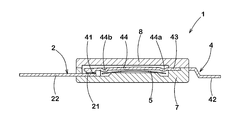
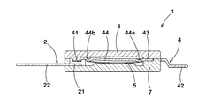
- FIG. 3 and 4 show an outline of the operation of the breaker 1.
- FIG. 3 shows the operation of the breaker 1 in a normal charging or discharging state.
- the thermal response element 5 maintains the initial shape before reverse warpage.
- the movable contact 41 is pressed toward the fixed contact 21 by the elastic portion 44, the movable contact 41 and the fixed contact 21 come into contact with each other, and the fixed piece 2 and the movable piece 4 of the breaker 1 are brought into a conductive state.
- the heat responsive element 5 may be separated from the protrusions 44a and 44b of the movable piece 4 in the conductive state. As a result, the contact pressure between the movable contact 41 and the fixed contact 21 is increased, and the contact resistance between them is reduced.
- FIG. 4 shows the operation of the breaker 1 in an overcharged state or an abnormality.
- the thermal responsive element 5 that has reached the operating temperature warps backward and comes into contact with the elastic portion 44 of the movable piece 4, and the elastic portion 44 is pushed up so that the fixed contact 21 and the movable contact 41 are formed. Are separated. At this time, the current flowing between the fixed contact 21 and the movable contact 41 is cut off.
- thermoresponsive element 5 When the overcharged state is released or the abnormal state is resolved, the thermoresponsive element 5 returns to the reset temperature and restores the original initial shape. Then, due to the elastic force of the elastic portion 44 of the movable piece 4, the movable contact 41 and the fixed contact 21 come into contact again, the circuit is released from the disconnected state, and the conductive state shown in FIG. 3 is restored.
- the secondary battery circuit 100 of this embodiment includes a control unit 150 that controls the operation of the first current interruption device 140. More specifically, the control unit 150 controls the current supplied to the coil or the like of the contactor 141 (that is, the current for opening and closing the switch in the contactor 141). In the present embodiment, a so-called BMU (Battery Management Unit) is applied as the control unit 150.
- BMU Battery Management Unit
- the control unit 150 controls the operation of the contactor 141 based on the voltage across the secondary battery pack 110.
- the voltage across the secondary battery pack 110 is detected by the voltage detector 160.
- the voltage detection unit 160 detects the voltage across the secondary battery pack 110 during charging and discharging.
- the control unit 150 controls the current supplied to the coil or the like of the contactor 141 based on the voltage across the secondary battery pack 110 detected by the voltage detection unit 160.
- the voltage across the secondary battery pack 110 fluctuates as the breaker 1 cuts off the output current of any of the cells 111.
- the control unit 150 detects the fluctuating voltage across the secondary battery pack 110 and controls the operation of the contactor 141. For example, when the control unit 150 monitors the voltage across the secondary battery pack 110 and detects that the voltage across the secondary battery pack 110 is less than a predetermined threshold value, one of the cells 111 is overheated. Then, the contactor 141 is determined to be abnormal and the contactor 141 is turned off. As a result, the circuit of the power line 130 is cut off at a plurality of positions of the breaker 1 and the contactor 141, so that the safety of the secondary battery circuit 100 is further enhanced.
- the circuit of the power line 130 is cut off in the contactor 141, so that the potential difference between the fixed contact 21 and the movable contact 41 of the breaker 1 becomes zero. As a result, the occurrence of an arc or the like between the fixed contact 21 and the movable contact 41 is suppressed, and the safety of the secondary battery circuit 100 is further enhanced.
- a battery sensor is provided as a device that detects the voltage and temperature of the battery and outputs a corresponding pulse.
- the output current of the cell in which an abnormality has occurred cannot be directly interrupted by the battery sensor itself, so there is a risk that the safety of the device cannot be sufficiently ensured.
- an IC having high processing capability is required as the battery sensor, which causes an increase in the cost of the device.
- the breaker 1 applied as the second current interruption device 112 has a function as a temperature sensor for detecting a temperature rise of each cell 111, and the breaker 1 functions as a single cell of the cell 111. Since the secondary battery circuit 100 also has a function of cutting off the output current, it is possible to easily realize the secondary battery circuit 100 having a simple and inexpensive structure and having extremely high safety.
- the control unit 150 may be configured to control the operation of the contactor 141 based on the current of the power line 130.
- the current of the power line 130 is detected by the current detector 170.
- the control unit 150 detects the current that fluctuates as the second current cutoff device 112 cuts off the output current of the cell 111.
- control unit 150 monitors the current of the power line 130 and detects that the current of the power line 130 is less than a predetermined lower limit threshold value, one of the cells 111 is abnormal due to overheating. After being certified, the contactor 141 is turned off. This further enhances the safety of the secondary battery circuit 100. Further, when the control unit 150 monitors the current of the power line 130 and detects that the current of the power line 130 exceeds a predetermined upper limit threshold value, it is determined that an abnormality such as a short circuit has occurred in the power line 130. After being certified, the contactor 141 is turned off. This further enhances the safety of the secondary battery circuit 100.
- FIG. 5 shows a control method of the secondary battery circuit 100 shown in FIG.
- the control method includes the first step S1 to the fourth step S4.
- the voltage detector 160 detects the voltage across the secondary battery pack 110. The detected voltage is input to the control unit 150 and monitored by the control unit 150.
- the breaker 1 monitors the temperature rise of the cell 111.
- the breaker 1 cuts off the output current of the cell 111.
- the voltage across the secondary battery pack 110 drops.
- the fluctuation (voltage drop) of the voltage across the secondary battery pack 110 caused by the breaker 1 blocking the output current of the cell 111 in the second step S2 is controlled by the voltage detection unit 160 and the control unit 150. To be detected.
- the control unit 150 supplies a current to the coil of the contactor 141 based on the fluctuation of the voltage across the secondary battery pack 110 to turn off the contactor 141.
- the breaker 1 cuts off the output current of the cell 111, and the contactor 141 cuts off the circuit of the power line 130. Therefore, according to this control method, the safety of the secondary battery circuit 100 is enhanced with a simple configuration.
- the present control method can also be applied to a secondary battery circuit to which the first current interruption device 140 other than the contactor 141 and the second current interruption device 112 other than the breaker 1 are applied.
- the secondary battery circuit 100 includes at least a secondary battery pack 110 having cells 111, a power supply unit 121 for supplying power to the secondary battery pack 110 or a load 122 supplied from the secondary battery pack 110, and a secondary battery.
- a power line 130 that connects the pack 110 and the power supply unit 121 or the load 122 in series, is connected in series to the power line 130, and cuts off the current in the power line 130. It suffices to have the second current interruption device 112 that interrupts the output current of the cell 111 as the temperature rises.
- a fuse with a heater may be applied to the first current interruption device 140.
- the control unit 150 is configured to supply a current to the heater and disconnect the fuse based on the voltage across the secondary battery pack 110 or the current in the power line 130.
- a PTC (Positive Temperature Coefficient) thermistor can be applied to the second current cutoff device 112. In this case, as the temperature of the cell 111 rises, the resistance value of the PTC thermistor sharply increases, and the output current of the cell 111 is substantially cut off.
- the secondary battery circuit 100 may have a configuration in which either the voltage detection unit 160 or the current detection unit 170 is provided.
- the present invention is also applicable to a stationary power storage system for business or home, in addition to the power supply circuit of the automobile described above.
- a so-called one-shot type breaker that operates only once may be applied to the second current interruption device 112 of the present embodiment.
- a breaker having a form having a self-holding circuit using a PTC thermistor, as disclosed in WO2011/105175 can be applied.
- the movable piece 4 may be integrally formed with the thermoresponsive element 5 by forming the movable piece 4 with a laminated metal such as bimetal or trimetal. ..
- a laminated metal such as bimetal or trimetal. ..
- the structure of the breaker 1 is simplified, and the secondary battery pack 110 can be downsized.
- the movable piece 4 is integrally formed from the elastic portion 44 to the terminal 42.
- the movable piece 4 in the form of being separated into the movable arm on the side of the movable contact 41 and the terminal piece on the side of the terminal 42 may be applied to the present invention as shown in 2017-37757.
- the movable arm and the terminal piece may be fixed by welding or the like.
- the terminal piece on the terminal 42 side may be insert-molded in the case body 7 together with the fixing piece 2 and the like.
Landscapes
- Engineering & Computer Science (AREA)
- Power Engineering (AREA)
- Transportation (AREA)
- Mechanical Engineering (AREA)
- Life Sciences & Earth Sciences (AREA)
- Sustainable Development (AREA)
- Sustainable Energy (AREA)
- Protection Of Static Devices (AREA)
- Charge And Discharge Circuits For Batteries Or The Like (AREA)
- Electric Propulsion And Braking For Vehicles (AREA)
- Breakers (AREA)
Abstract
Un circuit de batterie secondaire (100) comprend: un bloc-batterie secondaire (110) qui a des éléments (111); une unité d'alimentation (121) qui alimente en énergie le bloc-batterie secondaire (110), ou une charge (122) auquel le bloc-batterie secondaire (110) fournit de l'énergie; et une ligne d'alimentation (130) qui connecte en série la batterie secondaire (110) à l'unité d'alimentation (121) ou à la charge (122) en série. Le circuit de batterie secondaire (100) est pourvu d'un premier dispositif d'interruption de courant (140) qui est connecté en série à la ligne électrique (130) et interrompt le courant dans la ligne électrique (130), et un second dispositif d'interruption de courant (112) qui interrompt un courant de sortie des éléments (111) lorsque la température des éléments (111) augmente.
Priority Applications (3)
| Application Number | Priority Date | Filing Date | Title |
|---|---|---|---|
| JP2020562263A JPWO2020136862A1 (ja) | 2018-12-28 | 2018-12-28 | 2次電池回路及びその制御方法 |
| CN201880099915.9A CN113165528A (zh) | 2018-12-28 | 2018-12-28 | 二次电池电路及其控制方法 |
| PCT/JP2018/048444 WO2020136862A1 (fr) | 2018-12-28 | 2018-12-28 | Circuit de batterie secondaire et procédé de commande associé |
Applications Claiming Priority (1)
| Application Number | Priority Date | Filing Date | Title |
|---|---|---|---|
| PCT/JP2018/048444 WO2020136862A1 (fr) | 2018-12-28 | 2018-12-28 | Circuit de batterie secondaire et procédé de commande associé |
Publications (1)
| Publication Number | Publication Date |
|---|---|
| WO2020136862A1 true WO2020136862A1 (fr) | 2020-07-02 |
Family
ID=71126244
Family Applications (1)
| Application Number | Title | Priority Date | Filing Date |
|---|---|---|---|
| PCT/JP2018/048444 Ceased WO2020136862A1 (fr) | 2018-12-28 | 2018-12-28 | Circuit de batterie secondaire et procédé de commande associé |
Country Status (3)
| Country | Link |
|---|---|
| JP (1) | JPWO2020136862A1 (fr) |
| CN (1) | CN113165528A (fr) |
| WO (1) | WO2020136862A1 (fr) |
Cited By (3)
| Publication number | Priority date | Publication date | Assignee | Title |
|---|---|---|---|---|
| TWI797641B (zh) * | 2020-06-17 | 2023-04-01 | 日商肖特(日本)股份有限公司 | 保護電路 |
| WO2023058314A1 (fr) * | 2021-10-04 | 2023-04-13 | ボーンズ株式会社 | Bloc-batterie secondaire |
| JP2024526530A (ja) * | 2021-09-03 | 2024-07-19 | ビーワイディー カンパニー リミテッド | 配電器、車両の充電配電システム、車両及び充電スタンド |
Citations (8)
| Publication number | Priority date | Publication date | Assignee | Title |
|---|---|---|---|---|
| JPS63279594A (ja) * | 1987-05-11 | 1988-11-16 | Toshiba Corp | 調理器 |
| JPH0752067A (ja) * | 1993-08-13 | 1995-02-28 | Matsushita Electric Works Ltd | 電池式刃物工具 |
| JPH10100079A (ja) * | 1996-09-30 | 1998-04-21 | Sanyo Electric Co Ltd | 電動工具用のパック電池 |
| JP2001057206A (ja) * | 1999-08-19 | 2001-02-27 | Nec Mobile Energy Kk | 電流遮断装置を備えた密閉型電池 |
| JP2003234055A (ja) * | 2002-02-12 | 2003-08-22 | Texas Instr Japan Ltd | 過電圧保護装置およびそれを用いたバッテリー保護システム |
| JP2010226894A (ja) * | 2009-03-24 | 2010-10-07 | Sanyo Electric Co Ltd | 車両用電源装置及びその冷却方法 |
| JP2013230023A (ja) * | 2012-04-26 | 2013-11-07 | Toyota Motor Corp | 蓄電システムおよび、電気部品の異常判別方法 |
| JP2015128361A (ja) * | 2013-11-29 | 2015-07-09 | 日立マクセル株式会社 | 電池保護回路および電池パック |
Family Cites Families (7)
| Publication number | Priority date | Publication date | Assignee | Title |
|---|---|---|---|---|
| CN1497766A (zh) * | 2002-10-08 | 2004-05-19 | 阿尔卑斯电气株式会社 | 电池组装置 |
| JP2005124329A (ja) * | 2003-10-17 | 2005-05-12 | Alps Electric Co Ltd | 電池保護装置及びこれを用いた電池パック |
| US9024586B2 (en) * | 2010-10-14 | 2015-05-05 | GM Global Technology Operations LLC | Battery fault tolerant architecture for cell failure modes series bypass circuit |
| JP2013074707A (ja) * | 2011-09-27 | 2013-04-22 | Sanyo Electric Co Ltd | 電源装置及びこれを備える車両並びに蓄電装置 |
| JP6085116B2 (ja) * | 2012-08-10 | 2017-02-22 | ボーンズ株式会社 | ブレーカー及びそれを備えた安全回路並びに2次電池 |
| CN205407294U (zh) * | 2015-12-21 | 2016-07-27 | 上海比亚迪有限公司 | 一种电池充放电保护系统、电池模组和汽车 |
| JP6777438B2 (ja) * | 2016-06-27 | 2020-10-28 | ボーンズ株式会社 | ブレーカー及びそれを備えた安全回路並びにコネクタ。 |
-
2018
- 2018-12-28 JP JP2020562263A patent/JPWO2020136862A1/ja active Pending
- 2018-12-28 CN CN201880099915.9A patent/CN113165528A/zh active Pending
- 2018-12-28 WO PCT/JP2018/048444 patent/WO2020136862A1/fr not_active Ceased
Patent Citations (8)
| Publication number | Priority date | Publication date | Assignee | Title |
|---|---|---|---|---|
| JPS63279594A (ja) * | 1987-05-11 | 1988-11-16 | Toshiba Corp | 調理器 |
| JPH0752067A (ja) * | 1993-08-13 | 1995-02-28 | Matsushita Electric Works Ltd | 電池式刃物工具 |
| JPH10100079A (ja) * | 1996-09-30 | 1998-04-21 | Sanyo Electric Co Ltd | 電動工具用のパック電池 |
| JP2001057206A (ja) * | 1999-08-19 | 2001-02-27 | Nec Mobile Energy Kk | 電流遮断装置を備えた密閉型電池 |
| JP2003234055A (ja) * | 2002-02-12 | 2003-08-22 | Texas Instr Japan Ltd | 過電圧保護装置およびそれを用いたバッテリー保護システム |
| JP2010226894A (ja) * | 2009-03-24 | 2010-10-07 | Sanyo Electric Co Ltd | 車両用電源装置及びその冷却方法 |
| JP2013230023A (ja) * | 2012-04-26 | 2013-11-07 | Toyota Motor Corp | 蓄電システムおよび、電気部品の異常判別方法 |
| JP2015128361A (ja) * | 2013-11-29 | 2015-07-09 | 日立マクセル株式会社 | 電池保護回路および電池パック |
Cited By (3)
| Publication number | Priority date | Publication date | Assignee | Title |
|---|---|---|---|---|
| TWI797641B (zh) * | 2020-06-17 | 2023-04-01 | 日商肖特(日本)股份有限公司 | 保護電路 |
| JP2024526530A (ja) * | 2021-09-03 | 2024-07-19 | ビーワイディー カンパニー リミテッド | 配電器、車両の充電配電システム、車両及び充電スタンド |
| WO2023058314A1 (fr) * | 2021-10-04 | 2023-04-13 | ボーンズ株式会社 | Bloc-batterie secondaire |
Also Published As
| Publication number | Publication date |
|---|---|
| JPWO2020136862A1 (ja) | 2021-11-11 |
| CN113165528A (zh) | 2021-07-23 |
Similar Documents
| Publication | Publication Date | Title |
|---|---|---|
| JP6997685B2 (ja) | 電流遮断装置、安全回路及び2次電池パック | |
| JP5452771B2 (ja) | ブレーカー及びそれを備えた安全回路並びに2次電池パック | |
| JP6085116B2 (ja) | ブレーカー及びそれを備えた安全回路並びに2次電池 | |
| US20210366676A1 (en) | Breaker, safety circuit, and secondary battery pack | |
| JPWO2020136862A1 (ja) | 2次電池回路及びその制御方法 | |
| JP6057684B2 (ja) | パック電池用のブレーカとこのブレーカを使用するパック電池、及び温度スイッチ | |
| WO2020022298A1 (fr) | Disjoncteur, circuit de sécurité et bloc de batterie secondaire | |
| JP2016096119A (ja) | ブレーカー及びそれを備えた安全回路並びに2次電池回路。 | |
| JP6457810B2 (ja) | ブレーカー及びそれを備えた安全回路並びに2次電池回路。 | |
| JP6592299B2 (ja) | ブレーカー及びそれを備えた安全回路並びに2次電池回路。 | |
| JP5904659B2 (ja) | パック電池 | |
| JP2005174815A (ja) | 感熱作動素子 | |
| JP7354061B2 (ja) | 電気回路 | |
| JP7083742B2 (ja) | 熱応動素子、ブレーカー、安全回路及び2次電池パック | |
| WO2024069853A1 (fr) | Disjoncteur et bloc-batterie secondaire le comprenant | |
| US12224139B2 (en) | Breaker and safety circuit equipped with the same, and secondary battery pack | |
| JP2019008920A (ja) | 電流遮断装置及びそれを備えた2次電池パック。 | |
| WO2020031849A1 (fr) | Disjoncteur et circuit de sécurité | |
| JP2024024993A (ja) | 電流遮断装置及び充放電制御回路 | |
| US20250006443A1 (en) | Breaker, Safety circuit and Secondary battery pack | |
| WO2023120197A1 (fr) | Disjoncteur, circuit de sécurité et bloc-batterie secondaire | |
| JP2024055191A (ja) | 放電回路 | |
| JP2018060746A (ja) | ブレーカー並びにそれを備えた安全回路及び2次電池パック。 | |
| WO2023119887A1 (fr) | Disjoncteur, circuit de sécurité et bloc-batterie secondaire | |
| JP2005174814A (ja) | 感熱作動素子 |
Legal Events
| Date | Code | Title | Description |
|---|---|---|---|
| 121 | Ep: the epo has been informed by wipo that ep was designated in this application |
Ref document number: 18944847 Country of ref document: EP Kind code of ref document: A1 |
|
| ENP | Entry into the national phase |
Ref document number: 2020562263 Country of ref document: JP Kind code of ref document: A |
|
| NENP | Non-entry into the national phase |
Ref country code: DE |
|
| 122 | Ep: pct application non-entry in european phase |
Ref document number: 18944847 Country of ref document: EP Kind code of ref document: A1 |