WO2020137055A1 - Système de fabrication de glace et procédé de fabrication de glace - Google Patents
Système de fabrication de glace et procédé de fabrication de glace Download PDFInfo
- Publication number
- WO2020137055A1 WO2020137055A1 PCT/JP2019/037743 JP2019037743W WO2020137055A1 WO 2020137055 A1 WO2020137055 A1 WO 2020137055A1 JP 2019037743 W JP2019037743 W JP 2019037743W WO 2020137055 A1 WO2020137055 A1 WO 2020137055A1
- Authority
- WO
- WIPO (PCT)
- Prior art keywords
- ice
- ice making
- temperature
- solution
- refrigerant
- Prior art date
- Legal status (The legal status is an assumption and is not a legal conclusion. Google has not performed a legal analysis and makes no representation as to the accuracy of the status listed.)
- Ceased
Links
Images



Classifications
-
- F—MECHANICAL ENGINEERING; LIGHTING; HEATING; WEAPONS; BLASTING
- F25—REFRIGERATION OR COOLING; COMBINED HEATING AND REFRIGERATION SYSTEMS; HEAT PUMP SYSTEMS; MANUFACTURE OR STORAGE OF ICE; LIQUEFACTION SOLIDIFICATION OF GASES
- F25C—PRODUCING, WORKING OR HANDLING ICE
- F25C1/00—Producing ice
- F25C1/12—Producing ice by freezing water on cooled surfaces, e.g. to form slabs
- F25C1/14—Producing ice by freezing water on cooled surfaces, e.g. to form slabs to form thin sheets which are removed by scraping or wedging, e.g. in the form of flakes
- F25C1/145—Producing ice by freezing water on cooled surfaces, e.g. to form slabs to form thin sheets which are removed by scraping or wedging, e.g. in the form of flakes from the inner walls of cooled bodies
-
- F—MECHANICAL ENGINEERING; LIGHTING; HEATING; WEAPONS; BLASTING
- F25—REFRIGERATION OR COOLING; COMBINED HEATING AND REFRIGERATION SYSTEMS; HEAT PUMP SYSTEMS; MANUFACTURE OR STORAGE OF ICE; LIQUEFACTION SOLIDIFICATION OF GASES
- F25B—REFRIGERATION MACHINES, PLANTS OR SYSTEMS; COMBINED HEATING AND REFRIGERATION SYSTEMS; HEAT PUMP SYSTEMS
- F25B13/00—Compression machines, plants or systems, with reversible cycle
-
- F—MECHANICAL ENGINEERING; LIGHTING; HEATING; WEAPONS; BLASTING
- F25—REFRIGERATION OR COOLING; COMBINED HEATING AND REFRIGERATION SYSTEMS; HEAT PUMP SYSTEMS; MANUFACTURE OR STORAGE OF ICE; LIQUEFACTION SOLIDIFICATION OF GASES
- F25B—REFRIGERATION MACHINES, PLANTS OR SYSTEMS; COMBINED HEATING AND REFRIGERATION SYSTEMS; HEAT PUMP SYSTEMS
- F25B27/00—Machines, plants or systems, using particular sources of energy
-
- F—MECHANICAL ENGINEERING; LIGHTING; HEATING; WEAPONS; BLASTING
- F25—REFRIGERATION OR COOLING; COMBINED HEATING AND REFRIGERATION SYSTEMS; HEAT PUMP SYSTEMS; MANUFACTURE OR STORAGE OF ICE; LIQUEFACTION SOLIDIFICATION OF GASES
- F25B—REFRIGERATION MACHINES, PLANTS OR SYSTEMS; COMBINED HEATING AND REFRIGERATION SYSTEMS; HEAT PUMP SYSTEMS
- F25B49/00—Arrangement or mounting of control or safety devices
- F25B49/02—Arrangement or mounting of control or safety devices for compression type machines, plants or systems
-
- F—MECHANICAL ENGINEERING; LIGHTING; HEATING; WEAPONS; BLASTING
- F25—REFRIGERATION OR COOLING; COMBINED HEATING AND REFRIGERATION SYSTEMS; HEAT PUMP SYSTEMS; MANUFACTURE OR STORAGE OF ICE; LIQUEFACTION SOLIDIFICATION OF GASES
- F25C—PRODUCING, WORKING OR HANDLING ICE
- F25C1/00—Producing ice
-
- F—MECHANICAL ENGINEERING; LIGHTING; HEATING; WEAPONS; BLASTING
- F25—REFRIGERATION OR COOLING; COMBINED HEATING AND REFRIGERATION SYSTEMS; HEAT PUMP SYSTEMS; MANUFACTURE OR STORAGE OF ICE; LIQUEFACTION SOLIDIFICATION OF GASES
- F25B—REFRIGERATION MACHINES, PLANTS OR SYSTEMS; COMBINED HEATING AND REFRIGERATION SYSTEMS; HEAT PUMP SYSTEMS
- F25B2313/00—Compression machines, plants or systems with reversible cycle not otherwise provided for
- F25B2313/003—Indoor unit with water as a heat sink or heat source
-
- F—MECHANICAL ENGINEERING; LIGHTING; HEATING; WEAPONS; BLASTING
- F25—REFRIGERATION OR COOLING; COMBINED HEATING AND REFRIGERATION SYSTEMS; HEAT PUMP SYSTEMS; MANUFACTURE OR STORAGE OF ICE; LIQUEFACTION SOLIDIFICATION OF GASES
- F25B—REFRIGERATION MACHINES, PLANTS OR SYSTEMS; COMBINED HEATING AND REFRIGERATION SYSTEMS; HEAT PUMP SYSTEMS
- F25B2313/00—Compression machines, plants or systems with reversible cycle not otherwise provided for
- F25B2313/031—Sensor arrangements
- F25B2313/0314—Temperature sensors near the indoor heat exchanger
-
- F—MECHANICAL ENGINEERING; LIGHTING; HEATING; WEAPONS; BLASTING
- F25—REFRIGERATION OR COOLING; COMBINED HEATING AND REFRIGERATION SYSTEMS; HEAT PUMP SYSTEMS; MANUFACTURE OR STORAGE OF ICE; LIQUEFACTION SOLIDIFICATION OF GASES
- F25B—REFRIGERATION MACHINES, PLANTS OR SYSTEMS; COMBINED HEATING AND REFRIGERATION SYSTEMS; HEAT PUMP SYSTEMS
- F25B2400/00—Component parts or details not otherwise provided for in this subclass
- F25B2400/06—Several compression cycles arranged in parallel
-
- F—MECHANICAL ENGINEERING; LIGHTING; HEATING; WEAPONS; BLASTING
- F25—REFRIGERATION OR COOLING; COMBINED HEATING AND REFRIGERATION SYSTEMS; HEAT PUMP SYSTEMS; MANUFACTURE OR STORAGE OF ICE; LIQUEFACTION SOLIDIFICATION OF GASES
- F25B—REFRIGERATION MACHINES, PLANTS OR SYSTEMS; COMBINED HEATING AND REFRIGERATION SYSTEMS; HEAT PUMP SYSTEMS
- F25B2700/00—Sensing or detecting of parameters; Sensors therefor
- F25B2700/19—Pressures
- F25B2700/193—Pressures of the compressor
- F25B2700/1933—Suction pressures
-
- F—MECHANICAL ENGINEERING; LIGHTING; HEATING; WEAPONS; BLASTING
- F25—REFRIGERATION OR COOLING; COMBINED HEATING AND REFRIGERATION SYSTEMS; HEAT PUMP SYSTEMS; MANUFACTURE OR STORAGE OF ICE; LIQUEFACTION SOLIDIFICATION OF GASES
- F25C—PRODUCING, WORKING OR HANDLING ICE
- F25C1/00—Producing ice
- F25C1/12—Producing ice by freezing water on cooled surfaces, e.g. to form slabs
- F25C1/14—Producing ice by freezing water on cooled surfaces, e.g. to form slabs to form thin sheets which are removed by scraping or wedging, e.g. in the form of flakes
- F25C1/145—Producing ice by freezing water on cooled surfaces, e.g. to form slabs to form thin sheets which are removed by scraping or wedging, e.g. in the form of flakes from the inner walls of cooled bodies
- F25C1/147—Producing ice by freezing water on cooled surfaces, e.g. to form slabs to form thin sheets which are removed by scraping or wedging, e.g. in the form of flakes from the inner walls of cooled bodies by using augers
-
- F—MECHANICAL ENGINEERING; LIGHTING; HEATING; WEAPONS; BLASTING
- F25—REFRIGERATION OR COOLING; COMBINED HEATING AND REFRIGERATION SYSTEMS; HEAT PUMP SYSTEMS; MANUFACTURE OR STORAGE OF ICE; LIQUEFACTION SOLIDIFICATION OF GASES
- F25C—PRODUCING, WORKING OR HANDLING ICE
- F25C2301/00—Special arrangements or features for producing ice
- F25C2301/002—Producing ice slurries
-
- F—MECHANICAL ENGINEERING; LIGHTING; HEATING; WEAPONS; BLASTING
- F25—REFRIGERATION OR COOLING; COMBINED HEATING AND REFRIGERATION SYSTEMS; HEAT PUMP SYSTEMS; MANUFACTURE OR STORAGE OF ICE; LIQUEFACTION SOLIDIFICATION OF GASES
- F25C—PRODUCING, WORKING OR HANDLING ICE
- F25C2400/00—Auxiliary features or devices for producing, working or handling ice
- F25C2400/06—Multiple ice moulds or trays therefor
-
- F—MECHANICAL ENGINEERING; LIGHTING; HEATING; WEAPONS; BLASTING
- F25—REFRIGERATION OR COOLING; COMBINED HEATING AND REFRIGERATION SYSTEMS; HEAT PUMP SYSTEMS; MANUFACTURE OR STORAGE OF ICE; LIQUEFACTION SOLIDIFICATION OF GASES
- F25C—PRODUCING, WORKING OR HANDLING ICE
- F25C2400/00—Auxiliary features or devices for producing, working or handling ice
- F25C2400/14—Water supply
-
- F—MECHANICAL ENGINEERING; LIGHTING; HEATING; WEAPONS; BLASTING
- F25—REFRIGERATION OR COOLING; COMBINED HEATING AND REFRIGERATION SYSTEMS; HEAT PUMP SYSTEMS; MANUFACTURE OR STORAGE OF ICE; LIQUEFACTION SOLIDIFICATION OF GASES
- F25C—PRODUCING, WORKING OR HANDLING ICE
- F25C2500/00—Problems to be solved
- F25C2500/08—Sticking or clogging of ice
-
- F—MECHANICAL ENGINEERING; LIGHTING; HEATING; WEAPONS; BLASTING
- F25—REFRIGERATION OR COOLING; COMBINED HEATING AND REFRIGERATION SYSTEMS; HEAT PUMP SYSTEMS; MANUFACTURE OR STORAGE OF ICE; LIQUEFACTION SOLIDIFICATION OF GASES
- F25C—PRODUCING, WORKING OR HANDLING ICE
- F25C2600/00—Control issues
- F25C2600/04—Control means
-
- F—MECHANICAL ENGINEERING; LIGHTING; HEATING; WEAPONS; BLASTING
- F25—REFRIGERATION OR COOLING; COMBINED HEATING AND REFRIGERATION SYSTEMS; HEAT PUMP SYSTEMS; MANUFACTURE OR STORAGE OF ICE; LIQUEFACTION SOLIDIFICATION OF GASES
- F25C—PRODUCING, WORKING OR HANDLING ICE
- F25C2700/00—Sensing or detecting of parameters; Sensors therefor
- F25C2700/02—Level of ice
-
- F—MECHANICAL ENGINEERING; LIGHTING; HEATING; WEAPONS; BLASTING
- F25—REFRIGERATION OR COOLING; COMBINED HEATING AND REFRIGERATION SYSTEMS; HEAT PUMP SYSTEMS; MANUFACTURE OR STORAGE OF ICE; LIQUEFACTION SOLIDIFICATION OF GASES
- F25C—PRODUCING, WORKING OR HANDLING ICE
- F25C2700/00—Sensing or detecting of parameters; Sensors therefor
- F25C2700/14—Temperature of water
Definitions
- the present disclosure relates to an ice making system and an ice making method.
- An ice making system which has a cooling chamber for circulating an ice making solution, and a refrigerant chamber for circulating a refrigerant, and which is provided with a plurality of ice makers for making ice by exchanging heat between the solution in the cooling chamber and the refrigerant in the refrigerant chamber.
- Patent Document 1 the cooling chambers of the plurality of ice makers are connected in series by the solution pipes for ice making, and the refrigerant chambers of the plurality of ice makers are connected in parallel by the gas side branch pipe and the liquid side branch pipe.
- gas side branch pipe is connected to the suction side of the compressor
- liquid side branch pipe is connected to the refrigerant discharge end of the condenser
- refrigerant inflow end of the condenser is connected to the discharge side of the compressor.
- the ice making system is in a supercooled state in which the temperature of the solution is lower than the freezing temperature in the ice making machine from the start of operation until the ice is actually produced in the ice making machine. Then, when the supercooled state is eliminated in the ice making machine, the solution temperature becomes the freezing temperature, and the ice making starts.
- a rotating blade that scrapes off the ice adhering to the inner surface of the cooling chamber is provided in the cooling chamber of the ice maker. Then, when ice is rapidly generated on the inner surface of the ice making chamber due to elimination of the supercooled state of the solution, the rotating blade is caught in the ice and the rotating blade is overloaded (hereinafter, this phenomenon is referred to as “ice lock”). (Also called) may occur. This ice lock is more likely to occur as the cooling temperature of the solution (refrigerant evaporation temperature) in the ice making machine is lower, so the ice making system only makes ice at a constant cooling temperature at which no ice lock occurs.
- the present disclosure aims to provide an ice making system and an ice making method capable of efficiently making ice by adjusting the cooling temperature according to the state of the solution in the ice making machine.
- the ice making system of the present disclosure is A circulation circuit that circulates the ice-making solution, An ice making machine provided in the circulation circuit, which includes a cooling chamber having a solution inlet and outlet and through which the solution flows, and a scraping mechanism for scraping off ice generated on the inner surface of the cooling chamber.
- a cooling mechanism for cooling the solution in the cooling chamber A first detection device for detecting the presence or absence of ice nuclei at the inlet of the cooling chamber; An adjusting device for adjusting the cooling temperature of the solution according to the detection result of the first detecting device.
- the lower limit of the cooling temperature (ice lock limit temperature) that does not generate ice lock in the scraping mechanism in the cooling chamber depends on the presence or absence of ice nuclei flowing into the cooling chamber. Specifically, the lower limit of the cooling temperature is lower in the former case with and without ice nuclei flowing into the cooling chamber.
- the first detecting device detects the presence or absence of ice nuclei at the inlet of the cooling chamber, and the adjusting device adjusts the cooling temperature of the solution according to the detection result.
- the first detection device detects that there is an ice nucleus flowing into the cooling chamber, it becomes possible to further lower the cooling temperature within the range where the ice lock is not generated, the ice making capacity is enhanced, and the ice making is efficiently performed. It can be performed.
- the first detection device detects the presence or absence of ice nuclei at the inlet of the cooling chamber of each ice making machine
- the adjustment device controls the cooling mechanism according to the detection result of the first detection device, and individually adjusts the cooling temperature of the solution in the cooling chamber of each ice making machine.
- the cooling mechanism includes a plurality of systems of refrigerant circuits corresponding to the plurality of ice makers, Each of the refrigerant circuits supplies a refrigerant individually to the corresponding ice making machine by a vapor compression refrigeration cycle, Each of the refrigerant circuits is provided with a variable displacement compressor controlled by the adjusting device.
- the evaporating temperature (that is, the cooling temperature) of the refrigerant supplied to each ice making machine can be adjusted by the adjusting device controlling the capacity of the compressor of each refrigerant circuit.
- the cooling mechanism includes a single-system refrigerant circuit that connects a plurality of the ice makers in parallel,
- the refrigerant circuit supplies a refrigerant to each of the plurality of ice makers by a vapor compression refrigeration cycle
- the refrigerant circuit is a flow rate control valve that controls the flow rate of the gaseous refrigerant that is evaporated by passing through the ice-making machine on the upstream side of at least the solution flow direction controlled by the adjustment device, and the gaseous refrigerant that has passed through the flow rate adjustment valve.
- a compressor that sucks in.
- the adjusting device adjusts the flow rate of the gaseous refrigerant passing through each ice making machine by controlling the flow rate adjusting valve, and the evaporation temperature (that is, the cooling temperature) of the refrigerant supplied to each ice making machine is adjusted. It can be adjusted individually.
- the first detection device sets the condition that the ice nucleus is present that the solution temperature at the inlet of the cooling chamber is less than 0 degrees and the temperature change amount of the solution is less than a predetermined value for a certain period of time. .. According to this configuration, the presence or absence of ice nuclei flowing into the cooling chamber can be detected by the first detection device.
- the first detection device further sets a condition that the ice nuclei are present in such a manner that the temperature difference of the solution between the inlet and the outlet of the cooling chamber is less than a predetermined value for a certain period of time. According to this configuration, the presence or absence of ice nuclei flowing into the cooling chamber can be detected more accurately by the first detection device.
- the ice making system includes a second detection device that detects elimination of supercooling at the outlet of the cooling chamber, The first detection device further sets the condition that ice nuclei are present after a lapse of a certain period of time after the elimination of supercooling is detected by the second detection device. According to this configuration, the presence or absence of ice nuclei flowing into the cooling chamber can be more accurately detected by using the second detection device together.
- the second detection device sets a condition for eliminating supercooling that a solution temperature at an outlet of the cooling chamber is less than 0 degrees and a temperature change amount of the solution is less than a predetermined value for a certain period of time. To do. With this configuration, the second detection device can detect the supercooled state in the vicinity of the discharge port of the cooling chamber.
- the ice making method of the present disclosure is A method of cooling a solution circulating in a circulation circuit in a cooling chamber of an ice making machine to make ice, Detecting the presence or absence of ice nuclei at the inlet of the cooling chamber, Controlling the cooling temperature of the solution in the cooling chamber depending on the presence or absence of ice nuclei.
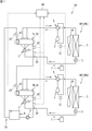
- FIG. 1 is a schematic configuration diagram of an ice making system according to the first embodiment.
- the ice making system 50 of the present embodiment uses the seawater (solution for ice making) stored in the seawater tank 8 as a raw material to continuously generate the ice slurry by the ice making machines (ice generators) 1U and 1L, and the generated ice slurry is the seawater. It is a system for returning to the tank 8.
- the ice making machines 1U and 1L of this embodiment are, for example, double-tube ice making machines.
- the ice making system 50 of the present embodiment includes a plurality (two in the illustrated example) of ice making machines 1U and 1L.
- the reference numeral "1" is used to collectively refer to a plurality of ice makers, and the reference numerals "1U” and “1L” are used to distinguish them. The same applies to the "refrigerant circuit".
- the ice slurry refers to sherbet-like ice in which fine ice is turbid in water or an aqueous solution.
- the ice slurry is also called ice slurry, slurry ice, slush ice, or liquid ice.
- the ice making system 50 of the present embodiment can continuously generate an ice slurry based on seawater. Therefore, the ice making system 50 of the present embodiment is installed in, for example, a fishing boat or a fishing port, and the ice slurry returned to the seawater tank 8 is used for keeping cold fresh fish.
- the ice making system 50 includes a refrigerant circuit 60 that performs a vapor compression refrigeration cycle, and a circulation circuit 70 that circulates the seawater to be cooled between the seawater tank 8 and the ice makers 1U and 1L. , Is provided.
- the ice making system 50 of the present embodiment includes a plurality of systems of refrigerant circuits 60U, 60L corresponding to the plurality of ice making machines 1U, 1L.
- the refrigerant circuits 60U and 60L function as a cooling mechanism that cools the seawater in the ice making machine 1.
- the ice making system 50 further includes a control device (controller) 80 that controls the operation of each device included in the ice making system 50.
- Each refrigerant circuit 60 includes an ice maker 1, a compressor 2, a heat source side heat exchanger 3, a four-way switching valve 4, a first expansion valve 5, a second expansion valve 11, a receiver 7, and the like.
- the refrigerant circuit 60 is configured by connecting each of these devices with a refrigerant pipe.
- the ice making machine 1 functions as a usage side heat exchanger of the refrigerant circuit 60.
- the compressor 2 compresses the refrigerant and circulates the refrigerant in the refrigerant circuit 60.
- the compressor 2 of the present embodiment is a variable capacity type (capacity variable type). Specifically, the compressor 2 can change the operating frequency stepwise or continuously by controlling the built-in motor with an inverter. By controlling the operating frequency of the compressor 2, it is possible to adjust the evaporation temperature of the refrigerant supplied to the ice maker 1.
- the four-way switching valve 4 is connected to the discharge side of the compressor 2.
- the four-way switching valve 4 has a function of switching the refrigerant discharged from the compressor 2 to either the heat source side heat exchanger 3 side or the ice making machine 1 side and flowing the refrigerant.
- the four-way switching valve 4 switches between ice making operation and ice melting operation.
- the first expansion valve 5 is an expansion valve on the use side and is composed of an electronic expansion valve whose opening can be adjusted according to a control signal.
- the second expansion valve 11 is an expansion valve on the heat source side and is an electronic expansion valve whose opening can be adjusted according to a control signal.
- the blower fan 10 cools the heat source side heat exchanger 3 by air.
- the blower fan 10 includes a motor whose operating speed is changed stepwise or continuously by inverter control.
- the circulation circuit 70 includes the ice making machine 1, the seawater tank 8, the pump 9, and the like.
- the circulation circuit 70 is configured by connecting each of these devices with seawater piping.
- the pump 9 sucks the seawater from the seawater tank 8 and pumps the seawater to the cooling chamber 12 of the ice maker 1.
- the ice slurry generated in the cooling chamber 12 is returned to the seawater tank 8 together with seawater by the pump pressure.
- a plurality of ice machines 1U and 1L are connected in series by seawater piping. Therefore, the seawater pumped from the pump 9 is supplied to the ice-making machine 1U on the upstream side in the flow direction of the seawater and then to the ice-making machine 1L on the downstream side, and then returned to the seawater tank 8.
- the seawater supplied to the ice makers 1U and 1L is cooled and discharged as ice slurry from the ice makers 1U and 1L.
- FIG. 2 is a side view of the ice making machine.
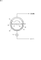
- FIG. 3 is an explanatory view schematically showing a cross section of the ice making machine.
- the ice making machine 1 of the present embodiment is configured by a double pipe type ice making machine.
- the ice making machine 1 includes an inner pipe 12 and an outer pipe 13 each formed in a cylindrical shape, and a scraping mechanism 15.
- the outer diameter of the inner tube 12 is smaller than that of the outer tube 13, and the inner tube 12 is arranged in the outer tube 13 concentrically with the outer tube 13. Further, the inner pipe 12 projects from the outer pipe 13 on both sides in the axial direction.
- the ice making machine 1 of the present embodiment is of a horizontal type, and the inner pipe 12 and the outer pipe 13 are horizontally arranged.
- the inner pipe 12 is an element through which seawater as a medium to be cooled flows and passes through.
- the inner pipe 12 constitutes a "cooling chamber” for cooling seawater.
- the “inner peripheral surface” of the inner pipe 12 constitutes the “inner surface” of the cooling chamber.
- the inner tube 12 is made of a metal material. Both ends in the axial direction of the inner pipe 12 are closed.
- a seawater inlet 16 is provided on one axial side of the inner pipe 12 (on the right side in FIG. 2). Seawater is supplied from the inflow port 16 into the inner pipe 12.
- a discharge port 17 for seawater is provided on the other end side (the left side in FIG. 2) of the inner pipe 12 in the axial direction. The seawater in the inner pipe 12 is discharged from the discharge port 17.
- a scraping mechanism 15 is arranged on the inner tube 12.
- the scraping mechanism 15 scrapes the ice generated on the inner peripheral surface of the inner pipe 12 and disperses it in the inner pipe 12.
- the scraping mechanism 15 of the present embodiment is a blade mechanism having a blade 22 for scraping.
- the blade mechanism 15 includes a blade 22, a rotary shaft 20, a support bar 21, and a drive unit 24.
- the rotating shaft 20 is rotatably supported in the inner tube 12 concentrically with the inner tube 12.
- the rotary shaft 20 projects outward from a flange 23 provided at one axial end of the inner pipe 12, and is connected to a motor 24 as a drive unit.
- the support bar 21 is made of a rod-shaped member that projects radially outward from the outer peripheral surface of the rotary shaft 20.
- the support bars 21 are provided at predetermined intervals in the axial direction of the rotary shaft 20.
- the blade 22 is fixed to the tip of the support bar 21.
- the blade 22 is made of, for example, a resin or metal strip member. The side edge of the blade 22 on the front side in the rotation direction is formed into a sharp tapered shape.
- the outer pipe 13 is provided concentrically with the inner pipe 12 on the outer side in the radial direction of the inner pipe 12.
- the outer tube 13 is made of a metal material.
- One or more (three in this embodiment) refrigerant inlets 18 are provided in the lower portion of the outer tube 13.
- One or more (two in the present embodiment) refrigerant outlets 19 are provided on the upper portion of the outer tube 13.
- the annular space 14 between the inner peripheral surface of the outer pipe 13 and the outer peripheral surface of the inner pipe 12 is a region serving as a refrigerant chamber into which a refrigerant that exchanges heat with seawater flows.
- the refrigerant supplied from the refrigerant inlet 18 passes through the annular space 14 and is discharged from the refrigerant outlet 19.
- the ice making system 50 includes a controller 80.
- the control device 80 includes a CPU and a memory.
- the memory includes RAM, ROM, flash memory and the like.
- the control device 80 realizes various controls relating to the operation of the ice making system 50 by the CPU executing the computer programs stored in the memory.
- control device 80 controls the opening degrees of the use side expansion valve 5 and the heat source side expansion valve 11.
- the controller 80 also controls the operating frequencies of the compressor 2 and the blower fan 10.
- the controller 80 also controls the operation of the drive unit 24 of the blade mechanism 15 and the pump 9.
- the controller 80 may be provided separately on the ice making machine 1 side and the heat source side heat exchanger 3 side. In this case, for example, the operation control of the heat source side expansion valve 11, the blower fan 10, and the compressor 2 is performed by the control device of the heat source side heat exchanger 3, and the operation control of the use side expansion valve 5, the drive unit 24, and the pump 9. Can be performed by the control device on the ice making machine 1 side.
- control device 80 is a detection device (second detection device) for detecting elimination of supercooling in the inner pipe 12, and a detection for detecting the presence or absence of ice nuclei in the inner pipe 12, as described later. It also serves as a component of the device (first detection device) and an adjusting device that controls the operating frequency of the compressor 2 and adjusts the evaporation temperature.
- the ice making system 50 is provided with a plurality of sensors. Specifically, as shown in FIG. 1, the refrigerant suction pipe of the compressor 2 is provided with a pressure sensor 31 for detecting the pressure of the refrigerant. At the inlet 16 of the inner pipe 12 of each ice making machine 1, a temperature sensor 32 for detecting the temperature of seawater (and ice slurry) and a concentration sensor 34 for measuring the salt concentration of seawater are provided. The outlet 17 of the inner pipe 12 of the ice making machine 1 is provided with a temperature sensor 33 for detecting the temperature of seawater (and ice slurry). The detection values of the temperature sensor 32 and the concentration sensor 34 provided at the inflow port 16 are substantially equal to the temperature and concentration of seawater flowing into the inner pipe 12. Further, the detected value of the temperature sensor 33 provided at the discharge port 17 is substantially equal to the temperature of seawater discharged from the inner pipe 12.
- the detection signals of the pressure sensor 31, the temperature sensors 32 and 33, and the concentration sensor 34 are input to the control device 80 and used for various controls.
- the detection signal of the sensor is used to control the cooling temperature (sealing temperature of the refrigerant) of seawater in the ice making machine 1.
- the refrigerant is decompressed to a predetermined low pressure by the use-side expansion valve 5 to become a gas-liquid two-phase refrigerant, and the inner pipe 12 and the outer pipe 13 constituting the ice making machine 1 are introduced from the refrigerant inlet 18 (see FIG. 2) of the ice making machine 1.
- Is supplied into the annular space (refrigerant chamber) 14 between The refrigerant supplied into the annular space 14 is heat-exchanged with the seawater flowing into the inner pipe 12 by the pump 9 and evaporated.
- the saturation temperature (evaporation temperature) of the refrigerant at this time is the cooling temperature for cooling the seawater.
- the refrigerant evaporated in the ice maker 1 is sucked into the compressor 2.
- the pump 9 sucks seawater from the tank 8 and pumps the seawater into the inner pipe 12 of each ice making machine 1.
- ice particles are generated on the inner surface of the inner pipe 12 and in the vicinity thereof.
- the ice particles thus generated are scraped off by the blade mechanism 15 and mixed with seawater in the inner pipe 12 to become ice slurry.
- the ice slurry thus produced is discharged from the discharge port 17 of the inner pipe 12 by the pump pressure and returned to the seawater tank 8.
- the ice slurry returned to the tank 8 rises in the tank 8 due to buoyancy, and becomes the state of being accumulated on the upper portion of the tank 8.
- the control device 80 switches the four-way switching valve 4 of each refrigerant circuit 60 to the state shown by the dotted line in FIG. 1 when detecting the occurrence of the ice lock or ice accumulation as described above.
- the high-temperature gas refrigerant discharged from the compressor 2 flows into the annular space 14 between the inner pipe 12 and the outer pipe 13 of the ice making machine 1 via the four-way switching valve 4 to remove the ice in the inner pipe 12. Condenses and liquefies by exchanging heat with the contained seawater. At this time, the ice in the inner tube 12 is heated by the refrigerant to be thawed.
- the liquid refrigerant discharged from the ice maker 1 passes through the utilization side expansion valve 5 in the fully opened state, and then flows into the heat source side expansion valve 11 via the receiver 7.
- the liquid refrigerant is decompressed by the heat source side expansion valve 11, evaporated in the heat source side heat exchanger 3, and sucked into the compressor 2.
- the easiness of ice rock differs depending on whether or not there are ice particles called ice nuclei in the inner tube 12. If there is no ice nuclei in the inner tube 12, the seawater is in a supercooled state at a temperature lower than the freezing temperature as described above, and the supercooled state is eliminated, so that ice lock is likely to occur. On the other hand, if ice nuclei are present in the inner pipe 12, the seawater is not supercooled and is cooled to the freezing temperature to generate ice.
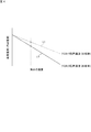
- FIG. 4 is a graph showing the lower limit of the evaporation temperature (cooling temperature) that does not cause ice lock (ice lock limit temperature) in relation to the concentration of seawater.
- the ice lock limit temperature when there is no ice nucleus in the inner tube 12 is shown by L1
- the ice lock limit temperature when there is an ice nucleus is shown by L2.
- the ice rock limit temperature is higher in the former than in the latter, regardless of the concentration of seawater, depending on whether or not there is an ice nucleus in the inner pipe 12. Therefore, when ice nuclei are present in the inner pipe 12, ice rock is less likely to occur, and the evaporation temperature can be further lowered to promote the production of ice. If there are no ice nuclei in the inner tube 12, ice vapor is more likely to occur unless the evaporation temperature is higher than when ice nuclei are present. It takes.
- the ice making system 50 of the present embodiment detects the presence or absence of ice nuclei in the inner pipe 12 of each ice making machine 1, and when there is no ice nuclei, raises the evaporation temperature to prevent the occurrence of ice lock. If ice nuclei are present, the evaporation temperature is lowered to promote the production of ice, and the ice making system 50 as a whole is configured to efficiently make ice.
- the controller 80 performs the two-stage processing shown in the following (a) and (b) during the ice making operation.
- FIG. 5 is a graph showing changes in the temperature of seawater at the inlet and outlet of the inner pipe.
- the temperature T2 at the outlet 17 of the inner pipe 12 gradually decreases with the passage of time, and at time t1, the freezing temperature is exceeded and the supercooled state is reached.
- the temperature T1 at the inflow port 16 of the inner pipe 12 is gradually lowered after the temperature T2 at the exhaust port 17. Further, the temperature T2 at the outlet 17 of the inner pipe 12 rises to the freezing temperature at time t2 due to the elimination of the supercooling. As a result, generation of ice is started in the inner pipe 12.
- the control device 80 of the present embodiment detects that the supercooling has been reliably eliminated, so that the supercooling is eliminated at time t3 when the seawater rises to the freezing temperature and stabilizes. I try to judge.
- the temperature T1 of seawater gradually approaches the freezing temperature and stabilizes. Therefore, in the process (b), the control device 80 determines that the seawater reaches the freezing temperature and the ice nuclei are present at the time t5 when the temperature stabilizes.
- the detection of subcooling elimination in (a) above is performed by the control device 80 determining whether the following conditions 1 to 3 are satisfied.
- (Condition 1) The operation time of the ice making system 50 has passed a predetermined time or longer.
- (Condition 2) The seawater temperature at the outlet 17 of each inner pipe 12 is less than 0° C. for a certain period of time (Condition 3)
- Each inner pipe The amount of change in seawater temperature at outlets 12 of 12 is less than a predetermined value for a certain period of time.
- the presence/absence of ice nuclei in (b) above is detected by the control device 80 by determining whether the following conditions 4 to 7 are satisfied.
- Condition 4 The seawater temperature at the inlet 16 of each inner pipe 12 is less than 0° C. for a certain period of time (Condition 5)
- the amount of change in the seawater temperature at the inlet 16 of each inner pipe 12 is less than a predetermined value for a certain period of time (Condition 6)
- the temperature difference of the seawater between the inlet 16 and the outlet 17 of each inner pipe 12 is less than a predetermined value for a certain period of time (Condition 7)
- the supercooling at the outlet 17 of each inner pipe 12 is eliminated. Have passed a certain time since
- these temperature sensors 32 and 33 are one of a detection device (second detection device) for detecting elimination of supercooling or a detection device (first detection device) for detecting the presence or absence of ice nuclei. It becomes a component.
- the control device 80 determines whether or not a predetermined time or more has elapsed from the start of the operation of the ice making system 50 as "condition 1" for detecting the elimination of supercooling in (a) above. This is because the temperature of seawater in the inner pipe 12 does not decrease until a certain amount of time elapses, and the supercooling does not disappear after the supercooled state.
- the operating time of the condition 1 can be set to, for example, 20 minutes.
- condition 2 for detecting the elimination of supercooling, the control device 80 determines whether or not the temperature T2 of the seawater at the outlet 17 of each inner pipe 12 is lower than 0° C. for a certain period of time. After the start of operation, the temperature of seawater T2 may temporarily become 0°C in the process of decreasing, and it is always less than 0°C from the supercooled state until supercooling is eliminated and the freezing temperature is reached. Because.
- the condition 2 can be set as a condition that the temperature is kept below 0° C. for 15 minutes, for example, as the constant time.
- the control device 80 determines whether or not the amount of change in the temperature T2 of the seawater at the outlet 17 of the inner pipe 12 is less than a predetermined value for a certain period of time. As shown in FIG. 5, when the temperature T2 rises from the supercooled state to the freezing temperature at the time t2, it can be said that the supercooled state is canceled for the time being. However, erroneous detection due to a failure of the temperature sensor 33 or other factors is also conceivable. Therefore, in the present embodiment, the condition 3 is set so that it can be detected that the supercooling has been reliably eliminated.
- Expression (1) is conditioned on the condition that the amount of change between the current temperature T2 and the temperature T2′ before a predetermined time is smaller than the predetermined value ⁇ continues for a predetermined time.
- the predetermined value ⁇ can be 0.4° C., for example. Therefore, the equation (1) is on condition that the temperature T2 of the seawater is stable with almost no change.
- the controller 80 detects that the supercooling has been eliminated at the outlet 17 of the inner pipe 12 when the above conditions 1 to 3 are satisfied.
- the control device 80 keeps the temperature T1 at the inlet 16 of each inner tube 12 below 0° C. for a certain time (for example, 15 minutes). Determine that there is. This is because when the temperature of seawater at the inflow port 16 is 0° C. or higher, it is extremely unlikely that ice nuclei are present at the inflow port 16.
- the control device 80 determines that the amount of change in the seawater temperature T1 at the inlet 16 of each inner pipe 12 is less than a predetermined value for a certain period of time. As shown in FIG. 5, the temperature T1 of the seawater at the inflow port 16 falls below 0° C. at time t4, and then decreases to reach the freezing temperature. Then, if the state at the freezing temperature continues for a certain period of time, it can be determined that ice nuclei are present at the inflow port 16 and ice is being produced.
- the equation (2) indicates that the amount of change between the current temperature T1 and the temperature T1' before the predetermined time is smaller than the predetermined value ⁇ .
- the predetermined value ⁇ can be set to 0.4° C., for example. Therefore, the equation (2) is conditioned on the fact that the temperature T1 of the seawater is stable with almost no change.
- the control device 80 determines that the temperature difference of the refrigerant between the inlet 16 and the outlet 17 of each inner tube 12 is less than a predetermined value for a certain period of time. .. As shown in FIG. 5, when the seawater temperature T1 at the inflow port 16 stabilizes near the freezing temperature, the temperature difference from the seawater temperature T2 at the discharge port 17 becomes small. Therefore, under this condition 5, the temperature T1 of the seawater at the inlet 16 and the temperature T2 of the seawater at the outlet 17 are compared, and the state represented by the following equation (3) is maintained for a certain time ( ⁇ tb in FIG. 5, for example, 15 For a minute), determine whether to continue.
- Expression (3) indicates that the difference between the temperature T1 of the inlet 16 and the temperature T2 of the outlet 17 is smaller than the predetermined value ⁇ .
- the predetermined value ⁇ can be set to 0.4° C., for example. Therefore, the equation (3) is conditional on the temperature of the entire seawater in the inner pipe 12 being substantially constant.
- condition 7 for detecting the presence or absence of ice nuclei
- the control device 80 indicates that a certain period of time (for example, 15 minutes) has elapsed since the supercooling was eliminated at the outlet 17 of each inner tube 12. Determine. The detection that the supercooling has been eliminated at the outlet 17 of the inner pipe 12 is performed by the determination of the above-mentioned conditions 1 to 3.
- the control device 80 detects the presence of ice nuclei at the inlet 16 of the inner pipe 12 when the above conditions 4 to 7 are satisfied.
- control device 80 When the control device 80 detects the presence of ice nuclei in the inlet 16 of the inner pipe 12 of the ice making machine 1 by the above processing, it controls the compressor 2 of the refrigerant circuit 60 in which the ice making machine 1 is provided, Adjust the evaporation temperature of. Specifically, the control device 80 sets the target evaporation temperature from the concentration of seawater flowing into the ice making machine 1 (concentration detected by the concentration sensor 34) with the ice lock limit temperature L2 shown in FIG. 4 as the lower limit.
- the control device 80 controls the operating frequency of the compressor 2 in the refrigerant circuit 60 provided with the ice making machine 1 so that the evaporation temperature of the refrigerant becomes the target evaporation temperature.
- the control device 80 controls the operating frequency of the compressor 2 so that the low pressure detected by the pressure sensor 31 becomes the target evaporation pressure corresponding to the target evaporation temperature. Thereby, the production of ice can be promoted, and ice can be efficiently produced.
- the ice making system 50 of the present embodiment includes a plurality of ice making machines 1U and 1L and a plurality of refrigerant circuits 60U and 60L provided corresponding to the ice making machines 1U and 1L, and each of the ice making machines 1U and 1L.
- the presence or absence of ice nuclei is detected, and the evaporation temperature of the refrigerant in the refrigerant circuits 60U and 60L corresponding to the ice making machines 1U and 1L is controlled based on the detection result.
- the temperature of the seawater flowing into the inner pipe 12 from the inflow port 16 gradually decreases as the seawater flows toward the outflow port 17.
- the temperature decreases, the supercooled state starts from the side of the discharge port 17 having a lower temperature, the supercooling is eliminated from the side of the discharge port 17 and ice making starts.
- the upstream ice maker 1U when supercooling is eliminated and ice nuclei are generated on the discharge port 17 side, the ice nuclei are discharged from the discharge port 17 and immediately the inner pipe 12 of the downstream ice maker 1L. Flow into. Therefore, in the downstream ice making machine 1L, ice nuclei are present at the inflow port 16 of the inner pipe 12 relatively early.
- the ice nuclei generated on the discharge port 17 side of the downstream ice making machine 1L are returned to the tank 8 after being discharged from the discharge port 17, so that the ice nuclei of the upstream ice making machine 1U are then discharged from the tank 8. It takes time for the ice nuclei to flow into the inner tube 12. Therefore, normally, the ice making machine 1 on the downstream side is controlled so that the ice nuclei are first present in the inflow port 16 of the inner pipe 12 and the evaporation temperature of the refrigerant supplied to the ice making machine 1 is lowered. Will be promoted.
- FIG. 6 is a schematic configuration diagram of an ice making system according to the second embodiment.
- the ice making system 50 of the present embodiment is similar to the first embodiment in that it is provided with a plurality of ice making machines 1, but is provided with a plurality of refrigerant circuits 60 corresponding to each of the plurality of ice making machines 1. Instead, a single-system refrigerant circuit 60 corresponding to the plurality of ice makers 1 is provided.
- this refrigerant circuit 60 a plurality of ice making machines 1 are connected in parallel, and expansion valves 5U and 5L are provided corresponding to each ice making machine 1.
- a flow rate adjusting valve 35 for adjusting the flow rate of the gas refrigerant discharged from the ice making machine 1U is provided in the refrigerant pipe between the upstream ice making machine 1U and the four-way switching valve 4.
- the control device 80 of the present embodiment detects the elimination of supercooling at the outlet 17 of the inner pipe 12 of each ice making machine 1 and detects the ice nuclei at the inlet 16 of the inner pipe 12. Presence and absence is detected.
- the control device 80 controls the operating frequency of the compressor 2 to reduce the evaporation temperature of the refrigerant.
- the control device 80 controls the flow rate adjusting valve 35 in the closing direction so as to reduce the flow rate of the gas refrigerant discharged from the ice making machine 1U on the upstream side, and the evaporation pressure of the refrigerant in the ice making machine 1U. Is adjusted so that the evaporation temperature does not decrease. As a result, the ice making machine 1U on the upstream side can perform the ice making operation at a higher evaporation temperature that does not generate ice lock.
- the ice making system 50 of the second embodiment may include a flow rate adjusting valve for adjusting the flow rate of the gas refrigerant discharged from the ice making machine 1L on the downstream side, and the ice making machine on the downstream side by the flow rate adjusting valve. You may adjust the evaporation temperature of the refrigerant supplied to 1L.
- the conditions 4 to 7 are determined in order to detect the presence or absence of ice nuclei at the inflow port 16 of the inner pipe 12 of the ice making machine 1. However, only one or more of these conditions are determined. It can also be adopted. For example, only conditions 4 and 5 can be adopted to detect the presence or absence of ice nuclei. Further, in addition to the conditions 4 and 5, the condition 6 or the condition 7 can be adopted. Further, in the above-described embodiment, the conditions 1 to 3 are determined in order to detect the elimination of the supercooling at the outlet 17 of the inner pipe 12 of the ice making machine 1. However, for example, only the conditions 1 and 2 are determined. You may make a distinction.
- the ice machine 1 is a “vertical” or “tilted” double-tube ice machine. May be.
- the ice making system 50 including the two ice making machines 1 is illustrated, but the number of the ice making machines 1 may be one, or may be three or more.
- the ice making system 50 in which the solution to be cooled is “sea water” has been exemplified, but the object to be cooled is not limited to sea water and may be another solution such as ethylene glycol.
- the scraping mechanism 15 of the above-described embodiment is a blade mechanism including the blade 22 that rotates around the center of the inner tube 12, another type of scraping mechanism, for example, an auger-type scraping mechanism having a screw. May be
- the predetermined values ⁇ , ⁇ , ⁇ used in the equations (1) to (3) for detecting the elimination of supercooling or detecting the presence or absence of ice nuclei are set to 0.4° C.
- the present invention is not limited to this, and can be changed as appropriate.
- the ice-making system 50 of each of the above-described embodiments has a circulation circuit 70 for circulating a solution (seawater) for ice-making, a solution inlet port 16 and an outlet port 17 and a cooling chamber for flowing the solution inside ( Inner pipe) 12 and a scraping mechanism (blade mechanism) 15 for scraping ice generated on the inner surface of the cooling chamber 12, and the ice making machine 1 provided in the circulation circuit 70 and the seawater in the cooling chamber 12
- An adjusting device (control device 80) for adjusting the cooling temperature of the seawater (evaporating temperature of the refrigerant) according to the above.
- the first detection device detects the presence or absence of ice nuclei at the inflow port 16 of the cooling chamber 12, and the adjusting device controls the cooling mechanism 60 according to the detection result to control the cooling temperature of the solution. adjust. Therefore, when the first detection device detects that there is an ice nucleus flowing into the cooling chamber 12, it becomes possible to further reduce the cooling temperature within a range where the ice lock is not generated, thereby enhancing the ice making capacity and efficiently. Can make ice.
- a plurality of ice machines 1U and 1L are provided in series in the circulation circuit 70, and the first detection device is the ice core at the inlet 16 of the cooling chamber 12 of each ice machine 1U and 1L.
- the adjustment device controls the cooling mechanism 60 according to the detection result of the first detection device to individually adjust the cooling temperature of the solution in the cooling chamber 12 of each ice making machine 1U, 1L. .. Therefore, the presence or absence of ice nuclei flowing into the cooling chamber 12 of each ice making machine 1U, 1L is detected, the cooling temperature is adjusted for each ice making machine 1U, 1L, and the ice making capacity of each ice making machine 1U, 1L is efficiently achieved. Can be increased.
- the cooling mechanism 60 includes a plurality of systems of refrigerant circuits 60U and 60L corresponding to the plurality of ice making machines 1U and 1L, and each of the refrigerant circuits 60U and 60L is a vapor compression type.
- the refrigerating cycle supplies a refrigerant individually to the corresponding ice making machines 1U, 1L, and each refrigerant circuit 60U, 60L is provided with a variable displacement compressor 2 controlled by an adjusting device.
- the adjusting device adjusts the evaporation temperature (that is, the cooling temperature) of the refrigerant supplied to the ice makers 1U and 1L by controlling the capacity of the compressor 2 of the refrigerant circuits 60U and 60L. be able to.
- the cooling mechanism 60 includes the one-system refrigerant circuit 60 that connects the plurality of ice making machines 1U and 1L in parallel, and the plurality of ice making machines 1U and 1U are provided by the vapor compression refrigeration cycle.
- the refrigerant circuit 60 supplies a refrigerant to each of the 1L, and the refrigerant circuit 60 controls the flow rate of the gaseous refrigerant that is vaporized by passing through at least the upstream ice making machine 1U in the solution flow direction, which is controlled by the adjusting device;
- the compressor 2 for sucking the gaseous refrigerant that has passed through the flow rate adjusting valve 35.
- the adjusting device controls the flow rate adjusting valve 35 to adjust the flow rate of the gaseous refrigerant passing through at least the upstream ice making machine 1U, and the evaporation temperature of the refrigerant supplied to the ice making machine 1U ( That is, the cooling temperature) can be adjusted.
- the first detection device determines that the solution temperature at the inlet 16 of the cooling chamber 12 is less than 0 degrees and the temperature change amount of the solution is less than the predetermined value for a certain period of time. As a condition. Therefore, the presence or absence of ice nuclei flowing into the cooling chamber 12 can be detected by the first detection device.
- the first detection device further requires that the temperature difference of the solution between the inlet 16 and the outlet 17 of the cooling chamber 12 is less than a predetermined value for a certain period of time. And Therefore, the presence or absence of ice nuclei flowing into the cooling chamber 12 can be more accurately detected by the first detection device.
- the ice making system 50 includes the second detection device (the temperature sensor 33, the control device 80) that detects the elimination of the supercooling at the outlet 17 of the cooling chamber 12, and the first detection device is Further, the condition that ice nuclei exist is that the elimination of supercooling is detected by the second detection device. According to this configuration, the presence or absence of ice nuclei flowing into the cooling chamber 12 can be more accurately detected by using the second detection device together.
- the second detection device eliminates overcooling when the solution temperature at the outlet 17 of the cooling chamber 12 is less than 0 degrees and the temperature change amount of the solution is less than a predetermined value for a certain period of time. The condition of. Therefore, the second detection device can detect the elimination of supercooling at the outlet 17 of the cooling chamber 12.
- Ice maker 2 Compressor 12: Inner pipe (cooling chamber) 15: scraping mechanism 16: inflow port 17: discharge port 32: temperature sensor 33: temperature sensor 35: flow rate adjusting valve 50: ice making system 60, 60L, 60U: refrigerant circuit (cooling mechanism) 70: Circulation circuit 80: Control device (detection device, supply device)
Landscapes
- Engineering & Computer Science (AREA)
- Physics & Mathematics (AREA)
- Mechanical Engineering (AREA)
- Thermal Sciences (AREA)
- General Engineering & Computer Science (AREA)
- Production, Working, Storing, Or Distribution Of Ice (AREA)
Abstract
Ce système de fabrication de glace comprend : un circuit de circulation (70) pour faire circuler une solution de fabrication de glace; une machine de fabrication de glace (1) qui comprend une chambre de refroidissement (12) qui a un orifice d'entrée (16) et un orifice de sortie (17) pour la solution et amène la solution à s'écouler à l'intérieur de celle-ci, et un mécanisme de raclage (15) pour racler la glace générée sur la surface interne de la chambre de refroidissement (12), et qui est disposé dans le circuit de circulation (70); un mécanisme de refroidissement (60) pour refroidir la solution à l'intérieur de la chambre de refroidissement (12); un premier dispositif de détection pour détecter s'il existe un noyau de glace dans l'orifice d'entrée (16) de la chambre de refroidissement (12); et un dispositif de réglage pour ajuster la température de refroidissement de la solution en fonction du résultat de détection du premier dispositif de détection.
Priority Applications (3)
| Application Number | Priority Date | Filing Date | Title |
|---|---|---|---|
| EP19902432.4A EP3904790B1 (fr) | 2018-12-28 | 2019-09-26 | Système de fabrication de glace et procédé de fabrication de glace |
| CN201980085508.7A CN113227680B (zh) | 2018-12-28 | 2019-09-26 | 制冰系统以及制冰方法 |
| US17/416,452 US11300343B2 (en) | 2018-12-28 | 2019-09-26 | Icemaking system and icemaking method |
Applications Claiming Priority (2)
| Application Number | Priority Date | Filing Date | Title |
|---|---|---|---|
| JP2018-246580 | 2018-12-28 | ||
| JP2018246580A JP6627959B1 (ja) | 2018-12-28 | 2018-12-28 | 製氷システム、及び、製氷方法 |
Publications (1)
| Publication Number | Publication Date |
|---|---|
| WO2020137055A1 true WO2020137055A1 (fr) | 2020-07-02 |
Family
ID=69101111
Family Applications (1)
| Application Number | Title | Priority Date | Filing Date |
|---|---|---|---|
| PCT/JP2019/037743 Ceased WO2020137055A1 (fr) | 2018-12-28 | 2019-09-26 | Système de fabrication de glace et procédé de fabrication de glace |
Country Status (5)
| Country | Link |
|---|---|
| US (1) | US11300343B2 (fr) |
| EP (1) | EP3904790B1 (fr) |
| JP (1) | JP6627959B1 (fr) |
| CN (1) | CN113227680B (fr) |
| WO (1) | WO2020137055A1 (fr) |
Families Citing this family (5)
| Publication number | Priority date | Publication date | Assignee | Title |
|---|---|---|---|---|
| CN110986443B (zh) * | 2020-01-19 | 2024-03-08 | 重庆大学 | 联合制冰机的热源塔热泵系统 |
| JP7607927B2 (ja) * | 2021-08-02 | 2025-01-06 | FrostiX株式会社 | 製氷装置及び製氷方法 |
| US20240255202A1 (en) * | 2021-07-20 | 2024-08-01 | Blanctec International Co., Ltd. | Ice-making device and ice-making method |
| CN115524032A (zh) * | 2022-10-21 | 2022-12-27 | 新东海(佛山)五金电器制造有限公司 | 一种半导体制冰机制冰状态识别方法 |
| CZ2022492A3 (cs) * | 2022-11-22 | 2023-11-15 | KovalĂk Electrotechnics s.r.o. | Zapojení tepelných čerpadel a způsob řízení tepelných čerpadel tohoto zapojení |
Citations (6)
| Publication number | Priority date | Publication date | Assignee | Title |
|---|---|---|---|---|
| JPS61243266A (ja) * | 1985-04-19 | 1986-10-29 | 三洋電機株式会社 | 製氷機の保護装置 |
| JPH03204575A (ja) | 1989-12-28 | 1991-09-06 | Daikin Ind Ltd | 製氷装置 |
| JPH04263763A (ja) * | 1990-12-29 | 1992-09-18 | Daikin Ind Ltd | 製氷装置 |
| JPH09264642A (ja) * | 1996-03-28 | 1997-10-07 | Kubota Corp | 過冷却式製氷装置 |
| JPH1047714A (ja) * | 1996-05-30 | 1998-02-20 | Daikin Ind Ltd | 氷蓄熱装置の凍結防止装置及び凍結防止設計方法 |
| JP2002323278A (ja) * | 2001-04-24 | 2002-11-08 | Hoshizaki Electric Co Ltd | オーガ式製氷機の保護装置 |
Family Cites Families (8)
| Publication number | Priority date | Publication date | Assignee | Title |
|---|---|---|---|---|
| US3650121A (en) * | 1969-12-22 | 1972-03-21 | Borg Warner | Icemaker protection system |
| JP3828834B2 (ja) * | 2001-07-09 | 2006-10-04 | ホシザキ電機株式会社 | 製氷機 |
| JP4383698B2 (ja) | 2001-11-07 | 2009-12-16 | 関西電力株式会社 | スラリー氷の製氷方法とその製氷装置 |
| CN101782306A (zh) * | 2008-12-31 | 2010-07-21 | 曼尼托沃食品服务有限公司 | 带有进水温度检测的制冰机及其控制方法 |
| US9879895B2 (en) | 2013-10-09 | 2018-01-30 | Haier Us Appliance Solutions, Inc. | Ice maker assembly for a refrigerator appliance and a method for operating the same |
| JP6200482B2 (ja) | 2015-11-30 | 2017-09-20 | ダイキン工業株式会社 | 製氷装置 |
| US10598419B2 (en) * | 2017-05-19 | 2020-03-24 | Zhejiang Ocean University | Seawater fluidized ice manufacturing equipment and method |
| CN108645084B (zh) * | 2018-05-30 | 2024-05-14 | 佛山市顺德区美的饮水机制造有限公司 | 制冰模组和嵌入式净饮机 |
-
2018
- 2018-12-28 JP JP2018246580A patent/JP6627959B1/ja active Active
-
2019
- 2019-09-26 US US17/416,452 patent/US11300343B2/en active Active
- 2019-09-26 EP EP19902432.4A patent/EP3904790B1/fr active Active
- 2019-09-26 WO PCT/JP2019/037743 patent/WO2020137055A1/fr not_active Ceased
- 2019-09-26 CN CN201980085508.7A patent/CN113227680B/zh active Active
Patent Citations (6)
| Publication number | Priority date | Publication date | Assignee | Title |
|---|---|---|---|---|
| JPS61243266A (ja) * | 1985-04-19 | 1986-10-29 | 三洋電機株式会社 | 製氷機の保護装置 |
| JPH03204575A (ja) | 1989-12-28 | 1991-09-06 | Daikin Ind Ltd | 製氷装置 |
| JPH04263763A (ja) * | 1990-12-29 | 1992-09-18 | Daikin Ind Ltd | 製氷装置 |
| JPH09264642A (ja) * | 1996-03-28 | 1997-10-07 | Kubota Corp | 過冷却式製氷装置 |
| JPH1047714A (ja) * | 1996-05-30 | 1998-02-20 | Daikin Ind Ltd | 氷蓄熱装置の凍結防止装置及び凍結防止設計方法 |
| JP2002323278A (ja) * | 2001-04-24 | 2002-11-08 | Hoshizaki Electric Co Ltd | オーガ式製氷機の保護装置 |
Also Published As
| Publication number | Publication date |
|---|---|
| US11300343B2 (en) | 2022-04-12 |
| CN113227680A (zh) | 2021-08-06 |
| JP2020106237A (ja) | 2020-07-09 |
| US20220042733A1 (en) | 2022-02-10 |
| EP3904790A4 (fr) | 2022-03-02 |
| EP3904790B1 (fr) | 2023-08-30 |
| CN113227680B (zh) | 2022-08-05 |
| EP3904790A1 (fr) | 2021-11-03 |
| JP6627959B1 (ja) | 2020-01-08 |
Similar Documents
| Publication | Publication Date | Title |
|---|---|---|
| WO2020137055A1 (fr) | Système de fabrication de glace et procédé de fabrication de glace | |
| JP6540872B1 (ja) | 製氷システム | |
| CN111602016B (zh) | 制冰系统 | |
| JP6234507B2 (ja) | 冷凍装置及び冷凍サイクル装置 | |
| CN111602015B (zh) | 制冰系统以及用于该制冰系统的蒸发温度的控制方法 | |
| JP5956326B2 (ja) | 冷凍装置及び冷凍サイクル装置 | |
| JP6645565B2 (ja) | 製氷システム | |
| JP2021162250A (ja) | ヒートポンプサイクル装置 | |
| JP6614250B2 (ja) | 製氷システム | |
| JP7089153B2 (ja) | 製氷システム | |
| JP6760361B2 (ja) | 製氷機の運転制御方法 | |
| KR20190079057A (ko) | 얼음 생성 장치 및 이의 제어 방법 | |
| JP2020026923A (ja) | 製氷システム | |
| JP2020026924A (ja) | 製氷機の運転制御方法 |
Legal Events
| Date | Code | Title | Description |
|---|---|---|---|
| 121 | Ep: the epo has been informed by wipo that ep was designated in this application |
Ref document number: 19902432 Country of ref document: EP Kind code of ref document: A1 |
|
| NENP | Non-entry into the national phase |
Ref country code: DE |
|
| ENP | Entry into the national phase |
Ref document number: 2019902432 Country of ref document: EP Effective date: 20210728 |
|
| ENP | Entry into the national phase |
Ref document number: 2019902432 Country of ref document: EP Effective date: 20210728 |