WO2020137064A1 - Dispositif de connexion - Google Patents
Dispositif de connexion Download PDFInfo
- Publication number
- WO2020137064A1 WO2020137064A1 PCT/JP2019/038580 JP2019038580W WO2020137064A1 WO 2020137064 A1 WO2020137064 A1 WO 2020137064A1 JP 2019038580 W JP2019038580 W JP 2019038580W WO 2020137064 A1 WO2020137064 A1 WO 2020137064A1
- Authority
- WO
- WIPO (PCT)
- Prior art keywords
- held
- portions
- connection device
- extension
- rear direction
- Prior art date
- Legal status (The legal status is an assumption and is not a legal conclusion. Google has not performed a legal analysis and makes no representation as to the accuracy of the status listed.)
- Ceased
Links
Images








Classifications
-
- H—ELECTRICITY
- H01—ELECTRIC ELEMENTS
- H01R—ELECTRICALLY-CONDUCTIVE CONNECTIONS; STRUCTURAL ASSOCIATIONS OF A PLURALITY OF MUTUALLY-INSULATED ELECTRICAL CONNECTING ELEMENTS; COUPLING DEVICES; CURRENT COLLECTORS
- H01R13/00—Details of coupling devices of the kinds covered by groups H01R12/70 or H01R24/00 - H01R33/00
- H01R13/46—Bases; Cases
- H01R13/52—Dustproof, splashproof, drip-proof, waterproof, or flameproof cases
- H01R13/5213—Covers
-
- H—ELECTRICITY
- H01—ELECTRIC ELEMENTS
- H01R—ELECTRICALLY-CONDUCTIVE CONNECTIONS; STRUCTURAL ASSOCIATIONS OF A PLURALITY OF MUTUALLY-INSULATED ELECTRICAL CONNECTING ELEMENTS; COUPLING DEVICES; CURRENT COLLECTORS
- H01R13/00—Details of coupling devices of the kinds covered by groups H01R12/70 or H01R24/00 - H01R33/00
- H01R13/62—Means for facilitating engagement or disengagement of coupling parts or for holding them in engagement
- H01R13/639—Additional means for holding or locking coupling parts together, after engagement, e.g. separate keylock, retainer strap
-
- H—ELECTRICITY
- H01—ELECTRIC ELEMENTS
- H01R—ELECTRICALLY-CONDUCTIVE CONNECTIONS; STRUCTURAL ASSOCIATIONS OF A PLURALITY OF MUTUALLY-INSULATED ELECTRICAL CONNECTING ELEMENTS; COUPLING DEVICES; CURRENT COLLECTORS
- H01R31/00—Coupling parts supported only by co-operation with counterpart
- H01R31/06—Intermediate parts for linking two coupling parts, e.g. adapter
-
- H—ELECTRICITY
- H01—ELECTRIC ELEMENTS
- H01R—ELECTRICALLY-CONDUCTIVE CONNECTIONS; STRUCTURAL ASSOCIATIONS OF A PLURALITY OF MUTUALLY-INSULATED ELECTRICAL CONNECTING ELEMENTS; COUPLING DEVICES; CURRENT COLLECTORS
- H01R13/00—Details of coupling devices of the kinds covered by groups H01R12/70 or H01R24/00 - H01R33/00
- H01R13/46—Bases; Cases
- H01R13/52—Dustproof, splashproof, drip-proof, waterproof, or flameproof cases
- H01R13/5205—Sealing means between cable and housing, e.g. grommet
-
- H—ELECTRICITY
- H01—ELECTRIC ELEMENTS
- H01R—ELECTRICALLY-CONDUCTIVE CONNECTIONS; STRUCTURAL ASSOCIATIONS OF A PLURALITY OF MUTUALLY-INSULATED ELECTRICAL CONNECTING ELEMENTS; COUPLING DEVICES; CURRENT COLLECTORS
- H01R2107/00—Four or more poles
-
- H—ELECTRICITY
- H01—ELECTRIC ELEMENTS
- H01R—ELECTRICALLY-CONDUCTIVE CONNECTIONS; STRUCTURAL ASSOCIATIONS OF A PLURALITY OF MUTUALLY-INSULATED ELECTRICAL CONNECTING ELEMENTS; COUPLING DEVICES; CURRENT COLLECTORS
- H01R24/00—Two-part coupling devices, or either of their cooperating parts, characterised by their overall structure
- H01R24/28—Coupling parts carrying pins, blades or analogous contacts and secured only to wire or cable
-
- H—ELECTRICITY
- H01—ELECTRIC ELEMENTS
- H01R—ELECTRICALLY-CONDUCTIVE CONNECTIONS; STRUCTURAL ASSOCIATIONS OF A PLURALITY OF MUTUALLY-INSULATED ELECTRICAL CONNECTING ELEMENTS; COUPLING DEVICES; CURRENT COLLECTORS
- H01R29/00—Coupling parts for selective co-operation with a counterpart in different ways to establish different circuits, e.g. for voltage selection, for series-parallel selection, programmable connectors
Definitions
- the present invention relates to a connecting device used for conducting predetermined ones of a plurality of counterpart terminals.
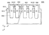
- Patent Document 1 discloses this type of connection device 900.
- the connection device 900 of Patent Document 1 includes a holding member 910 and a conductive member 950.
- the holding member 910 has a holding portion 912.
- the holding portion 912 is provided with a plurality of exposure holes 9122.
- the exposure hole 9122 penetrates a part of the holding portion 912 in the Z direction.
- the conductive member 950 includes a plurality of held parts 952, a plurality of contact parts 954, and a plurality of connecting parts 956.
- the held portion 952 is held by the holding portion 912.
- the held parts 952 are arranged in the Y direction.
- the contact portion 954 is a portion that directly contacts a counterpart terminal (not shown).
- the contact portions 954 extend from the held portion 952 in the +X direction.
- Each of the connecting portions 956 connects the held portions 952 that are adjacent to each other in the Y direction.
- the connecting portions 956 correspond to the exposed holes 9122, respectively.
- Each of the connecting portions 956 is partially exposed in the corresponding exposure hole 9122.
- the press pin 970 and the receiving jig 980 are used to set the specific connecting portion 956. Are partially removed through the corresponding exposed holes 9122.
- connection device 900 of Patent Document 1 a special tool such as the press pin 970 and the receiving jig 980 is required to remove the portion of the conductive member 950 that is desired to be made non-conductive.
- an object of the present invention is to provide a connecting device provided with a conductive member that allows a user to adjust a portion where discontinuity of conduction is to be made without using a special tool.
- One aspect of the present invention provides a connecting device including a holding member and a conductive member.
- the conductive member is held by the holding member.
- the holding member has a holding portion.
- the conductive member has a plurality of held parts, a plurality of contact parts, a plurality of extension parts, and a plurality of connecting parts.
- the held portions are held by the holding portion and are arranged in the left-right direction.
- the contact portions correspond to the held portions, respectively.
- Each of the contact portions is located in front of the corresponding held portion in the front-rear direction orthogonal to the left-right direction.
- Each of the plurality of extension portions extends rearward in the front-rear direction from any of the held portions and projects rearward of the holding portion in the front-rear direction.
- the plurality of extension portions are located apart from each other in the left-right direction.
- the plurality of connecting portions are located apart from each other in the left-right direction.
- the plurality of connecting portions are located behind the plurality of extending portions in the front-rear direction.
- Each of the connecting portions connects the two extending portions to each other.
- the two held parts that are adjacent to each other in the left-right direction are connected to the two extended parts, respectively.
- each extension portion extends rearward from any of the held portions and projects rearward of the holding portion of the holding member.
- the connecting portions are located apart from each other in the left-right direction.
- Each of the connecting parts connects the two extension parts to each other.
- the two held portions that are adjacent to each other in the left-right direction are connected to the two extended portions, respectively.
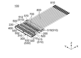
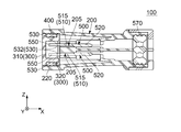
- FIG. 2 is a partially cutaway perspective sectional view showing the connection device of FIG. 1.
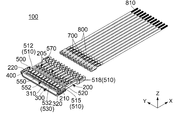
- FIG. 4 is another partially cutaway perspective sectional view showing the connection device of FIG. 3.
- the contacted part is not in contact with the contact part.
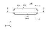
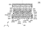
- FIG. 7 is a cross-sectional view showing the connection device of FIG. 6 taken along line AA.
- FIG. 13 is a partially cutaway perspective sectional view showing the connection device of FIG. 12. Here, a cap is attached to the surrounding portion of the holding member.
- FIG. 14 is another partially cutaway perspective sectional view showing the connection device of FIG. 13. Here, the contacted part is not in contact with the contact part.
- FIG. 13 is a perspective view showing a conductive member included in the connection device of FIG. 12. It is a perspective view which shows the connection device by the 2nd Embodiment of this invention. Here, the first connector and the second connector are not connected.
- FIG. 17 is a partially cutaway perspective sectional view showing the connection device of FIG. 16.
- FIG. 17 is a perspective view showing a first connector included in the connection device of FIG. 16.
- a cap is attached to the surrounding portion of the first holding member.
- FIG. 19 is another perspective view showing the first connector of FIG. 18.
- the cap is removed from the enclosure of the first holding member.
- FIG. 22 shows the modification of the connection device of FIG.
- FIG. 22 is another cross-sectional view showing the connection device of FIG. 21.
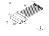
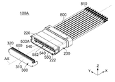
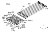
- the connection device 100 As shown in FIG. 3, the connection device 100 according to the first embodiment of the present invention includes a holding member 200, a conductive member 500, a contacted portion 700, and a plurality of cables 800.
- the conductive member 500 is held by the holding member 200.
- holding member 200 of the present embodiment is made of an insulating member.
- the holding member 200 has a plurality of accommodation holes 205 and an enclosing portion 220.
- each of the accommodation holes 205 of the present embodiment penetrates the holding member 200 in the front-back direction.
- the accommodation hole 205 is located in front of the enclosure 220 in the front-rear direction.
- the front-rear direction is the X direction.
- the front is the +X direction and the rear is the ⁇ X direction.
- the accommodation holes 205 are divided into two rows in the vertical direction.
- the vertical direction is the Z direction.
- the upper side is the +Z direction and the lower side is the ⁇ Z direction.
- the accommodation holes 205 in each row are arranged in the left-right direction.
- the left-right direction is the Y direction.
- the right side is the ⁇ Y direction and the left side is the +Y direction.
- the accommodation holes 205 are arranged so as to be rotationally symmetrical about an axis AX extending in the front-rear direction.
- each of the accommodation holes 205 of the present embodiment has a holding portion 210. That is, the holding member 200 of the present embodiment has the holding portion 210.
- the holding portion 210 of the present embodiment is the inner side surface of the accommodation hole 205 in the left-right direction.
- the holding part 210 is located near the rear end of the accommodation hole 205 in the front-rear direction.
- the holding part 210 is located in front of the enclosure part 220 in the front-rear direction.
- the enclosure 220 of the present embodiment extends in the front-rear direction.
- the enclosure 220 defines the rear end of the holding member 200.
- the rear end of the enclosure 220 is open. That is, the enclosure 220 has the opening 222 at the rear end.
- the enclosure 220 has a rotationally symmetrical shape about an axis AX extending in the front-rear direction.
- the enclosure 220 has a substantially track shape when viewed from the rear.
- the enclosure 220 has a substantially track shape that is long in the left-right direction on an orthogonal plane that is orthogonal to the front-rear direction.
- conductive member 500 of the present embodiment is made of metal.
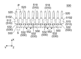
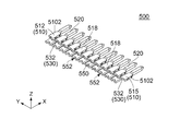
- the conductive member 500 has a plurality of held parts 510, a plurality of contact parts 520, a plurality of extension parts 530, and a plurality of connecting parts 550.
- the held portions 510 of the present embodiment are held by the holding portions 210, respectively.
- the held parts 510 are arranged in the left-right direction. More specifically, the held portion 510 is divided into two rows in the vertical direction. The held portions 510 in each row are arranged in the left-right direction.
- the held portion 510 is arranged so as to be rotationally symmetrical about an axis AX extending in the front-rear direction.
- the held portions 510 correspond to the accommodation holes 205 of the holding member 200, respectively.
- Each of the held parts 510 is press-fitted and housed in the corresponding housing hole 205.
- the held portion 510 of the present embodiment has a press-fitting protrusion 5102 that protrudes outward in the left-right direction.
- the press-fitting protrusion 5102 is press-fitted into the holding portion 210 of the accommodation hole 205 of the holding member 200.
- the plurality of held parts 510 include a rightmost held part 515, a leftmost held part 512, and at least one normal held part 518.
- the rightmost held part 515 is located on the rightmost side of the plurality of held parts 510 in the left-right direction.
- the leftmost held portion 512 is located on the leftmost side of the plurality of held portions 510 in the left-right direction.
- the normal held portion 518 is located between the rightmost held portion 515 and the leftmost held portion 512 in the left-right direction.
- the contact portions 520 of the present embodiment are arranged at intervals of the pitch P in the left-right direction.
- the contact portions 520 correspond to the held portions 510, respectively.
- Each of the contact portions 520 is located in front of the corresponding held portion 510 in the front-rear direction orthogonal to the left-right direction.
- the contact portion 520 of the present embodiment is a so-called pin contact (male contact).
- the contact portion 520 may be a socket contact (female contact).
- each of the extension portions 530 of the present embodiment extends rearward from any of the held portions 510 in the front-rear direction and projects rearward from the holding portion 210 in the front-rear direction.
- one extension portion 530 extends rearward from the rightmost held portion 515 in the front-rear direction.
- One extension 530 extends rearward from the leftmost held portion 512 in the front-rear direction.
- Two extension parts 530 extend rearward in the front-rear direction from one normal held part 518. The plurality of extension portions 530 are located apart from each other in the left-right direction.
- a part of the extension portion 530 is surrounded by the enclosure portion 220 in an orthogonal plane orthogonal to the front-rear direction.
- the orthogonal plane is the YZ plane. More specifically, a part of the extension 530 is located inside the enclosure 220. A part of the extension portion 530 is exposed inside the enclosure 220.
- the extension portion 530 of the present embodiment is provided with a weak portion 532 having low strength. More specifically, the weakened portion 532 has the least strength in the extension portion 530. Further, the weak portion 532 has a lower strength than the held portion 510 and the connecting portion 550.
- the weak portion 532 is a groove extending in the left-right direction. The present invention is not limited to this.
- the extension part 530 may be modified as long as a part of the extension part 530 is reduced in the cross-sectional area orthogonal to the front-rear direction and functions as the weak part 532.
- the weak portion 532 of the present embodiment is surrounded by the enclosing portion 220 in the orthogonal plane. More specifically, the weak portion 532 is located within the enclosure 220. The weak portion 532 is exposed inside the enclosure 220.
- the plurality of connecting portions 550 of the present embodiment are located apart from each other in the left-right direction.
- the plurality of connecting portions 550 are located behind the plurality of extending portions 530 in the front-rear direction.
- Each of the connection parts 550 connects the two extension parts 530 to each other.
- the two held portions 510 that are adjacent to each other in the left-right direction are connected to the two extended portions 530, respectively.
- Each of the connecting portions 550 has one extended portion 530 extending from one held portion 510 of the two held portions 510 located adjacent to each other in the left-right direction and the other extending portion 530 extending from the remaining one held portion 510.
- One of the extension portions 530 is connected.
- the connecting portion 550 can be removed from the conductive member 500 by breaking it off. More specifically, the connecting portion 550 can be separated from the conductive member 500 by dividing each of the two extending portions 530 into two in the front and rear direction at the weak portion 532.
- the size S of the connecting portion 550 is smaller than the pitch P between two adjacent contact portions 520. This prevents the connecting portions 550 from contacting each other.
- the connecting portion 550 of the present embodiment is surrounded by the enclosing portion 220 in the orthogonal plane. More specifically, the connecting portion 550 is located inside the enclosure 220. The connecting portion 550 is exposed inside the enclosure 220.
- the connecting portion 550 of the present embodiment has a recessed portion 552.
- the recessed portion 552 is located at the rear end of the connecting portion 550 in the front-rear direction.
- the recessed portion 552 is a recessed portion that is open rearward and is recessed forward.
- the recessed portion 552 is a portion for hooking a tool when the connecting portion 550 is broken off.
- connection part 550 Since the connection part 550 has the recessed part 552, the user inserts a tool into the recessed part 552 of the specific connection part 550 when dividing the two extension parts 530 connected by the specific connection part 550. Can be hooked. Therefore, it is possible to prevent the user from mistakenly removing the connecting portion 550 adjacent to the specific connecting portion 550.
- the shape of the connecting portion 550 is not limited to the above. That is, the connecting portion 550 may not have the recessed portion 552, and may have a shape different from that of the connecting portion 550 of the present embodiment. Further, the connecting portion 550 can be broken off from the conductive member 500 with a general-purpose tool such as radio pliers.
- the enclosure part 220 of the present embodiment encloses the extension part 530 and the connection part 550 in a plane orthogonal to the front-rear direction. That is, the holding member 200 has the enclosing portion 220 that encloses the extension portion 530 and the connecting portion 550 in the plane orthogonal to the front-rear direction.
- contacted portion 700 is made of metal.
- the contacted portion 700 is a so-called socket contact (female contact).
- the present invention is not limited to this.
- the contact part 520 is a socket contact
- the contacted part 700 may be a pin contact (male contact).
- the contacted portion 700 is held by the holding member 200.
- the contacted part 700 is in physical and electrical contact with the contact part 520 of the conductive member 500.
- the holding member 200 of the present embodiment holds the contacted portion 700 and the contact portion 520 of the conductive member 500 together.
- the holding member 200 of the connection device 100 according to the present embodiment has a seamless structure including a part that holds the contacted part 700 and another part that holds the contact part 520. Therefore, in the connection device 100 according to the present embodiment, when the contacted portion 700 is held by a part of the holding member 200 and the contact portion 520 is held by another part of the holding member 200 that is separate from the above part. Compared with, it is superior in terms of waterproofness.
- each of the cables 800 of the present embodiment extends in the front-rear direction.
- Each of the cables 800 has a metal core wire 810. The vicinity of the rear end of the core wire 810 is physically and electrically connected to the contacted portion 700.
- connection device 100 of the present embodiment further includes a cap 300, a first seal member (seal member) 400, and a second seal member 570.
- the cap 300 of the present embodiment has a rotationally symmetrical shape about an axis AX extending in the front-rear direction.
- the cap 300 has a closed rear end and an open front end. More specifically, the cap 300 has a rear surface 310 and a tubular portion 320.
- the rear surface 310 defines the rear end of the cap 300.
- the tubular portion 320 is located in front of the rear surface 310.
- the tubular portion 320 is connected to the front end of the rear surface 310.
- the tubular portion 320 has a substantially track shape when viewed along the front-rear direction.
- the tubular portion 320 has a substantially track shape that is long in the left-right direction on an orthogonal plane that is orthogonal to the front-rear direction.
- the cap 300 is attached to the enclosure 220.
- the cap 300 is located at the rear end of the connection device 100 in the front-rear direction.
- the cap 300 closes the opening 222 (see FIG. 2) of the enclosure 220.
- a part of the extension portion 530 is enclosed by the tubular portion 320 in the orthogonal plane. More specifically, in the attached state, a part of the extension portion 530 is located inside the tubular portion 320. In the attached state, a part of the extension portion 530 is exposed inside the tubular portion 320.
- the connecting portion 550 is surrounded by the tubular portion 320 in the orthogonal plane in the attached state where the cap 300 is attached to the enclosing portion 220. More specifically, in the attached state, the connecting portion 550 is located inside the tubular portion 320. In the attached state, the connecting portion 550 is exposed inside the tubular portion 320.
- the first seal member 400 of the present embodiment is made of an elastic insulator such as rubber.
- the first seal member 400 has a substantially track shape when viewed along the front-rear direction.
- the first seal member 400 has a substantially track shape that is long in the left-right direction on an orthogonal plane that is orthogonal to the front-rear direction.
- the first seal member 400 is located in front of the rear surface 310 of the cap 300 in the front-rear direction.
- the first seal member 400 is located outside the tubular portion 320 of the cap 300 in the orthogonal direction orthogonal to the front-rear direction.
- the first seal member 400 surrounds the tubular portion 320 of the cap 300 in the orthogonal plane.
- the first seal member 400 is in close contact with the tubular portion 320 in the orthogonal direction.
- the first seal member 400 In the attached state in which the cap 300 is attached to the enclosing portion 220, the first seal member 400 is located behind the held portion 510 of the conductive member 500 in the front-rear direction. In the attached state, the first seal member 400 is located behind the weak portion 532 in the front-rear direction. In the attached state, the first seal member 400 is located inside the enclosing portion 220 in the orthogonal direction. In the attached state, the first seal member 400 is in close contact with the enclosing portion 220 in the orthogonal direction.
- the first seal member 400 is interposed between the cap 300 and the enclosing portion 220. That is, the first seal member 400 seals the gap between the cap 300 and the enclosure 220 with water.
- second sealing member 570 of the present embodiment is made of an elastic insulator such as rubber.
- the second seal member 570 is located near the front end of the holding member 200 in the front-rear direction.
- the second seal member 570 is located in front of the contacted portion 700 in the front-rear direction.
- the second seal member 570 is in close contact with the holding member 200 in the orthogonal direction.
- the second seal member 570 is in close contact with the cable 800 in the orthogonal direction.
- the second seal member 570 is interposed between the holding member 200 and the cable 800 and between the cables 800. That is, the second seal member 570 seals water between the holding member 200 and the cable 800 and between the cables 800.
- the conductive portion including the contacted portion 700 and the conductive member 500 is the holding member 200 and the cap 300. It is sealed with water from the outside.
- the structure of the conductive member 500 is not limited to that described above.
- the conductive member 500 can be modified as follows.
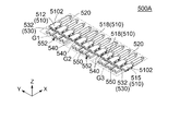
- the conductive member 500A of the connection device 100A of the present modified example has a plurality of held parts 510, a plurality of contact parts 520, a plurality of extension parts 530, and a plurality of extension part remaining parts. It has 540 and the some connection part 550.
- the present invention is not limited to this. As long as the conductive member 500A has a plurality of held parts 510, a plurality of contact parts 520, a plurality of extension parts 530, two remaining extension parts 540, and a plurality of coupling parts 550, the conductive member. 500A may be modified.
- each of the two extension parts 530 connected by the connection part 550 is separated into two in the front-rear direction, so that at least one connection part 550 and a part of the two extension parts 530 are removed.
- the connecting portion 550 may be modified.
- the conductive member 500A of this modification can be implemented by breaking off at least one connecting portion 550 from the conductive member 500A in the state of FIG. 2 in which the cap 300 is removed from the enclosing portion 220. Therefore, in the conductive member 500A, before the cable 800 is connected to the conductive member 500A via the contacted portion 700, the contact portions 520 can be set to have arbitrary conduction combinations. Similarly, in the conductive member 500A, even after the cable 800 is connected to the conductive member 500A through the contacted portion 700, the contact portions 520 can be in any combination of conduction.
- the held portion 510 of this modification is divided into a plurality of groups including at least a first group G1 and a second group G2 in the left-right direction. That is, the conductive member 500A of the present modified example has at least the held portion 510 included in the first group G1 and the held portion 510 included in the second group G2. More specifically, the held portion 510 is divided into three groups in the left-right direction, that is, a first group G1, a second group G2, and a third group G3.
- the first group G1 and the second group G2 are adjacent to each other in the left-right direction. More specifically, the first group G1 is adjacent to the left side of the second group G2 in the left-right direction. Further, the second group G2 and the third group G3 are adjacent to each other in the left-right direction. More specifically, the second group G2 is adjacent to the left side of the third group G3 in the left-right direction.
- the extension remaining portion 540 of the present modification is generated by breaking the connecting portion 550 from the conductive member 500 with a tool. Further, the extension remaining portion 540 of the present modified example is generated from the extension 530 that is connected to the removed connecting portion 550. That is, each of the extension remaining portions 540 is one of the two extension 530 separated in the front-rear direction. Therefore, each of the extension remaining portions 540 is shorter than the extension 530 in the front-rear direction.
- the rear end of the extension remaining portion 540 is a division mark generated when the extension 530 is divided in the weak portion 532 in the front-rear direction by a tool.
- the first group G1 includes one extension remaining portion 540.
- the extension remaining portion 540 of the first group G1 extends rearward in the front-rear direction from the held portion 510 closest to the second group G2 among the held portions 510 of the first group G1.
- the second group G2 includes two extension remaining portions 540.
- One extension remaining portion 540 of the second group G2 extends rearward in the front-rear direction from the held portion 510 closest to the first group G1 among the held portions 510 of the second group G2.
- the remaining one extension remaining portion 540 of the second group G2 extends rearward in the front-rear direction from the held portion 510 closest to the third group G3 among the held portions 510 of the second group G2.
- the third group G3 includes one extension remainder 540.
- the extension remaining portion 540 of the third group G3 extends rearward in the front-rear direction from the held portion 510 closest to the second group G2 among the held portions 510 of the third group G3.
- the present invention is not limited to this.
- the conductive member 500A may be modified as long as the conductive member 500A has the following configuration.
- the conductive member 500A includes two extension remaining portions 540.
- the held portion 510 is divided in the left-right direction into two groups, a first group G1 and a second group G2.
- One extension remaining portion 540 extends rearward in the front-rear direction from the held portion 510 closest to the second group G2 among the held portions 510 of the first group G1.
- the remaining one extension remaining portion 540 extends rearward in the front-rear direction from the held portion 510 closest to the first group G1 among the held portions 510 of the second group G2.
- the rear end of the extension remaining portion 540 of this modification is surrounded by the enclosure 220 in the orthogonal plane. More specifically, the rear end of the extension remaining portion 540 is located inside the enclosure 220. The rear end of the extension remaining portion 540 is exposed inside the enclosure 220.
- the rear end of the extension remaining portion 540 of the present modification is attached to the tubular portion 320 in the orthogonal plane. being surrounded. More specifically, in the attached state, the rear end of the extension remaining portion 540 is located inside the tubular portion 320. In the attached state, the rear end of the extension remaining portion 540 is exposed inside the tubular portion 320.
- each of the connection parts 550 connects the two extension parts 530 to each other.
- the two held portions 510 that are adjacent to each other in the left-right direction are connected to the two extended portions 530, respectively.
- the held portions 510 included in the first group G1 are electrically connected to each other by the extension portion 530 and the connecting portion 550.
- the held parts 510 included in the second group G2 are electrically connected to each other by the extension part 530 and the connection part 550.
- the held parts 510 included in the third group G3 are electrically connected to each other by the extension part 530 and the connection part 550.
- each of the held parts 510 included in the first group G1 is not electrically connected to any of the held parts 510 included in the second group G2.
- Each of the held parts 510 included in the first group G1 is not electrically connected to any of the held parts 510 included in the third group G3.
- Each of the held parts 510 included in the second group G2 is not electrically connected to any of the held parts 510 included in the third group G3.
- the conducting portion including the contacted portion 700 and the conductive member 500A is the holding member 200 and the cap 300. It is sealed with water from the outside.
- the connection device 900 of Patent Document 1 has a problem that the trace of the conductive member 950 caused by the removal of the connecting portion 956 is exposed in the exposure hole 9122. On the other hand, in the connection device 100A of this modification, such a problem does not occur. Therefore, the conductive portion, particularly the remaining portion 540 of the extended portion is prevented from coming into contact with water droplets.
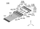
- the connecting device 100B As shown in FIG. 16, the connecting device 100B according to the second embodiment of the present invention has a first connector 600 and a second connector 650.
- first connector 600 As shown in FIG. 16, the connecting device 100B according to the second embodiment of the present invention has a first connector 600 and a second connector 650.
- second connector 650 As for the azimuth and direction in the present embodiment, the same expressions as in the first embodiment will be used below.
- the first connector 600 of the present embodiment includes a first holding member (holding member) 200B and a conductive member 500.
- the conductive member 500 is held by the first holding member 200B. That is, the connection device 100B includes the first holding member (holding member) 200B and the conductive member 500 held by the first holding member 200B.
- first holding member 200B of the present embodiment is made of an insulating member.
- the first holding member 200B has a plurality of accommodation holes 205B, an enclosing portion 220B, and a fitting portion 240.
- each of the accommodation holes 205B of the present embodiment penetrates the first holding member 200B in the front-rear direction.
- the accommodation hole 205B is located in front of the enclosure 220B in the front-rear direction. More specifically, the accommodation holes 205B are divided into two rows in the vertical direction. The accommodation holes 205B in each row are arranged in the left-right direction.
- the accommodation hole 205B is arranged so as to be rotationally symmetrical about an axis BX (see FIG. 18) extending in the front-rear direction.
- each of the accommodation holes 205B of this embodiment has a first holding portion (holding portion) 210B. That is, the first holding member (holding member) 200B of the present embodiment has the holding portion 210B.
- the first holding portion 210B of the present embodiment is the inner side surface of the accommodation hole 205B in the left-right direction.
- the first holding portion 210B is located in front of the enclosing portion 220B in the front-rear direction.
- the enclosure 220B of the present embodiment extends in the front-rear direction.
- the enclosure 220B defines the rear end of the first holding member 200B.
- the rear end of the enclosure 220B is open. That is, the enclosure 220B has the opening 222B at the rear end.
- the enclosure 220B has a rotationally symmetrical shape about an axis BX extending in the front-rear direction.
- the enclosure 220B has a substantially track shape when viewed from the rear.
- the enclosure 220B has a substantially track shape that is long in the left-right direction on an orthogonal plane that is orthogonal to the front-rear direction.
- the fitting portion 240 of this embodiment is located in front of the accommodation hole 205B in the front-rear direction.
- the front end of the fitting portion 240 is open.
- the contact portion 520 of the conductive member 500 is surrounded by the fitting portion 240 in the orthogonal plane.
- the front end of the fitting portion 240 is located in front of the front end of the contact portion 520 of the conductive member 500 in the front-rear direction.
- the fitting part 240 has a contacted part accommodation part 242.
- the contacted part accommodation part 242 of the present embodiment is a space extending in the front-rear direction.
- the contacted portion accommodation portion 242 communicates with the accommodation hole 205B in the front-rear direction.
- the contact portion 520 of the conductive member 500 is located inside the contacted portion accommodation portion 242. The contact portion 520 is exposed in the contacted portion accommodation portion 242.
- the conductive member 500 has a plurality of held parts 510, a plurality of contact parts 520, a plurality of extension parts 530, and a plurality of connecting parts 550. There is.
- the configuration of the conductive member 500 of the present embodiment is similar to that of the conductive member 500 of the first embodiment. Therefore, details are omitted.
- a part of the extension part 530 of the present embodiment is surrounded by the enclosing part 220B in the orthogonal plane. More specifically, a part of the extension portion 530 is located inside the enclosing portion 220B. A part of the extension portion 530 is exposed inside the enclosing portion 220B.
- the weak portion 532 of the present embodiment is surrounded by the enclosing portion 220B in the orthogonal plane. More specifically, the weak portion 532 is located inside the enclosing portion 220B. The weak portion 532 is exposed in the enclosing portion 220B.
- the connecting portion 550 of the present embodiment is surrounded by the enclosing portion 220B in the orthogonal plane. More specifically, the connecting portion 550 is located inside the enclosing portion 220B. The connecting portion 550 is exposed in the enclosing portion 220B.
- the first connector 600 of the present embodiment further includes a cap 300B and a first seal member (seal member) 400B.
- the cap 300B of the present embodiment has a rotationally symmetrical shape about an axis BX extending in the front-rear direction.
- the cap 300B has a closed rear end and an open front end. More specifically, the cap 300B has a rear surface 310B and a tubular portion 320B.
- the rear surface 310B defines the rear end of the cap 300B.
- the tubular portion 320B is located in front of the rear surface 310B.
- the tubular portion 320B is connected to the front end of the rear surface 310B.
- the tubular portion 320B has a substantially track shape when viewed along the front-rear direction.
- the cylindrical portion 320B has a substantially track shape that is long in the left-right direction on an orthogonal plane that is orthogonal to the front-rear direction.
- the cap 300B is located at the rear end of the first connector 600 in the front-rear direction.
- the cap 300B is attached to the enclosure 220B.
- the cap 300B closes the opening 222B (see FIG. 19) of the enclosure 220B.
- part of the extension portion 530 is enclosed by the tubular portion 320B in the orthogonal plane. More specifically, in the attached state, a part of the extension portion 530 is located inside the tubular portion 320B. In the attached state, part of the extension portion 530 is exposed inside the tubular portion 320B.
- the weak portion 532 is enclosed by the tubular portion 320B in the orthogonal plane. More specifically, in the attached state, the weak portion 532 is located inside the tubular portion 320B. In the attached state, the weak portion 532 is exposed in the tubular portion 320B.
- the connecting portion 550 is enclosed by the tubular portion 320B in the orthogonal plane. More specifically, in the attached state, the connecting portion 550 is located inside the tubular portion 320B. In the attached state, the connecting portion 550 is exposed inside the tubular portion 320B.
- first seal member 400B of the present embodiment is made of an elastic insulator such as rubber.
- the first seal member 400B has a substantially track shape when viewed along the front-rear direction.
- the first seal member 400B has a substantially track shape that is long in the left-right direction on an orthogonal plane that is orthogonal to the front-rear direction.
- the first seal member 400B is located in front of the rear surface 310B of the cap 300B in the front-rear direction.
- the first seal member 400B is located outside the tubular portion 320B of the cap 300B in the orthogonal direction.
- the first seal member 400B surrounds the tubular portion 320B of the cap 300B in the orthogonal plane.
- the first seal member 400B is in close contact with the tubular portion 320B in the orthogonal direction.
- the first seal member 400B In the attached state in which the cap 300B is attached to the enclosing portion 220B, the first seal member 400B is located behind the held portion 510 of the conductive member 500 in the front-rear direction. In the attached state, the first seal member 400B is located behind the weak portion 532 in the front-rear direction. In the attached state, the first seal member 400B is located inside the enclosing portion 220B in the orthogonal direction. In the attached state, the first seal member 400B is in close contact with the enclosing portion 220B in the orthogonal direction. That is, the first seal member (seal member) 400B is interposed between the cap 300B and the enclosing portion 220B. The first seal member 400B seals water between the cap 300B and the enclosure 220B.
- connection device 100B of the present embodiment further includes a cap 300B attached to the enclosure 220B and a first seal member (seal member) 400B interposed between the cap 300B and the enclosure 220B.
- the second connector 650 of the present embodiment includes a second holding member 660, a second seal member 570, a third seal member 580, a contacted portion 700, and a cable 800. I have it. Of these, the second seal member 570, the contacted portion 700, and the cable 800 are the same as those in the first embodiment. Therefore, details are omitted.
- the second holding member 660 of this embodiment is separate from the first holding member 200B of the first connector 600.
- the second holding member 660 holds the contacted portion 700 and the cable 800.
- the second holding member 660 has a fitted portion 662.
- the fitted portion 662 of the present embodiment is located at the rear end of the second holding member 660 in the front-rear direction.
- the fitted part 662 has a substantially track shape when viewed along the front-rear direction.
- the fitted portion 662 has a substantially track shape that is long in the left-right direction on an orthogonal plane orthogonal to the front-rear direction.
- the fitted portion 662 surrounds the contacted portion 700 in the orthogonal plane.
- the rear end of the fitted portion 662 is located rearward of the rear end of the contacted portion 700 in the front-rear direction.
- third seal member 580 of the present embodiment is made of an elastic insulator such as rubber.
- the third seal member 580 has a substantially track shape when viewed along the front-rear direction.
- the third seal member 580 has a substantially track shape that is long in the left-right direction on an orthogonal plane that is orthogonal to the front-rear direction.
- the third seal member 580 is located behind the cable 800 in the front-rear direction.
- the third seal member 580 is located in front of the rear end of the fitted portion 662 in the front-rear direction.
- the third seal member 580 is located outside the fitted portion 662 in the orthogonal direction.
- the third seal member 580 surrounds the fitted portion 662 in the orthogonal plane.
- the third seal member 580 is in close contact with the fitted portion 662 in the orthogonal direction.
- the third seal member 580 is positioned inside the fitting portion 240 in the orthogonal direction in the fitted state where the first connector 600 and the second connector 650 are fitted to each other. doing.
- the third seal member 580 is in close contact with the fitting portion 240 in the orthogonal direction.
- the third seal member 580 is interposed between the fitting portion 240 and the fitted portion 662. That is, in the fitted state, the third seal member 580 seals water between the fitting portion 240 and the fitted portion 662.
- the structure of the conductive member 500 is not limited to that described above.
- the conductive member 500 can be modified as follows.
- a conductive member (not shown) of the connection device (not shown) of the present modification has a plurality of held parts 510, a plurality of contact parts 520, a plurality of extension parts 530, It has a plurality of extension remaining portions 540 and a plurality of connecting portions 550. That is, in the conductive member of the present modification, each of the two extension portions 530 is separated into two in the front-rear direction, so that at least one connecting portion 550 and a part of the two extension portions 530 are removed. ing.
- the present invention is not limited to this.
- the conductive member has a plurality of held parts 510, a plurality of contact parts 520, a plurality of extension parts 530, two remaining extension parts 540, and a plurality of connection parts 550, the conductive member is It may be modified.
- the conductive member of this modification is the same as the conductive member 500A of the modification of the first embodiment. Therefore, details are omitted.
- the rear end of the extension remaining portion 540 of the present modification is surrounded by the enclosing portion 220B in the orthogonal plane. More specifically, the rear end of the extension remaining portion 540 is located inside the enclosure 220B. The rear end of the extension remaining portion 540 is exposed inside the enclosure 220B.
- the rear end of the extension remaining portion 540 of the present modification is enclosed by the tubular portion 320B in the orthogonal plane. More specifically, in the attached state, the rear end of the extension remaining portion 540 is located inside the tubular portion 320B. In the attached state, the rear end of the extension remaining portion 540 is exposed in the tubular portion 320B.
- connection device of the present modification when the second connector 650 is fitted to the first connector 600 attached to the enclosing portion 220B of the cap 300B, the contacted portion is A conductive portion including 700 and a conductive member is water-sealed from the outside of the first connector 600, the second connector 650 and the cap 300B.
- the connection device 900 of Patent Document 1 has a problem that the trace of the conductive member 950 caused by the removal of the connecting portion 956 is exposed in the exposure hole 9122. On the other hand, such a problem does not occur even in the connecting device of the present modification. Therefore, the conductive portion, particularly the remaining portion 540 of the extended portion is prevented from coming into contact with water droplets.
- connection device 100B The structure of the connection device 100B is not limited to that described above.
- the connection device 100B may be modified as follows.
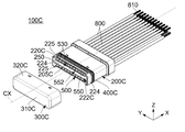
- connection device 100C of the present modified example includes a holding member 200C, a cap 300C, a first seal member (seal member) 400C, a second seal member 570, a conductive member 500, and a contacted member.
- the unit 700 and a plurality of cables 800 are provided.
- the second seal member 570, the conductive member 500, the contacted portion 700, and the cable 800 of this modification are the same as those in the above-described embodiment. Therefore, details are omitted.
- the holding member 200C of the present modification is made of an insulating member.
- the holding member 200C has a plurality of accommodation holes 205C, an enclosure 220C, and a partition 250.
- the accommodation hole 205C of this modified example is similar to the accommodation hole 205 of the first embodiment. Therefore, details are omitted.
- the enclosure 220C of this modification extends in the front-rear direction.
- the enclosure 220C defines the rear end of the holding member 200C.
- the rear end of the enclosure 220C is open. That is, the enclosure 220C has the opening 222C at the rear end.
- the enclosing portion 220C has a rotationally symmetrical shape about an axis CX extending in the front-rear direction.
- the enclosure 220C of the present modification has two side portions 224 and two cutout portions 225.
- the upper end of the side portion 224 of this modification is curved inward in the left-right direction.
- the lower end of the side portion 224 is curved inward in the left-right direction.
- the two side portions 224 are respectively located at both ends in the left-right direction of the holding member 200C.
- the side portion 224 defines the rear end of the holding member 200C in the front-rear direction.
- the rear end of each of the side portions 224 is located rearward of the rear end of the connecting portion 550 in the front-rear direction.
- the connecting portion 550 of the conductive member 500 is blocked by the side portion 224 from the right side and is not visible. Further, in the state where the cap 300C is not attached to the enclosing portion 220C, the connecting portion 550 of the conductive member 500 is blocked by the side portion 224 from the left side and is not visible. As a result, in the state where the cap 300C is not attached to the enclosing portion 220C, the connecting portion 550 of the conductive member 500 is prevented from being inadvertently hit by the tool from the left and right directions.
- each of the cutout portions 225 of this modified example is recessed forward in the front-rear direction.
- the two cutout portions 225 are located at both ends in the vertical direction of the enclosing portion 220C.
- Each of the cutout portions 225 is located between the two side portions 224 in the left-right direction.
- the connecting portion 550 of the conductive member 500 is visible through the cutout portion 225. That is, in the state where the cap 300C is not attached to the enclosing portion 220C, the connecting portion 550 of the conductive member 500 is visible along the vertical direction through the cutout portion 225.
- the connecting portion 550 of the conductive member 500 is visible from above through the cutout portion 225.
- the connecting portion 550 of the conductive member 500 is visible from below through the cutout portion 225 when the cap 300C is not attached to the enclosing portion 220C. This allows the user to hook the tool on the recess 552 from the outer side in the vertical direction when breaking off the connecting portion 550.
- the partition part 250 of this modification has a flat plate shape orthogonal to the vertical direction.
- the partition part 250 defines the rear end of the holding member 200C in the front-rear direction.
- the rear end of the partition part 250 is located rearward of the rear end of the connecting part 550 in the front-rear direction.
- the partition part 250 is located between the two side parts 224 in the left-right direction.
- the two side parts 224 are located at both ends of the partition part 250 in the left-right direction.
- the two side portions 224 are connected to the left and right ends of the partition portion 250, respectively. That is, the partition part 250 is reinforced by the two side parts 224, and the vertical bending is prevented.
- the partition part 250 is located between the two rows of the accommodation holes 205C in the vertical direction.
- the partition part 250 is located between two rows of the held parts 510 in the vertical direction.
- the partition part 250 includes, in the vertical direction, a connecting part 550 that is connected to the held parts 510 in the upper two rows and the held parts 510 in the lower two rows and the extended parts 530. It is located between the connection part 550 connected via 530. Accordingly, when the user breaks the connecting portion 550, which is connected to the held portion 510 in the upper row through the extension portion 530, using the tool, the held portion 510 and the extension portion 530 in the lower row. It is avoided that the user accidentally brings the tool into contact with the connecting portion 550 connected via the.
- the cap 300C of this modification has a rotationally symmetrical shape about an axis CX extending in the front-rear direction.
- the cap 300C has a closed rear end and an open front end. More specifically, the cap 300C has a rear surface 310C and a tubular portion 320C.
- the rear surface 310C defines the rear end of the cap 300C.
- the cylindrical portion 320C is located in front of the rear surface 310C.
- the cylindrical portion 320C is connected to the front end of the rear surface 310C.
- the tubular portion 320C has a substantially track shape when viewed along the front-rear direction.
- the cylindrical portion 320C has a substantially track shape that is long in the left-right direction on an orthogonal plane that is orthogonal to the front-rear direction.
- the cap 300C of this modification is attached to the enclosure 220C.
- the cap 300C In the attached state where the cap 300C is attached to the enclosing portion 220C, the cap 300C is located at the rear end of the connection device 100C in the front-rear direction. In the attached state, the cap 300C closes the opening 222C of the enclosure 220C.
- the rear ends of the side part 224 and the partition part 250 are located rearward of the rear end of the connecting part 550 in the front-rear direction.
- the rear ends of the side portions 224 and the partition 250 abut the rear surface 310C of the cap 300C before the rear end of the connecting portion 550 abuts the rear surface 310C of the cap 300C. That is, the side part 224 and the partition part 250 prevent the rear end of the coupling part 550 from hitting the rear surface 310C of the cap 300C when the cap 300C is attached to the enclosing part 220C.
- a part of the extension portion 530 faces a part of the tubular portion 320C through the cutout portion 225 in the vertical direction.
- the connecting portion 550 faces a part of the tubular portion 320C through the cutout portion 225 in the vertical direction.
- the first seal member (seal member) 400C of this modification is made of an elastic insulator such as rubber.
- the first seal member 400C has a substantially track shape when viewed in the front-rear direction.
- the first seal member 400C has a substantially track shape that is long in the left-right direction on an orthogonal plane orthogonal to the front-rear direction.
- the first seal member 400C is located in front of the connecting portion 550 in the front-rear direction.
- the first seal member 400C is in close contact with the enclosing portion 220C in the orthogonal direction.
- the first seal member 400C is located in front of the rear surface 310C of the cap 300C in the front-rear direction.
- the first seal member 400C is located inside the tubular portion 320C of the cap 300C in the orthogonal direction orthogonal to the front-rear direction. In the attached state, the first seal member 400C is surrounded by the tubular portion 320C of the cap 300C in the orthogonal plane. In the attached state, the first seal member 400C is in close contact with the tubular portion 320C in the orthogonal direction. In the attached state, the first seal member 400C is interposed between the cap 300C and the enclosing portion 220C.
- the first seal member 400C seals the gap between the cap 300C and the enclosing portion 220C with water.
- the conductive portion including the contacted portion 700 and the conductive member 500 is water-sealed from the outside of the holding member 200C and the cap 300C.
- the structure of the conductive member 500 is not limited to that described above.
- the conductive member 500 can be modified as follows.
- a conductive member (not shown) of the connection device (not shown) of the present modification has a plurality of held parts 510, a plurality of contact parts 520, a plurality of extension parts 530, It has a plurality of extension remaining portions 540 and a plurality of connecting portions 550. That is, in the conductive member of the present modification, each of the two extension portions 530 is separated into two in the front-rear direction, so that at least one connecting portion 550 and a part of the two extension portions 530 are removed. ing.
- the present invention is not limited to this.
- the conductive member has a plurality of held parts 510, a plurality of contact parts 520, a plurality of extension parts 530, two remaining extension parts 540, and a plurality of connection parts 550, the conductive member is It may be modified.
- the conductive member of this modification is the same as the conductive member 500A of the modification of the first embodiment. Therefore, details are omitted.
- connection device of the present modification when the cap 300C is attached to the enclosing portion 220C, the conductive portion including the contacted portion 700 and the conductive member is the holding member 200C. Also, the cap 300C is water-sealed from outside.
- the connection device 900 of Patent Document 1 has a problem that the trace of the conductive member 950 caused by the removal of the connecting portion 956 is exposed in the exposure hole 9122. On the other hand, such a problem does not occur even in the connecting device of the present modification. Therefore, the conductive portion, particularly the remaining portion 540 of the extended portion is prevented from coming into contact with water droplets.
- the first seal members 400, 400B are provided outside the tubular portions 320, 320B of the caps 300, 300B in the orthogonal direction, but the present invention is not limited to this. Not limited to. That is, the first seal members 400 and 400B may be provided inside the tubular portions 320 and 320B of the caps 300 and 300B in the orthogonal direction. Even when the first seal members 400 and 400B are provided on the tubular portions 320 and 320B of the caps 300 and 300B as described above, when the caps 300 and 300B are attached to the enclosing portions 220 and 220B, the first seal members are attached.
- the first sealing members 400 and 400B can secure the space between the caps 300 and 300B and the enclosing portions 220 and 220B. Can be water sealed.
- the present invention is based on Japanese Patent Application No. 2018-244577 filed with the Japan Patent Office on December 27, 2018, the contents of which are incorporated herein by reference.
Landscapes
- Connector Housings Or Holding Contact Members (AREA)
Abstract
Dispositif de connexion pourvu d'un élément de maintien et d'un élément conducteur. L'élément de maintien comporte une partie de maintien. L'élément conducteur comporte une pluralité de parties à maintenir, une pluralité de parties de contact, une pluralité de parties d'extension, et une pluralité de parties de couplage. Chaque partie de la pluralité de parties d'extension s'étend vers l'arrière à partir de l'une quelconque des parties à maintenir dans la direction longitudinale, et fait saillie vers l'arrière à partir de la partie de maintien dans la direction longitudinale. La pluralité de parties d'extension sont situées à distance les unes des autres dans la direction latérale. La pluralité de parties de couplage sont situées à distance les unes des autres dans la direction latérale. La pluralité de parties de couplage sont situées derrière la pluralité de parties d'extension dans la direction longitudinale. Chacune des parties de couplage couple deux parties d'extension l'une à l'autre. Deux parties à maintenir, qui sont adjacentes l'une à l'autre dans la direction latérale, sont respectivement couplées à deux parties d'extension.
Priority Applications (3)
| Application Number | Priority Date | Filing Date | Title |
|---|---|---|---|
| US17/289,005 US11621517B2 (en) | 2018-12-27 | 2019-09-30 | Connecting apparatus |
| CN201980076149.9A CN113056848B (zh) | 2018-12-27 | 2019-09-30 | 连接装置 |
| JP2020562369A JP7387639B2 (ja) | 2018-12-27 | 2019-09-30 | 接続装置 |
Applications Claiming Priority (2)
| Application Number | Priority Date | Filing Date | Title |
|---|---|---|---|
| JP2018244577 | 2018-12-27 | ||
| JP2018-244577 | 2018-12-27 |
Publications (1)
| Publication Number | Publication Date |
|---|---|
| WO2020137064A1 true WO2020137064A1 (fr) | 2020-07-02 |
Family
ID=71128901
Family Applications (1)
| Application Number | Title | Priority Date | Filing Date |
|---|---|---|---|
| PCT/JP2019/038580 Ceased WO2020137064A1 (fr) | 2018-12-27 | 2019-09-30 | Dispositif de connexion |
Country Status (4)
| Country | Link |
|---|---|
| US (1) | US11621517B2 (fr) |
| JP (1) | JP7387639B2 (fr) |
| CN (1) | CN113056848B (fr) |
| WO (1) | WO2020137064A1 (fr) |
Cited By (1)
| Publication number | Priority date | Publication date | Assignee | Title |
|---|---|---|---|---|
| US12683317B2 (en) | 2023-03-08 | 2026-07-14 | Japan Aviation Electronics Industry, Limited | Structure, including a contact, a holding member, and a retaining reinforcement member |
Citations (6)
| Publication number | Priority date | Publication date | Assignee | Title |
|---|---|---|---|---|
| JPH0587836U (ja) * | 1992-04-30 | 1993-11-26 | 沖電線株式会社 | キャリア付きコネクタ端子 |
| JPH0773938A (ja) * | 1993-09-01 | 1995-03-17 | Yazaki Corp | ジョイントコネクタおよびジョイント端子 |
| JP2002117950A (ja) * | 2001-07-19 | 2002-04-19 | Sumitomo Wiring Syst Ltd | ジョイントコネクタ |
| JP2002260752A (ja) * | 2001-03-02 | 2002-09-13 | Kasuga Electric Works Ltd | 電気機器端子部の短絡板 |
| WO2013042576A1 (fr) * | 2011-09-20 | 2013-03-28 | 株式会社オートネットワーク技術研究所 | Plaque conductrice et connecteur de jonction |
| JP2016167404A (ja) * | 2015-03-10 | 2016-09-15 | 矢崎総業株式会社 | 雄ジョイントコネクタ |
Family Cites Families (10)
| Publication number | Priority date | Publication date | Assignee | Title |
|---|---|---|---|---|
| JP3248335B2 (ja) | 1994-02-18 | 2002-01-21 | 住友電装株式会社 | ジョイントコネクタ及びジョイントコネクタの製造方法 |
| US5957725A (en) * | 1995-07-05 | 1999-09-28 | Auto Splice Systems Inc. | Continuous molded plastic components or assemblies |
| US6447331B1 (en) * | 1999-05-19 | 2002-09-10 | Sumitomo Wiring Systems, Ltd. | Joint connector and method of producing joint connector |
| JP3402459B2 (ja) | 1999-06-01 | 2003-05-06 | 住友電装株式会社 | ジョイントコネクタ |
| US6729903B1 (en) | 2002-12-04 | 2004-05-04 | Maytag Corporation | Quick connect/disconnect electrical connector having an extended insulating tab |
| JP2005116473A (ja) * | 2003-10-10 | 2005-04-28 | Sumitomo Wiring Syst Ltd | ジョイントコネクタ、ジョイント端子、及びジョイント端子の製造方法 |
| JP2005116472A (ja) | 2003-10-10 | 2005-04-28 | Sumitomo Wiring Syst Ltd | ジョイントコネクタ及びジョイントコネクタの製造方法 |
| JP2006253017A (ja) * | 2005-03-11 | 2006-09-21 | Sumitomo Wiring Syst Ltd | ジョイントコネクタ |
| JP2012064506A (ja) * | 2010-09-17 | 2012-03-29 | Yazaki Corp | 連鎖端子 |
| JP6018975B2 (ja) | 2013-05-28 | 2016-11-02 | 矢崎総業株式会社 | ジョイントコネクタ |
-
2019
- 2019-09-30 WO PCT/JP2019/038580 patent/WO2020137064A1/fr not_active Ceased
- 2019-09-30 US US17/289,005 patent/US11621517B2/en active Active
- 2019-09-30 CN CN201980076149.9A patent/CN113056848B/zh active Active
- 2019-09-30 JP JP2020562369A patent/JP7387639B2/ja active Active
Patent Citations (6)
| Publication number | Priority date | Publication date | Assignee | Title |
|---|---|---|---|---|
| JPH0587836U (ja) * | 1992-04-30 | 1993-11-26 | 沖電線株式会社 | キャリア付きコネクタ端子 |
| JPH0773938A (ja) * | 1993-09-01 | 1995-03-17 | Yazaki Corp | ジョイントコネクタおよびジョイント端子 |
| JP2002260752A (ja) * | 2001-03-02 | 2002-09-13 | Kasuga Electric Works Ltd | 電気機器端子部の短絡板 |
| JP2002117950A (ja) * | 2001-07-19 | 2002-04-19 | Sumitomo Wiring Syst Ltd | ジョイントコネクタ |
| WO2013042576A1 (fr) * | 2011-09-20 | 2013-03-28 | 株式会社オートネットワーク技術研究所 | Plaque conductrice et connecteur de jonction |
| JP2016167404A (ja) * | 2015-03-10 | 2016-09-15 | 矢崎総業株式会社 | 雄ジョイントコネクタ |
Cited By (1)
| Publication number | Priority date | Publication date | Assignee | Title |
|---|---|---|---|---|
| US12683317B2 (en) | 2023-03-08 | 2026-07-14 | Japan Aviation Electronics Industry, Limited | Structure, including a contact, a holding member, and a retaining reinforcement member |
Also Published As
| Publication number | Publication date |
|---|---|
| JPWO2020137064A1 (fr) | 2020-07-02 |
| CN113056848B (zh) | 2023-04-07 |
| US20210408722A1 (en) | 2021-12-30 |
| US11621517B2 (en) | 2023-04-04 |
| CN113056848A (zh) | 2021-06-29 |
| JP7387639B2 (ja) | 2023-11-28 |
Similar Documents
| Publication | Publication Date | Title |
|---|---|---|
| US11056836B2 (en) | Shield terminal compatible with multiple housings and shield connector using the same | |
| US10931056B2 (en) | Connector | |
| US11088486B2 (en) | Shield terminal and shield connector | |
| TWI611641B (zh) | 連接器及連接器組合體 | |
| US7481675B2 (en) | Connector assembly with cavity sealing plug | |
| CN113273037B (zh) | 连接器及外导体 | |
| US10840648B2 (en) | Shield terminal and shield connector | |
| CN112714985B (zh) | 连接器 | |
| ES2968386T3 (es) | Ensamblaje de conectores | |
| JP5480652B2 (ja) | コネクタ | |
| US10205264B2 (en) | Joint connector | |
| CN110235317A (zh) | 屏蔽端子 | |
| JP2017098079A (ja) | シールドコネクタ、及びコネクタ付きシールドケーブル | |
| WO2015133145A1 (fr) | Ensemble connecteur | |
| CN110235318A (zh) | 屏蔽端子 | |
| JP2023021590A (ja) | コネクタ | |
| JP6579438B2 (ja) | シールドコネクタ、及びコネクタ付きシールドケーブル | |
| JP2016207601A (ja) | ジョイントコネクタ | |
| WO2017199756A1 (fr) | Connecteur électrique muni de bornes de signaux et d'une borne de mise à la terre et dispositif de connecteur électrique utilisant ledit connecteur électrique | |
| US10971849B2 (en) | Connector and connector assembly | |
| JP2013048048A (ja) | コネクタ | |
| JP3121438U (ja) | 電源用コネクタ | |
| JP7387639B2 (ja) | 接続装置 | |
| JP3689849B2 (ja) | コネクタ | |
| JP5582870B2 (ja) | コネクタ |
Legal Events
| Date | Code | Title | Description |
|---|---|---|---|
| 121 | Ep: the epo has been informed by wipo that ep was designated in this application |
Ref document number: 19904798 Country of ref document: EP Kind code of ref document: A1 |
|
| ENP | Entry into the national phase |
Ref document number: 2020562369 Country of ref document: JP Kind code of ref document: A |
|
| NENP | Non-entry into the national phase |
Ref country code: DE |
|
| 122 | Ep: pct application non-entry in european phase |
Ref document number: 19904798 Country of ref document: EP Kind code of ref document: A1 |