WO2020137077A1 - スピニング加工装置、スピニング加工方法、加工ローラ - Google Patents
スピニング加工装置、スピニング加工方法、加工ローラ Download PDFInfo
- Publication number
- WO2020137077A1 WO2020137077A1 PCT/JP2019/039550 JP2019039550W WO2020137077A1 WO 2020137077 A1 WO2020137077 A1 WO 2020137077A1 JP 2019039550 W JP2019039550 W JP 2019039550W WO 2020137077 A1 WO2020137077 A1 WO 2020137077A1
- Authority
- WO
- WIPO (PCT)
- Prior art keywords
- processing
- tubular member
- diameter
- roller
- spinning
- Prior art date
- Legal status (The legal status is an assumption and is not a legal conclusion. Google has not performed a legal analysis and makes no representation as to the accuracy of the status listed.)
- Ceased
Links
Images


Classifications
-
- B—PERFORMING OPERATIONS; TRANSPORTING
- B21—MECHANICAL METAL-WORKING WITHOUT ESSENTIALLY REMOVING MATERIAL; PUNCHING METAL
- B21D—WORKING OR PROCESSING OF SHEET METAL OR METAL TUBES, RODS OR PROFILES WITHOUT ESSENTIALLY REMOVING MATERIAL; PUNCHING METAL
- B21D22/00—Shaping without cutting, by stamping, spinning, or deep-drawing
- B21D22/14—Spinning
- B21D22/16—Spinning over shaping mandrels or formers
-
- B—PERFORMING OPERATIONS; TRANSPORTING
- B21—MECHANICAL METAL-WORKING WITHOUT ESSENTIALLY REMOVING MATERIAL; PUNCHING METAL
- B21D—WORKING OR PROCESSING OF SHEET METAL OR METAL TUBES, RODS OR PROFILES WITHOUT ESSENTIALLY REMOVING MATERIAL; PUNCHING METAL
- B21D41/00—Application of procedures in order to alter the diameter of tube ends
- B21D41/04—Reducing; Closing
-
- B—PERFORMING OPERATIONS; TRANSPORTING
- B21—MECHANICAL METAL-WORKING WITHOUT ESSENTIALLY REMOVING MATERIAL; PUNCHING METAL
- B21H—MAKING PARTICULAR METAL OBJECTS BY ROLLING, e.g. SCREWS, WHEELS, RINGS, BARRELS, BALLS
- B21H1/00—Making articles shaped as bodies of revolution
Definitions
- the present invention relates to a spinning processing device and a spinning processing method. More specifically, the present invention relates to a spinning device and a spinning method for processing the end shape of a tubular member. Further, the present invention relates to a processing roller used in a spinning device and a spinning method.
- a spinning processing device is used when processing the groove part on the opening side end of the bottomed cylindrical material.
- a spinning processing device is used when processing the groove part on the opening side end of the bottomed cylindrical material.
- Patent Document 1 first, an open end of a bottomed tubular material is made smaller in diameter than a body portion by forging, and then a pressing roller having a convex portion is pressed against the peripheral portion of the material, A spinning method is known in which a groove is formed in the peripheral portion.
- the open end and the body of a bottomed tubular material have approximately the same diameter
- the convex part of the pressing roller enters the material, the material pressed by the convex part Flow into both sides of the groove and the groove becomes tapered.
- the tubular member When it is necessary to make the inner diameter of the opening-side end smaller than the inner diameter of the body (to form a large step) as the final shape in the spinning process for forming the groove at the end of the cylindrical member, the tubular member The diameter of the end portion is reduced in advance, and the groove portion is formed by using a tubular member having an opening end portion having a smaller diameter than the body portion. Therefore, two processes, that is, a diameter reduction process for reducing the diameter of the end of the tubular member by forging in advance and a grooving process for forming a groove on the outer peripheral surface of the tubular member are required.
- An object of the present invention is to provide a spinning processing apparatus and a spinning processing method capable of simply performing a plurality of processes in plastic processing for processing an end portion of a tubular member.
- the present inventor arranged an end of the tubular member by arranging the rotating shaft of the processing roller for reducing the diameter of the end of the tubular member substantially perpendicular to the rotating shaft of the tubular member.
- the present invention has been completed by finding that it is possible to perform the diameter reduction processing for reducing the diameter of a portion and the end surface pressing processing for pressing the end surface of the tubular member using one processing roller. That is, the present invention is the following spinning processing device, spinning processing method, and processing roller.
- the spinning processing apparatus of the present invention for solving the above-mentioned problems is a spinning processing apparatus for plastically processing the end of a tubular member, and a diameter reduction processing surface used for diameter reduction processing of the end of the tubular member, and It is characterized in that it is provided with a processing roller having an end surface pressing processing surface used for the end surface pressing processing for pressing the end surface.
- this spinning processing apparatus it is possible to perform the diameter reduction processing for reducing the diameter of the end portion of the tubular member and the end surface pushing processing for pressing the surface of the end portion of the tubular member with one processing roller. .. Therefore, it is possible to provide a simplified spinning processing apparatus and a simplified spinning processing method in the plastic processing for processing the end portion of the tubular member.
- An embodiment of the spinning machine of the present invention is characterized by including a grooving processing roller for forming a groove on the outer peripheral surface of the tubular member. According to the above feature, since the processing roller for performing the diameter reducing process and the end face pressing process and the groove forming process roller for performing the groove forming process are provided, the steps of the diameter reducing process, the groove forming process and the end face pressing process are performed. It becomes possible to process with one plastic working.
- the spinning processing apparatus of the present invention for solving the above-mentioned problems is a spinning processing apparatus for plastically processing the end of a tubular member, and a grooving roller that forms a groove on the outer peripheral surface of the tubular member, and a tubular member.
- the processing roller since the rotation axis of the processing roller is arranged substantially perpendicular to the rotation axis of the tubular member, the processing roller has a diameter reduction process of reducing the diameter of the end of the tubular member, It is possible to add the action of an end face pushing process of pushing the end face of the tubular member. Therefore, according to the spinning processing apparatus of the present invention, of the three types of plastic processing of the diameter reduction processing, the grooving processing, and the end surface pressing processing, the diameter reduction processing and the end surface pressing processing are performed continuously by one roller for a short time. Since it can be carried out, it is possible to treat the substance with two types of plastic working.
- the processing roller is characterized in that it has a taper portion whose diameter is reduced in the rotational axis direction. According to this feature, when the processing roller is moved in the rotation axis direction to press the outer peripheral surface of the tubular member to perform the diameter reduction process, the outer peripheral surface of the tubular member is moved along the tapered portion. Since the diameter is reduced, the action of the pressing force is dispersed, and stable diameter reduction processing can be performed.
- a processing roller of the present invention for solving the above-mentioned problems is a processing roller used in a spinning processing device, and a diameter reduction processing surface used for diameter reduction processing of an end portion of a tubular member, and a surface of the end portion. It is characterized in that it is provided with a processing roller having an end surface pressing processing surface used for the end surface pressing processing for pressing. According to the processing roller of the present invention, the end face pressing process can be performed together with the diameter reducing process, so that the steps of the diameter reducing process and the end face pressing process can be performed by one plastic working.
- the spinning method of the present invention for solving the above-mentioned problems is a spinning method for plastically processing the end of a tubular member, in which a diameter reduction treatment step of reducing the diameter of the end of the tubular member is performed.
- An end face pushing process step of pressing a surface, and the diameter reducing process step and the end face pushing process step are performed by one roller.
- this spinning processing method it is possible to perform the diameter reduction processing for reducing the diameter of the end portion of the tubular member and the end face pressing processing for pressing the surface of the end portion of the tubular member using one processing roller. Therefore, the plastic working for working the end portion of the tubular member can be simplified.
- Spinning is a method of plastic processing in which a rotating plate-shaped or tubular member is pressed by a roller or spatula to form it.
- parts and products such as brake parts (brake pistons for disc brakes), engine parts, tire wheels, household containers, decorative crafts, lighting equipment, communication equipment, boilers, tanks, nozzles, etc. It is a thing.
- the spinning device and the spinning method of the present invention can be used for plastic working of the end portion of the tubular member. More specifically, it is used for reducing the diameter of the end of the tubular member, and further, reducing the diameter of the end of the tubular member and pushing the end face to press the end face. It is preferably used for plastic working. In particular, it is suitable for use in the spinning process to form a groove at the end of a tubular member when the final shape requires that the inner diameter of the opening-side end be smaller than the inner diameter of the body (forming a large step). can do.
- FIG. 1 is a schematic explanatory view showing the structure of a spinning processing apparatus 1A according to the first embodiment of the present invention.
- the spinning processing apparatus 1A according to the first embodiment of the present invention includes a processing roller 2A for performing a diameter reduction process and an end face pushing process on an end portion of a tubular member T, and a tubular member T. It is provided with a grooving processing roller 3 for forming a groove portion on the outer peripheral surface.
- This spinning processing apparatus 1A has a rotation mechanism (not shown) that rotates about a rotation axis R1, a main shaft 5 connected to this rotation mechanism, and a fixing for fixing the tubular member T to the tip of the main shaft 5.
- the tubular member T is fixed to the tip of the main shaft 5 by the fixing means 4A, and is attached so as to rotate around the rotation axis R1.
- the spinning processing apparatus 1A includes a processing roller holder 6 for mounting the processing roller 2A.
- the processing roller 2A is attached to the processing roller holder 6 and rotates about the rotation axis R2.
- the rotation axis R2 is installed so as to be substantially perpendicular to the rotation axis R1 of the tubular member T.
- the spinning device 1A includes a groove processing roller holder 7 for mounting the groove processing roller 3.
- the grooving roller 3 is attached to the grooving roller holder 7 and rotates about the rotation axis R3.
- the rotation axis R3 is installed so as to be substantially parallel to the rotation axis R1 of the tubular member T.
- the fixing means 4A is means for fixing the tubular member T to the tip of the main shaft 5 connected to the rotating mechanism.
- the fixing means 4A according to the first embodiment is a chuck that is provided on the main shaft 5 and holds and fixes the outer peripheral surface of the tubular member T.
- the fixing means 4A may be any fixing means.
- the fixing means 4A is inserted into the tubular member T and pressed from the bottom of the tubular member T so that the tip end of the main shaft 5 is pressed.
- a core rod or the like for fixing the tubular member T to the base plate may be used.
- the tubular member T may be a tubular member made of a material suitable for plastic working, and may have a bottom, for example.
- the cylindrical shape is not particularly limited, and may be a cylindrical shape, an elliptic cylindrical shape, or a polygonal cylindrical shape. The cylindrical shape is preferable from the viewpoint of realizing stable rotation.
- the material suitable for plastic working is not particularly limited, but a steel material can be used.
- the tubular member T of the first embodiment is a bottomed cylindrical tubular member obtained by forging.
- the tubular member T may not have a reduced diameter at its end portion, or may have a reduced diameter.
- the processing roller 2A is a roller having a diameter reduction processing surface used for diameter reduction processing for reducing the diameter of the end portion of the tubular member and an end surface pressing processing surface used for end surface pressing processing for pressing the end surface.
- the rotation axis R2 of the processing roller 2A is arranged substantially perpendicular to the rotation axis R1 of the tubular member T, and the rotation axis R2 rotates in the axial direction and rotates.
- substantially vertical includes a case where deviation from vertical occurs within a common sense range in device design technology.
- the case where they are perpendicular on different planes is also included.
- the processing roller 2A has a cylindrical processing roller main body 23a and a cylindrical end surface pressing portion 22a having a diameter smaller than that of the processing roller main body 23.
- a taper portion 21a having a diameter reduced in the direction of the rotation axis R2 is formed between the pressing portions 22a.
- the processing roller body 23a is a structure that can rotate around the rotation axis R2.
- the shape may be any shape, and may be a disc shape, an elliptic column shape, a polygonal column shape, or the like other than the column shape. From the viewpoint of stable rotation, it is preferably cylindrical or disc-shaped.
- the end surface pressing portion 22a has a structure protruding from the processing roller body 23a and rotates coaxially with the processing roller body 23a.
- the peripheral surface drawn by the rotation of the end surface pressing portion 22a is an end surface pressing processing surface 25a for pressing the end surface of the tubular member T, and the end surface pressing processing surface 25a is pressed against the end surface of the tubular member T.
- the shape of the end surface pushing portion 22a can be appropriately set depending on the shape of the end surface of the tubular member T. For example, a truncated cone shape whose diameter is reduced or expanded from the processing roller body 23a, a columnar shape having a rim portion on the outer peripheral surface, and the like can be given.
- the taper portion 21a has a structure formed between the processing roller body 23a and the end surface pushing portion 22a, and rotates coaxially with the processing roller body 23a and the end surface pushing portion 22a. Further, it has a shape in which the diameter is reduced from the processing roller main body 23a toward the end face pressing portion 22a in the direction of the rotation axis R2.
- the tapered portion 21 may have any shape as long as it has a diameter that decreases from the processing roller body 23a toward the end surface pressing portion 22a.
- the cross section of the tapered portion becomes a linear shape from the processing roller body toward the end surface pressing portion.
- the cross section of the tapered portion may have a curved shape from the processing roller body toward the end surface pressing portion.
- the peripheral surface drawn by the rotation of the taper portion 21a is a diameter reduction processing surface 24a for pressing the outer peripheral surface of the tubular member T, and the diameter reduction processing surface 24a is pressed against the outer peripheral surface of the tubular member T. By doing so, the diameter reduction processing is performed.
- the taper portion has a linear cross section, a constant force is applied from the processing roller to the outer peripheral surface of the tubular member T during the diameter reduction process, so that stable plastic working can be performed.
- FIGS. 3A and 4 show another embodiment of the processing roller of the present invention.
- the processing rollers 2B and 2D illustrated in FIGS. 3A and 4A include a disk-shaped processing roller main body 23b and a tapered portion 21b having a curved cross section, and the peripheral surface of the tapered portion 21b is curved.
- the shape-reduced surface 24b is provided.
- the processing roller 2C shown in FIG. 3B is one in which a truncated cone-shaped taper portion 21c is provided so as to project from the inner region of the end surface of the cylindrical processing roller body 23a.
- a peripheral surface of the taper portion 21c forms a diameter-reduced surface 24c linearly.
- the processing roller 2D illustrated in FIG. 4A has an end surface pressing portion 22b having a truncated cone shape whose diameter is reduced from the processing roller body 23b.
- the peripheral surface of the end surface pressing portion 22b forms an inclined end surface pressing processing surface 25b.
- the processing roller 2E illustrated in FIG. 4B has a cylindrical end surface pressing portion 22c having a rim portion 26 on the outer peripheral surface.
- the peripheral surface of the end surface pressing portion 22c forms an arcuate end surface pressing processing surface 25c.
- the processing roller 2A moves in the axial direction of the rotary shaft R2 and presses the end portion of the tubular member T from the outer peripheral surface.
- the diameter of the end of the tubular member T is reduced by being pressed by the processing roller 2A, the outer peripheral surface of the end of the tubular member T is reduced in diameter along the tapered portion 21a of the processing roller 2A.
- the diameter is contracted toward the axial center of the tubular member without significantly changing the thickness (difference between the outer diameter and the inner diameter) of the tubular member.
- the position of the outer peripheral surface of the end portion of the tubular member T after the diameter reduction processing (the outer diameter of the end portion of the tubular member T) is determined by the position of the end surface on the small diameter side of the tapered portion 21a. Therefore, the diameter of the outer peripheral surface of the end portion of the tubular member T after the diameter reduction processing can be set by adjusting the moving distance of the processing roller 2A in the axial direction of the rotation axis R2.
- the processing roller 2A moves in a direction in which the direction parallel to the axis of the rotation axis R1 and the direction parallel to the rotation axis R2 are combined, and the end surface of the tubular member T is moved to the end surface of the processing roller 2A.
- the range on the opening side of the groove on the outer peripheral surface of the tubular member T is pressed toward the inner diameter side.
- the outer diameter of the end of the tubular member T on the opening side can be set within a predetermined range.
- the processing roller 2A may move in the direction parallel to the axis of the rotation axis R1 during the end face pressing process.
- the grooving processing roller 3 is a roller for performing grooving processing for forming a groove on the outer peripheral surface of the tubular member T. As shown in FIG. 2B, the rotation axis R3 of the grooving processing roller 3 is arranged parallel to the rotation axis R1 of the tubular member T, and the axis of the rotation axis R3 is close to the axis of the rotation axis R1. It is designed to be movable.
- the moving direction of the grooving roller is shown by the black arrow in the figure.
- the direction of the rotation axis R3 of the grooving processing roller 3 is not particularly limited and may be arranged so as to be non-parallel to the rotation axis R1 of the tubular member T.
- the grooving treatment roller 3 has a cylindrical grooving treatment roller main body 32 and a groove forming portion 31 protruding from the outer peripheral surface of the grooving treatment roller main body 32. ..
- the shape and width of the groove forming portion 31 can be appropriately designed according to the shape and width of the groove portion formed on the outer peripheral surface of the tubular member T.
- the grooving process roller 3 moves the axis of the rotary shaft R3 closer to the axis of the rotary shaft R1, and presses the outer peripheral surface of the tubular member T by the groove forming portion 31.
- a groove portion is formed on the outer peripheral surface of the tubular member T.
- the grooving processing by the grooving processing roller 3 and the end surface pressing processing by the end surface pressing portion 22a of the processing roller 2A be performed at the same time.
- the end face pressing process during the grooving process it is possible to further secure the wall thickness of the groove portion.
- FIG. 5 shows an enlarged view of the area surrounded by the broken line frame in FIG. 2(B).
- the processing roller 2A in FIG. 5 shows the arrangement at the time when the diameter reduction processing is completed.
- the outer peripheral surface of the tubular member T is reduced in diameter along the taper portion 21a by the reduction treatment (the reduced diameter region is referred to as "reduced diameter region D").
- reduced diameter region D By forming the groove portion G in the reduced diameter region D, it is possible to suppress the problem that the material of the tubular member T that flows during the grooving process flows to both sides of the groove forming portion 31a.
- the spinning process for forming the groove at the end of the tubular member it is preferably used when it is necessary to make the inner diameter of the opening-side end smaller than the inner diameter of the body (to form a large step) in the final shape. can do.
- the processing roller 2A is arranged at the time of the diameter reduction processing so that the tapered portion 21a is arranged in the range where the groove portion G is formed.
- the processing roller 2A is arranged so that the reduced diameter region D is entirely included within the region where the groove portion G is formed. It suffices that the reduced diameter region D partially overlaps.
- the upper end of the reduced diameter region D is preferable to arrange the upper end of the reduced diameter region D above the groove G. By disposing the upper end of the diameter-reduced area D above the groove G, the area where the groove G and the diameter-reduced area D overlap can be increased.
- the distance d1 from the lower end of the reduced diameter region D to the lower end of the groove G is larger than the distance d2 of the end face pressing surface 24a moving in the direction parallel to the rotation axis R1 during the end face pressing process.
- the diameter reduction process and the grooving process will be described with reference to FIGS.
- the outer peripheral surface of the end portion of the tubular member T is formed on the small diameter side end portion of the taper portion 21a of the processing roller 2A and the taper portion 21a.
- the end of the tubular member T is reduced in diameter by being pressed by the diameter-reduction processing surface 24a composed of the peripheral surface.
- the reduced diameter state of the end of the tubular member T is shown by the broken line of the tubular member T in FIG.
- the outer peripheral surface of the tubular member T is in contact with the diameter reduction processing surface 24a of the processing roller 2A.
- the diameter is contracted toward the axial center of the tubular member without significantly changing the thickness (difference between the outer diameter and the inner diameter) of the tubular member.
- ⁇ It is preferable to stop the diameter reduction process at a position larger than the outer diameter of the open end of the final product.
- the remaining diameter reduction processing until reaching the outer diameter of the open end of the final product is performed during or after the end face pressing treatment. The details of the remaining diameter reduction processing will be described later together with the end face pushing processing.
- the groove forming portion 31 of the grooving process roller 3 is inserted into the outer peripheral surface of the tubular member T at the position of the reduced diameter region D, and the machining is performed.
- the end surface pressing portion 22a of the roller 2A presses the end surface of the tubular member. Since the grooving process is performed on the reduced diameter region D, the material of the tubular member T is prevented from flowing to the outer peripheral surfaces on both sides of the groove portion G, and the occurrence of a convex portion on the outer peripheral surface of the tubular member T due to a defect is suppressed. can do. Further, since the end face pushing process can suppress the flow of the material in the direction of the rotation axis R1 when the groove portion G is formed, the thickness of the groove portion G can be secured.
- the processing roller 2A moves in the axial direction of the rotation axis R2 to perform the remaining diameter reduction process.
- an unintended diameter reduction of the open end of the tubular member T may occur, and the outer diameter of the open end of the final product may be uneven.
- the outer diameter of the open end of the tubular member T can be adjusted to a predetermined size by performing the diameter reducing process.
- the movement of the processing roller 2A during the end face pressing process may be obliquely moved in a direction in which a direction parallel to the axis of the rotation axis R1 and a direction parallel to the rotation axis R2 are combined, or parallel to the axis of the rotation axis R1.
- the movement in this direction and the movement in the direction parallel to the rotation axis R2 may be performed separately.
- the outer diameter of the opening end of the tubular member T is finally adjusted. From the viewpoint, it is preferable to stop the movement in the direction parallel to the rotation axis R2 last.
- the spinning method of the present invention is, in the spinning method of plastically processing the end of the tubular member, a diameter reduction processing step of reducing the diameter of the end of the tubular member, and an end face pressing processing for pressing the surface of the end. And a step of performing the diameter reduction processing step and the end surface pushing processing step by one roller. Further, the spinning method of the present invention may include a grooving process step of forming a groove on the outer peripheral surface of the tubular member.
- the diameter reduction processing step is performed, then the grooving processing step and the end face pushing processing step.
- the grooving process step and the end face pushing process step may be performed simultaneously or separately.
- the diameter reduction process may be divided into two or more times.
- the first diameter reduction processing step is intended to suppress the material of the tubular member from flowing to the outer peripheral surfaces on both sides of the groove portion during the grooving processing.
- the final diameter reduction processing step is intended to adjust the outer diameter of the open end of the final product. Since the grooving process and end face pressing process may cause some changes in the outer diameter of the open end of the final product, the final diameter reduction process step may be stopped at the end of all processes. preferable.
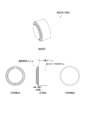
- FIG. 6 shows a perspective view, a front view, a left side view and a right side view of the processing roller 2A of the present invention.
- the back view, the top view, and the bottom view have the same shape as the front view.
- the processing roller 2A of the present invention is an article to be used by being attached to a spinning processing device in the plastic processing of a material such as a steel material.
- the processing roller 2A has a diameter reducing process for reducing the diameter of the end surface of the tubular member, and the tubular member.
- the end face pushing process is performed to push the end face.
- the processing roller 2A has a processing roller main body 23a, an end surface pressing portion 22a, and a taper portion 21a.
- the diameter reducing process is performed by the tapered peripheral surface of the tapered portion 21a having a truncated cone shape and the surface of the small diameter side end portion of the tapered portion 21a, and the end surface pressing process is performed by the peripheral surface of the cylindrical end surface pressing portion.
- the main part of the shape of the processing roller 2A of the present invention is a region from the taper peripheral surface of the taper portion 21a to the peripheral surface of the end surface pushing portion 22a (the area between the arrows shown in the front view of FIG. 6). is there.
- FIG. 7 is a schematic explanatory view showing the structure of a spinning processing apparatus 1B according to the second embodiment of the present invention.
- the spinning device 1B according to the second embodiment of the present invention includes a fixing means 4A, which is a chuck, as a fixing means for fixing the tubular member T to the tip of the main shaft 5, and a core.
- the fixing means 4B composed of a rod is provided.
- the spinning processing apparatus 1A of 1st Embodiment is the same.
- the core rod is a cylindrical member having a diameter smaller than the inner diameter of the tubular member T, and one end of the core rod is inserted into the tubular member T and the bottom of the tubular member T is pressed against the tip of the main shaft 5.
- the tubular member T is fixed to the tip of the main shaft 5.
- the outer diameter of the core rod to be large, the inner peripheral surface of the groove portion of the processed tubular member T can be pressed by the peripheral surface of the core rod.
- the other end of the core rod is fixed to a driven mechanism (not shown), and the core rod rotates as the tubular member T rotates.
- this second spinning device 1B the fixing of the tubular member T in the direction of the rotation axis R1 is stabilized by the fixing means 4B composed of a core rod. Therefore, the shape of the end surface of the tubular member T formed by the end surface pressing process is flattened, and a product having an excellent end surface shape can be obtained.
- the spinning device and the spinning method of the present invention can be used for plastic working of the end portion of the tubular member. More specifically, it can be used for reducing the diameter of the end of the tubular member. For example, it can be used to manufacture parts and products such as brake parts (brake pistons for disc brakes), engine parts, tire wheels, household containers, decorative crafts, lighting equipment, communication equipment, boilers, tanks, nozzles, etc. You can
- the spinning device and the spinning method of the present invention can perform the end face pushing process of the end portion of the tubular member by using one working roller, in the plastic working for performing the diameter reducing process and the end face pushing process. It can be used more suitably.
- the processing roller of the present invention can be applied to a spinning processing device and used for reducing the diameter of the end of a tubular member. Furthermore, since the processing roller of the present invention is also capable of end face pressing processing of the end portion of the tubular member, it can be used more suitably in plastic processing in which diameter reduction processing and end surface pressing processing are performed.
- the processing roller of the present invention is applied to an existing spinning processing apparatus so that the diameter reduction processing and the end surface pressing processing can be performed by the spinning processing apparatus that performs the diameter reduction processing and the end surface pressing processing by different rollers. It can be easily changed to a spinning processing device that can be performed with one processing roller.
Landscapes
- Engineering & Computer Science (AREA)
- Mechanical Engineering (AREA)
- Shaping Metal By Deep-Drawing, Or The Like (AREA)
Abstract
本発明の課題は、筒状部材の端部を加工する塑性加工において、複数の処理を簡潔に施すことが可能なスピニング加工装置及びスピニング加工方法を提供することである。 上記課題を解決するために、筒状部材の端部の縮径処理に使用する縮径処理面と、前記端部の面を押圧する端面押し処理に使用する端面押し処理面と、を有する加工ローラを備えることを特徴とする、スピニング加工装置を提供する。
Description
本発明は、スピニング加工装置及びスピニング加工方法に関するものである。更に詳しくは、筒状部材の端部の形状を加工するためのスピニング加工装置及びスピニング加工方法に関するものである。また、本発明は、スピニング加工装置及びスピニング加工方法に使用する加工ローラに関するものである。
ブレーキピストンの製造方法において、有底筒状の素材の開口側端部に溝部を加工する際に、スピニング加工装置を使用している。例えば、特許文献1に示すように、まず、鍛造によって有底筒状の素材の開口端部を胴部より小径とし、次に、凸部を有する押圧ローラをこの素材の周部に押し付けて、周部に溝部を形成するスピニング加工方法が知られている。ここで、有底筒状の素材の開口端部と胴部をほぼ同径とした場合には、押圧ローラの凸部を素材へ進入させた際に、凸部に押された素材が凸部の両側に流れ、溝部がテーパ状となる。そして、凸部の両側に流れて余った素材は、溝部の両側の外周面にあまり部分を形成し、最終製品の溝部の形状に不具合を発生する。一方、特許文献1に示すように、予め鍛造により有底筒状の素材の開口端部を胴部より小径とした場合には、素材の凸部の両側への流れを抑制することができる。
筒状部材の端部に溝部を形成するスピニング加工において、最終形状として開口側端部の内径を胴部の内径よりも小さくする(大きな段差を形成する)必要がある場合には、筒状部材の端部を予め縮径しておき、開口端部を胴部より小径とした筒状部材を用いて溝部を形成する。そのため、予め鍛造により筒状部材の端部を縮径する縮径処理と、筒状部材の外周面に溝部を形成する溝入れ処理の2つの処理が必要となっている。
本発明の課題は、筒状部材の端部を加工する塑性加工において、複数の処理を簡潔に施すことが可能なスピニング加工装置及びスピニング加工方法を提供することである。
本発明者は、上記課題について鋭意検討した結果、筒状部材の端部を縮径する加工ローラの回転軸を、筒状部材の回転軸と略垂直に配置することにより、筒状部材の端部を縮径する縮径処理と、筒状部材の端部の面を押圧する端面押し処理を一つの加工ローラを用いて処理することが可能であることを見出して本発明を完成させた。
すなわち、本発明は、以下のスピニング加工装置、スピニング加工方法、加工ローラである。
すなわち、本発明は、以下のスピニング加工装置、スピニング加工方法、加工ローラである。
上記課題を解決するための本発明のスピニング加工装置は、筒状部材の端部を塑性加工するスピニング加工装置において、筒状部材の端部の縮径処理に使用する縮径処理面と、前記端部の面を押圧する端面押し処理に使用する端面押し処理面と、を有する加工ローラを備えることを特徴とするものである。
このスピニング加工装置によれば、筒状部材の端部を縮径する縮径処理と、筒状部材の端部の面を押圧する端面押し処理を一つの加工ローラで処理することが可能となる。そのため、筒状部材の端部を加工する塑性加工において、簡素化されたスピニング加工装置及びスピニング加工方法を提供することができる。
このスピニング加工装置によれば、筒状部材の端部を縮径する縮径処理と、筒状部材の端部の面を押圧する端面押し処理を一つの加工ローラで処理することが可能となる。そのため、筒状部材の端部を加工する塑性加工において、簡素化されたスピニング加工装置及びスピニング加工方法を提供することができる。
また、本発明のスピニング加工装置の一実施態様としては、筒状部材の外周面に溝部を形成する溝入れ処理ローラを備えることを特徴とするものである。
上記特徴によれば、縮径処理と端面押し処理を行うための加工ローラと、溝入れ処理を行うための溝入れ処理ローラを備えるため、縮径処理、溝入れ処理及び端面押し処理の工程を、1つの塑性加工で処理することが可能となる。
上記特徴によれば、縮径処理と端面押し処理を行うための加工ローラと、溝入れ処理を行うための溝入れ処理ローラを備えるため、縮径処理、溝入れ処理及び端面押し処理の工程を、1つの塑性加工で処理することが可能となる。
上記課題を解決するための本発明のスピニング加工装置は、筒状部材の端部を塑性加工するスピニング加工装置において、筒状部材の外周面に溝部を形成する溝入れ処理ローラと、筒状部材の端部の縮径処理に使用する縮径処理面を有する加工ローラと、を備え、前記加工ローラの回転軸は、前記筒状部材の回転軸と略垂直に配置されることを特徴とするものである。
本発明のスピニング加工装置によれば、加工ローラの回転軸が筒状部材の回転軸と略垂直に配置されるため、加工ローラに、筒状部材の端部を縮径する縮径処理と、筒状部材の端部の面を押圧する端面押し処理の作用を付すことが可能となる。よって、本発明のスピニング加工装置によれば、縮径処理、溝入れ処理及び端面押し処理の3種類の塑性加工のうち、縮径処理と端面押し処理を1つのローラによる連続した動作で短時間に行えるので、実質は2種類の塑性加工で処理することが可能となる。
本発明のスピニング加工装置によれば、加工ローラの回転軸が筒状部材の回転軸と略垂直に配置されるため、加工ローラに、筒状部材の端部を縮径する縮径処理と、筒状部材の端部の面を押圧する端面押し処理の作用を付すことが可能となる。よって、本発明のスピニング加工装置によれば、縮径処理、溝入れ処理及び端面押し処理の3種類の塑性加工のうち、縮径処理と端面押し処理を1つのローラによる連続した動作で短時間に行えるので、実質は2種類の塑性加工で処理することが可能となる。
また、本発明のスピニング加工装置の一実施態様としては、加工ローラは、回転軸方向に縮径するテーパ部を有することを特徴とするものである。
この特徴によれば、加工ローラを回転軸方向に向かって移動させて、筒状部材の外周面を押圧して縮径処理を行う際に、筒状部材の外周面は、テーパ部に沿って縮径されるため、押圧する力の作用が分散して、安定した縮径処理を実施することができる。
この特徴によれば、加工ローラを回転軸方向に向かって移動させて、筒状部材の外周面を押圧して縮径処理を行う際に、筒状部材の外周面は、テーパ部に沿って縮径されるため、押圧する力の作用が分散して、安定した縮径処理を実施することができる。
上記課題を解決するための本発明の加工ローラは、スピニング加工装置に使用する加工ローラであって、筒状部材の端部の縮径処理に使用する縮径処理面と、前記端部の面を押圧する端面押し処理に使用する端面押し処理面を有する加工ローラを備えることを特徴とするものである。
本発明の加工ローラによれば、縮径処理と共に端面押し処理も可能であるため、縮径処理及び端面押し処理の工程を、1つの塑性加工で処理することが可能となる。
本発明の加工ローラによれば、縮径処理と共に端面押し処理も可能であるため、縮径処理及び端面押し処理の工程を、1つの塑性加工で処理することが可能となる。
上記課題を解決するための本発明のスピニング加工方法は、筒状部材の端部を塑性加工するスピニング加工方法において、筒状部材の端部を縮径する縮径処理ステップと、前記端部の面を押圧する端面押し処理ステップと、を備え、前記縮径処理ステップ及び前記端面押し処理ステップを一つのローラにより行うことを特徴とするものである。
このスピニング加工方法によれば、一つの加工ローラを用いて、筒状部材の端部を縮径する縮径処理と、筒状部材の端部の面を押圧する端面押し処理を施すことが可能となるため、筒状部材の端部を加工する塑性加工を簡素化することができる。
このスピニング加工方法によれば、一つの加工ローラを用いて、筒状部材の端部を縮径する縮径処理と、筒状部材の端部の面を押圧する端面押し処理を施すことが可能となるため、筒状部材の端部を加工する塑性加工を簡素化することができる。
本発明によれば、筒状部材の端部を加工する塑性加工において、複数の処理を簡潔に施すことが可能なスピニング加工装置及びスピニング加工方法を提供することができる。
以下、図面を参照しつつ本発明に係るスピニング加工装置、スピニング加工方法及び加工ローラの実施態様を詳細に説明する。
なお、実施態様に記載するスピニング加工装置、スピニング加工方法及び加工ローラについては、本発明に係るスピニング加工装置、スピニング加工方法及び加工ローラを説明するために例示したに過ぎず、これに限定されるものではない。
なお、実施態様に記載するスピニング加工装置、スピニング加工方法及び加工ローラについては、本発明に係るスピニング加工装置、スピニング加工方法及び加工ローラを説明するために例示したに過ぎず、これに限定されるものではない。
スピニング加工とは、回転する板状や筒状の部材をローラやへらで押し付けて成形する塑性加工の一手法である。例えば、ブレーキ部品(ディスクブレーキ用のブレーキピストン等)、エンジン部品、タイヤホイール、家庭用容器、装飾工芸品、照明器具、通信機器、ボイラ、タンク、ノズルなどの部品・製品の製造に利用されるものである。
本発明のスピニング加工装置及びスピニング加工方法は、筒状部材の端部の塑性加工のために利用することができる。より具体的には、筒状部材の端部の縮径処理のために利用するものであり、さらには、筒状部材の端部の縮径処理と、端部の面を押圧する端面押し処理を行う塑性加工に好適に利用するものである。
特に、筒状部材の端部に溝部を形成するスピニング加工において、最終形状として開口側端部の内径を胴部の内径よりも小さくする(大きな段差を形成する)必要がある場合に好適に利用することができる。
特に、筒状部材の端部に溝部を形成するスピニング加工において、最終形状として開口側端部の内径を胴部の内径よりも小さくする(大きな段差を形成する)必要がある場合に好適に利用することができる。
〔第1の実施態様〕
(スピニング加工装置)
図1は、本発明の第1の実施態様におけるスピニング加工装置1Aの構造を示す概略説明図である。本発明の第1の実施態様におけるスピニング加工装置1Aは、図1に示すように、筒状部材Tの端部に縮径処理と端面押し処理を行うための加工ローラ2A、筒状部材Tの外周面に溝部を形成するための溝入れ処理ローラ3を備えるものである。
(スピニング加工装置)
図1は、本発明の第1の実施態様におけるスピニング加工装置1Aの構造を示す概略説明図である。本発明の第1の実施態様におけるスピニング加工装置1Aは、図1に示すように、筒状部材Tの端部に縮径処理と端面押し処理を行うための加工ローラ2A、筒状部材Tの外周面に溝部を形成するための溝入れ処理ローラ3を備えるものである。
このスピニング加工装置1Aは、回転軸R1を軸として回転する回転機構(不図示)と、この回転機構に連結された主軸5と、その主軸5の先端に筒状部材Tを固定するための固定手段4Aを備える。筒状部材Tは、固定手段4Aにより主軸5の先端に固定され、回転軸R1を中心に回転するように取り付けられる。
スピニング加工装置1Aは、加工ローラ2Aを取り付けるための加工ローラホルダ6を備える。加工ローラ2Aは、加工ローラホルダ6に取り付けられ、回転軸R2を軸として回転する。なお、回転軸R2は、筒状部材Tの回転軸R1と略垂直となるように設置されている。
スピニング加工装置1Aは、溝入れ処理ローラ3を取り付けるための溝入れ処理ローラホルダ7を備える。溝入れ処理ローラ3は、溝入れ処理ローラホルダ7に取り付けられ、回転軸R3を軸として回転する。なお、回転軸R3は、筒状部材Tの回転軸R1と略平行となるように設置されている。
以下に、各部材について、詳細に説明する。
<固定手段>
固定手段4Aは、回転機構に連結された主軸5の先端に、筒状部材Tを固定するための手段である。第一の実施態様の固定手段4Aは、主軸5に設けられ、筒状部材Tの外周面を挟持して固定するチャックである。
また、固定手段4Aは、どのような固定手段でもよく、上記チャックの他にも、例えば、筒状部材Tの内部に挿入し、筒状部材Tの底部から押し当てることにより、主軸5の先端に筒状部材Tを固定する芯棒などが挙げられる。
<固定手段>
固定手段4Aは、回転機構に連結された主軸5の先端に、筒状部材Tを固定するための手段である。第一の実施態様の固定手段4Aは、主軸5に設けられ、筒状部材Tの外周面を挟持して固定するチャックである。
また、固定手段4Aは、どのような固定手段でもよく、上記チャックの他にも、例えば、筒状部材Tの内部に挿入し、筒状部材Tの底部から押し当てることにより、主軸5の先端に筒状部材Tを固定する芯棒などが挙げられる。
筒状部材Tは、塑性加工に適した材料で形成された筒状の部材であればよく、例えば、有底のものであってもよい。また、筒状の形状は、特に制限されず、円筒形状、楕円筒形状、多角筒形状でもよい。安定した回転を実現するという観点から、円筒形状であることが好ましい。また、塑性加工に適した材料は、特に制限されないが、鋼材が挙げられる。第一の実施態様の筒状部材Tは、鍛造により得られた有底円筒形状の筒状部材である。なお、筒状部材Tは、端部が縮径されていないものであっても、縮径したものであってもよい。
<加工ローラ>
加工ローラ2Aは、筒状部材の端部を縮径する縮径処理に使用する縮径処理面と、前記端部の面を押圧する端面押し処理に使用する端面押し処理面を有するローラであって、筒状部材Tの端部の外周面を押圧する縮径処理と、筒状部材Tの端部の面に押圧する端面押し処理を施すためのローラである。図2(A)、図2(B)に示すように、加工ローラ2Aの回転軸R2は、筒状部材Tの回転軸R1と略垂直に配置されており、回転軸R2の軸方向及び回転軸R1の軸と平行な方向へ移動可能に設計されている(加工ローラ2Aの移動方向は、図中の黒塗り矢印に示す。)。なお、回転軸R1と回転軸R2との配置において、「略垂直」とは、装置の設計技術において、常識的な範囲内で垂直からずれが生じる場合を含むものである。また、回転軸R1と回転軸R2が同一の平面上で垂直に交差する場合の他にも、異なる平面上で垂直となる場合(いわゆる「ねじれの位置」の場合)も含む。
加工ローラ2Aは、筒状部材の端部を縮径する縮径処理に使用する縮径処理面と、前記端部の面を押圧する端面押し処理に使用する端面押し処理面を有するローラであって、筒状部材Tの端部の外周面を押圧する縮径処理と、筒状部材Tの端部の面に押圧する端面押し処理を施すためのローラである。図2(A)、図2(B)に示すように、加工ローラ2Aの回転軸R2は、筒状部材Tの回転軸R1と略垂直に配置されており、回転軸R2の軸方向及び回転軸R1の軸と平行な方向へ移動可能に設計されている(加工ローラ2Aの移動方向は、図中の黒塗り矢印に示す。)。なお、回転軸R1と回転軸R2との配置において、「略垂直」とは、装置の設計技術において、常識的な範囲内で垂直からずれが生じる場合を含むものである。また、回転軸R1と回転軸R2が同一の平面上で垂直に交差する場合の他にも、異なる平面上で垂直となる場合(いわゆる「ねじれの位置」の場合)も含む。
図2(A)に示すように、加工ローラ2Aは、円柱状の加工ローラ本体23aと、加工ローラ本体23より小径の円柱状の端面押部22aを有しており、加工ローラ本体23aと端面押部22aの間には、回転軸R2方向に縮径するテーパ部21aが形成されている。
加工ローラ本体23aは、回転軸R2を中心に回転可能な構造物である。形状としては、どのような形状でもよく、円柱状のほかにも、円盤状、楕円柱状、多角柱状などでもよい。安定して回転するという観点から、円柱状や円盤状であることが好ましい。
端面押部22aは、加工ローラ本体23aから突設した構造であり、加工ローラ本体23aと同軸に回転するものである。端面押部22aが回転することにより描かれる周面は、筒状部材Tの端面を押圧するための端面押し処理面25aであり、この端面押し処理面25aを筒状部材Tの端面に押圧することにより、端面押し処理を行なう。端面押部22aの形状は、筒状部材Tの端面の形状によって適宜設定することができる。例えば、加工ローラ本体23aから縮径又は拡径する円錐台状や、外周面にリム部を有する円柱状などが挙げられる。
テーパ部21aは、加工ローラ本体23aと端面押部22aの間に形成される構造であり、加工ローラ本体23a及び端面押部22aと同軸に回転するものである。また、回転軸R2方向に、加工ローラ本体23aから端面押部22aに向かって縮径する形状を有する。テーパ部21の形状は、加工ローラ本体23aから端面押部22aに向かって縮径する形状であればよく、例えば、テーパ部の断面が加工ローラ本体から端面押部に向かって直線形状となるものや、テーパ部の断面が加工ローラ本体から端面押部に向かって曲線形状となるものであってもよい。テーパ部21aが回転することにより描かれる周面は、筒状部材Tの外周面を押圧するための縮径処理面24aであり、この縮径処理面24aを筒状部材Tの外周面に押圧することにより、縮径処理を行なう。テーパ部の断面が直線形状となるものは、縮径処理時に、加工ローラから筒状部材Tの外周面に一定の力が作用するため、安定した塑性加工を行うことができる。
図3、図4に、本発明の加工ローラの他の態様を示す。なお、各例において、同一の形状の部分については、同一の符号を付し、説明を省略する。
図3(A)、図4(A)に図示する加工ローラ2B、2Dは、円盤状の加工ローラ本体23b、断面が曲線形状となるテーパ部21bを備え、テーパ部21bの周面は、曲線形状の縮径処理面24bを有するものである。
図3(B)に図示する加工ローラ2Cは、円柱状の加工ローラ本体23aの端面の内部領域から円錐台状のテーパ部21cを突設したものである。テーパ部21cの周面は、直線状に縮径処理面24cを形成する。
図4(A)に図示する加工ローラ2Dは、加工ローラ本体23bから縮径する円錐台状の端面押部22bを有するものである。端面押部22bの周面は、傾斜した端面押し処理面25bを形成する。
図4(B)に図示する加工ローラ2Eは、外周面にリム部26を有する円柱状の端面押部22cを有するものである。端面押部22cの周面は、円弧状の端面押し処理面25cを形成する。
図3(A)、図4(A)に図示する加工ローラ2B、2Dは、円盤状の加工ローラ本体23b、断面が曲線形状となるテーパ部21bを備え、テーパ部21bの周面は、曲線形状の縮径処理面24bを有するものである。
図3(B)に図示する加工ローラ2Cは、円柱状の加工ローラ本体23aの端面の内部領域から円錐台状のテーパ部21cを突設したものである。テーパ部21cの周面は、直線状に縮径処理面24cを形成する。
図4(A)に図示する加工ローラ2Dは、加工ローラ本体23bから縮径する円錐台状の端面押部22bを有するものである。端面押部22bの周面は、傾斜した端面押し処理面25bを形成する。
図4(B)に図示する加工ローラ2Eは、外周面にリム部26を有する円柱状の端面押部22cを有するものである。端面押部22cの周面は、円弧状の端面押し処理面25cを形成する。
縮径処理時には、加工ローラ2Aは、回転軸R2の軸方向に移動し、筒状部材Tの端部を外周面から押圧する。加工ローラ2Aに押圧されて筒状部材Tの端部の縮径が生じると、筒状部材Tの端部の外周面は、加工ローラ2Aのテーパ部21aに沿って縮径する。このとき、筒状部材の厚み(外径と内径の差)を大きく変えずに、筒状部材の軸心側に径を収縮する。
縮径処理後の筒状部材Tの端部の外周面の位置(筒状部材Tの端部の外径)は、テーパ部21aの小径側の端面の位置によって決められる。よって、縮径処理後の筒状部材Tの端部の外周面の直径は、加工ローラ2Aの回転軸R2の軸方向への移動距離を調整することにより設定することができる。
縮径処理後の筒状部材Tの端部の外周面の位置(筒状部材Tの端部の外径)は、テーパ部21aの小径側の端面の位置によって決められる。よって、縮径処理後の筒状部材Tの端部の外周面の直径は、加工ローラ2Aの回転軸R2の軸方向への移動距離を調整することにより設定することができる。
端面押し処理時には、加工ローラ2Aは、回転軸R1の軸と平行な方向と回転軸R2に平行な方向を合成した方向に移動し、筒状部材Tの端部の面を加工ローラ2Aの端面押部22aで押圧すると共に、筒状部材Tの外周面の溝部よりも開口側の範囲を内径側に押圧する。筒状部材Tの端部の面を押圧することにより、溝入れ処理等において、筒状部材Tの素材が回転軸R1方向へ流れることを抑制することができる。さらに、端部の面を押圧することにより、筒状部材Tの端部の形状を平面化することができる。また、筒状部材Tの外周面の溝部よりも開口側の範囲を内径側に押圧することにより、筒状部材Tの開口側の端部の外径を所定の範囲に設定することができる。
なお、端面押し処理時における加工ローラ2Aの移動方向は、回転軸R1の軸と平行な方向にのみ移動してもよい。
なお、端面押し処理時における加工ローラ2Aの移動方向は、回転軸R1の軸と平行な方向にのみ移動してもよい。
<溝入れ処理ローラ>
溝入れ処理ローラ3は、筒状部材Tの外周面に溝部を形成する溝入れ処理を施すためのローラである。図2(B)に示すように、溝入れ処理ローラ3の回転軸R3は、筒状部材Tの回転軸R1と平行に配置されており、回転軸R3の軸を回転軸R1の軸へ近接するように移動可能に設計されている。(溝入れ処理ローラの移動方向は、図中の黒塗り矢印に示す。)
なお、溝入れ処理ローラ3の回転軸R3の方向は、特に制限されず、筒状部材Tの回転軸R1と非平行に傾斜して配置してもよい。
溝入れ処理ローラ3は、筒状部材Tの外周面に溝部を形成する溝入れ処理を施すためのローラである。図2(B)に示すように、溝入れ処理ローラ3の回転軸R3は、筒状部材Tの回転軸R1と平行に配置されており、回転軸R3の軸を回転軸R1の軸へ近接するように移動可能に設計されている。(溝入れ処理ローラの移動方向は、図中の黒塗り矢印に示す。)
なお、溝入れ処理ローラ3の回転軸R3の方向は、特に制限されず、筒状部材Tの回転軸R1と非平行に傾斜して配置してもよい。
図2(A)に示すように、溝入れ処理ローラ3は、円柱状の溝入れ処理ローラ本体32と、溝入れ処理ローラ本体32の外周面に突設した溝形成部31を有している。溝形成部31の形状や幅は、筒状部材Tの外周面に形成する溝部の形状や幅に応じて適宜設計することができる。
溝入れ処理時には、溝入れ処理ローラ3は、回転軸R3の軸を回転軸R1の軸へ近接するように移動し、溝部形成部31により筒状部材Tの外周面を押圧する。溝形成部31により押圧することにより、筒状部材Tの外周面に溝部が形成される。
溝入れ処理ローラ3による溝入れ処理と、加工ローラ2Aの端面押部22aによる端面押し処理は、同時に施すことが好ましい。溝入れ処理時に端面押し処理を行なうことにより、溝部の肉厚をより一層確保することができる。
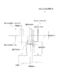
図5には、図2(B)の破線枠の領域を拡大した図を示す。図5の加工ローラ2Aは、縮径処理が終了した時点の配置を示している。図5に示すように、縮径処理により筒状部材Tの外周面は、テーパ部21aに沿って縮径する(縮径した領域を「縮径領域D」という。)。縮径領域Dに溝部Gを形成することにより、溝入れ処理時に生じる筒状部材Tの素材が溝形成部31aの両側に流れるという問題の発生を抑制することができる。よって、筒状部材の端部に溝部を形成するスピニング加工において、最終形状として開口側端部の内径を胴部の内径よりも小さくする(大きな段差を形成する)必要がある場合に好適に利用することができる。
溝部Gの形成における縮径領域Dの作用効果を鑑みると、縮径処理時における加工ローラ2Aの配置は、溝部Gの形成される範囲にテーパ部21aが配置されることが好ましい。なお、図5に示した例では、溝部Gの形成される領域の範囲内に、縮径領域Dがすべて含まれるように加工ローラ2Aを配置した例であるが、溝部Gの形成される領域に縮径領域Dが一部重複していればよい。
縮径領域Dの上端は、溝部Gの上方に配置することが好ましい。縮径領域Dの上端を溝部Gの上方に配置することにより、溝部Gと縮径領域Dの重複する領域を大きくすることができる。
縮径領域Dの下端から溝部Gの下端までの距離d1は、端面押し処理時における端面押し処理面24aの回転軸R1と平行な方向に移動する距離d2よりも大きいことが好ましい。これにより、端面押し処理時において、端面押し処理面24aが回転軸R1と平行な方向に移動した際に、テーパ部21aが筒状部材Tの外周面に当接して縮径処理が生じてしまうことを抑制することができる。
次に、図2、図5を参照して、縮径処理、溝入れ処理について説明する。
縮径処理では、図2(A)及び図5に示すように、筒状部材Tの端部の外周面を、加工ローラ2Aのテーパ部21aの小径側端部の面と、テーパ部21aの周面からなる縮径処理面24aで押圧して、筒状部材Tの端部を縮径する。筒状部材Tの端部の縮径した状態を、図5の筒状部材Tの破線により示す。図5に示すように、縮径処理の終了時には、筒状部材Tの外周面は、加工ローラ2Aの縮径処理面24aに接した状態となる。また、縮径処理では、筒状部材の厚み(外径と内径の差)を大きく変えずに、筒状部材の軸心側に径を収縮した状態となる。
縮径処理では、図2(A)及び図5に示すように、筒状部材Tの端部の外周面を、加工ローラ2Aのテーパ部21aの小径側端部の面と、テーパ部21aの周面からなる縮径処理面24aで押圧して、筒状部材Tの端部を縮径する。筒状部材Tの端部の縮径した状態を、図5の筒状部材Tの破線により示す。図5に示すように、縮径処理の終了時には、筒状部材Tの外周面は、加工ローラ2Aの縮径処理面24aに接した状態となる。また、縮径処理では、筒状部材の厚み(外径と内径の差)を大きく変えずに、筒状部材の軸心側に径を収縮した状態となる。
縮径処理は、最終製品の開口端部の外径より大きい位置で停止することが好ましい。最終製品の開口端部の外径となるまでの残りの縮径処理は、端面押し処理時又は端面押し処理後に実施する。なお、残りの縮径処理の詳細については、端面押し処理と共に後述する。
溝入れ処理では、図2(B)及び図5に示すように、縮径領域Dの位置に、溝入れ処理ローラ3の溝形成部31を筒状部材Tの外周面に進入させつつ、加工ローラ2Aの端面押部22aで筒状部材の端部の面を押圧する。縮径領域Dに溝入れ処理を行うため、筒状部材Tの素材が、溝部Gの両側の外周面に流れることを抑制し、筒状部材Tの外周面に不具合による凸部の発生を抑制することができる。また、端面押し処理により、溝部Gの形成時における回転軸R1方向への素材の流れを抑制することができるため、溝部Gの肉厚を確保することができる。
また、端面押し処理の際、図5に示すように、加工ローラ2Aは、回転軸R2の軸方向に向かって移動して、残りの縮径処理を行なう。溝入れ処理時や端面押し処理時には、筒状部材Tの開口端部の意図しない縮径が生じる場合があり、最終製品の開口端部の外径が不揃いになる恐れがある。しかし、最後の処理として、縮径処理を行なうことにより、筒状部材Tの開口端部の外径を所定の大きさに調整することができる。
端面押し処理時における加工ローラ2Aの移動は、回転軸R1の軸と平行な方向と回転軸R2に平行な方向を合成した方向に斜めに移動してもよいし、回転軸R1の軸と平行な方向への移動と回転軸R2に平行な方向への移動を別々に行ってもよい。
なお、回転軸R1の軸と平行な方向への移動と回転軸R2に平行な方向への移動を別々に行う場合には、最後に筒状部材Tの開口端部の外径を調整するという観点から、回転軸R2に平行な方向への移動を最後に停止することが好ましい。
なお、回転軸R1の軸と平行な方向への移動と回転軸R2に平行な方向への移動を別々に行う場合には、最後に筒状部材Tの開口端部の外径を調整するという観点から、回転軸R2に平行な方向への移動を最後に停止することが好ましい。
(スピニング加工方法)
本発明のスピニング加工方法は、筒状部材の端部を塑性加工するスピニング加工方法において、筒状部材の端部を縮径する縮径処理ステップと、前記端部の面を押圧する端面押し処理ステップと、を備え、前記縮径処理ステップ及び前記端面押し処理ステップを一つのローラにより行うことを特徴とするものである。
また、本発明のスピニング加工方法は、筒状部材の外周面に溝部を形成する溝入れ処理ステップを備えてもよい。
本発明のスピニング加工方法は、筒状部材の端部を塑性加工するスピニング加工方法において、筒状部材の端部を縮径する縮径処理ステップと、前記端部の面を押圧する端面押し処理ステップと、を備え、前記縮径処理ステップ及び前記端面押し処理ステップを一つのローラにより行うことを特徴とするものである。
また、本発明のスピニング加工方法は、筒状部材の外周面に溝部を形成する溝入れ処理ステップを備えてもよい。
各処理ステップの順は、最初に縮径処理ステップを行い、次いで、溝入れ処理ステップと端面押し処理ステップを行う。なお、溝入れ処理ステップと端面押し処理ステップは、同時に処理しても、別々に処理してもよい。
また、縮径処理は、2回以上に分割して行ってもよい。特に、溝入れ処理の前に行う最初の縮径処理ステップと、残りの縮径処理を行う最後の縮径処理ステップに分けることが好ましい。最初の縮径処理ステップは、溝入れ処理時における筒状部材の素材が、溝部の両側の外周面に流れることを抑制することを目的とするものである。最後の縮径処理ステップは、最終製品の開口端部の外径を調整することを目的とするものである。溝入れ処理や端面押し処理を行なうと、最終製品の開口端部の外径に多少の変化を生じる恐れがあることから、最後の縮径処理ステップは、すべての処理の最後に停止することが好ましい。
なお、縮径処理ステップだけでなく、溝入れ処理ステップ、端面押し処理ステップについても、必要に応じて2回以上に分割してもよい。
(加工ローラの形状)
図6に、本発明の加工ローラ2Aの斜視図、正面図、左側面図、右側面図を示す。なお、背面図、天面図及び底面図は、正面図と同一の形状である。本発明の加工ローラ2Aは、鋼材などの素材の塑性加工において、スピニング加工装置に取り付けて使用するための物品であり、筒状部材の端面を縮径するための縮径処理と、筒状部材の端部の面を押圧する端面押し処理を行うものである。
図6に、本発明の加工ローラ2Aの斜視図、正面図、左側面図、右側面図を示す。なお、背面図、天面図及び底面図は、正面図と同一の形状である。本発明の加工ローラ2Aは、鋼材などの素材の塑性加工において、スピニング加工装置に取り付けて使用するための物品であり、筒状部材の端面を縮径するための縮径処理と、筒状部材の端部の面を押圧する端面押し処理を行うものである。
加工ローラ2Aは、図6の正面図に示すように、加工ローラ本体23a、端面押部22a、テーパ部21aを有する。縮径処理は、円錐台状からなるテーパ部21aのテーパ周面と、テーパ部21aの小径側端部の面により実施され、端面押し処理は、円柱形状からなる端面押部の周面により実施される。すなわち、本発明の加工ローラ2Aの形状の要部は、テーパ部21aのテーパ周面から、端面押部22aの周面にまでの領域(図6の正面図に示す矢印の間の領域)である。
〔第2の実施態様〕
図7は、本発明の第2の実施態様におけるスピニング加工装置1Bの構造を示す概略説明図である。本発明の第2の実施態様におけるスピニング加工装置1Bは、図7に示すように、筒状部材Tを主軸5の先端に固定するための固定手段として、チャックからなる固定手段4Aに加え、芯棒からなる固定手段4Bを備えるものである。なお、その他の構成については、第1の実施態様のスピニング加工装置1Aを同じである。
図7は、本発明の第2の実施態様におけるスピニング加工装置1Bの構造を示す概略説明図である。本発明の第2の実施態様におけるスピニング加工装置1Bは、図7に示すように、筒状部材Tを主軸5の先端に固定するための固定手段として、チャックからなる固定手段4Aに加え、芯棒からなる固定手段4Bを備えるものである。なお、その他の構成については、第1の実施態様のスピニング加工装置1Aを同じである。
芯棒は、筒状部材Tの内径より小径の円柱状の部材であり、芯棒の一端は、筒状部材Tの内部に挿入し、筒状部材Tの底部を主軸5の先端に押し当てることにより、筒状部材Tを主軸5の先端に固定する。また、芯棒の外径を大きく設計することにより、加工された筒状部材Tの溝部の内周面を芯棒の周面により押圧することもできる。なお、芯棒の他端は、従動機構(不図示)に固定されており、芯棒は、筒状部材Tの回転と共に回転する。
この第2のスピニング加工装置1Bによれば、芯棒からなる固定手段4Bにより筒状部材Tの回転軸R1方向への固定が安定化する。そのため、端面押し処理により形成される筒状部材Tの端面の形状が平面化し、端面の形状の仕上がりに優れた製品を得ることができる。
本発明のスピニング加工装置及びスピニング加工方法は、筒状部材の端部の塑性加工のために利用することができる。より具体的には、筒状部材の端部の縮径処理のために利用することができる。例えば、ブレーキ部品(ディスクブレーキ用のブレーキピストン等)、エンジン部品、タイヤホイール、家庭用容器、装飾工芸品、照明器具、通信機器、ボイラ、タンク、ノズルなどの部品・製品の製造に利用することができる。
また、本発明のスピニング加工装置及びスピニング加工方法は、1つの加工ローラを用いて、筒状部材の端部の端面押し処理も可能であるため、縮径処理と端面押し処理を行う塑性加工において、より好適に利用することができる。
本発明の加工ローラは、スピニング加工装置に適用して、筒状部材の端部の縮径処理のために利用することができる。さらに、本発明の加工ローラは、筒状部材の端部の端面押し処理も可能であるため、縮径処理と端面押し処理を行う塑性加工において、より好適に利用することができる。
また、本発明の加工ローラは、既設のスピニング加工装置に適用することにより、縮径処理と端面押し処理をそれぞれ別のローラで行っているスピニング加工装置を、縮径処理と端面押し処理を1つの加工ローラで行うことが可能なスピニング加工装置に簡単に変更することができる。
1A,1B…スピニング加工装置、2A,2B,2C,2D,2E…加工ローラ、21a,21b,21c…テーパ部、22a,22b,22c…端面押部、23a,23b…加工ローラ本体、24a,24b…縮径処理面、25a,25b,25c…端面押し処理面、26…リム部、3…溝入れ処理ローラ、31…溝形成部、32…溝入れ処理ローラ本体、4A,4B…固定手段、5…主軸、6…加工ローラホルダ、7…溝入れ処理ローラホルダ、T…筒状部材、R1…筒状部材の回転軸、R2…加工ローラの回転軸、R3…溝入れ処理ローラの回転軸、溝部…G、縮径領域…D
Claims (5)
- スピニング加工装置において、
筒状部材の端部の縮径処理に使用する縮径処理面と、前記端部の面を押圧する端面押し処理に使用する端面押し処理面と、を有する加工ローラを備えることを特徴とする、スピニング加工装置。 - スピニング加工装置において、
筒状部材の外周面に溝部を形成する溝入れ処理ローラと、
筒状部材の端部の縮径処理に使用する縮径処理面を有する加工ローラと、を備え、
前記加工ローラの回転軸は、前記筒状部材の回転軸と略垂直に配置されることを特徴とする、スピニング加工装置。 - 前記加工ローラは、回転軸方向に縮径するテーパ部を有することを特徴とする、請求項1又は2に記載のスピニング加工装置。
- スピニング加工装置に使用する加工ローラであって、筒状部材の端部の縮径処理に使用する縮径処理面と、前記端部の面を押圧する端面押し処理に使用する端面押し処理面を有する加工ローラを備えることを特徴とする、加工ローラ。
- スピニング加工方法において、
筒状部材の端部を縮径する縮径処理ステップと、
前記端部の面を押圧する端面押し処理ステップと、を備え、
前記縮径処理ステップ及び前記端面押し処理ステップを一つのローラにより行うことを特徴とする、スピニング加工方法。
Priority Applications (1)
| Application Number | Priority Date | Filing Date | Title |
|---|---|---|---|
| CN201980074895.4A CN113195126B (zh) | 2018-12-26 | 2019-10-07 | 旋压加工装置、旋压加工方法及加工辊 |
Applications Claiming Priority (2)
| Application Number | Priority Date | Filing Date | Title |
|---|---|---|---|
| JP2018-242186 | 2018-12-26 | ||
| JP2018242186A JP7181079B2 (ja) | 2018-12-26 | 2018-12-26 | スピニング加工装置、スピニング加工方法、加工ローラ |
Publications (1)
| Publication Number | Publication Date |
|---|---|
| WO2020137077A1 true WO2020137077A1 (ja) | 2020-07-02 |
Family
ID=71129316
Family Applications (1)
| Application Number | Title | Priority Date | Filing Date |
|---|---|---|---|
| PCT/JP2019/039550 Ceased WO2020137077A1 (ja) | 2018-12-26 | 2019-10-07 | スピニング加工装置、スピニング加工方法、加工ローラ |
Country Status (3)
| Country | Link |
|---|---|
| JP (1) | JP7181079B2 (ja) |
| CN (1) | CN113195126B (ja) |
| WO (1) | WO2020137077A1 (ja) |
Cited By (1)
| Publication number | Priority date | Publication date | Assignee | Title |
|---|---|---|---|---|
| CN113894197A (zh) * | 2020-07-06 | 2022-01-07 | 日本斯频德制造株式会社 | 旋压加工装置及旋压加工方法 |
Citations (3)
| Publication number | Priority date | Publication date | Assignee | Title |
|---|---|---|---|---|
| JPH1058077A (ja) * | 1996-05-23 | 1998-03-03 | Leifeld & Co | 回転対称形状体の製造方法 |
| WO2014073258A1 (ja) * | 2012-11-12 | 2014-05-15 | 日本スピンドル製造株式会社 | 塑性加工方法及びそれに用いるスピニングマシン |
| WO2016017213A1 (ja) * | 2014-07-31 | 2016-02-04 | 日立オートモティブシステムズ株式会社 | ピストン製造装置、ピストン製造方法、ピストンおよびディスクブレーキ |
Family Cites Families (11)
| Publication number | Priority date | Publication date | Assignee | Title |
|---|---|---|---|---|
| JPS5395156A (en) * | 1977-02-01 | 1978-08-19 | Toyota Motor Corp | Rotary swaging method for hollow piston for brake |
| TW235936B (ja) * | 1992-12-18 | 1994-12-11 | Rezu Kotei Kk | |
| JP3367939B2 (ja) * | 1999-08-03 | 2003-01-20 | 株式会社三五 | 触媒コンバータの製造方法 |
| CN1535358A (zh) * | 2002-02-08 | 2004-10-06 | 株式会社丰田自动织机 | 压缩机用活塞及其制造方法 |
| JP4303457B2 (ja) * | 2002-09-30 | 2009-07-29 | 株式会社三五 | ハニカム構造体内蔵流体処理装置の製造方法 |
| CN2593928Y (zh) * | 2002-12-31 | 2003-12-24 | 华南理工大学 | 一种多功能旋压成形机床 |
| JP2007090387A (ja) * | 2005-09-29 | 2007-04-12 | Nippon Spindle Mfg Co Ltd | ブレーキピストンの製造方法 |
| JP2008126236A (ja) * | 2006-11-16 | 2008-06-05 | Nippon Spindle Mfg Co Ltd | 塑性加工方法 |
| JP5921397B2 (ja) * | 2012-09-21 | 2016-05-24 | 曙ブレーキ工業株式会社 | ブレーキ用ピストンの製造装置および製造方法 |
| JP5958967B2 (ja) * | 2013-03-26 | 2016-08-02 | 日本スピンドル製造株式会社 | 筒状素材の成形方法 |
| JP6581887B2 (ja) * | 2015-11-26 | 2019-09-25 | 日立オートモティブシステムズ株式会社 | ピストンの製造方法 |
-
2018
- 2018-12-26 JP JP2018242186A patent/JP7181079B2/ja active Active
-
2019
- 2019-10-07 WO PCT/JP2019/039550 patent/WO2020137077A1/ja not_active Ceased
- 2019-10-07 CN CN201980074895.4A patent/CN113195126B/zh not_active Expired - Fee Related
Patent Citations (3)
| Publication number | Priority date | Publication date | Assignee | Title |
|---|---|---|---|---|
| JPH1058077A (ja) * | 1996-05-23 | 1998-03-03 | Leifeld & Co | 回転対称形状体の製造方法 |
| WO2014073258A1 (ja) * | 2012-11-12 | 2014-05-15 | 日本スピンドル製造株式会社 | 塑性加工方法及びそれに用いるスピニングマシン |
| WO2016017213A1 (ja) * | 2014-07-31 | 2016-02-04 | 日立オートモティブシステムズ株式会社 | ピストン製造装置、ピストン製造方法、ピストンおよびディスクブレーキ |
Cited By (5)
| Publication number | Priority date | Publication date | Assignee | Title |
|---|---|---|---|---|
| CN113894197A (zh) * | 2020-07-06 | 2022-01-07 | 日本斯频德制造株式会社 | 旋压加工装置及旋压加工方法 |
| US20220388050A1 (en) * | 2020-07-06 | 2022-12-08 | Nihon Spindle Manufacturing Co., Ltd. | Spinning device and spinning method |
| EP4176988A4 (en) * | 2020-07-06 | 2023-12-20 | Nihon Spindle Manufacturing Co., Ltd. | SPINNING APPARATUS AND SPINNING METHOD |
| CN113894197B (zh) * | 2020-07-06 | 2024-12-24 | 日本斯频德制造株式会社 | 旋压加工装置及旋压加工方法 |
| US12186793B2 (en) * | 2020-07-06 | 2025-01-07 | Nihon Spindle Manufacturing Co., Ltd. | Spinning device and spinning method |
Also Published As
| Publication number | Publication date |
|---|---|
| JP2020104119A (ja) | 2020-07-09 |
| CN113195126B (zh) | 2024-02-13 |
| JP7181079B2 (ja) | 2022-11-30 |
| CN113195126A (zh) | 2021-07-30 |
Similar Documents
| Publication | Publication Date | Title |
|---|---|---|
| KR102426646B1 (ko) | 중공형 랙바 및 중공형 랙바를 제조하는 방법 | |
| CN104755188B (zh) | 塑性加工方法及用于该塑性加工方法的旋压装置 | |
| JP5355963B2 (ja) | パイプと被接合部材との接合方法 | |
| WO2020137077A1 (ja) | スピニング加工装置、スピニング加工方法、加工ローラ | |
| CN104001843A (zh) | 一种成型轴承圈的冷轧方法 | |
| CN102933873B (zh) | 行星滚柱螺纹传动件的螺母和用于制造这种螺母的方法 | |
| US10603705B2 (en) | Method for roll-forming disk carriers or the like and the associated profile roller set | |
| JP6641903B2 (ja) | リング状部材の製造方法 | |
| JP2019528179A (ja) | 車輪を製造するためのフロー成形機および成形方法 | |
| GB2522288A (en) | Article, method of forming an article and apparatus for forming an article | |
| KR101646363B1 (ko) | 직경이 작은 중공을 갖는 차량용 중공샤프트 제조방법 | |
| JP3127524U (ja) | 円筒体端面のセレーション成形用ローレット駒 | |
| CN109641255A (zh) | 用于由金属板圆片坯件无切削地制造旋转对称体的方法 | |
| JPS629814A (ja) | 柱状体切断装置 | |
| JP6071186B2 (ja) | 軸肥大加工装置を用いた軸肥大加工方法 | |
| JP4602060B2 (ja) | スピニングマシン | |
| JP2013240828A (ja) | スピニング加工方法、スピニング加工装置、及び成形部品 | |
| KR20150103187A (ko) | 단조 장치 및 단조 방법 | |
| JP5962529B2 (ja) | 成形方法及び成形装置 | |
| JP2007283343A (ja) | 絞り加工方法及びその装置 | |
| CN110479834A (zh) | 一种用于对轮主动强力旋压设备底板的内旋进给装置 | |
| JP2019076995A (ja) | センターツール及びその製造方法及び嵌合部品の製造方法 | |
| JP2007090387A (ja) | ブレーキピストンの製造方法 | |
| JP2020165492A (ja) | 結合構造物、結合構造物の製造方法 | |
| JP2007090373A (ja) | スピニングマシン |
Legal Events
| Date | Code | Title | Description |
|---|---|---|---|
| 121 | Ep: the epo has been informed by wipo that ep was designated in this application |
Ref document number: 19903216 Country of ref document: EP Kind code of ref document: A1 |
|
| NENP | Non-entry into the national phase |
Ref country code: DE |
|
| 122 | Ep: pct application non-entry in european phase |
Ref document number: 19903216 Country of ref document: EP Kind code of ref document: A1 |