WO2020137103A1 - Objet volant - Google Patents
Objet volant Download PDFInfo
- Publication number
- WO2020137103A1 WO2020137103A1 PCT/JP2019/040678 JP2019040678W WO2020137103A1 WO 2020137103 A1 WO2020137103 A1 WO 2020137103A1 JP 2019040678 W JP2019040678 W JP 2019040678W WO 2020137103 A1 WO2020137103 A1 WO 2020137103A1
- Authority
- WO
- WIPO (PCT)
- Prior art keywords
- motor generator
- motor
- propeller
- pcu
- engine
- Prior art date
- Legal status (The legal status is an assumption and is not a legal conclusion. Google has not performed a legal analysis and makes no representation as to the accuracy of the status listed.)
- Ceased
Links
Images






Classifications
-
- B—PERFORMING OPERATIONS; TRANSPORTING
- B64—AIRCRAFT; AVIATION; COSMONAUTICS
- B64C—AEROPLANES; HELICOPTERS
- B64C29/00—Aircraft capable of landing or taking-off vertically, e.g. vertical take-off and landing [VTOL] aircraft
- B64C29/0008—Aircraft capable of landing or taking-off vertically, e.g. vertical take-off and landing [VTOL] aircraft having its flight directional axis horizontal when grounded
- B64C29/0016—Aircraft capable of landing or taking-off vertically, e.g. vertical take-off and landing [VTOL] aircraft having its flight directional axis horizontal when grounded the lift during taking-off being created by free or ducted propellers or by blowers
-
- B—PERFORMING OPERATIONS; TRANSPORTING
- B64—AIRCRAFT; AVIATION; COSMONAUTICS
- B64D—EQUIPMENT FOR FITTING IN OR TO AIRCRAFT; FLIGHT SUITS; PARACHUTES; ARRANGEMENT OR MOUNTING OF POWER PLANTS OR PROPULSION TRANSMISSIONS IN AIRCRAFT
- B64D27/00—Arrangement or mounting of power plants in aircraft; Aircraft characterised by the type or position of power plants
- B64D27/02—Aircraft characterised by the type or position of power plants
- B64D27/30—Aircraft characterised by electric power plants
- B64D27/34—All-electric aircraft
-
- B—PERFORMING OPERATIONS; TRANSPORTING
- B64—AIRCRAFT; AVIATION; COSMONAUTICS
- B64D—EQUIPMENT FOR FITTING IN OR TO AIRCRAFT; FLIGHT SUITS; PARACHUTES; ARRANGEMENT OR MOUNTING OF POWER PLANTS OR PROPULSION TRANSMISSIONS IN AIRCRAFT
- B64D27/00—Arrangement or mounting of power plants in aircraft; Aircraft characterised by the type or position of power plants
- B64D27/02—Aircraft characterised by the type or position of power plants
- B64D27/30—Aircraft characterised by electric power plants
- B64D27/35—Arrangements for on-board electric energy production, distribution, recovery or storage
- B64D27/357—Arrangements for on-board electric energy production, distribution, recovery or storage using batteries
-
- B—PERFORMING OPERATIONS; TRANSPORTING
- B64—AIRCRAFT; AVIATION; COSMONAUTICS
- B64D—EQUIPMENT FOR FITTING IN OR TO AIRCRAFT; FLIGHT SUITS; PARACHUTES; ARRANGEMENT OR MOUNTING OF POWER PLANTS OR PROPULSION TRANSMISSIONS IN AIRCRAFT
- B64D31/00—Power plant control systems; Arrangement of power plant control systems in aircraft
- B64D31/16—Power plant control systems; Arrangement of power plant control systems in aircraft for electric power plants
-
- B—PERFORMING OPERATIONS; TRANSPORTING
- B64—AIRCRAFT; AVIATION; COSMONAUTICS
- B64U—UNMANNED AERIAL VEHICLES [UAV]; EQUIPMENT THEREFOR
- B64U50/00—Propulsion; Power supply
- B64U50/10—Propulsion
- B64U50/19—Propulsion using electrically powered motors
-
- B—PERFORMING OPERATIONS; TRANSPORTING
- B64—AIRCRAFT; AVIATION; COSMONAUTICS
- B64D—EQUIPMENT FOR FITTING IN OR TO AIRCRAFT; FLIGHT SUITS; PARACHUTES; ARRANGEMENT OR MOUNTING OF POWER PLANTS OR PROPULSION TRANSMISSIONS IN AIRCRAFT
- B64D27/00—Arrangement or mounting of power plants in aircraft; Aircraft characterised by the type or position of power plants
- B64D27/02—Aircraft characterised by the type or position of power plants
- B64D27/30—Aircraft characterised by electric power plants
- B64D27/33—Hybrid electric aircraft
-
- B—PERFORMING OPERATIONS; TRANSPORTING
- B64—AIRCRAFT; AVIATION; COSMONAUTICS
- B64D—EQUIPMENT FOR FITTING IN OR TO AIRCRAFT; FLIGHT SUITS; PARACHUTES; ARRANGEMENT OR MOUNTING OF POWER PLANTS OR PROPULSION TRANSMISSIONS IN AIRCRAFT
- B64D35/00—Transmitting power from power plants to propellers or rotors; Arrangements of transmissions
- B64D35/02—Transmitting power from power plants to propellers or rotors; Arrangements of transmissions specially adapted for specific power plants
- B64D35/021—Transmitting power from power plants to propellers or rotors; Arrangements of transmissions specially adapted for specific power plants for electric power plants
- B64D35/022—Transmitting power from power plants to propellers or rotors; Arrangements of transmissions specially adapted for specific power plants for electric power plants of hybrid-electric type
- B64D35/023—Transmitting power from power plants to propellers or rotors; Arrangements of transmissions specially adapted for specific power plants for electric power plants of hybrid-electric type of series-parallel type
-
- B—PERFORMING OPERATIONS; TRANSPORTING
- B64—AIRCRAFT; AVIATION; COSMONAUTICS
- B64U—UNMANNED AERIAL VEHICLES [UAV]; EQUIPMENT THEREFOR
- B64U10/00—Type of UAV
- B64U10/10—Rotorcrafts
-
- B—PERFORMING OPERATIONS; TRANSPORTING
- B64—AIRCRAFT; AVIATION; COSMONAUTICS
- B64U—UNMANNED AERIAL VEHICLES [UAV]; EQUIPMENT THEREFOR
- B64U30/00—Means for producing lift; Empennages; Arrangements thereof
- B64U30/20—Rotors; Rotor supports
-
- Y—GENERAL TAGGING OF NEW TECHNOLOGICAL DEVELOPMENTS; GENERAL TAGGING OF CROSS-SECTIONAL TECHNOLOGIES SPANNING OVER SEVERAL SECTIONS OF THE IPC; TECHNICAL SUBJECTS COVERED BY FORMER USPC CROSS-REFERENCE ART COLLECTIONS [XRACs] AND DIGESTS
- Y02—TECHNOLOGIES OR APPLICATIONS FOR MITIGATION OR ADAPTATION AGAINST CLIMATE CHANGE
- Y02T—CLIMATE CHANGE MITIGATION TECHNOLOGIES RELATED TO TRANSPORTATION
- Y02T50/00—Aeronautics or air transport
- Y02T50/60—Efficient propulsion technologies, e.g. for aircraft
Definitions
- the present invention relates to a flying body that propels a fuselage with a first propeller and levitates the fuselage with a second propeller.
- Japanese Unexamined Patent Application Publication No. 2016-88110 discloses that a plurality of electric motors are driven by supplying electric power from a battery to rotate a plurality of propellers and fly a multicopter.
- the multicopter of the above publication does not have fixed wings. Therefore, the operation mode of the multicopter is only the hover flight mode. As a result, when the multicopter flies, the airframe efficiency is low and a larger amount of energy is required.
- the multicopter disclosed in the above publication has a low flight speed and a short flight distance as compared with an air vehicle flying by the output of the engine. Further, when a failure of the motor or the like occurs, the multicopter cannot be flown.
- an aircraft that rotates with a motor to rotate a propeller has higher controllability than an aircraft that outputs with the output of an engine.
- an aircraft flying with the output of the motor has lower noise than an aircraft flying with the output of the engine.
- the present invention has been made in consideration of such problems, and in an optimal operating state from the viewpoint of safety, noise, comfort, controllability, and economical efficiency without making a complicated configuration. It is intended to provide a flying body that can.
- the aspect of the present invention relates to an air vehicle including a first propeller for propelling the airframe and an electrically driven second propeller for levitating the airframe.
- the aircraft includes an engine, a first motor generator connected to the engine, a second motor generator connected to the first propeller, and a clutch for connecting and disconnecting the first motor generator and the second motor generator.
- a control unit has a plurality of operation modes in which at least one of the engine, the first motor generator, and the second motor generator is used as a drive source of the first propeller.
- the control unit controls the engine, the first motor generator, the clutch, and the second motor generator in any one operation mode among a plurality of operation modes according to a state of the flying object. To do.
- the aircraft includes an engine, two motor generators (first motor generator, second motor generator), a clutch, and a controller, and at least the engine, the first motor generator, and the second motor generator.
- One is a hybrid configuration that serves as a drive source for the first propeller.
- the control unit has a plurality of operation modes, and connects and disconnects the clutch in the optimum operation mode according to the state of the flying object.
- the engine, the first motor generator, the clutch, and the second motor generator are controlled in the optimum operation mode to fly the aircraft.
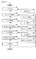
- FIG. 3 is a flowchart showing the processing of the PCU of FIG. 1.
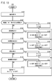
- 5 is a flowchart illustrating details of a fail mode in FIG. 4.
- 6 is a flowchart illustrating details of the engine failure mode of FIG. 5.
- 6 is a flowchart illustrating details of a first motor generator failure mode of FIG. 5.
- 6 is a flowchart illustrating details of a clutch failure mode of FIG. 5.
- 6 is a flowchart illustrating details of a clutch failure mode of FIG. 5.
- 6 is a flowchart illustrating details of a second motor generator failure mode of FIG.
- FIG. 6 is a flowchart illustrating details of a battery failure mode of FIG. 5.
- FIG. 6 is a diagram showing a list of composite fail modes in FIG. 5.
- FIG. 13 is a diagram showing an operation mode according to the double fail state of FIG. 12.
- 5 is a flowchart illustrating details of the low SOC mode of FIG. 4.
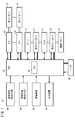
- FIG. 1 illustrates a case where the air vehicle 10 includes one propulsion propeller 12 and a plurality of levitation propellers 14.
- the flying body 10 may include at least one propulsion propeller 12 and at least one levitation propeller 14. Therefore, the present embodiment is also applicable to an aircraft including a plurality of propulsion propellers 12 and a plurality of levitation propellers 14, and an aircraft including a plurality of propulsion propellers 12 and one levitation propeller 14.
- the aircraft 10 serves as a drive mechanism for driving the propulsion propeller 12, an engine 16, a first motor generator 17 connected to the engine 16, a second motor generator 19 connected to the propulsion propeller 12, and a first motor generator 19.
- a clutch 21 that connects and disconnects the motor generator 17 and the second motor generator 19 is provided. That is, the engine 16, the first motor generator 17, the clutch 21, and the second motor generator 19 are sequentially arranged from the engine 16 toward the propeller 12.
- the flying vehicle 10 is a hybrid flying vehicle that includes two types of drive sources, the engine 16 and the two motor generators (the first motor generator 17 and the second motor generator 19) with respect to the propulsion propeller 12. Further, the flying body 10 includes a plurality of motors 24 as a drive source for rotating the plurality of levitation propellers 14.
- the engine 16 is a broad concept including various engines such as a repiro engine, a rotary engine, and a gas turbine engine.
- the air vehicle 10 further includes a body state detection sensor group 26, an environmental state detection sensor group 28, a control device 30, a PCU (power control unit) 32, an output device 34, and a battery 36.
- the airframe state detection sensor group 26 is a variety of sensors that sequentially detect the states of various detection targets included in the air vehicle 10 and output the detection results to the PCU 32.
- the sensors related to the engine 16 include the engine speed, temperature (exhaust temperature, cooling water temperature, lubricating oil temperature, fuel temperature) and pressure (cooling water pressure, hydraulic pressure, fuel pressure, in-cylinder pressure), air pressure.
- temperature exhaust temperature, cooling water temperature, lubricating oil temperature, fuel temperature
- pressure cooling water pressure, hydraulic pressure, fuel pressure, in-cylinder pressure
- the sensors related to the first motor generator 17, the second motor generator 19, and the motor 24 include various sensors that detect the rotation speed, temperature (stator temperature, magnet temperature, switching element temperature), and coil voltage and current. There is.
- sensors related to the clutch 21 there are various sensors that detect the rotation speed of the first motor generator 17 side, the rotation speed of the second motor generator 19 side, and the oil pressure of the valve that controls the clutch 21.
- SOC State Of Charge
- the environmental condition detection sensor group 28 is various sensors that detect the surrounding environment of the flying object 10, and outputs the detection result to the PCU 32.
- the environmental condition detection sensor group 28 includes, for example, various sensors that detect the outside air temperature, the altitude of the flying object 10, and the like.
- the control device 30 is a control stick or a handle for instructing the PCU 32 that the flight vehicle 10 is in a desired state (operating state, flight state) when operated by a passenger who rides on the flight vehicle 10. Therefore, the control device 30 instructs the PCU 32 about the output (necessary output, required output) required by the propulsion propeller 12 and the levitation propeller 14.
- the output device 34 is a sound output device such as a display device and a speaker, and outputs the determination result of the PCU 32 to the outside.
- the battery 36 supplies electric power to each unit of the aircraft 10 via the PCU 32.
- the battery 36 stores the generated power via the PCU 32 when at least one of the first motor generator 17 and the second motor generator 19 generates power.
- the signal flow is indicated by a thin arrow line
- the power supply flow is indicated by a thick solid line.
- the PCU 32 functions as a control unit of the aircraft 10 by executing a program stored in the memory 38 in the PCU 32. That is, the PCU 32, based on the instruction (necessary output) from the control device 30 and the detection results from the airframe state detection sensor group 26 and the environmental state detection sensor group 28, the engine 16, the first motor generator 17, the clutch 21, and the like.
- the second motor generator 19 is controlled to rotate the propeller 12 while the motor 24 is controlled to rotate the levitation propeller 14.
- the PCU 32 controls power supply from the battery 36 to each part of the aircraft 10, and storage of electricity in the battery 36 when at least one of the first motor generator 17 and the second motor generator 19 functions as a generator. To do. A specific control method will be described later.
- the PCU 32 has a plurality of operation modes regarding the propulsion propeller 12 when at least one of the engine 16, the first motor generator 17, and the second motor generator 19 is used as the drive source of the propulsion propeller 12.
- the plurality of operation modes are stored in the memory 38 in the PCU 32, for example.
- FIG. 2 shows a list of a plurality of operation modes.
- the PCU 32 (see FIG. 1) selects any one operation mode among a plurality of operation modes according to the state of the air vehicle 10, and according to the selected operation mode, the engine 16, the first motor generator 17, the clutch. 21 and the second motor generator 19 are controlled.
- the PCU 32 can grasp the state of the aircraft 10 and the required output based on the instruction from the control device 30, the detection result of the airframe state detection sensor group 26, and the detection result of the environmental state detection sensor group 28. ..
- the plurality of operation modes include an engine drive mode (hereinafter, referred to as mode A), a motor drive mode (hereinafter, referred to as mode B), an engine/motor drive mode (hereinafter, referred to as mode C), a power generation engine.
- mode A an engine drive mode
- mode B a motor drive mode
- mode C an engine/motor drive mode
- mode D a drive mode
- mode E a power generation mode
- mode F power generation/motor drive mode
- mode G stop mode
- Mode A is an operation mode in which the engine 16 directly drives the propeller 12 to obtain a flight state with high energy conversion efficiency for the propeller 12. That is, the mode A is an operation mode for realizing a highly economical flight state.
- the clutch 21 is in the connected state (ON), and the first motor generator 17 and the second motor generator 19 are in the idling state.
- the engine 16 as the drive source rotates the propulsion propeller 12 via the first motor generator 17 in the idling state, the clutch 21, and the second motor generator 19 in the idling state. Therefore, in the mode A, the first motor generator 17 and the second motor generator 19 directly transmit the output of the engine 16 to the propulsion propeller 12.
- mode B the drive of the engine 16 and the first motor generator 17 is stopped, and the propulsion propeller 12 is driven by the second motor generator 19, so that the rotation control of the propulsion propeller 12 is relatively low with relatively low noise.
- This is an operation mode for obtaining a flight state. That is, the mode B is an operation mode for realizing a flight state with high controllability and responsiveness.
- the clutch 21 is in the disengaged state (off). As a result, only the second motor generator 19 serves as a drive source to directly rotate the propulsion propeller 12.
- Mode C is an operation mode in which the engine 16, the first motor-generator 17, and the second motor-generator 19 serve as driving sources, and the propulsion propeller 12 is driven to obtain a flight state of relatively large output. is there. That is, the mode C is an operation mode for realizing a highly economical flight state.
- the clutch 21 is in the engaged state.
- the engine 16 and the first motor generator 17 rotate the propulsion propeller 12 via the clutch 21, and the second motor generator 19 directly rotates the propulsion propeller 12.
- the output of the engine 16 can be used to rotate the propeller 12 while the output of the engine 16 can be assisted by the first motor generator 17 and the second motor generator 19 depending on the required output.
- Mode D is an operation mode for obtaining a flight state in which the first motor generator 17 and the second motor generator 19 generate power while the engine 16 directly drives the propulsion propeller 12.
- the clutch 21 is in the engaged state.
- the engine 16 as a drive source rotates the propulsion propeller 12 via the clutch 21, while the output of the engine 16 causes the first motor generator 17 and the second motor generator 19 to function as a generator.
- the propulsion propeller 12 can be rotated by the output of the engine 16, while the first motor generator 17 and the second motor generator 19 can be generated according to the required output.
- Mode E is an operation mode in which the rotation of the propulsion propeller 12 is stopped, while the first motor generator 17 functions as a generator to convert all the output of the engine 16 into electric power.
- the clutch 21 is disengaged and the second motor generator 19 stops driving.
- the output of the engine 16 is not transmitted to the propeller 12 and is converted into electric power by the first motor generator 17.
- Mode F is an operation mode in which the second motor generator 19 serves as a drive source to rotate the propeller 12 while the output of the engine 16 causes the first motor generator 17 to function as a generator.
- the clutch 21 is in the disengaged state.
- the electric power generated by the first motor generator 17 can be supplied to the second motor generator 19, the second motor generator 19 can be driven by the supplied electric power, and the propeller 12 can be rotated.
- the mode G is an operation mode in which the rotation of the propulsion propeller 12 is stopped by stopping the engine 16, the first motor generator 17, and the second motor generator 19.
- the clutch 21 may be in a connected state or a disconnected state.
- a plurality of motors 24 are driven to rotate a plurality of levitation propellers 14.
- the flying body 10 levitates or hovers in the air in a low noise state.
- FIG. 3 illustrates transitions of a series of states such as landing, takeoff, forward and backward flight of the air vehicle 10 (see FIG. 1).
- the transition of the state (operating state, flight state) of the flying vehicle 10 will be mainly described, and the description of the operation of the individual constituent elements of the flying vehicle 10 will be simplified or omitted. There are cases.
- the controlling entity in this state transition diagram is the PCU 32.
- the air vehicle 10 is landing on the surface of the ground in the state of "terrestrial stop” (hereinafter also referred to as "parking").
- the transition line T1 indicates the case where the aircraft 10 is maintained in the parked state.
- the air vehicle 10 takes off from the surface of the earth and rises as shown by a transition line T2, and "takeoff". Transition to the state of. After that, the aircraft 10 rises to the target altitude by maintaining the take-off state as indicated by the transition line T3.
- the air vehicle 10 transits to the hover flight as indicated by a transition line T4.
- the PCU 32 controls each unit in the air vehicle 10 so as to maintain the speed at zero.
- the PCU 32 maintains the hover flight by controlling the roll angle, pitch angle, yaw rate, and altitude of the flying object 10.
- the flying body 10 will move to the target altitude as indicated by the transition line T6.
- the air vehicle 10 in the flight state for transitioning from hover flight to forward and backward flight (hereinafter, also referred to as transition flight).
- transition flight the air vehicle 10 remains in the state of the transition line T7. It should be noted that the flight vehicle 10 can transit from the takeoff state to the transition flight as indicated by the transition line T8.
- the flight state transits from the transition flight to the “acceleration forward/backward” flight state as indicated by a transition line T9.
- Acceleration forward/backward means moving the flying vehicle 10 forward or backward in an accelerated state at the target altitude.
- the state of the transition line T10 remains.
- transition flight In addition, when maintaining this transition flight, it stays on the transition line T20.
- the aircraft 10 transits from the transition flight to the hover flight as shown by the transition line T21, or from the transition flight as “landing” as shown by the transition line T22. Transition to the state and land from the target altitude to the surface.
- the passenger makes a transition to the hover flight and then the passenger operates the control device 30 to instruct the landing, the aircraft 10 transits from the hover flight to the “landing” state as indicated by a transition line T23. In addition, when maintaining "landing", it stays on the transition line T24.
- the air vehicle 10 When the air vehicle 10 lands on the ground surface, the air vehicle 10 transitions from the landing flight to the land stop state (parking) as indicated by a transition line T25. Further, the aircraft 10 can transition from the landing flight to the takeoff flight as indicated by a transition line T26 in accordance with the operation of the control device 30 by the passenger.
- the PCU 32 controls the plurality of motors 24 to rotate the plurality of levitation propellers 14.
- the flying body 10 is caused to fly vertically.
- the PCU 32 controls the engine 16, the first motor generator 17, the clutch 21 and the second motor generator 19. Then, the propulsion propeller 12 is rotated to make the flying body 10 fly forward and backward.
- the normal state means, for example, a state in which a failure such as a failure or an abnormality has not occurred in the flying object 10 and the SOC is equal to or higher than a threshold value.
- step S1 of FIG. 4 the PCU 32 (see FIG. 1) determines that each part of the aircraft 10 has a system error (failure) based on the detection results of the airframe state detection sensor group 26 and the environmental state detection sensor group 28. ) Is occurring.
- the system error means a failure of a detection target (for example, the engine 16) of the machine body state detection sensor group 26 and the environmental state detection sensor group 28.
- step S1 If there is a system error in step S1 (step S1: NO), proceed to the fail mode in step S2.
- step S1: NO If there is a system error in step S1 (step S1: NO), proceed to the fail mode in step S2.
- the processing in the fail mode will be described with reference to FIGS.
- step S1 YES
- the PCU 32 proceeds to step S3, and based on the detection result of the airframe state detection sensor group 26, whether or not the SOC of the battery 36 is equal to or more than the threshold value. To judge.
- step S3 NO
- the PCU 32 determines that the SOC is not sufficient, and proceeds to the low SOC mode in step S4.
- the processing in the low SOC mode will be described with reference to FIG.
- step S3 when the SOC is equal to or more than the threshold value (step S3: YES), the PCU 32 proceeds to step S5, and the instruction from the control device 30, the body state detection sensor group 26, and the environmental state detection sensor group 28 are transmitted. Based on the detection result, it is determined whether the current operating state (flight state) of the flying body 10 is takeoff, hover flight, or landing.
- step S5 if it is takeoff, hover flight, or landing (step S5: YES), the PCU 32 proceeds to step S6, selects the mode G (see FIG. 2) by referring to the memory 38, and drives the motor 24. Turn it on.
- step S5 if it is not takeoff, hover flight, or landing (step S5: NO), the PCU 32 proceeds to step S7 and determines whether or not the current flight state is transition flight.
- step S7 if the flight is a transition flight (step S7: YES), the PCU 32 proceeds to step S8, refers to the memory 38 to select the mode B, and drives the motor 24.
- step S7 if the flight is not a transition flight (step S7: NO), the PCU 32 proceeds to step S9 and determines whether or not the current flight state is acceleration forward/reverse.
- step S9 if the vehicle is in forward/backward acceleration (step S9: YES), the PCU 32 proceeds to step S10, refers to the memory 38 to select the mode C, and stops (turns off) the driving of the motor 24.
- step S9 when the vehicle is not in the forward or reverse acceleration (step S9: NO), the PCU 32 proceeds to step S11 and determines whether or not the current flight state is the forward/backward movement at a substantially constant speed.
- step S11 when the vehicle is traveling at a substantially constant speed (step S11: YES), the PCU 32 proceeds to step S12, refers to the memory 38 to select the mode A, and stops the driving of the motor 24.
- step S11 If it is determined in step S11 that the vehicle is not traveling at a substantially constant speed (step S11: NO), the PCU 32 proceeds to step S13, and determines whether or not the current flight state is deceleration/reverse traveling.
- step S13 when the vehicle is decelerating forward or backward (step S13: YES), the PCU 32 proceeds to step S14, refers to the memory 38 to select the mode D, and stops the driving of the motor 24.
- step S13 determines that the current flight state is the parking mode (the state of land stop in FIG. 3), and stores the memory 38.
- the mode G is selected with reference, and the driving of the motor 24 is stopped.
- the PCU 32 when the flying body 10 is in the normal state, the PCU 32 basically selects an appropriate operation mode from the memory 38 according to the corresponding flying state. Thereby, the PCU 32 controls the engine 16, the first motor generator 17, the clutch 21, and the second motor generator 19 to rotate the propulsion propeller 12 according to the selected operation mode, while controlling the motor 24 to levitate. Rotate the propeller 14.
- step S21 of FIG. 5 the PCU 32 (see FIG. 1) is in a single-fail state in which there is one system error such as a failure of the aircraft 10 based on the detection results of the airframe state detection sensor group 26 and the environmental state detection sensor group 28. Or not. If it is in the single fail state (step S21: YES), the process proceeds to step S22.
- step S22 the PCU 32 determines whether the single fail is a failure of the floating propeller 14. In this case, the presence/absence of failure of the levitation propeller 14 is determined based on the number of rotations of the motor 24 that drives the levitation propeller 14, temperature (stator temperature, magnet temperature, switching element temperature), and coil voltage and current.
- step S22: YES the process proceeds to step S23.
- step S23 the PCU 32 shifts to the levitation propeller failure mode, and since the levitation propeller 14 is out of order, the PCU 32 controls each part of the air vehicle 10 to land the air vehicle 10.
- step S22 determines whether the floating propeller 14 has not failed (step S22: NO). If it is determined in step S22 that the floating propeller 14 has not failed (step S22: NO), the PCU 32 proceeds to step S24 and determines whether the single fail is a failure of the engine 16. In this case, the engine speed, temperature (exhaust temperature, cooling water temperature, lubricating oil temperature, fuel temperature) and pressure (cooling water pressure, hydraulic pressure, fuel pressure, cylinder pressure), air-fuel ratio, and injector and spark plug Based on the voltage, it is determined whether the engine 16 has a failure. When the engine 16 is in failure (step S24: YES), the PCU 32 proceeds to step S25, shifts to the engine failure mode, and controls each part of the aircraft 10 according to the failure of the engine 16. Details of the engine failure mode will be described with reference to FIG.
- step S24 when the engine 16 is not in failure (step S24: NO), the PCU 32 proceeds to step S26 and determines whether the single fail is the failure of the first motor generator 17. In this case, the presence/absence of a failure in the first motor generator 17 is determined based on the rotation speed and temperature of the first motor generator 17 (stator temperature, magnet temperature, switching element temperature), and the coil voltage and current. If the first motor-generator 17 has a failure (step S26: YES), the PCU 32 proceeds to step S27, shifts to the first motor-generator failure mode, and each part of the aircraft 10 corresponding to the failure of the first motor-generator 17 is entered. Control. Details of the first motor generator failure mode will be described with reference to FIG. 7.
- step S26 determines whether the single fail is a failure of the clutch 21. In this case, the presence/absence of a failure of the clutch 21 is determined based on the rotation speed of the clutch 21 on the first motor generator 17 side, the rotation speed of the second motor generator 19 side, and the oil pressure of the valve that controls the clutch 21.
- step S28 determines whether the clutch 21 is in failure (step S28: YES)
- step S29 shifts to the clutch failure mode, and controls each part of the aircraft 10 according to the failure of the clutch 21. Details of the clutch failure mode will be described with reference to FIGS. 8 and 9.
- step S28 if the clutch 21 is not in failure (step S28: NO), the PCU 32 proceeds to step S30 and determines whether or not the single fail is in the second motor generator 19. In this case, the presence/absence of a failure of the second motor generator 19 is determined based on the rotation speed and temperature of the second motor generator 19 (stator temperature, magnet temperature, switching element temperature), and the coil voltage and current. If the second motor generator 19 is in failure (step S30: YES), the PCU 32 proceeds to step S31 and shifts to the second motor generator failure mode, where each part of the aircraft 10 responds to the failure in the second motor generator 19. Control. Details of the second motor generator failure mode will be described with reference to FIG.
- step S30 the PCU 32 proceeds to step S32, determines that the single fail is the failure of the battery 36, shifts to the battery failure mode, and the battery failure mode is set. The control of each unit of the aircraft 10 according to the failure of 36 is performed. Details of the battery failure mode will be described with reference to FIG.
- the PCU 32 may determine the failure of the battery 36 based on the SOC, voltage, temperature, etc. of the battery 36.
- step S21 determines that it is a combined fail of abnormalities or failures at two or more places, and proceeds to step S33.
- step S33 the PCU 32 shifts to the composite fail mode and controls each part of the aircraft 10 according to the failure at a plurality of locations. Details of the composite fail mode will be described with reference to FIGS. 12 and 13.
- step S41 of FIG. 6 the PCU 32 (see FIG. 1) notifies the outside that the engine 16 is out of order via the output device 34.
- the output device 34 is a display device
- the fact that the engine 16 is out of order is displayed on the screen of the display device to warn the passenger.
- step S42 the PCU 32 determines whether the current operating state (flight state) of the flying vehicle 10 is takeoff, hover flight, or landing. In the case of takeoff, hover flight, or landing (step S42: YES), the PCU 32 proceeds to step S43, refers to the memory 38 to select the mode G (see FIG. 2), and drives (turns on) the motor 24. ..
- step S42 When it is not takeoff, hover flight, or landing in step S42 (step S42: NO), the PCU 32 proceeds to step S44 to detect an instruction from the control device 30 and the airframe state detection sensor group 26 and the environmental state detection sensor group 28. Based on the result, it is determined whether the current flight state is transition flight.
- step S44 if the flight is a transition flight (step S44: YES), the PCU 32 proceeds to step S45, refers to the memory 38 to select the mode B, and drives the motor 24.
- step S44 if the flight is not a transition flight (step S44: NO), the PCU 32 proceeds to step S46, and the current flight state is various forward/backward movements (acceleration forward/backward movement, approximately constant speed forward/backward movement or deceleration forward/backward movement). Or not.
- step S46 if either forward or reverse is being performed (step S46: YES), the PCU 32 proceeds to step S47, refers to the memory 38 to select the mode B, and stops (turns off) the driving of the motor 24. ..
- step S46 determines that the current flight state is the parking mode (state of land stop in FIG. 3), and the memory 38 , The mode G is selected, and the driving of the motor 24 is stopped.
- the PCU 32 drives the second motor generator 19 to rotate the propeller 12 during transition flight or various forward/backward movements (steps S45, S47). Mode B). Thereby, the PCU 32 can control the clutch 21 to rotate the propulsion propeller 12 while controlling the motor 24 to rotate the levitation propeller 14 according to the selected operation mode.
- step S51 in FIG. 7 the PCU 32 (see FIG. 1) notifies the outside (warning display) of the failure of the first motor generator 17 via the output device 34.
- step S52 the PCU 32 determines whether the current operating state (flight state) of the flying body 10 is takeoff, hover flight, or landing. In the case of takeoff, hover flight, or landing (step S52: YES), the PCU 32 proceeds to step S53, selects the mode G (see FIG. 2) with reference to the memory 38, and drives (turns on) the motor 24. ..
- step S52 if it is not takeoff, hover flight, or landing (step S52: NO), the PCU 32 proceeds to step S54 to detect an instruction from the control device 30 and the airframe state detection sensor group 26 and the environmental state detection sensor group 28. Based on the result, it is determined whether the current flight state is transition flight.
- step S54 if the flight is a transition flight (step S54: YES), the PCU 32 proceeds to step S55, refers to the memory 38 to select the mode B, and drives the motor 24.
- step S54 if the flight is not a transition flight (step S54: NO), the PCU 32 proceeds to step S56 and determines whether or not the current flight state is acceleration forward/reverse.
- step S56 when the vehicle is in forward/backward acceleration (step S56: YES), the PCU 32 proceeds to step S57, refers to the memory 38 to select the mode C, and stops (turns off) the driving of the motor 24. That is, since the first motor generator 17 is out of order, the second motor generator 19 is driven to rotate the propulsion propeller 12.
- step S56 if the vehicle is not accelerating forward/backward (step S56: NO), the PCU 32 proceeds to step S58 and determines whether or not the current flight condition is approximately constant speed forward/reverse traveling.
- step S58 when the vehicle is traveling at a substantially constant speed (step S58: YES), the PCU 32 proceeds to step S59, refers to the memory 38 to select the mode A, and stops the driving of the motor 24.
- the first motor generator 17 in the failed state is in the idling state and transmits the output of the engine 16 as it is to the second motor generator 19 side.
- step S58 If it is determined in step S58 that the vehicle is not traveling at a substantially constant speed (step S58: NO), the PCU 32 proceeds to step S60 and determines whether or not the current flight state is deceleration/reverse traveling.
- step S60 when the vehicle is decelerating forward or backward (step S60: YES), the PCU 32 proceeds to step S61, refers to the memory 38 to select the mode D, and stops the driving of the motor 24.
- the first motor-generator 17 in the failure state is in the idling state, the output of the engine 16 is transmitted to the second motor-generator 19 side as it is, and only the second motor-generator 19 generates power.
- step S60 If the vehicle is not decelerating forward or backward in step S60 (step S60: NO), the PCU 32 proceeds to step S62, determines that the current flight state is the parking mode, selects the mode G with reference to the memory 38, and , The drive of the motor 24 is stopped.
- the PCU 32 drives the engine 16 or the second motor generator 19 to rotate the propulsion propeller 12 during transition flight or various forward/backward movements.
- Modes B, C, A, and D in steps S55, S57, S59, and S61).
- the PCU 32 can control the clutch 21 to rotate the propulsion propeller 12 while controlling the motor 24 to rotate the levitation propeller 14 according to the selected operation mode.
- step S71 of FIG. 8 is the PCU 32 (see FIG. 1) a malfunction of the clutch 21 (a malfunction (ON malfunction)) in which the connected state is maintained even when the PCU 32 instructs the clutch 21 to disconnect. Determine whether or not.
- step S71: YES the PCU 32 proceeds to step S72 and notifies the passenger (warning display) that the clutch 21 is on-failure through the output device 34.
- step S73 the PCU 32 determines whether the current operating state (flight state) of the flying object 10 is takeoff, hover flight, or landing. In the case of takeoff, hover flight, or landing (step S73: YES), the PCU 32 proceeds to step S74 and refers to the memory 38 to select mode G (see FIG. 2) and drives (turns on) the motor 24. ..
- step S73 if it is not takeoff, hover flight, or landing (step S73: NO), the PCU 32 proceeds to step S75, detects an instruction from the control device 30, and detects the airframe state detection sensor group 26 and the environmental state detection sensor group 28. Based on the result, it is determined whether the current flight state is transition flight.
- step S75 if the flight is a transition flight (step S75: YES), the PCU 32 proceeds to step S76, refers to the memory 38 to select the mode C, and drives the motor 24.
- step S75 if the flight is not a transition flight (step S75: NO), the PCU 32 proceeds to step S77 and determines whether or not the current flight state is acceleration forward/reverse.
- step S77 if the vehicle is accelerating forward or backward (step S77: YES), the PCU 32 proceeds to step S78 to refer to the memory 38 to select the mode C and stop (turn off) the driving of the motor 24.
- step S77 if the vehicle is not in acceleration/reverse movement (step S77: NO), the PCU 32 proceeds to step S79 to determine whether or not the current flight state is substantially constant speed forward/reverse movement.
- step S79 when the vehicle is traveling at a substantially constant speed (step S79: YES), the PCU 32 proceeds to step S80, refers to the memory 38 to select the mode A, and stops the driving of the motor 24.
- step S79 If it is determined in step S79 that the vehicle is not traveling at a substantially constant speed (step S79: NO), the PCU 32 proceeds to step S81 and determines whether or not the current flight state is deceleration/reverse traveling.
- step S81 if the vehicle is decelerating forward or backward (step S81: YES), the PCU 32 proceeds to step S82, refers to the memory 38 to select the mode D, and stops driving the motor 24.
- step S81 determines that the current flight state is the parking mode, selects the mode G with reference to the memory 38, and , The drive of the motor 24 is stopped.
- the PCU 32 rotates the propulsion propeller 12 in the operation mode using the output of the engine 16 during the transition flight or various forward and backward movements, or the first motor.
- the generator 17 and the second motor generator 19 are caused to generate power (modes C, A and D in steps S76, S78, S80 and S82).
- the PCU 32 controls the engine 16, the first motor generator 17, and the second motor generator 19 to rotate the propulsion propeller 12 according to the selected operation mode, while controlling the motor 24 to control the levitation propeller 14. Can be rotated.
- step S71 if the failure of the clutch 21 is a failure (off failure) that does not shift to the connected state even if the PCU 32 instructs the clutch 21 to connect (step S71: NO), step S91 of FIG. Proceed to.
- step S91 the PCU 32 (see FIG. 1) informs the passenger via the output device 34 (warning display) that the clutch 21 is off.
- step S92 the PCU 32 determines whether the current operating state (flight state) of the flying vehicle 10 is takeoff, hover flight, or landing. In the case of takeoff, hover flight, or landing (step S92: YES), the PCU 32 proceeds to step S93 to refer to the memory 38 to select the mode G (see FIG. 2) and drive (turn on) the motor 24. ..
- step S92 If it is not takeoff, hover flight, or landing in step S92 (step S92: NO), the PCU 32 proceeds to step S94 to detect an instruction from the control device 30 and the airframe state detection sensor group 26 and the environmental state detection sensor group 28. Based on the result, it is determined whether the current flight state is transition flight.
- step S94 if the flight is a transition flight (step S94: YES), the PCU 32 proceeds to step S95, refers to the memory 38 to select the mode B, and drives the motor 24.
- step S94 if the flight is not a transition flight (step S94: NO), the PCU 32 proceeds to step S96 and determines whether or not the current flight state is various forward/backward movements.
- step S96 if the vehicle is moving in various directions (step S96: YES), the PCU 32 proceeds to step S97, refers to the memory 38 to select the mode B, and stops (turns off) the driving of the motor 24.
- step S96 when the vehicle is not moving in the various directions (step S96: NO), the PCU 32 proceeds to step S98, determines that the current flight state is the parking mode, and refers to the memory 38 to select the mode G. At the same time, the driving of the motor 24 is stopped.
- the PCU 32 rotates the propulsion propeller 12 in the operation mode using the output of the second motor generator 19 during transition flight or various forward and backward movements (step S95). , Mode B of S97). Even in this case, the PCU 32 can control the second motor generator 19 to rotate the propulsion propeller 12 while controlling the motor 24 to rotate the levitation propeller 14 according to the selected operation mode.
- step S101 of FIG. 10 the PCU 32 (see FIG. 1) notifies the outside (warning display) of the failure of the second motor generator 19 via the output device 34.
- step S102 the PCU 32 determines whether the current operating state (flight state) of the flying object 10 is takeoff, hover flight, or landing. In the case of takeoff, hover flight, or landing (step S102: YES), the PCU 32 proceeds to step S103, selects the mode G (see FIG. 2) by referring to the memory 38, and drives (turns on) the motor 24. ..
- step S102 if it is not takeoff, hover flight, or landing (step S102: NO), the PCU 32 proceeds to step S104 to detect an instruction from the control device 30 and the airframe state detection sensor group 26 and the environmental state detection sensor group 28. Based on the result, it is determined whether the current flight state is transition flight.
- step S104 if the flight is a transition flight (step S104: YES), the PCU 32 proceeds to step S105, refers to the memory 38 to select the mode C, and drives the motor 24.
- step S105 refers to the memory 38 to select the mode C, and drives the motor 24.
- the second motor generator 19 in the failed state becomes idling and transmits the outputs of the engine 16 and the first motor generator 17 to the propulsion propeller 12 as they are.
- step S104 if the flight is not a transition flight (step S104: NO), the PCU 32 proceeds to step S106, and determines whether or not the current flight state is acceleration forward/reverse.
- step S106 if the vehicle is in forward/backward acceleration (step S106: YES), the PCU 32 proceeds to step S107, refers to the memory 38 to select the mode C, and stops (turns off) the driving of the motor 24. Also in this case, similarly to step S105, the second motor generator 19 in the failed state is in the idling state and transmits the outputs of the engine 16 and the first motor generator 17 to the propulsion propeller 12 as they are.
- step S106 if the vehicle is not in the forward/backward acceleration (step S106: NO), the PCU 32 proceeds to step S108 to determine whether or not the current flight state is a substantially constant speed forward/backward movement.
- step S108 when the vehicle is traveling at a substantially constant speed (step S108: YES), the PCU 32 proceeds to step S109, refers to the memory 38 to select the mode A, and stops the driving of the motor 24.
- step S109 refers to the memory 38 to select the mode A, and stops the driving of the motor 24.
- both the first motor generator 17 and the second motor generator 19 are in the idling state, and the output of the engine 16 is transmitted to the propulsion propeller 12 as it is.
- step S108 If it is determined in step S108 that the vehicle is not traveling at a substantially constant speed (step S108: NO), the PCU 32 proceeds to step S110 to determine whether or not the current flight state is deceleration/reverse traveling.
- step S110 when the vehicle is decelerating forward or backward (step S110: YES), the PCU 32 proceeds to step S111, refers to the memory 38 to select the mode D, and stops the driving of the motor 24.
- the second motor generator 19 in the failed state is in the idling state and transmits the output of the engine 16 to the propulsion propeller 12 as it is.
- step S110: NO the PCU 32 proceeds to step S112, determines that the current flight state is the parking mode, selects the mode G with reference to the memory 38, and , The drive of the motor 24 is stopped.
- the PCU 32 drives the engine 16 to rotate the propulsion propeller 12 during transition flight or various forward/backward movements (steps S109 and S111).
- Mode A, D or whether the engine 16 and the first motor generator 17 are driven to rotate the propeller 12 (mode C in steps S105 and S107).
- the PCU 32 can control the clutch 21 to rotate the propulsion propeller 12 while controlling the motor 24 to rotate the levitation propeller 14 according to the selected operation mode.
- step S121 of FIG. 11 the PCU 32 (see FIG. 1) notifies the outside (warning display) of the failure of the battery 36 via the output device 34.
- step S122 the PCU 32 determines whether the current operating state (flight state) of the flying body 10 is takeoff, hover flight, or transition flight from vertical flight to forward/backward travel. In the case of takeoff, hover flight, or the above-mentioned transition flight (step S122: YES), the PCU 32 proceeds to step S123, shifts to the landing mode, and makes the aircraft 10 land.
- step S122 if it is not takeoff, hover flight, or the above-mentioned transition flight (step S122: NO), the PCU 32 proceeds to step S124, and issues an instruction from the control device 30, the airframe state detection sensor group 26, and the environmental state detection. Based on the detection result of the sensor group 28, it is determined whether or not the current flight state is various forward/rearward travels.
- step S124 when the vehicle is moving in various directions (step S124: YES), the PCU 32 proceeds to step S125, refers to the memory 38 to select the mode A (see FIG. 2), and stops driving the motor 24. To do.
- step S124 if it is not various forward and backward movements (step S124: NO), the PCU 32 proceeds to step S126 to determine whether or not the current flight state is a transitional flight from forward or backward movement to vertical flight.
- step S126 in the case of the above-mentioned transition flight (step S126: YES), the PCU 32 proceeds to step S127, refers to the memory 38 to select the mode D, and drives the motor 24.
- step S126 If it is not the above-mentioned transition flight in step S126 (step S126: NO), the PCU 32 proceeds to step S128 and determines whether or not the current operating state is landing.
- step S128 if the vehicle is landing (step S128: YES), the PCU 32 proceeds to step S129, refers to the memory 38 to select the mode E, and drives the motor 24.
- step S128 If it is not landing in step S128 (step S128: NO), the PCU 32 proceeds to step S130, determines that the current flight state is the parking mode, selects the mode G by referring to the memory 38, and selects the motor G. The driving of 24 is stopped.
- the PCU 32 controls the motor 24 to rotate the levitation propeller 14.
- the first motor generator 17 or the second motor generator 19 is generated by the output of the engine 16, and the generated power is supplied to the motor 24 to drive the motor 24 (modes D and E in steps S127 and S129).
- the PCU 32 can control the clutch 21 to rotate the propulsion propeller 12 while controlling the motor 24 to rotate the levitation propeller 14 according to the selected operation mode.
- the PCU 32 preferentially selects the operation mode corresponding to the previously determined double failure, or The operation mode with the higher safety is selected from the double failures.
- priorities are determined in the columns and rows of the table, and when different double failures are detected before and after the time, the higher priority double failures are detected.
- Different operating modes may be selected. For example, when the occurrence of two double fails of (1) and (2) in FIG. 12 is detected, the PCU 32 selects the double fail of (1) having a high priority and selects the selected one of (1). Select the operation mode according to double fail.
- the operation mode is selected by a method different from the single fail mode described with reference to FIGS. 6 to 11.
- step S131 of FIG. 14 the PCU 32 (see FIG. 1) informs the passenger via the output device 34 (warning display) that the SOC is relatively low.
- step S132 the PCU 32 determines whether the current operating state (flight state) of the flying body 10 is takeoff, hover flight, or landing. In the case of takeoff, hover flight, or landing (step S132: YES), the PCU 32 proceeds to step S133, selects the mode E (see FIG. 2) by referring to the memory 38, and drives (turns on) the motor 24. ..
- step S132 if it is not takeoff, hover flight, or landing (step S132: NO), the PCU 32 proceeds to step S134 to detect an instruction from the control device 30 and the airframe state detection sensor group 26 and the environmental state detection sensor group 28. Based on the result, it is determined whether the current flight state is transition flight.
- step S134 if the flight is a transition flight (step S134: YES), the PCU 32 proceeds to step S135, refers to the memory 38 to select the mode F, and drives the motor 24.
- step S134 if the flight is not a transition flight (step S134: NO), the PCU 32 proceeds to step S136 and determines whether or not the current flight state is acceleration forward/reverse.
- step S136 when the vehicle is in forward or backward acceleration (step S136: YES), the PCU 32 proceeds to step S137, refers to the memory 38 to select the mode A, and stops (turns off) the driving of the motor 24.
- step S136 if the vehicle is not in the forward/backward acceleration (step S136: NO), the PCU 32 proceeds to step S138 and determines whether or not the current flight state is the forward/backward traveling at a substantially constant speed or the forward/backward deceleration.
- step S138 when the vehicle is traveling at a substantially constant speed in the forward/rearward direction or in the decelerating forward/backward direction (step S138: YES), the PCU 32 proceeds to step S139 to select the mode D by referring to the memory 38 and drive the motor 24. Stop.
- step S138 determines that the current flight state is the parking mode, and refers to the memory 38.
- the mode E is selected by using the control mode and the driving of the motor 24 is stopped.
- the PCU 32 prioritizes the power storage in the battery 36 or the power supply to the motor 24, so that the first motor generator 17 or the second motor generator 19 is driven by the output of the engine 16. Power is generated (modes E, F, and D in steps S133, S135, S139, and S140). At that time, the PCU 32 stores, in the battery 36, the surplus electric power obtained by subtracting the electric power required for the motor 24 to rotate the levitation propeller 14 from the electric power generated by the first motor generator 17 or the second motor generator 19. To do. On the other hand, when the amount of electric power generated by the first motor generator 17 or the second motor generator 19 cannot cover the amount of electric power required by the motor 24, the battery 36 supplies insufficient power to the motor 24. Even in this case, the PCU 32 controls the engine 16, the first motor generator 17, the clutch 21, and the second motor generator 19 to rotate the propulsion propeller 12 according to the selected operation mode, while controlling the motor 24. The levitation propeller 14 can be rotated.
- the aircraft 10 includes the propulsion propeller 12 (first propeller) that propels the aircraft and the electric levitation propeller 14 (second propeller) that levitates the aircraft.
- the aircraft 10 disconnects the engine 16, the first motor generator 17 connected to the engine 16, the second motor generator 19 connected to the propulsion propeller 12, and the first motor generator 17 and the second motor generator 19.
- the clutch 21 and the PCU 32 (control part) which contact are further provided.
- the PCU 32 has a plurality of operation modes in which at least one of the engine 16, the first motor generator 17, and the second motor generator 19 is used as the drive source of the propulsion propeller 12.
- the PCU 32 controls the engine 16, the first motor-generator 17, the clutch 21, and the second motor-generator 19 in any one operation mode among a plurality of operation modes according to the state of the aircraft 10.
- the aircraft 10 includes the engine 16, the two motor generators (the first motor generator 17, the second motor generator 19), the clutch 21, and the PCU 32, and the engine 16, the first motor generator 17, and the second motor generator 17 are provided.
- At least one of the motor generators 19 has a hybrid configuration that serves as a drive source for the propulsion propeller 12.
- the PCU 32 has a plurality of operation modes, and connects and disconnects the clutch 21 in an optimum operation mode according to the state of the flying vehicle 10.
- the engine 16 the first motor generator 17, the clutch 21, and the second motor generator 19 are controlled in the optimum operation mode, and You can fly 10.
- the flying body 10 it is possible to realize the flying body 10 with a high degree of freedom of control that can cope with various situations without having a complicated configuration.
- the aircraft 10 further includes a motor 24 as a drive source of the levitation propeller 14 and a battery 36 that supplies electric power to each part of the aircraft 10.
- the PCU 32 selects any one operation mode among a plurality of operation modes based on at least one of the presence/absence of a failure of the flying object 10 and the SOC of the battery 36, and in the selected operation mode, the engine is selected. 16, the first motor generator 17, the clutch 21, and the second motor generator 19 are controlled, while the motor 24 is controlled. In this way, the optimum operation mode can be selected according to the presence/absence of fail and the SOC. As a result, especially under normal conditions, noise can be reduced and comfort and economy can be improved.
- the PCU 32 controls the motor 24 when the aircraft 10 takes off, hovers, or lands. Then, the floating propeller 14 is rotated. As a result, it is possible to reduce noise and further improve comfort and economy.
- the PCU 32 controls the motor 24 to rotate the levitation propeller 14 during the transition flight in which the flying body 10 takes off, hovers, or transitions between landing and forward/backward flight.
- the clutch 21 is disengaged and the second motor generator 19 is controlled to rotate the propulsion propeller 12.
- the PCU 32 disengages the clutch 21 and causes the first motor generator 17 to generate power by the output of the engine 16 when the flying object 10 takes off, hovers, or lands.
- the floating propeller 14 is rotated by supplying the generated electric power to the motor 24.
- the PCU 32 causes the clutch 21 to be disengaged and causes the first motor generator 17 to generate electric power by the output of the engine 16 when the flying object 10 makes a transition flight, and the generated electric power is generated.
- the levitation propeller 14 is rotated, and at the same time, the second motor generator 19 is controlled to rotate the propulsion propeller 12.
- the PCU 32 stores, in the battery 36, surplus electric power obtained by subtracting at least the electric power required for the rotation of the levitation propeller 14 from the electric power generated by the first motor generator 17, while the first motor generator 17 is stored.
- the deficient electric power is supplied from the battery 36 to the levitation propeller 14. This makes it possible to appropriately supply electric power to each unit of the flying vehicle 10 while ensuring the SOC of the battery 36.
- the PCU 32 sets the clutch 21 in the engaged state and rotates the propulsion propeller 12 by the output of the engine 16 when the flying body 10 travels forward and backward.
- the output of the engine 16 is assisted by the first motor generator 17 and the second motor generator 19, or the first motor generator 17 and the second motor generator 19 are operated. Generate electricity. In this way, hybrid operation according to the presence/absence of a fail or SOC becomes possible, so that it is possible to reduce power consumption of the battery 36, reduce noise, and improve comfort and economy at once.
- the PCU 32 gives priority to the continuation of the flight of the flying object 10, and therefore, among the plurality of operation modes, a fail mode (another failure mode different from the operation mode in the normal state).
- the operation mode is selected, and the engine 16, the first motor generator 17, the clutch 21, and the second motor generator 19 are controlled in the selected fail mode.
- the redundant operation mode is selected, so that the safety of the aircraft 10 can be enhanced.
- the PCU 32 selects and selects another combined fail operation mode different from the single fail operation mode when one failure occurs.
- the engine 16, the first motor generator 17, the clutch 21, and the second motor generator 19 are controlled in the operation mode of the composite fail. In this way, when a plurality of failures have occurred, the safety of the aircraft 10 can be further enhanced by selecting a redundant operation mode.
Landscapes
- Engineering & Computer Science (AREA)
- Aviation & Aerospace Engineering (AREA)
- Chemical & Material Sciences (AREA)
- Combustion & Propulsion (AREA)
- Hybrid Electric Vehicles (AREA)
- Mechanical Engineering (AREA)
- Electric Propulsion And Braking For Vehicles (AREA)
Abstract
L'invention concerne un objet volant (10), dans lequel une PCU (32) a une pluralité de modes de fonctionnement dans lesquels un moteur (16) et/ou un premier moteur-générateur (17) et/ou un second moteur-générateur (19) est utilisé comme source d'entraînement pour une hélice-poussoir (12). En fonction de l'état de l'objet volant (10), la PCU (32) commande le moteur (16), le premier moteur-générateur (17), un embrayage (21) et le second moteur-générateur (19) dans l'un des modes de fonctionnement.
Priority Applications (1)
| Application Number | Priority Date | Filing Date | Title |
|---|---|---|---|
| US17/312,955 US20220055743A1 (en) | 2018-12-27 | 2019-10-16 | Flying object |
Applications Claiming Priority (2)
| Application Number | Priority Date | Filing Date | Title |
|---|---|---|---|
| JP2018244575 | 2018-12-27 | ||
| JP2018-244575 | 2018-12-27 |
Publications (1)
| Publication Number | Publication Date |
|---|---|
| WO2020137103A1 true WO2020137103A1 (fr) | 2020-07-02 |
Family
ID=71126277
Family Applications (1)
| Application Number | Title | Priority Date | Filing Date |
|---|---|---|---|
| PCT/JP2019/040678 Ceased WO2020137103A1 (fr) | 2018-12-27 | 2019-10-16 | Objet volant |
Country Status (2)
| Country | Link |
|---|---|
| US (1) | US20220055743A1 (fr) |
| WO (1) | WO2020137103A1 (fr) |
Cited By (3)
| Publication number | Priority date | Publication date | Assignee | Title |
|---|---|---|---|---|
| GB2613631A (en) * | 2021-12-10 | 2023-06-14 | Epropelled Ltd | Aircraft electric propulsion |
| WO2023189644A1 (fr) * | 2022-03-29 | 2023-10-05 | 株式会社石川エナジーリサーチ | Dispositif de vol et procédé de commande de dispositif de vol |
| DE102021204525B4 (de) * | 2020-11-06 | 2026-05-07 | Hyundai Motor Company | Hybrid-luftmobilitätsfahrzeug |
Families Citing this family (1)
| Publication number | Priority date | Publication date | Assignee | Title |
|---|---|---|---|---|
| US12565325B1 (en) * | 2024-12-30 | 2026-03-03 | Pratt & Whitney Canada Corp. | Propulsor reverse rotation protection for hybrid-electric aircraft propulsion systems |
Citations (3)
| Publication number | Priority date | Publication date | Assignee | Title |
|---|---|---|---|---|
| US20170029131A1 (en) * | 2015-07-29 | 2017-02-02 | Airbus Defence and Space GmbH | Hybrid Electric Drive Train For VTOL Drones |
| CN207826569U (zh) * | 2018-01-29 | 2018-09-07 | 吉林大学 | 一种固定翼式混合动力飞行器驱动装置 |
| JP2018140767A (ja) * | 2016-12-13 | 2018-09-13 | ゼネラル・エレクトリック・カンパニイ | ハイブリッド電気駆動システム |
Family Cites Families (8)
| Publication number | Priority date | Publication date | Assignee | Title |
|---|---|---|---|---|
| WO2006113877A2 (fr) * | 2005-04-20 | 2006-10-26 | Lugg Richard H | Aeronef vtol hybride a reaction/electrique |
| US20120209456A1 (en) * | 2011-02-15 | 2012-08-16 | Government Of The United States, As Represented By The Secretary Of The Air Force | Parallel Hybrid-Electric Propulsion Systems for Unmanned Aircraft |
| DE102012021339A1 (de) * | 2012-10-31 | 2014-04-30 | Eads Deutschland Gmbh | Unbemanntes Luftfahrzeug und Betriebsverfahren hierfür |
| US10822101B2 (en) * | 2017-07-21 | 2020-11-03 | General Electric Company | Vertical takeoff and landing aircraft having a forward thrust propulsor |
| US20190118943A1 (en) * | 2017-10-24 | 2019-04-25 | General Atomics Aeronautical Systems, Inc. | Tail-Sitter Aircraft With Hybrid Propulsion |
| US20190256202A1 (en) * | 2018-02-19 | 2019-08-22 | Parallel Flight Technologies, Inc. | Method and apparatus for lifting a payload |
| FR3087421B1 (fr) * | 2018-10-17 | 2022-03-04 | Voltaero | Engin comprenant un groupe motopropulseur hybride et procede de pilotage correspondant |
| US10759540B2 (en) * | 2018-11-08 | 2020-09-01 | Rolls-Royce North American Technologies, Inc. | Hybrid propulsion systems |
-
2019
- 2019-10-16 US US17/312,955 patent/US20220055743A1/en not_active Abandoned
- 2019-10-16 WO PCT/JP2019/040678 patent/WO2020137103A1/fr not_active Ceased
Patent Citations (3)
| Publication number | Priority date | Publication date | Assignee | Title |
|---|---|---|---|---|
| US20170029131A1 (en) * | 2015-07-29 | 2017-02-02 | Airbus Defence and Space GmbH | Hybrid Electric Drive Train For VTOL Drones |
| JP2018140767A (ja) * | 2016-12-13 | 2018-09-13 | ゼネラル・エレクトリック・カンパニイ | ハイブリッド電気駆動システム |
| CN207826569U (zh) * | 2018-01-29 | 2018-09-07 | 吉林大学 | 一种固定翼式混合动力飞行器驱动装置 |
Cited By (6)
| Publication number | Priority date | Publication date | Assignee | Title |
|---|---|---|---|---|
| DE102021204525B4 (de) * | 2020-11-06 | 2026-05-07 | Hyundai Motor Company | Hybrid-luftmobilitätsfahrzeug |
| GB2613631A (en) * | 2021-12-10 | 2023-06-14 | Epropelled Ltd | Aircraft electric propulsion |
| WO2023189644A1 (fr) * | 2022-03-29 | 2023-10-05 | 株式会社石川エナジーリサーチ | Dispositif de vol et procédé de commande de dispositif de vol |
| JP2023146695A (ja) * | 2022-03-29 | 2023-10-12 | 株式会社石川エナジーリサーチ | 飛行装置 |
| US12441495B2 (en) | 2022-03-29 | 2025-10-14 | Ishikawa Energy Research Co., Ltd. | Flight device and flight device control method |
| JP7838755B2 (ja) | 2022-03-29 | 2026-04-01 | 株式会社石川エナジーリサーチ | 飛行装置 |
Also Published As
| Publication number | Publication date |
|---|---|
| US20220055743A1 (en) | 2022-02-24 |
Similar Documents
| Publication | Publication Date | Title |
|---|---|---|
| WO2020137105A1 (fr) | Objet volant | |
| US12134469B2 (en) | Vertical take-off and landing aircraft using hybrid-electric propulsion system and the control method | |
| EP3318492B1 (fr) | Système propulsif turboélectrique réparti ac et dc combiné | |
| WO2020137104A1 (fr) | Objet volant | |
| KR101501978B1 (ko) | 항공기용 하이브리드 구동 및 에너지 시스템 | |
| US20130099065A1 (en) | Tilt-wing aircraft | |
| US20210094694A1 (en) | Electric motor for a propeller engine | |
| US20220055743A1 (en) | Flying object | |
| JP7810590B2 (ja) | 制御システム及び制御方法並びに航空機 | |
| US12552524B2 (en) | Method and device for controlling a thermal and electrical power plant for a rotorcraft | |
| AU2021399186B2 (en) | Airship equipped with an electric distributed propulsion system | |
| WO2015075538A1 (fr) | Corps mobile | |
| US20200324908A1 (en) | Electric drive system for an aircraft with a minimal yawing moment | |
| WO2020250029A1 (fr) | Procédé et aéronef convertible vtol ou evtol pour transition d'un mode hélicoptère à un mode autogire et vice versa | |
| CN118529255A (zh) | 一种混合动力系统及控制方法 | |
| US12296966B2 (en) | Aircraft | |
| KR102279741B1 (ko) | 하이브리드 전기 추진시스템을 이용하는 수직이착륙 항공기 및 그 제어 방법 | |
| US20230271518A1 (en) | Power supply circuit of aircraft | |
| AU2022222320A1 (en) | Unmanned aircraft with increased reliability and method for piloting such an umanned aircraft | |
| JP7511536B2 (ja) | 航空機の推進システム | |
| US12054269B2 (en) | Power supply system of aircraft | |
| JP7580355B2 (ja) | 航空機の推進システム | |
| US12224688B2 (en) | Aircraft | |
| CN121224990A (zh) | 一种eVTOL飞机电推进系统功率分配控制方法及装置 | |
| JP2024072478A (ja) | 飛行体運行システム |
Legal Events
| Date | Code | Title | Description |
|---|---|---|---|
| 121 | Ep: the epo has been informed by wipo that ep was designated in this application |
Ref document number: 19906272 Country of ref document: EP Kind code of ref document: A1 |
|
| NENP | Non-entry into the national phase |
Ref country code: DE |
|
| 122 | Ep: pct application non-entry in european phase |
Ref document number: 19906272 Country of ref document: EP Kind code of ref document: A1 |
|
| NENP | Non-entry into the national phase |
Ref country code: JP |