WO2020137552A1 - ステアリング装置用の直動軸、ステアリング装置、およびこれらの製造方法 - Google Patents
ステアリング装置用の直動軸、ステアリング装置、およびこれらの製造方法 Download PDFInfo
- Publication number
- WO2020137552A1 WO2020137552A1 PCT/JP2019/048492 JP2019048492W WO2020137552A1 WO 2020137552 A1 WO2020137552 A1 WO 2020137552A1 JP 2019048492 W JP2019048492 W JP 2019048492W WO 2020137552 A1 WO2020137552 A1 WO 2020137552A1
- Authority
- WO
- WIPO (PCT)
- Prior art keywords
- shaft
- shaft portion
- ball screw
- rack
- steering device
- Prior art date
- Legal status (The legal status is an assumption and is not a legal conclusion. Google has not performed a legal analysis and makes no representation as to the accuracy of the status listed.)
- Ceased
Links
Images


Classifications
-
- B—PERFORMING OPERATIONS; TRANSPORTING
- B21—MECHANICAL METAL-WORKING WITHOUT ESSENTIALLY REMOVING MATERIAL; PUNCHING METAL
- B21H—MAKING PARTICULAR METAL OBJECTS BY ROLLING, e.g. SCREWS, WHEELS, RINGS, BARRELS, BALLS
- B21H3/00—Making helical bodies or bodies having parts of helical shape
- B21H3/02—Making helical bodies or bodies having parts of helical shape external screw-threads ; Making dies for thread rolling
- B21H3/04—Making by means of profiled-rolls or die rolls
-
- B—PERFORMING OPERATIONS; TRANSPORTING
- B21—MECHANICAL METAL-WORKING WITHOUT ESSENTIALLY REMOVING MATERIAL; PUNCHING METAL
- B21K—MAKING FORGED OR PRESSED METAL PRODUCTS, e.g. HORSE-SHOES, RIVETS, BOLTS OR WHEELS
- B21K1/00—Making machine elements
- B21K1/76—Making machine elements elements not mentioned in one of the preceding groups
- B21K1/767—Toothed racks
-
- B—PERFORMING OPERATIONS; TRANSPORTING
- B23—MACHINE TOOLS; METAL-WORKING NOT OTHERWISE PROVIDED FOR
- B23K—SOLDERING OR UNSOLDERING; WELDING; CLADDING OR PLATING BY SOLDERING OR WELDING; CUTTING BY APPLYING HEAT LOCALLY, e.g. FLAME CUTTING; WORKING BY LASER BEAM
- B23K20/00—Non-electric welding by applying impact or other pressure, with or without the application of heat, e.g. cladding or plating
- B23K20/12—Non-electric welding by applying impact or other pressure, with or without the application of heat, e.g. cladding or plating the heat being generated by friction; Friction welding
- B23K20/129—Non-electric welding by applying impact or other pressure, with or without the application of heat, e.g. cladding or plating the heat being generated by friction; Friction welding specially adapted for particular articles or work
-
- B—PERFORMING OPERATIONS; TRANSPORTING
- B23—MACHINE TOOLS; METAL-WORKING NOT OTHERWISE PROVIDED FOR
- B23K—SOLDERING OR UNSOLDERING; WELDING; CLADDING OR PLATING BY SOLDERING OR WELDING; CUTTING BY APPLYING HEAT LOCALLY, e.g. FLAME CUTTING; WORKING BY LASER BEAM
- B23K20/00—Non-electric welding by applying impact or other pressure, with or without the application of heat, e.g. cladding or plating
- B23K20/22—Non-electric welding by applying impact or other pressure, with or without the application of heat, e.g. cladding or plating taking account of the properties of the materials to be welded
- B23K20/227—Non-electric welding by applying impact or other pressure, with or without the application of heat, e.g. cladding or plating taking account of the properties of the materials to be welded with ferrous layer
-
- B—PERFORMING OPERATIONS; TRANSPORTING
- B23—MACHINE TOOLS; METAL-WORKING NOT OTHERWISE PROVIDED FOR
- B23K—SOLDERING OR UNSOLDERING; WELDING; CLADDING OR PLATING BY SOLDERING OR WELDING; CUTTING BY APPLYING HEAT LOCALLY, e.g. FLAME CUTTING; WORKING BY LASER BEAM
- B23K33/00—Specially-profiled edge portions of workpieces for making soldering or welding connections; Filling the seams formed thereby
- B23K33/004—Filling of continuous seams
- B23K33/006—Filling of continuous seams for cylindrical workpieces
-
- B—PERFORMING OPERATIONS; TRANSPORTING
- B23—MACHINE TOOLS; METAL-WORKING NOT OTHERWISE PROVIDED FOR
- B23P—METAL-WORKING NOT OTHERWISE PROVIDED FOR; COMBINED OPERATIONS; UNIVERSAL MACHINE TOOLS
- B23P15/00—Making specific metal objects by operations not covered by a single other subclass or a group in this subclass
-
- B—PERFORMING OPERATIONS; TRANSPORTING
- B62—LAND VEHICLES FOR TRAVELLING OTHERWISE THAN ON RAILS
- B62D—MOTOR VEHICLES; TRAILERS
- B62D3/00—Steering gears
- B62D3/02—Steering gears mechanical
- B62D3/12—Steering gears mechanical of rack-and-pinion type
- B62D3/126—Steering gears mechanical of rack-and-pinion type characterised by the rack
-
- B—PERFORMING OPERATIONS; TRANSPORTING
- B62—LAND VEHICLES FOR TRAVELLING OTHERWISE THAN ON RAILS
- B62D—MOTOR VEHICLES; TRAILERS
- B62D5/00—Power-assisted or power-driven steering
- B62D5/04—Power-assisted or power-driven steering electrical, e.g. using an electric servo-motor connected to, or forming part of, the steering gear
- B62D5/0442—Conversion of rotational into longitudinal movement
- B62D5/0445—Screw drives
- B62D5/0448—Ball nuts
-
- F—MECHANICAL ENGINEERING; LIGHTING; HEATING; WEAPONS; BLASTING
- F16—ENGINEERING ELEMENTS AND UNITS; GENERAL MEASURES FOR PRODUCING AND MAINTAINING EFFECTIVE FUNCTIONING OF MACHINES OR INSTALLATIONS; THERMAL INSULATION IN GENERAL
- F16H—GEARING
- F16H25/00—Gearings comprising primarily only cams, cam-followers and screw-and-nut mechanisms
- F16H25/18—Gearings comprising primarily only cams, cam-followers and screw-and-nut mechanisms for conveying or interconverting oscillating or reciprocating motions
- F16H25/20—Screw mechanisms
- F16H25/22—Screw mechanisms with balls, rollers, or similar members between the co-operating parts; Elements essential to the use of such members
-
- F—MECHANICAL ENGINEERING; LIGHTING; HEATING; WEAPONS; BLASTING
- F16—ENGINEERING ELEMENTS AND UNITS; GENERAL MEASURES FOR PRODUCING AND MAINTAINING EFFECTIVE FUNCTIONING OF MACHINES OR INSTALLATIONS; THERMAL INSULATION IN GENERAL
- F16H—GEARING
- F16H25/00—Gearings comprising primarily only cams, cam-followers and screw-and-nut mechanisms
- F16H25/18—Gearings comprising primarily only cams, cam-followers and screw-and-nut mechanisms for conveying or interconverting oscillating or reciprocating motions
- F16H25/20—Screw mechanisms
- F16H25/24—Elements essential to such mechanisms, e.g. screws, nuts
-
- B—PERFORMING OPERATIONS; TRANSPORTING
- B23—MACHINE TOOLS; METAL-WORKING NOT OTHERWISE PROVIDED FOR
- B23K—SOLDERING OR UNSOLDERING; WELDING; CLADDING OR PLATING BY SOLDERING OR WELDING; CUTTING BY APPLYING HEAT LOCALLY, e.g. FLAME CUTTING; WORKING BY LASER BEAM
- B23K2101/00—Articles made by soldering, welding or cutting
- B23K2101/006—Vehicles
-
- B—PERFORMING OPERATIONS; TRANSPORTING
- B23—MACHINE TOOLS; METAL-WORKING NOT OTHERWISE PROVIDED FOR
- B23K—SOLDERING OR UNSOLDERING; WELDING; CLADDING OR PLATING BY SOLDERING OR WELDING; CUTTING BY APPLYING HEAT LOCALLY, e.g. FLAME CUTTING; WORKING BY LASER BEAM
- B23K2101/00—Articles made by soldering, welding or cutting
- B23K2101/04—Tubular or hollow articles
-
- B—PERFORMING OPERATIONS; TRANSPORTING
- B23—MACHINE TOOLS; METAL-WORKING NOT OTHERWISE PROVIDED FOR
- B23K—SOLDERING OR UNSOLDERING; WELDING; CLADDING OR PLATING BY SOLDERING OR WELDING; CUTTING BY APPLYING HEAT LOCALLY, e.g. FLAME CUTTING; WORKING BY LASER BEAM
- B23K2103/00—Materials to be soldered, welded or cut
- B23K2103/02—Iron or ferrous alloys
- B23K2103/04—Steel or steel alloys
-
- F—MECHANICAL ENGINEERING; LIGHTING; HEATING; WEAPONS; BLASTING
- F16—ENGINEERING ELEMENTS AND UNITS; GENERAL MEASURES FOR PRODUCING AND MAINTAINING EFFECTIVE FUNCTIONING OF MACHINES OR INSTALLATIONS; THERMAL INSULATION IN GENERAL
- F16H—GEARING
- F16H19/00—Gearings comprising essentially only toothed gears or friction members and not capable of conveying indefinitely-continuing rotary motion
- F16H19/02—Gearings comprising essentially only toothed gears or friction members and not capable of conveying indefinitely-continuing rotary motion for interconverting rotary or oscillating motion and reciprocating motion
- F16H19/04—Gearings comprising essentially only toothed gears or friction members and not capable of conveying indefinitely-continuing rotary motion for interconverting rotary or oscillating motion and reciprocating motion comprising a rack
-
- F—MECHANICAL ENGINEERING; LIGHTING; HEATING; WEAPONS; BLASTING
- F16—ENGINEERING ELEMENTS AND UNITS; GENERAL MEASURES FOR PRODUCING AND MAINTAINING EFFECTIVE FUNCTIONING OF MACHINES OR INSTALLATIONS; THERMAL INSULATION IN GENERAL
- F16H—GEARING
- F16H25/00—Gearings comprising primarily only cams, cam-followers and screw-and-nut mechanisms
- F16H25/18—Gearings comprising primarily only cams, cam-followers and screw-and-nut mechanisms for conveying or interconverting oscillating or reciprocating motions
- F16H25/20—Screw mechanisms
- F16H25/24—Elements essential to such mechanisms, e.g. screws, nuts
- F16H2025/2481—Special features for facilitating the manufacturing of spindles, nuts, or sleeves of screw devices
-
- F—MECHANICAL ENGINEERING; LIGHTING; HEATING; WEAPONS; BLASTING
- F16—ENGINEERING ELEMENTS AND UNITS; GENERAL MEASURES FOR PRODUCING AND MAINTAINING EFFECTIVE FUNCTIONING OF MACHINES OR INSTALLATIONS; THERMAL INSULATION IN GENERAL
- F16H—GEARING
- F16H25/00—Gearings comprising primarily only cams, cam-followers and screw-and-nut mechanisms
- F16H25/18—Gearings comprising primarily only cams, cam-followers and screw-and-nut mechanisms for conveying or interconverting oscillating or reciprocating motions
- F16H25/20—Screw mechanisms
- F16H25/22—Screw mechanisms with balls, rollers, or similar members between the co-operating parts; Elements essential to the use of such members
- F16H25/2204—Screw mechanisms with balls, rollers, or similar members between the co-operating parts; Elements essential to the use of such members with balls
Definitions
- the present invention relates to a direct drive shaft that constitutes a steering device for a vehicle such as an automobile, a steering device including the direct drive shaft, and a manufacturing method thereof.
- a steering device for a vehicle such as an automobile
- the rotation of a steering wheel is transmitted to an input shaft of a steering gear unit
- the rotation of the input shaft is an axis of a direct acting shaft (rack shaft) arranged in a width direction of a vehicle body. Is converted into a linear motion in the direction. This pushes and pulls the tie rods supported on the axially opposite ends of the direct acting shaft, thereby imparting a steering angle to the steered wheels.
- rack shaft direct acting shaft
- ⁇ A steering device consisting of an electric power steering device including an electric assist device for reducing the force required for the driver to operate the steering wheel is widely practiced.
- the electric power steering device applies auxiliary power of an electric motor to a member that rotates or linearly moves as the steering wheel rotates.
- Electric power steering systems include a column assist type that applies auxiliary power to the steering shaft, a pinion assist type that applies auxiliary power to the input shaft (pinion shaft) of the steering gear unit, and direct drive of the steering gear unit.
- Three types are known, which are a rack assist type and a shaft type. Among these, the rack assist type electric power steering device has an advantage that it is easy to increase the output.
- the ball screw mechanism converts the rotational torque of the electric motor into a linear motion in the axial direction of the linear motion shaft, which is applied to the linear motion shaft.
- This linear drive shaft is provided with a rack tooth portion that meshes with a pinion tooth portion of the input shaft that rotates with the rotation of the steering wheel at one axial side portion, and has a substantially semi-arc shape on the other axial side portion.
- a ball screw portion in which a female screw groove having a cross-sectional shape is formed in a spiral shape. If this linear motion shaft is manufactured from a single material and the shape accuracy and dimensional accuracy of either one of the rack tooth portion and the ball screw portion is insufficient, it must be discarded as a defective product. However, it is disadvantageous in terms of cost reduction.
- Japanese Unexamined Patent Publication No. 2005-247163 describes a method of manufacturing a linear motion shaft in which a rack shaft having rack teeth on the outer peripheral portion and a screw shaft having a thread groove on the outer peripheral portion are coupled by friction welding.
- rack teeth are formed by processing the outer peripheral portion of a part of the shaft material that has been accurately finished in the axial direction in the process of manufacturing the rack shaft.
- the outer peripheral portion of the remaining portion of the shaft material is left unprocessed as a support portion.
- a screw groove is formed by processing the outer peripheral part of the axial direction part of the shaft part material that is finished with high accuracy, and the remaining part of the shaft part material is The outer peripheral part is left unprocessed as a supporting part. Then, the rack shaft and the screw shaft are joined by friction welding while the rack shaft and the screw shaft are chucked to each other to center the rack shaft and the screw shaft. As a result, the coaxiality between the portion having the rack teeth and the portion having the screw groove in the linear drive shaft is set within the allowable range.
- the screw shaft when a thread groove is formed by processing a part of the shaft portion material in the axial direction, the screw shaft is bent and deformed due to the processing, which is a processed portion.
- the coaxiality between the portion having the thread groove and the support portion which is the unprocessed portion may be reduced.
- the coaxiality between the portion having the rack teeth and the portion having the screw groove may be low within the allowable range with respect to the linear motion shaft after completion.
- An object of the present invention is to improve the coaxiality between the first shaft portion having the first input portion and the second shaft portion having the second input portion or having the outer peripheral surface formed of a cylindrical surface. , To realize a structure of a linear motion shaft and a manufacturing method thereof.
- a linear shaft for a steering device to be manufactured according to the present invention includes a first shaft portion having a first input portion on an outer peripheral portion, into which a driving force for linearly moving in the axial direction is input, and a second shaft portion. And a connecting portion between the first shaft portion and the second shaft portion.
- a method of manufacturing a linear motion shaft according to the present invention includes a step of manufacturing a first shaft portion, a step of manufacturing a second shaft portion, and a step of coupling a first shaft portion and a second shaft portion by friction welding.
- the step of manufacturing the first shaft portion includes the step of forming the first input portion on the material for the first shaft portion, and the step of forming the first input portion, Forming a gripping portion for centering on an outer peripheral portion of an axial end portion of the first shaft portion that is connected to the second shaft portion with the first input portion as a reference.
- the first gripping portion of the first shaft portion is gripped by the first gripping tool for centering
- the second shaft portion is gripped by the second gripping tool for centering. This is performed by abutting the axial end portion of the shaft portion and the axial end portion of the second shaft portion.
- the friction welding can be performed by rotating at least one of the first gripping tool and the second gripping tool while rotating the first shaft portion and the second shaft portion relative to each other.
- the friction welding can be performed while rotating the first shaft portion by rotating the first gripping tool and holding the second shaft portion non-rotating.
- the first input portion can be configured by a ball screw portion, and in this case, the step of forming the first input portion includes a step of forming the ball screw portion by rolling.
- the rolling process is a through-feed rolling process.
- the plastic working for forming the ball screw portion is preferably rolling, and more preferably through-feed rolling.
- the ball screw portion In the step of forming the ball screw portion, the ball screw portion is formed in a predetermined axial range including an axial end portion of the first shaft portion that is connected to the second shaft portion, and In the step of forming the grip portion, the ball screw portion is coupled to the second shaft portion with reference to a portion axially displaced from the axial end portion on the side coupled to the second shaft portion.
- the gripping portion can be formed by subjecting the axial end portion on the side to be cut to a shaving process.
- the grip portion is formed by performing only the radial outer portion of the axial end portion of the ball screw portion on the side coupled to the second shaft portion. And the first shaft part is rotated by rotationally driving the first gripping tool, and the first shaft part is rotated in the friction welding performed while holding the second shaft part non-rotating.
- the ball screw portion When the ball screw portion is viewed from the outside in the radial direction, it can be performed in a rotation direction in which the thread of the ball screw portion appears to move in a direction approaching the second shaft portion.
- the ball screw portion is formed only in a portion of the first shaft portion that is axially displaced from the axial end portion on the side coupled to the second shaft portion.
- the step of forming the gripping portion may be a step of subjecting the axial end portion of the first shaft portion on the side coupled to the second shaft portion to a shaving process.
- the first input section can be configured by a rack tooth section.
- a steering device to be manufactured according to the present invention includes a first shaft portion having a first input portion on an outer peripheral portion to which a driving force for linearly moving in an axial direction is input, a second shaft portion, and a first shaft portion. And a direct acting shaft provided with a connecting portion between the portion and the second shaft portion.
- a steering device manufacturing method of the present invention includes a step of manufacturing the linear motion shaft.
- the linear motion shaft is manufactured by the linear motion shaft manufacturing method of the present invention.
- a linear motion shaft for a steering device of the present invention includes a first shaft part having a first input part on an outer peripheral part, into which a driving force for linearly moving in the axial direction is input, a second shaft part, and a first shaft part.
- a first shaft part having a first input part on an outer peripheral part, into which a driving force for linearly moving in the axial direction is input
- a second shaft part for centering coaxially with the portion having the first input portion, which is provided on the outer peripheral portion of the coupling portion between the shaft portion and the second shaft portion and the axial end portion of the first shaft portion on the coupling portion side.
- a grip portion for centering coaxially with the portion having the first input portion, which is provided on the outer peripheral portion of the coupling portion between the shaft portion and the second shaft portion and the axial end portion of the first shaft portion on the coupling portion side.
- the first input unit can be composed of a ball screw unit.
- the first shaft portion may have the ball screw portion over the entire axial length of a portion axially displaced from the grip portion.
- the first shaft portion has the ball screw portion over the entire length in the axial direction, and the grip portion is formed on the outer peripheral portion of the axial end portion on the coupling portion side of the ball screw portion.
- the ball screw portion has a rolling incomplete portion at an axial end farther from the second shaft portion, and is adjacent to a side closer to the second shaft portion with respect to the rolling incomplete portion.
- the steering device of the present invention includes a first shaft portion having a first input portion on the outer peripheral portion, into which a driving force for linearly moving in the axial direction is input, a second shaft portion, a first shaft portion, and a second shaft portion.
- a direct acting shaft having a coupling portion with the shaft portion is provided.
- the linear motion shaft is constituted by the linear motion shaft for the steering device of the present invention.
- the only completely rolled portion of the ball screw portion can be engaged with the plurality of balls.
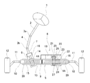
- FIG. 1 is a schematic diagram of an electric power steering device according to a first example of an embodiment of the present invention.
- FIG. 2 is a partially cutaway perspective view showing a steering gear unit and an electric assist device in the electric power steering device of the first example.
- 3A is a plan view of the linear motion shaft of the first example
- FIG. 3B is a view of the linear motion shaft of FIG. 3A as viewed from below.
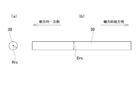
- FIG. 4A is an end view showing a rack shaft portion material for forming a rack shaft portion forming the linear motion shaft of the first example
- FIG. 4B is a side view of FIG. 4A. It is a side view of the material for rack shaft parts seen from the right side.
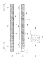
- FIG. 5D are cross-sectional views showing the work of forming the rack tooth portion of the rack shaft portion of the first example in the order of steps.
- FIG. 6A is a plan view of the rack shaft portion of the first example
- FIG. 6B is a view of the rack shaft portion of FIG. 6A as viewed from below.
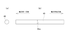
- FIG. 7A is an end view showing a material for a screw shaft portion for forming a screw shaft portion that constitutes the linear motion shaft of the first example
- FIG. 7B is a sectional view of FIG. 7A. It is a side view of the material for screw shaft parts seen from the right side.
- FIG. 8A is a plan view of a screw shaft portion intermediate material for forming the screw shaft portion of the first example
- FIG. 8B is a plan view of the screw shaft portion of the first example.
- FIG. 8C is an enlarged view of part A of FIG.
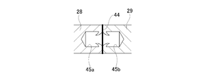
- FIG. 9 is a cross-sectional view of a connecting portion (friction pressure welding portion) between the rack shaft portion and the screw shaft portion of the first example.
- FIG. 10( a) is a plan view of a first screw shaft portion intermediate material for forming a screw shaft portion that constitutes the linear motion shaft of the third example of the embodiment of the present invention
- FIG. [Fig. 10] is a plan view of a second screw shaft portion intermediate material for forming the screw shaft portion of the third example
- Fig. 10(c) is a partially cutaway plan view of the screw shaft portion of the third example.
- FIG. 10( a) is a plan view of a first screw shaft portion intermediate material for forming a screw shaft portion that constitutes the linear motion shaft of the third example of the embodiment of the present invention
- FIG. [Fig. 10] is a plan view of a second
- FIG. 11( a) is a plan view of a first screw shaft portion intermediate material for forming a screw shaft portion that constitutes the linear motion shaft of the fourth example of the embodiment of the present invention
- FIG. 11 is a plan view of a second screw shaft portion intermediate material for forming the screw shaft portion of the fourth example
- FIG. 11C is a plan view of the screw shaft portion of the fourth example.
- FIG. 12(a) is a plan view of a screw shaft portion constituting a linear motion shaft of a fifth example of the embodiment of the present invention
- FIG. 12(b) is a screw shaft shown in FIG. 12(a). It is an enlarged view of the left end part of the part.
- FIG. 12(a) is a plan view of a first screw shaft portion intermediate material for forming a screw shaft portion that constitutes the linear motion shaft of the fourth example of the embodiment of the present invention
- FIG. 11 is a plan view of a second screw shaft portion intermediate material for forming the screw shaft portion of the fourth example
- FIG. 13 is a top view of the screw shaft part which comprises the linear-motion axis
- FIG. 14 is a side view of the rack shaft part which comprises the linear-motion shaft of the 8th example of embodiment of this invention.
- FIG. 15 is a side view of the rack shaft part which comprises the linear-motion shaft of the 9th example of embodiment of this invention.
- FIG. 16 is a schematic diagram of a steering device of a tenth example of the embodiment of the present invention.
- the front-rear direction means the front-rear direction of the vehicle.
- the steering device of this example has a function of pushing and pulling a tie rod to give a steering angle to the left and right steered wheels 12 according to an operation amount of the steering wheel 1 by the driver, and the driver operates the steering wheel 1. It consists of an electric power steering ring device that has both the function of reducing the force required for it.
- the steering device of this example is characterized by the configuration of the linear drive shaft 9.
- the direct acting shaft 9 of this example includes a screw shaft portion 29 having a ball screw portion 16 on an outer peripheral portion, a rack shaft portion 28 having a rack tooth portion 15 on an outer peripheral portion, a rack shaft portion 28 and a screw shaft portion 29. And a frictional pressure welding portion 44 which is a coupling portion.
- the ball screw portion 16 corresponds to the first input portion
- the screw shaft portion 29 corresponds to the first shaft portion
- the rack shaft portion 28 corresponds to the second shaft portion.
- the electric motor 19 causes the ball screw portion 16 to move the linear motion shaft 9 linearly in the axial direction.
- Driving force is applied. Specifically, the rotation of the output shaft 21 of the electric motor 19 is transmitted to the ball nut 23 via the drive pulley 25, the endless belt 26, and the driven pulley 27.
- the rotation of the ball nut 23 is converted into a linear motion in the axial direction by the ball screw mechanism 20 including the ball nut 23 and the ball screw portion 16 in the axial direction. This reduces the force required for the driver to operate the steering wheel 1.
- the steering device includes a steering wheel 1, a steering shaft 2, a pair of universal joints 3 a and 3 b, an intermediate shaft 4, a rack and pinion type steering gear unit 5, and an electric assist device 6.
- a steering wheel 1 a steering shaft 2
- a pair of universal joints 3 a and 3 b an intermediate shaft 4
- a rack and pinion type steering gear unit 5 a rack and pinion type steering gear unit 5.
- the steering wheel 1 is supported and fixed to the rear end of the steering shaft 2 which is rotatably supported with respect to the vehicle body.
- the front end of the steering shaft 2 is connected to the input shaft 7 of the steering gear unit 5 via the rear universal joint 3a, the intermediate shaft 4, and the front universal joint 3b.
- the input shaft 7 can be rotated by rotating the steering wheel 1.
- the rotational movement of the input shaft 7 is converted into the linear movement of the linear movement shaft 9 of the steering gear unit 5.
- the pair of tie rods 11 connected to the axial ends of the linear drive shaft 9 via the ball joints 10 are pushed and pulled, and the steering angles corresponding to the operation amount of the steering wheel 1 are applied to the left and right steered wheels 12. Granted.
- the electric assist device 6 applies a steering assisting force to the linear motion shaft 9 for the linear motion shaft 9 to make a linear motion. This reduces the force required for the driver to operate the steering wheel 1.
- a rack-and-pinion type steering gear unit 5 that constitutes a steering device includes a housing 13 fixed to a vehicle body, an input shaft 7, a torsion bar (not shown), a pinion shaft 8, a direct drive shaft 9, and a pressing force (not shown). And a mechanism.
- the pinion shaft 8 has a pinion tooth portion 14 at its tip.
- the pinion shaft 8 is arranged at the tip of the input shaft 7 coaxially with the input shaft 7, and is connected to the input shaft 7 via a torsion bar so that torque can be transmitted.
- the pinion shaft 8 is rotatably supported inside the housing 13 by a rolling bearing (not shown).
- the linear drive shaft 9 is arranged on one axial side portion (left side portion of FIGS. 1 to 3B) and has a rack shaft portion 28 having a rack tooth portion 15 on the outer peripheral portion and the other axial side portion (FIGS. 1 to 3 (the right side portion of FIG. 3B), and a screw shaft portion 29 having a ball screw portion 16 on the outer peripheral portion, and a friction pressure welding portion 44 that is a joint portion between the rack shaft portion 28 and the screw shaft portion 29. Equipped with. That is, in the linear motion shaft 9, the end of the rack shaft portion 28 on the other side in the axial direction and the end of the screw shaft portion 29 on the one side in the axial direction, which are separately manufactured, are coupled by friction welding. Is formed by.
- the ball screw portion 16 has a male screw groove 55 formed in a spiral shape in a range from the axially intermediate portion of the linear motion shaft 9 to the end portion on the other axial side thereof and having a substantially semicircular cross-sectional shape.
- Both the rack tooth portion 15 and the ball screw portion 16 are formed by plastic working. Specifically, the rack tooth portion 15 is formed by forging. The ball screw portion 16 is formed by rolling.
- the rack shaft portion 28 and the screw shaft portion 29 are both configured by solid shaft portions.
- one or both of the rack shaft portion 28 and the screw shaft portion 29 may be configured by a hollow shaft portion.
- the linear motion shaft 9 is moved linearly in the axial direction with respect to the housing 13 by the ball screw portion 16 constituting the ball screw mechanism 20 being screwed into the plurality of balls 24 constituting the ball screw mechanism 20. Supported as possible.
- the rack tooth portion 15 of the linear drive shaft 9 meshes with the pinion tooth portion 14 of the pinion shaft 8. As a result, the rotational movement of the pinion shaft 8 is converted into the linear movement of the linear movement shaft 9.
- the rotation of the linear motion shaft 9 with respect to the housing 13 is prevented by the engagement between the rack tooth portion 15 and the pinion tooth portion 14.
- the specific stroke (the axial movement amount of the direct drive shaft 9/the rotation angle of the pinion shaft 8) corresponding to the axial movement amount of the direct drive shaft 9 per rotation angle of the pinion shaft 8 is , VGR (variable gear ratio) structure that changes according to the rotation angle of the pinion shaft 8.
- the specific stroke is set to a constant low value in the vicinity of the center portion of the stroke, that is, in the vicinity of the neutral rotation position which is the rotation position of the steering wheel 1 when the vehicle is traveling straight.
- the specific stroke is set to a constant high value in the vicinity of both ends of the stroke, that is, in the vicinity of the rotational position of the steering wheel 1 when the steering wheel 1 is steered to the steering limit (so-called end contact state).
- the specific stroke changes continuously or stepwise near the center of the stroke and near both ends of the stroke. For this reason, the specifications of the tooth pitch of the rack tooth portion 15, the tooth shape, the inclination angle of the tooth trace, and the like are changed according to the axial position.
- the steering gear unit 5 since the steering gear unit 5 has the VGR structure, the turning angle of the steered wheels 12 with respect to the operation amount of the steering wheel 1 becomes small in the vicinity of the center portion of the stroke, so that the traveling stability during straight traveling is improved. The nature is enhanced.
- the pressing mechanism is housed inside the housing 13 on the opposite side in the radial direction of the pinion shaft 8 with the linear motion shaft 9 interposed therebetween, and the linear motion shaft 9 is directed toward the pinion shaft 8 based on the elasticity of the spring. Energize. As a result, the meshing state between the pinion tooth portion 14 and the rack tooth portion 15 is appropriately maintained, the generation of abnormal noise at the meshing portion between the pinion tooth portion 14 and the rack tooth portion 15 is suppressed, and the steering wheel 1 The feeling of operation is improved.
- the steering device of this example includes an electric assist device 6.
- the electric assist device 6 is arranged inside the housing 13, and includes a torque sensor 18, an electric motor 19, a ball screw mechanism 20, and a controller (not shown).
- the auxiliary power of the electric motor 19 that constitutes the power steering device of this example is applied to the linear drive shaft 9 to reduce the force required for the driver to operate the steering wheel 1. Is possible.
- the steering wheel 1 is rotated, the direction and magnitude of the torque transmitted from the steering wheel 1 to the input shaft 7 are detected by the torque sensor 18 and transmitted to a control unit (not shown).
- the control unit controls the amount of electricity supplied to the electric motor 19 according to the direction and magnitude of the torque detected by the torque sensor 18, the vehicle speed, and the like, and rotationally drives the output shaft 21 of the electric motor 19.
- the rotation of the output shaft 21 is transmitted to the ball nut 23 constituting the electric power steering device of this embodiment via the drive pulley 25, the endless belt 26, and the driven pulley 27.
- the ball screw mechanism 20 converts the rotational movement of the ball nut 23 into an axial linear movement of the linear shaft 9.
- the ball screw mechanism 20 is freely rotatable between a spiral female screw groove 22 provided on the inner peripheral surface of the ball nut 23, a male screw groove 55 of the ball screw portion 16, and the female screw groove 22 and the male screw groove 55. And a plurality of balls 24 arranged in The ball nut 23 is screwed into the ball screw portion 16 via a plurality of balls 24.
- the ball nut 23 is rotatably supported by the rolling bearing 54 (see FIG. 2) or the like with respect to the housing 13.
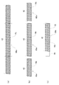
- the ball screw portion 16 has a complete rolling portion 42 at an axially intermediate portion as shown in FIGS. Has an incompletely rolled portion 43.
- the completely rolled portion 42 is a portion having stable lead groove shape accuracy and the like and having a predetermined thread height.
- the incompletely rolled portion 43 is a portion where the lead groove shape accuracy is not stable and the thread height is insufficient as compared with the completely rolled portion 42.
- only the completely rolled portion 42 of the ball screw portion 16 is used as an engaging portion with the plurality of balls 24. That is, in this example, the plurality of balls 24 are engaged only with the completely rolled portion 42, and the plurality of balls 24 are not engaged with the partially rolled portion 43, in the axial direction of the ball screw mechanism 20.
- the operating range of is restricted.
- the electric assist device 6 controls the amount of electricity supplied to the electric motor 19 according to the direction and magnitude of the torque detected by the torque sensor 18 and the vehicle speed signal by the control unit while controlling the output shaft 21 of the electric motor 19.
- the rotational movement of the output shaft 21 is transmitted to the ball nut 23 via the drive pulley 25, the endless belt 26, and the driven pulley 27, and the rotational movement of the ball nut 23 is transmitted via the plurality of balls 24. It is converted into an axial linear motion of the linear shaft 9.
- the linear shaft 9 is linearly moved with a force larger than the operating force of the steering wheel 1 by the driver.
- the force required for the driver to operate the steering wheel 1 is reduced.
- the method for manufacturing the steering device of this example includes a step of manufacturing the linear drive shaft 9, which is a component of the steering device of this example.
- the method of manufacturing the steering device of this example is characterized by the method of manufacturing the linear motion shaft 9.
- the method of manufacturing the linear motion shaft 9 of the present example includes a step of manufacturing the rack shaft portion 28 shown in FIGS. 6(a) and 6(b), and a screw shaft shown in FIGS. 8(b) and 8(c).
- the method includes a step of manufacturing the portion 29 and a step of coupling the rack shaft portion 28 and the screw shaft portion 29 by friction welding.
- a rack shaft material 30 as shown in FIGS. 4A and 4B is prepared.
- the material 30 for the rack shaft portion is made of metal and is a solid round bar having a cylindrical shape.
- the metal that is the material of the rack shaft material 30 for example, various steels such as carbon steel for machine structure such as S48C and S53C and alloy steel can be adopted.
- the rack shaft portion 28 is manufactured by forming the rack tooth portion 15 by a cold forging process which is a plastic working process on a part of the outer circumferential portion of the axially intermediate portion of the rack shaft material 30.
- the rack shaft material 30 is set in a groove 32 having an arc-shaped cross section formed on the upper surface of the receiving mold 31.
- the rack shaft portion material 30 is recessed by the front end surface of the pressing punch 33 that extends along the formation direction of the recessed groove portion 32 (the front and back direction in FIG. 5B). Upsetting is performed by strongly pressing in the direction of pressing on the bottom surface of the groove 32. In this upsetting, the portion of the rack shaft material 30 in which the rack teeth 15 are to be formed is crushed in the axial middle portion, and the width dimension is expanded to obtain the rack shaft intermediate material 34.
- the rack shaft intermediate material 34 is set on the bottom 37 of the U-shaped holding hole 36 provided in the die 35.
- the rack shaft intermediate material 34 is strongly pushed toward the bottom 37 by the tooth forming punch 38 inserted into the holding hole 36.
- the processed surface which is the tip end surface of the tooth-forming punch 38, has a shape corresponding to the rack tooth portion 15 to be obtained, that is, a shape in which irregularities are inverted with respect to the shape of the rack tooth portion 15 to be obtained.
- At least the rack tooth portion 15 of the rack shaft portion 28 is subjected to appropriate heat treatment such as high frequency heating to improve mechanical properties such as hardness of the rack tooth portion 15.
- the ends of the rack shaft material 30 are left unprocessed at the ends of the rack shaft 28 on both sides in the axial direction. That is, the rack shaft portion 28 is provided with small-diameter shaft portions 39a and 39b having cylindrical outer peripheral surfaces having the same outer diameter dimension Drs as the rack shaft material 30 at both ends in the axial direction.
- a screw shaft material 40 as shown in FIGS. 7(a) and 7(b) is prepared.
- the screw shaft material 40 is made of metal and is a solid round bar having a cylindrical shape.
- the metal which is the material of the screw shaft material 40 various steels such as carbon steel for machine structure such as S48C and S53C and alloy steel can be adopted.
- the material of the screw shaft material 40 can be the same as or different from the material of the rack shaft material 30 of the rack shaft 28.
- the outer diameter dimension Dbs of the screw shaft material 40 and the outer diameter dimension Drs of the rack shaft material 30 may be different (Dbs ⁇ Drs).
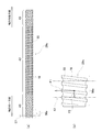
- the outer peripheral portion of the screw shaft material 40 which is the material for the first shaft member, is formed by cold rolling, which is plastic working.
- the ball screw portion 16 that is the first input portion is formed.
- a through-feed rolling process is adopted as the cold rolling process.
- the screw shaft portion intermediate material 17 in which the ball screw portion 16 is formed over the entire axial length of the outer peripheral portion is obtained.
- the screw shaft material 40 is supplied between the pair of rolling dies with the other axial side of the screw shaft material 40 being the leading side. Between the pair of rolling dies, the screw shaft portion material 40 is caused to move in the axial direction by walking. Therefore, when the through-feed rolling process is performed, the ball screw portion 16 is gradually formed on the outer peripheral portion of the screw shaft material 40 from the other side in the axial direction toward the one side in the axial direction.
- the one side in the axial direction of the material 40 for a screw shaft portion may be set as the leading side and supplied between a pair of rolling dies.
- the pair of rolling dies are moved in the radial direction while the screw shaft material 40 is passing axially between the pair of rolling dies. Escape in the direction away from each other. That is, the through-feed rolling process is completed at the time when the pair of rolling dies are released in the radial direction away from each other.
- the axial range corresponding to the end portion on the other side in the axial direction that is first supplied between the pair of rolling dies and the axial range corresponding to the end of the pair of rolling dies comes into contact with the pair of rolling dies at the final stage.
- the axial range corresponding to the end on the one side in the axial direction becomes the rolling incomplete portion 43, and the remaining axial range corresponding to the axially intermediate portion of the ball screw portion 16 is completed. 42 in total.
- the predetermined length dimension is the length dimension of the entire screw shaft portion intermediate material 17. That is, in this example, the predetermined axial range including the axial end portion of the outer peripheral portion of the screw shaft portion 29 where the ball screw portion 16 is formed and which is coupled to the rack shaft portion 28 is the screw shaft portion. It is the entire axial direction of the portion 29.
- the cycle time is reduced and the pair of rolling dies is rolled.
- the life of the die can be improved.
- At least the complete rolling portion 42 is subjected to appropriate heat treatment such as high frequency heating to improve mechanical properties such as hardness of the complete rolling portion 42. ..
- the axial direction of the incompletely rolled portion 43 located on one axial side of the screw shaft intermediate material 17 is used as a reference.
- the outer peripheral portion of the one end is subjected to a cutting process such as a turning process, a grinding process, or a polishing process.
- a centering grip portion 56 which is a cylindrical surface coaxial with the male thread groove 55 of the completely rolled portion 42, is formed on the outer peripheral portion of the axially one end of the screw shaft intermediate material 17.
- the small diameter shaft portion 41 having the outer peripheral portion as the grip portion 56 is formed at the end portion on one axial side of the screw shaft portion intermediate material 17.
- the screw shaft portion 29 as shown in FIG. 8B is obtained.
- the grip portion 56 since the grip portion 56 is formed with the male screw groove 55 as a reference, the shaft of the grip portion 56 does not deviate from the shaft of the ball screw portion 16, and the grip portion 56 has the ball screw. It is coaxial with the section 16.
- the grip portion 56 can be formed by a complete cylindrical surface as shown, or can be formed by a cylindrical surface where the groove bottom of the ball screw portion 16 remains. In this example, only the end of the threaded shaft portion intermediate material 17 on one axial side of the rolling incomplete portion 43 on one axial side is cut to form the grip portion 56. It is also possible to cut the entire range in the direction and use it as the grip portion 56.
- the through-feed rolling process is finished before the screw shaft material 40 has completely passed between the pair of rolling dies, it is possible to quickly By ending the rolling process, the end of the screw shaft portion material 40 on the one axial side can be used as the non-rolled portion, and the outer peripheral portion of the non-rolled portion can be used as it is as the gripping portion.
- the ball screw portion 16 can be formed by shaving.
- the outer diameter dimension in the axial range in which the ball screw portion 16 is formed (the outer diameter dimension Dbg of the complete rolling portion 42) is due to plastic deformation accompanying the rolling process. It is larger than the outer diameter dimension Dbs of the screw shaft material 40 (Dbg>Dbs).
- the outer diameter dimension of the small-diameter shaft portion 41 is about the same as the outer diameter dimension Dbs of the screw shaft material 40 (that is, the same as Dbs, or slightly smaller or slightly larger than Dbs). In other words, it is equivalent to Dbs.
- Friction welding is a method of joining two metal members by abutting the two metal members against each other and rotating them while applying pressure so that frictional heat generated at the abutting portions is used.
- the rack shaft portion 28 and the screw shaft portion 29 are coupled by friction welding, first, the rack shaft portion 28 and the screw shaft portion 29 are centered so that the rack shaft portion 28 and the screw shaft portion 29 are aligned. Are arranged coaxially, and the end surface of the other end portion in the axial direction of the rack shaft portion 28 and the end surface of the small-diameter shaft portion 41, which is one end portion in the axial direction of the screw shaft portion 29, are butted against each other and pressed. In this state, the rack shaft portion 28 and the screw shaft portion 29 are relatively rotated to generate frictional heat at the abutting portion. As a result, the relative rotation is stopped after the butted portion is brought into a high temperature and high pressure state. As a result, the linear motion shaft 9 which becomes the frictional pressure contact portion 44 as the butted portion is cooled is obtained.
- the gripping portion 56 of the screw shaft portion 29 is gripped by the first gripping tool 57 (see FIGS. 3A and 8B) for centering, Moreover, the outer peripheral surface of the small diameter shaft portion 39b of the rack shaft portion 28 is gripped by the second gripping tool 58 (see FIGS. 3A and 6A) for centering the rack shaft portion 28 and the screw. Centering with the shaft portion 29 is performed.
- Friction welding is performed by abutting the ends on the closer side in the axial direction, that is, the end on the other side in the axial direction of the rack shaft portion 28 and the end on the one side in the axial direction of the screw shaft portion 29.
- first gripper 57 and the second gripper 58 various grippers such as a collet chuck and a hydraulic three-jaw chuck can be adopted.
- rack shaft portion 28 the axial portion where the rack tooth portion 15 is located can also be used as a centering grip portion for gripping by the second grip tool 58.
- screw shaft portion 29 the axial portion where the completely rolled portion 42 is located can also be used as a centering gripping portion for gripping by the first gripping tool 57.
- a sleeve 59 is provided around the axially other side portion of the screw shaft portion 29, as indicated by a chain double-dashed line in FIG. Can be placed.
- the screw shaft portion 29 is rotated in a state where the sleeve 59 is fitted onto the other side portion of the screw shaft portion 29 in the axial direction without rattling in the radial direction, and the axial direction of the rack shaft portion 28 is increased.
- Friction welding can be performed by abutting the end on the other side and the end on the one side in the axial direction of the screw shaft portion 29.
- the sleeve 59 is preferably arranged around a portion of the screw shaft portion 29 on the axially opposite side to the side coupled to the rack shaft portion 28, and includes an axial range including a part of the completely rolled portion 42. It is more preferable to arrange it around.
- the axial length of the sleeve 59 is preferably 1 ⁇ 3 or less of the axial length of the screw shaft portion 29. Even if the axial length of the sleeve 59 is made longer than 1/3 of the axial length of the screw shaft portion 29, no further effect can be expected, and the work of fitting the sleeve 59 onto the screw shaft portion 29 is performed. Is troublesome.
- the lower limit of the axial length of the sleeve 59 is not particularly limited, but it is preferably as long as possible from the viewpoint of preventing whirling of the screw shaft portion 29. In short, the axial length of the sleeve 59 is most preferably 1/3 of the axial length of the screw shaft portion 29.
- the rack shaft portion 28 having the rack tooth portion 15 and the screw shaft portion 29 having the ball screw portion 16 are manufactured as separate shaft portions, and then the rack shaft portion is manufactured.
- the axial ends of the portion 28 and the screw shaft portion 29 are joined by friction welding to obtain the linear motion shaft 9. Therefore, in the manufacturing process of the rack shaft portion 28, if a problem occurs in the processing of the rack tooth portion 15, it is sufficient to discard only the rack shaft portion 28, and in the manufacturing process of the screw shaft portion 29, the ball screw portion. If a problem occurs in the processing of 16, only the screw shaft portion 29 may be discarded. That is, it is possible to avoid the inconvenience of having to discard the entire linear motion shaft 9 when a defect occurs only in the processing of one of the rack tooth portion 15 and the ball screw portion 16.
- the rack tooth portion 15 is formed by cold forging. Therefore, compared with the case where the rack tooth portion 15 is formed by a cutting process such as a cutting process, the yield of the material can be improved and the processing time can be shortened.
- the rack tooth portion 15 has a structure (VGR structure) in which the specifications such as the tooth pitch, the tooth shape, and the inclination angle of the tooth trace are changed according to the axial position. , It is difficult to accurately form the rack tooth portion 15 having the VGR structure in a short time by the shaving process.
- the rack tooth portion 15 is formed by cold forging, by making the processing surface of the tooth forming punch 38 (FIG. 5) into a shape corresponding to the rack tooth portion 15 to be obtained, It is easy to accurately form the rack tooth portion 15 in a short time.
- the ball screw portion 16 is formed by cold rolling, which is plastic working. Therefore, compared with the case where the ball screw portion 16 is formed by a cutting process such as a cutting process, the yield of the material can be improved and the processing time can be shortened.
- the through-feed rolling process is adopted as the cold rolling process, the complete rolling part 42 of the ball screw part 16 is short-timed in a wide axial range of the axially intermediate part of the screw shaft part 29. Can be formed with. Then, the completely rolled portion 42 of the ball screw portion 16 can be provided in a wide axial range of the end portion on the other axial side of the linear motion shaft 9 after completion.
- the engageable range of the ball 24 of the ball screw mechanism 20 with respect to the direct acting shaft 9 can be widened in the axial direction.
- the flexibility of the product design layout, more specifically, the degree of freedom of the installation position of the ball nut 23 or the like with respect to the housing 13 in the axial direction can be increased.
- incomplete rolling portions 43 are formed at both ends of the ball screw portion 16 in the axial direction.
- the incompletely rolled portion 43 is less stable in lead groove shape accuracy than the completely rolled portion 42 and lacks in thread height, so that it is used as a rolling portion of the ball 24 constituting the ball screw mechanism 20.
- the outer peripheral portion of at least the end portion on one side in the axial direction of the rolling incomplete portion 43 on one side in the axial direction forming the screw shaft portion intermediate material 17 is shaved to form the small-diameter shaft portion 41.
- the outer peripheral portion of the small-diameter shaft portion 41 is effectively used as a grip portion 56 for centering when friction welding is performed. Therefore, according to this example, the screw shaft portion 29 can be manufactured in a short time while sufficiently suppressing the waste of material.
- friction welding is used as a method of connecting the axial ends of the rack shaft portion 28 and the screw shaft portion 29. Friction welding can shorten the time required for joining, so that the manufacturing efficiency of the linear motion shaft 9 can be improved, and the bondability between dissimilar materials can be enhanced, so that the rack shaft portion 28 and the screw shaft portion 29 can be connected. Even when different materials are used, the bondability between the rack shaft portion 28 and the screw shaft portion 29 can be increased.
- the grip portion 56 of the screw shaft portion 29 gripped by the first gripper 57 has one axial direction on the side of the screw shaft portion 29 that is coupled to the rack shaft portion 28.
- the outer peripheral surface of the small-diameter shaft portion 39b of the rack shaft portion 28, which is located at the end on the side and is gripped by the second gripper 58, is on the side of the rack shaft portion 28 that is coupled to the screw shaft portion 29. It is located at the other end in the axial direction. Therefore, when performing frictional pressure welding, it is possible to sufficiently suppress whirling in the radial direction between the ends of the rack shaft portion 28 and the screw shaft portion 29 on the side closer to each other.
- the gripping portion 56 of the screw shaft portion 29 gripped by the first gripping tool 57 is formed by the ball screw portion 16 after the ball screw portion 16 is formed and the heat treatment is performed, and the ball screw portion 16 is subjected to a cutting process based on the male screw groove 55. It is formed coaxially with the portion 16. Therefore, of the screw shaft portion 29, the coaxiality between the ball screw portion 16 and the gripping portion 56 gripped by the first gripping tool 57 can be favorably ensured. Therefore, as in the method described in Japanese Patent Application Laid-Open No. 2005-247163, compared with the case where friction processing is performed by chucking an unprocessed supporting portion of the shaft material that does not form a thread groove, The centering accuracy of the screw portion 16 can be increased. As a result, according to the present example, it is possible to secure good coaxiality between the portion having the rack tooth portion 15 and the portion having the ball screw portion 16 with respect to the linear drive shaft 9. In other words, the straightness of the linear drive shaft 9 can be improved.
- the rack tooth portion 15 is formed by performing cold forging on the axial intermediate portion of the rack shaft material 30 and at the same time, the unprocessed shaft of the rack shaft material 30 is formed.
- the ends on both sides in the direction are small-diameter shaft portions 39a and 39b.
- the rack shaft portion material 30 is Alternatively, the rack shaft portion material 30 or the rack shaft portion intermediate material 34 is processed in a state where a part of the outer peripheral surface of the rack shaft portion intermediate material 34 in the circumferential direction is constrained by the receiving mold 31 or the die 35.
- the rack shaft portion 28 after the formation of the rack tooth portion 15 is left as it is.
- the screw shaft portion 29 may be joined by friction welding.
- the direct acting shaft 9 of this example has an end portion on the other axial side of the small diameter shaft portion 39b having the same outer diameter dimension as the outer diameter dimension of the rack shaft material 30, and the outer diameter dimension of the screw shaft material 40. And an end portion on one axial side of the small-diameter shaft portion 41 having an outer diameter dimension similar to that of the small-diameter shaft portion 41 by friction welding. Therefore, for example, the area of the frictionally welded portion can be reduced as compared with the case of frictionally pressure-welding the portions to be fitted with each other, and the equipment pressure can be reduced by reducing the pressure applied when performing the frictional pressure welding. It is possible to achieve cost reduction by reducing cost and shortening cycle time.
- the plastic working (forging, rolling, etc.) for forming the rack tooth portion and the ball screw portion is not limited to cold, but warm or hot. You can also do it in. Even when the plastic working is performed warm or hot, the yield of the material is improved or the processing time is shortened as compared with the case where the rack tooth portion and the ball screw portion are formed by shaving. It is possible to obtain advantageous effects such as
- FIGS. 8(a) to 8(c) A second example of the embodiment of the present invention will be described with reference to FIGS. 8(a) to 8(c).
- the specific method of the through-feed rolling process for forming the ball screw portion 16 is different from that of the first example.
- the through-feed rolling process ends when the entire screw shaft material 40 has completely passed in the axial direction between the pair of rolling dies. Therefore, in this example, the axial range corresponding to the end on the other side in the axial direction first supplied between the pair of rolling dies of the ball screw portion 16 and the pair of rolling dies.
- the axial range corresponding to the end on the one axial side that last passed between the two becomes the incompletely rolled portion 43 of the ball screw portion 16, and corresponds to the axial intermediate portion of the ball screw portion 16.
- the remaining axial range is the complete rolling portion 42.
- the axial length of the incompletely rolled portion 43 on the one axial side is made sufficiently shorter than that in the first example. can do.
- the axial length of the completely rolled portion 42 of the ball screw portion 16 included in the screw shaft portion 29 can be made longer than that in the first example. Therefore, the engageable range of the ball 24 of the ball screw mechanism 20 with respect to the direct acting shaft 9 can be made wider in the axial direction.
- the axial length of the incompletely rolled portion 43 on one axial side is less than the axial length required for the gripping portion 56 to be gripped by the first gripper 57, one axial Not only the incompletely rolled portion 43 on the side but also a part of the completely rolled portion 42 adjacent to the incompletely rolled portion 43 is shaved to secure an axial length required for the grip portion 56. do it.
- Other configurations and operations are similar to those of the first example.
- FIGS. 10(a) to 10(c) A third example of the embodiment of the present invention will be described with reference to FIGS. 10(a) to 10(c).
- the outer circumference of the screw shaft portion material having a columnar shape and having an axial dimension twice as large as the axial dimension of the screw shaft portion 29a to be obtained.
- the portion is subjected to through feed rolling processing to form the ball screw portion 16z.
- the first screw shaft portion intermediate material 64 having the ball screw portion 16z over the entire axial length of the outer peripheral portion is obtained.
- the ball screw portion 16z has a completely rolled portion 42z at an intermediate portion in the axial direction, and has incompletely rolled portions 43 at both end portions in the axial direction.
- the first screw shaft portion intermediate material 64 is cut at the axial center position, and the second screw shaft portion intermediate material 65 having the ball screw portion 16a on the outer peripheral portion as shown in FIG. Get one.
- Each of the ball screw portions 16a of the second screw shaft portion intermediate material 65 is on one side in each axial direction (the left side of the second screw shaft portion intermediate material 65 on the left side of FIG. 10(b), the right side of FIG. 10(b)).
- the outer peripheral portion of the incompletely rolled portion 43 is shaved to form the completely threaded portion constituting the completely rolled portion 42.
- a gripping portion 56 for centering which is a cylindrical surface coaxial with 55, is formed.
- the small-diameter shaft portion 41 having the outer peripheral portion as the grip portion 56 coaxial with the ball screw portion 16a is formed at the end portion on the one axial side of the second screw shaft portion intermediate material 65.
- the end portion on one side in the axial direction where the incompletely rolled portion 43 (small diameter shaft portion 41) is provided is on the other side in the axial direction (see FIG.
- a bottomed screw hole 66 is formed on the right side of the second screw shaft portion intermediate material 65 on the left side, and on the right side of the second screw shaft portion intermediate material 65 on the right side of FIG.
- the screw shaft portion 29a as shown in FIG. 10(c) is obtained.
- a male screw portion provided on the base end portion of the tie rod 11 is screwed into the screw hole 66.
- the screw shaft portion 29a is joined to the rack shaft portion 28 (see FIGS. 6A and 6B) by friction welding to obtain the linear motion shaft 9 (FIGS. 1 to 3B).
- the grip portion 56 of the screw shaft portion 29a is gripped by the first gripping tool 57 for centering.
- the complete rolling portion 42 is formed from the intermediate portion in the axial direction to the end portion on the other side in the axial direction.
- the screw shaft portion 29a of the present example it is easier to secure a longer axial length of the completely rolled portion 42 than the screw shaft portion 29 of the first example. That is, according to this example, it is easier to secure the engageable range of the ball 24 of the ball screw mechanism 20 with respect to the linear motion shaft 9 in the axial direction longer than in the first example.
- Other configurations and operations are similar to those of the first example.
- FIGS. 11(a) to 11(c) A fourth example of the embodiment of the present invention will be described with reference to FIGS. 11(a) to 11(c).
- a predetermined axial dimension exceeding the axial dimension of the screw shaft portion 29b to be obtained specifically, several times the axial dimension of the screw shaft portion 29b to be obtained.
- the ball screw portion 16z is formed by subjecting the outer peripheral portion of the long-sized screw shaft portion material having the axial dimension of preferably three times or more and the columnar shape to the through-feed rolling process. To do.
- a long first screw shaft portion intermediate material 64a having the ball screw portion 16z on the outer peripheral portion is obtained.
- the upper limit of the predetermined axial dimension relating to the material for the screw shaft portion is arbitrary, and is determined according to the length of the available long material for the screw shaft portion.
- first screw shaft portion intermediate material 64a is cut into the axial dimension of the screw shaft portion 29 to be obtained, and the entire length in the axial direction is provided on the outer peripheral portion as shown in FIG. 11(b).
- a second screw shaft portion intermediate material 65a having a ball screw portion 16b is obtained.
- a plurality of, preferably three or more, second screw shaft portion intermediate materials 65a are obtained from one first screw shaft portion intermediate material 64a.
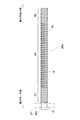
- the ball screw portion 16b of the second screw shaft portion intermediate material 65a includes only the completely rolled portion 42. That is, according to the present example, the ball screw portion 16b can be the complete rolling portion 42 over the entire length.
- a gripping portion 56 for centering is formed on the end portion on the one axial side of each of the second screw shaft portion intermediate materials 65a by cutting.
- the second screw shaft portion intermediate material 65a has the complete rolling portion 42 on the outer peripheral portion over the entire length. Therefore, the grip portion 56 is formed by cutting the end portion of the second screw shaft portion intermediate material 65a on one side in the axial direction by the minimum required length for gripping by the first grip tool 57. As a result, the screw shaft portion 29b as shown in FIG. 11(c) is obtained.
- the long screw shaft material is subjected to through-feed rolling to obtain a long first screw shaft intermediate material 64a, and then the first screw shaft intermediate material 64a is In the second thread shaft portion intermediate material 65a obtained by cutting, the shape accuracy of the male thread groove 55 in the complete rolling portion 42 is good, but the shape accuracy of the outer peripheral surface of the thread is good. Not necessarily.
- the ball screw is used as a reference.
- the grip portion 56 is formed by subjecting the end portion of the portion 16b on the one side in the axial direction where the grip portion 56 is to be formed to a cutting process.
- the screw shaft portion 29b is joined to the rack shaft portion 28 (see FIGS. 6(a) and 6(b)) by friction welding to obtain the linear motion shaft 9 (FIGS. 1 to 3(b)).
- the gripping portion 56 of the screw shaft portion 29 is gripped by the first gripping tool 57 for centering.
- the screw shaft portion 29b is obtained by forming the grip portion 56 by shaving the portion. Therefore, according to the screw shaft portion 29b of the present example, it is easier to secure a longer axial length of the completely rolled portion 42 than the screw shaft portion 29a of the third example. That is, according to this example, it is easier to secure a longer engageable range of the ball 24 of the ball screw mechanism 20 with respect to the direct acting shaft 9 in the axial direction than in the second example.
- the screw shaft portion 29b of the present example has the completely rolled portion 42 up to the end portion on the other axial side, the axial direction including a part of the completely rolled portion 42 of the screw shaft portion 29b during friction welding. It is easy to arrange the sleeve 59 (see FIG. 3A) around the range. Other configurations and operations are similar to those of the first and second examples.
- FIGS. 12(a) and 12(b) A fifth example of the embodiment of the present invention will be described with reference to FIGS. 12(a) and 12(b).
- the amount of radial shaving in the process of forming the grip portion 56a is smaller than that in the first example. That is, in the first example, as shown in FIG. 8B, by removing all the thread ridges existing at one end in the axial direction of the ball screw portion 16 where the grip portion 56 is to be formed, The grip portion 56, which is a surface, is formed.
- FIG. 8B by removing all the thread ridges existing at one end in the axial direction of the ball screw portion 16 where the grip portion 56 is to be formed.
- the ball screw portion 16 only the radially outer portion of the screw thread existing at the end portion on the one axial side where the grip portion 56a is to be formed.
- the grip portion 56a coaxial with the male thread groove 55 of the completely rolled portion 42 is formed on the outer peripheral surface of the thread at the end portion on the one axial side.
- the work for forming the grip portion 56a can be performed in a short time.
- the rotation direction of the screw shaft portion 29c is devised in the process of joining the rack shaft portion 28 (see FIGS. 1 to 3B) and the screw shaft portion 29c by friction welding. That is, in this example, in the step of joining the rack shaft portion 28 and the screw shaft portion 29c by friction welding, when the ball screw portion 16 is viewed from the outside in the radial direction, the ball screw portion 29c rotates and the ball screw portion 29c rotates.
- the screw shaft portion 29c is rotated in a rotation direction in which the thread of the portion 16 appears to move to one side in the axial direction, which is a direction toward the rack shaft portion 28. Specifically, in FIGS.
- the outer diameter difference between the grip portion 56a and the portion other than the grip portion 56a in the screw shaft portion 29c can be reduced by reducing the amount of radial shaving in the step of forming the grip portion 56a. Therefore, it is easy to use a collet chuck with high centering accuracy as the first gripper 57 that grips the grip portion 56a. That is, when a collet chuck is used as the first gripper 57, the portion of the collet chuck other than the grip portion 56a is axially passed through the center hole of the collet chuck, and then the diameter of the collet chuck is reduced to reduce the diameter of the collet chuck. The grip portion 56a is gripped by.
- the amount of collet chuck that can be reduced in diameter at this time is usually limited to a small value of about several mm. Therefore, when the outer diameter difference between the gripping portion 56a and the portion other than the gripping portion 56a of the screw shaft portion 29c is larger than the diameter reduction amount of the collet chuck, the gripping portion 56a is gripped by the collet chuck. It may not be possible. On the other hand, in the screw shaft portion 29a of the present example, since the difference in outer diameter between the grip portion 56a and the portion other than the grip portion 56a is small, the grip portion 56a can be easily gripped by a normal collet chuck.
- the ball screw portion 16 can also be formed by shaving. If the ball screw portion 16 is formed by shaving, the effect that the time required to form the ball screw portion 16 according to this example can be shortened can be more remarkably obtained.
- Other configurations and operations are similar to those of the first example.
- a seventh example of the embodiment of the present invention will be described with reference to FIG.
- the screw shaft material 40 (see FIG. 7) is subjected to the rolling process, so that the shaft of the screw shaft material 40 is formed.
- the ball screw portion 16 is formed only on the portion other than the end portion on one side in the direction, and the end portion on one side in the axial direction of the screw shaft material 40 is left as a non-rolled portion. Then, the outer peripheral portion of the non-rolled portion is shaved with reference to the male thread groove 55 of the completely rolled portion 42 of the ball screw portion 16 to form the grip portion 56b.
- the rolling method for forming the ball screw portion 16 is different from that in the sixth example.
- the ball screw portion 16 shown in FIG. 11 is gradually formed from one side in the axial direction toward the other side in the axial direction. Therefore, first of all, in the screw shaft material 40, an axial intermediate portion deviated from an end portion on one axial side where the grip portion 56b is to be formed, that is, a portion where the ball screw portion 16 is to be formed.
- the rolling processing of the ball screw portion 16 is started by sandwiching the end portion on one side in the axial direction from both sides in the radial direction with a pair of rolling dies.
- the ball screw part 16 is moved from one axial side to the other axial direction by moving the screw shaft material 40 toward the one axial side with respect to the pair of rolling dies. Form gradually toward the side.
- the step movement of the material 40 for the screw shaft portion is performed until the material 40 for the screw shaft portion completely comes out between the pair of rolling dies to one side in the axial direction.
- the ball screw portion 16 is formed by such through-feed rolling processing.
- the through-feed rolling process of this example can also be referred to as an in-feed rolling process in which the work moves in steps.
- the ball screw portion 16 formed by the rolling process has the complete rolling portion 42 at the intermediate portion in the axial direction and a pair of rolling incomplete portions at both axial end portions. Will have all 43.
- Other configurations and operations are similar to those of the first and sixth examples.
- the protruding portion is improved. It is desirable to regulate the axial position of the portion to be gripped by the second gripper 58a so that the axial dimension thereof is as short as possible.
- the rack shaft portion 28b in the step of joining the rack shaft portion 28b and the screw shaft portion 29 by friction welding, the end surface on the other axial side of the rack shaft portion 28b on the stationary side and one axial direction of the screw shaft portion 29 on the rotating side.
- the rack shaft portion 28b is formed after the rack tooth portion 15 is formed and heat-treated in the step of manufacturing the rack shaft portion 28b.
- the orthogonal surface 60 which is a plane orthogonal to the central axis of the portion having the rack tooth portion 15, is formed on the end surface.
- Other configurations and operations are similar to those of the first example.
- the screw shaft portion in the step of joining the rack shaft portion and the screw shaft portion by friction welding, is the rotating side and the rack shaft portion is the non-rotating side.
- the screw shaft portion when the grip portion is formed on the rack shaft portion, the screw shaft portion may be the non-rotating side and the rack shaft portion may be the rotating side.
- the screw shaft portion and the rack shaft portion can be rotated in opposite directions.
- the linear drive shaft 9a constituting the steering device of this example has one rack shaft portion 28 having one rack tooth portion 15 on the outer peripheral portion and the other rack shaft portion 28 having the other rack tooth portion 15a on the outer peripheral portion. It is formed by joining the portion 28c with friction welding.
- One rack tooth portion 15 meshes with the pinion tooth portion 14 of the pinion shaft 8
- the other rack tooth portion 15a meshes with the pinion tooth portion 14a of another pinion shaft 8a.
- the control unit of the electric assist device 6a controls the amount of electricity supplied to the electric motor 19a according to the direction and magnitude of the torque detected by the torque sensor 18 and the vehicle speed signal, while the electric motor 19a passes the speed reducer 61 through the speed reducer 61. And another pinion shaft 8a is rotationally driven. Then, the meshing portion of the other rack tooth portion 15a and the pinion tooth portion 14a converts the rotational movement of the other pinion shaft 8a into the linear movement of the linear drive shaft 9a, so that a steering assist force is applied to the linear drive shaft 9a.
- the other rack tooth portion 15a corresponds to the first input portion
- the other rack shaft portion 28c corresponds to the first shaft portion
- one rack shaft portion 28 functions as the second shaft portion. Equivalent to.
- the method of manufacturing the linear motion shaft 9a of this example includes a step of manufacturing one rack shaft portion 28, a step of manufacturing the other rack shaft portion 28c, one rack shaft portion 28 and the other rack shaft portion 28c. Are joined by friction welding.
- the step of manufacturing the other rack shaft portion 28c further includes the step of forming the grip portion 56c after the same step as the step of manufacturing the one rack shaft portion 28.
- the step of forming the grip portion 56c after the other rack tooth portion 15a is formed and the heat treatment is performed, the outer peripheral portion of the axial end portion of the other rack shaft portion 28c closer to the one rack shaft portion 28. Then, the grip portion 56c for centering is formed by shaving with reference to the other rack tooth portion 15a. Thereby, the grip portion 56c is finished coaxially with the axial portion having the other rack tooth portion 15a.
- the grip portion 56c of the other rack shaft portion 28c is aligned with the first gripping tool 57 for centering (see FIG. 3A). ), and the outer peripheral surface of the small diameter shaft portion 39b of the one rack shaft portion 28 is gripped by the second gripping tool 58 (see FIG. 3A) for centering.
- the first gripper 57 to rotate the other rack shaft portion 28c, while holding the one rack shaft portion 28 non-rotating, one rack shaft portion 28 and the other rack shaft portion 28c are held.
- the one rack shaft portion 28 and the other rack shaft portion 28c are coupled by friction welding.
- one rack shaft portion 28 in the step of joining one rack shaft portion 28 and the other rack shaft portion 28c by friction welding, one rack shaft portion 28 is the non-rotating side and the other rack shaft portion 28c is the rotating side.
- one rack shaft portion 28 includes the grip portion, one rack shaft portion 28 can be the rotation side and the other rack shaft portion 28c can be the non-rotation side.
- one rack shaft portion 28 and the other rack shaft portion 28c can be rotated in mutually opposite directions. Other configurations and operations are similar to those of the first example.
- the first to tenth examples of the embodiment of the present invention can be appropriately combined with each other as long as no contradiction occurs.
- the present invention relates to, for example, a linear shaft that constitutes a steering device of a system that applies a steering assist force to a portion other than a linear shaft or a steering device of a steer-by-wire system, the rack shaft having a rack tooth portion on an outer peripheral portion. It is also possible to apply to a direct acting shaft provided with a portion, an extension shaft portion which is a cylindrical or cylindrical round bar, and a friction welding portion in which a rack shaft portion, an extension shaft portion, and axial end portions are joined together. ..
- One of the extension shafts to be rotated can be the rotating side and the other can be the non-rotating side, or they can be rotated in opposite directions.
- the present invention is, for example, a direct acting shaft that constitutes a steering device of a steer-by-wire system, and a screw shaft portion having a ball screw portion on the outer peripheral portion and an extension shaft portion that is a cylindrical or cylindrical round bar.
- the present invention can be applied to a direct acting shaft including a frictional pressure contact portion that is a connecting portion between a screw shaft portion and an extension shaft portion.
- a frictional pressure contact portion that is a connecting portion between a screw shaft portion and an extension shaft portion.
- Either one may be the rotating side and the other may be the non-rotating side, or they may be rotated in opposite directions.
Landscapes
- Engineering & Computer Science (AREA)
- Mechanical Engineering (AREA)
- General Engineering & Computer Science (AREA)
- Chemical & Material Sciences (AREA)
- Combustion & Propulsion (AREA)
- Transportation (AREA)
- Transmission Devices (AREA)
- Power Steering Mechanism (AREA)
- Pressure Welding/Diffusion-Bonding (AREA)
Abstract
第1軸部と第2軸部とを摩擦圧接により結合した直動軸に関して、第1入力部を有する部分と第2入力部を有する部分との同軸度を向上させる。第1軸部であるねじ軸部29に芯出し用の把持部56を設けて、ねじ軸部29の把持部56を芯出し用の第1把持具57により把持し、かつ、第2軸部であるラック軸部28を芯出し用の第2把持具58により把持した状態で、第1把持具57と第2把持具58とのうちの少なくとも一方の把持具を回転駆動することにより、ねじ軸部29とラック軸部28とを相対回転させながら、ラック軸部28とねじ軸部29の軸方向端部同士を突き合わせることで、ラック軸部28とねじ軸部29とを摩擦圧接により結合する。
Description
本発明は、自動車などの車両用のステアリング装置を構成する直動軸、該直動軸を含むステアリング装置、およびこれらの製造方法に関する。
自動車などの車両用のステアリング装置では、ステアリングホイールの回転は、ステアリングギヤユニットの入力軸に伝達され、該入力軸の回転は、車体の幅方向に配置された直動軸(ラック軸)の軸方向の直線運動に変換される。これにより、直動軸の軸方向両側の端部に支持されたタイロッドが押し引きされて、操舵輪に舵角が付与される。
運転者がステアリングホイールを操作するために要する力を低減するための電動アシスト装置を含む、電動パワーステアリング装置からなる、ステアリング装置が広く実施されている。電動パワーステアリング装置は、電動モータの補助動力を、ステアリングホイールの回転に伴って回転または直線運動する部材に付与する。電動パワーステアリング装置としては、補助動力をステアリングシャフトに付与するコラムアシストタイプと、補助動力をステアリングギヤユニットの入力軸(ピニオン軸)に付与するピニオンアシストタイプと、補助動力をステアリングギヤユニットの直動軸に付与するラックアシストタイプとの3種類が知られている。これらのうち、ラックアシストタイプの電動パワーステアリング装置は、高出力化しやすいといった利点がある。
ラックアシストタイプの電動パワーステアリング装置では、電動モータの回転トルクを、ボールねじ機構により、直動軸の軸方向の直線運動に変換して、該直動軸に付与する。この直動軸は、軸方向一方側部分に、ステアリングホイールの回転に伴い回転する入力軸のピニオン歯部と噛合するラック歯部を備え、かつ、軸方向他方側部分に、略半円弧形の断面形状を有する雌ねじ溝をらせん状に形成されている、ボールねじ部を備える。この直動軸を1つの素材から製造しようとすると、ラック歯部とボールねじ部とのいずれか一方の部位の形状精度や寸法精度が不十分であった場合に、不良品として廃棄しなければならず、コスト低減の面から不利である。
特開2005-247163号公報には、外周部にラック歯を有するラック軸と、外周部にねじ溝を有するねじ軸とを摩擦圧接により結合する、直動軸の製造方法が記載されている。特開2005-247163号公報に記載の方法では、ラック軸を製造する工程において、精度良く仕上げられた軸部用素材の軸方向一部の外周部に加工を施すことによって、ラック歯を形成し、かつ、前記軸部用素材の残部の外周部を支持部として未加工のまま残す。また、ねじ軸を製造する工程において、精度良く仕上げられた軸部用素材の軸方向一部の外周部に加工を施すことによって、ねじ溝を形成し、かつ、前記軸部用素材の残部の外周部を支持部として未加工のまま残す。そして、ラック軸の支持部と、ねじ軸の支持部とをチャックすることにより、ラック軸とねじ軸との芯出しを行った状態で、ラック軸とねじ軸を摩擦圧接により結合する。これにより、直動軸のうちのラック歯を有する部分とねじ溝を有する部分との同軸度が許容範囲内に収まるようにしている。
特開2005-247163号公報に記載の方法は、次のような点で改良の余地がある。
すなわち、ねじ軸を製造する工程において、軸部用素材の軸方向一部に加工を施すことによって、ねじ溝を形成すると、該加工に伴ってねじ軸に曲がり変形などが生じ、加工部であるねじ溝を有する部分と未加工部である支持部との同軸度が低下する可能性がある。この結果、完成後の直動軸に関して、ラック歯を有する部分とねじ溝を有する部分との同軸度が、許容範囲内において低くなる可能性がある。
本発明の目的は、第1入力部を有する第1軸部と、第2入力部を有する、または、円筒面からなる外周面を有する第2軸部との同軸度の向上を図ることができる、直動軸の構造およびその製造方法を実現することにある。
本発明の製造対象となるステアリング装置用の直動軸は、軸方向の直線運動をするための駆動力が入力される第1入力部を外周部に有する第1軸部と、第2軸部と、第1軸部と第2軸部との結合部と備える。
本発明の直動軸の製造方法は、第1軸部を製造する工程と、第2軸部を製造する工程と、第1軸部と第2軸部とを摩擦圧接により結合する工程とを備える。
特に、本発明の直動軸の製造方法は、第1軸部を製造する工程は、第1軸部用素材に第1入力部を形成する工程と、該第1入力部を形成した後、該第1入力部を基準として、第1軸部のうちの第2軸部に結合される側の軸方向端部の外周部に芯出し用の把持部を形成する工程とを含む。
そして、前記摩擦圧接を、第1軸部の前記把持部を芯出し用の第1把持具により把持すると共に、第2軸部を芯出し用の第2把持具により把持した状態で、第1軸部の前記軸方向端部と第2軸部の軸方向端部とを突き合わせることにより行う。
前記摩擦圧接を、第1把持具と第2把持具とのうちの少なくとも一方の把持具を回転駆動することにより、第1軸部と第2軸部とを相対回転させながら行うことができる。
前記摩擦圧接を、第1把持具を回転駆動することにより第1軸部を回転させると共に、第2軸部を非回転に保持しながら行うことができる。
第1入力部を、ボールねじ部により構成することができ、この場合、前記第1入力部を形成する工程は、転造加工によりボールねじ部を形成する工程からなる。
前記転造加工を、スルーフィード転造加工とすることが好ましい。
第1軸部と第2軸部とを摩擦圧接により結合する工程において、第1軸部のうち、第2軸部から遠い側の部分の周囲にスリーブをがたつきなく外嵌することが好ましい。
前記ボールねじ部を形成する前記塑性加工は、転造加工とすることが好ましく、スルーフィード転造加工とすることがより好ましい。
前記ボールねじ部を形成する工程において、第1軸部のうち、前記第2軸部に結合される側の軸方向端部を含む所定の軸方向範囲に、前記ボールねじ部を形成し、および、前記把持部を形成する工程において、前記ボールねじ部のうち、前記第2軸部に結合される側の軸方向端部から軸方向に外れた部分を基準として、前記第2軸部に結合される側の軸方向端部に削り加工を施すことにより、前記把持部を形成することができる。
あるいは、前記把持部を形成する工程において、前記ボールねじ部のうち、前記第2軸部に結合される側の軸方向端部の径方向外側部分にのみ削り加工を施すことにより、前記把持部を形成し、および、第1把持具を回転駆動することにより第1軸部を回転させると共に、第2軸部を非回転に保持しながら行う前記摩擦圧接において、前記第1軸部の回転を、前記ボールねじ部を径方向外側から見た場合に、前記ボールねじ部のねじ山が第2軸部に近づく方向に移動するように見える回転方向に行うことができる。
あるいは、前記ボールねじ部を形成する工程において、第1軸部のうち、前記第2軸部に結合される側の軸方向端部から軸方向に外れた部分にのみ、前記ボールねじ部を形成し、および、前記把持部を形成する工程を、第1軸部のうち、前記第2軸部に結合される側の軸方向端部に削り加工を施す工程とすることができる。
第1入力部を、ラック歯部により構成することができる。
本発明の製造対象となるステアリング装置は、軸方向の直線運動をするための駆動力が入力される第1入力部を外周部に有する第1軸部と、第2軸部と、第1軸部と第2軸部との結合部と備える直動軸を含む。本発明のステアリング装置の製造方法は、前記直動軸を製造する工程を備える。
特に、本発明のステアリング装置の製造方法では、前記直動軸を、本発明の直動軸の製造方法により製造する。
本発明のステアリング装置用の直動軸は、軸方向の直線運動をするための駆動力が入力される第1入力部を外周部に有する第1軸部と、第2軸部と、第1軸部と第2軸部との結合部と、第1軸部のうちの前記結合部側の軸方向端部の外周部に設けられ、第1入力部を有する部分と同軸の芯出し用の把持部と、を備える。
第1入力部は、ボールねじ部により構成されることができる。
第1軸部は、前記把持部から軸方向に外れた部分の軸方向全長にわたり、前記ボールねじ部を有することができる。
あるいは、第1軸部は、軸方向全長にわたり、前記ボールねじ部を有し、前記把持部は、前記ボールねじ部のうち、前記結合部側の軸方向端部の外周部に形成されることができる。
前記ボールねじ部は、第2軸部から遠い側の軸方向端部に転造不完全部を有し、かつ、該転造不完全部に対して第2軸部に近い側に隣接する部分に転造完全部を有することができる。
本発明のステアリング装置は、軸方向の直線運動をするための駆動力が入力される第1入力部を外周部に有する第1軸部と、第2軸部と、第1軸部と第2軸部との結合部とを有する直動軸を備える。
特に、本発明のステアリング装置においては、前記直動軸が、本発明のステアリング装置用の直動軸により構成される。
前記ボールねじ部が、第2軸部から遠い側の軸方向端部に転造不完全部を有し、かつ、該転造不完全部に対して第2軸部に近い側に隣接する部分に転造完全部を有する構造において、前記ボールねじ部のうちの前記転造完全部のみを、前記複数個のボールと係合させることができる。
本発明によれば、第1入力部を有する第1軸部と、第2入力部を有するか、または、円筒面からなる外周面を有する第2軸部との同軸度の向上を図れる。
[第1例]
本発明の実施の形態の第1例について、図1~図9を用いて説明する。なお、以下の説明において、前後方向とは、車両の前後方向を意味する。
本発明の実施の形態の第1例について、図1~図9を用いて説明する。なお、以下の説明において、前後方向とは、車両の前後方向を意味する。
(ステアリング装置およびその製造方法)
本例のステアリング装置は、タイロッドを押し引きして、左右の操舵輪12に、運転者によるステアリングホイール1の操作量に応じた舵角を付与する機能と、運転者がステアリングホイール1を操作するために要する力を低減する機能との両方を備える、電動パワーステアンリング装置からなる。本例のステアリング装置は、直動軸9の構成に特徴を有する。本例の直動軸9は、外周部に、ボールねじ部16を有するねじ軸部29と、外周部にラック歯部15を有するラック軸部28と、ラック軸部28とねじ軸部29との結合部である摩擦圧接部44とを備える。本例では、ボールねじ部16が第1入力部に相当し、ねじ軸部29が第1軸部に相当し、かつ、ラック軸部28が第2軸部に相当する。
本例のステアリング装置は、タイロッドを押し引きして、左右の操舵輪12に、運転者によるステアリングホイール1の操作量に応じた舵角を付与する機能と、運転者がステアリングホイール1を操作するために要する力を低減する機能との両方を備える、電動パワーステアンリング装置からなる。本例のステアリング装置は、直動軸9の構成に特徴を有する。本例の直動軸9は、外周部に、ボールねじ部16を有するねじ軸部29と、外周部にラック歯部15を有するラック軸部28と、ラック軸部28とねじ軸部29との結合部である摩擦圧接部44とを備える。本例では、ボールねじ部16が第1入力部に相当し、ねじ軸部29が第1軸部に相当し、かつ、ラック軸部28が第2軸部に相当する。
運転者がステアリングホイール1を操作することに伴い、ステアリングギヤユニット5のピニオン軸8が回転すると、ピニオン軸8のピニオン歯部14とラック歯部15との噛合に基づいて、直動軸9が軸方向に直線運動する。この結果、直動軸9の軸方向両側の端部にボールジョイント10を介して接続されたタイロッドが押し引きされて、左右の操舵輪12にステアリングホイール1の操作量に応じた舵角が付与される。
運転者によるステアリングホイール1の操作に伴い、直動軸9が軸方向の直線運動する際に、ボールねじ部16には、電動モータ19から、直動軸9が軸方向に直線運動するための駆動力が付与される。具体的には、電動モータ19の出力軸21の回転は、駆動プーリ25と、無端ベルト26と、従動プーリ27とを介して、ボールナット23に伝達される。ボールナット23の回転は、ボールナット23とボールねじ部16とを含んで構成されるボールねじ機構20により、直動軸9が軸方向に直線運動に変換される。これにより、運転者がステアリングホイール1を操作するために要する力が軽減される。
より具体的には、ステアリング装置は、ステアリングホイール1と、ステアリングシャフト2と、1対の自在継手3a、3bと、中間シャフト4と、ラックアンドピニオン式のステアリングギヤユニット5と、電動アシスト装置6とを備える。
ステアリングホイール1は、車体に対して回転可能に支持されたステアリングシャフト2の後端部に支持固定される。ステアリングシャフト2の前端部は、後側の自在継手3aと、中間シャフト4と、前側の自在継手3bとを介して、ステアリングギヤユニット5の入力軸7に接続される。ステアリングホイール1を回転させることで、入力軸7を回転させることができる。入力軸7の回転運動は、ステアリングギヤユニット5の直動軸9の直線運動に変換される。これにより、直動軸9の軸方向両端部にボールジョイント10を介して接続された1対のタイロッド11が押し引きされ、左右の操舵輪12にステアリングホイール1の操作量に応じた舵角が付与される。電動アシスト装置6は、直動軸9に対し、該直動軸9が直線運動をするための操舵補助力を付与する。これにより、運転者がステアリングホイール1を操作するために要する力が軽減される。
ステアリング装置を構成するラックアンドピニオン式のステアリングギヤユニット5は、車体に固定されたハウジング13と、入力軸7と、図示しないトーションバーと、ピニオン軸8と、直動軸9と、図示しない押圧機構とを備える。
ピニオン軸8は、先端部にピニオン歯部14を有する。ピニオン軸8は、入力軸7の先端部に、入力軸7と同軸に配置され、かつ、入力軸7に対し、トーションバーを介してトルク伝達を可能に接続される。ピニオン軸8は、ハウジング13の内側に、図示しない転がり軸受によって回転のみを可能に支持される。
直動軸9は、軸方向一方側部分(図1~図3(b)の左側部分)に配置され、外周部にラック歯部15を有するラック軸部28と、軸方向他方側部分(図1~図3(b)の右側部分)に配置され、外周部にボールねじ部16を有するねじ軸部29と、ラック軸部28とねじ軸部29との結合部である摩擦圧接部44とを備える。すなわち、直動軸9は、それぞれが別々に製造された、ラック軸部28の軸方向他方側の端部と、ねじ軸部29の軸方向一方側の端部とを摩擦圧接により結合することにより形成される。
ボールねじ部16は、直動軸9の軸方向中間部から軸方向他方側の端部までの範囲にらせん状に形成され、かつ、略半円形の断面形状を有する、雄ねじ溝55を備える。
ラック歯部15およびボールねじ部16は、いずれも塑性加工によって形成される。具体的には、ラック歯部15は、鍛造加工によって形成される。ボールねじ部16は、転造加工によって形成される。
本例では、ラック軸部28およびねじ軸部29は、いずれも中実の軸部により構成されている。ただし、本発明を実施する場合、ラック軸部28とねじ軸部29とのうちの一方または両方を、中空の軸部により構成することもできる。
直動軸9は、ボールねじ機構20を構成するボールねじ部16が、ボールねじ機構20を構成する複数個のボール24と螺合することにより、ハウジング13に対して、軸方向の直線運動を可能に支持される。直動軸9のラック歯部15は、ピニオン軸8のピニオン歯部14に噛合する。これにより、ピニオン軸8の回転運動が、直動軸9の直線運動に変換される。ハウジング13に対する直動軸9の回転は、ラック歯部15とピニオン歯部14との噛合によって阻止される。
本例のステアリングギヤユニット5は、ピニオン軸8の回転角度当たりの直動軸9の軸方向移動量に相当する比ストローク(直動軸9の軸方向移動量/ピニオン軸8の回転角度)が、ピニオン軸8の回転角度に応じて変化する、VGR(バリアブルギヤレシオ)構造を有する。具体的には、ステアリングギヤユニット5は、ストロークの中央部付近、すなわち自動車が直進している状態でのステアリングホイール1の回転位置である中立回転位置付近において比ストロークが一定の低い値に設定され、ストロークの両側の端部付近、すなわちステアリングホイール1を操舵限界まで操舵した状態(いわゆる端当て状態)でのステアリングホイール1の回転位置付近において比ストロークが一定の高い値に設定される。比ストロークは、ストロークの中央部付近とストロークの両側の端部付近との間部分では、連続的または段階的に変化する。このために、ラック歯部15に関する、歯のピッチや歯の形状、歯筋の傾斜角などの諸元を、軸方向位置に応じて変化させている。
本例の電動パワーステアリング装置では、ステアリングギヤユニット5がVGR構造を有するため、ストロークの中央部付近において、ステアリングホイール1の操作量に対する操舵輪12の切れ角が小さくなり、直進走行時の走行安定性が高められる。
押圧機構は、ハウジング13の内側で、直動軸9を挟んでピニオン軸8の径方向反対側に収容されており、ばねの弾力などに基づいて、直動軸9をピニオン軸8に向け付勢する。これにより、ピニオン歯部14とラック歯部15との噛合状態を適正に保って、ピニオン歯部14とラック歯部15との噛合部での異音の発生を抑え、かつ、ステアリングホイール1の操作感を向上させている。
本例のステアリング装置は、電動アシスト装置6を備える。電動アシスト装置6は、ハウジング13の内側に配置され、トルクセンサ18と、電動モータ19と、ボールねじ機構20と、図示しない制御部とを備える。電動アシスト装置6では、本例のパワーステアリング装置を構成する電動モータ19の補助動力を直動軸9に対して付与して、運転者がステアリングホイール1を操作するために要する力を軽減することを可能としている。ステアリングホイール1が回転されると、ステアリングホイール1から入力軸7に伝達されたトルクの方向および大きさが、トルクセンサ18により検出され、図示しない制御部に送信される。制御部は、トルクセンサ18により検出したトルクの方向および大きさや車速などに応じて、電動モータ19への通電量を制御し、電動モータ19の出力軸21を回転駆動する。出力軸21の回転は、駆動プーリ25と、無端ベルト26と、従動プーリ27とを介して、本例の電動パワーステアリング装置を構成するボールナット23に伝達される。ボールナット23の回転運動は、ボールねじ機構20により、直動軸9の軸方向の直線運動に変換される。
ボールねじ機構20は、ボールナット23の内周面に備えられた、らせん状の雌ねじ溝22と、ボールねじ部16の雄ねじ溝55と、雌ねじ溝22と雄ねじ溝55との間に転動自在に配置された複数個のボール24とにより構成される。ボールナット23は、複数個のボール24を介して、ボールねじ部16に螺合される。ボールナット23は、ハウジング13に対して転がり軸受54(図2参照)などにより回転のみを自在に支持される。
本例の直動軸9では、ボールねじ部16は、図3(a)および図3(b)に示すように、軸方向中間部に転造完全部42を有し、かつ、軸方向両側の端部に転造不完全部43を有する。転造完全部42は、リード溝形状精度などが安定し、所定のねじ山高さを有する部分である。転造不完全部43は、転造完全部42に比べて、リード溝形状精度などが安定せず、ねじ山高さが不足した部分である。本例では、ボールねじ部16のうちの転造完全部42のみが、複数個のボール24との係合部として用いられる。すなわち、本例では、複数個のボール24が転造完全部42のみと係合し、複数個のボール24が転造不完全部43とは係合しないように、ボールねじ機構20の軸方向の動作範囲が規制される。
電動アシスト装置6は、前記制御部により、トルクセンサ18により検出されたトルクの方向および大きさと車速信号とに応じて、電動モータ19への通電量を制御しながら、電動モータ19の出力軸21を回転駆動する。出力軸21の回転運動が、駆動プーリ25と、無端ベルト26と、従動プーリ27とを介して、ボールナット23に伝達され、ボールナット23の回転運動が、複数個のボール24を介して、直動軸9の軸方向の直線運動に変換される。これにより、直動軸9を、運転者によるステアリングホイール1の操作力よりも大きな力で直線運動させる。この結果、運転者がステアリングホイール1を操作するために要する力が低減される。
本例のステアリング装置の製造方法は、本例のステアリング装置の構成部材である、直動軸9を製造する工程を含む。特に、本例のステアリング装置の製造方法は、該直動軸9の製造方法に特徴を有する。
(直動軸およびその製造方法)
次に、本例の電動パワーステアリング装置を製造する際の、直動軸9の製造方法について、図3(a)~図8(c)を参照しつつ説明する。
次に、本例の電動パワーステアリング装置を製造する際の、直動軸9の製造方法について、図3(a)~図8(c)を参照しつつ説明する。
本例の直動軸9の製造方法は、図6(a)および図6(b)に示すラック軸部28を製造する工程と、図8(b)および図8(c)に示すねじ軸部29を製造する工程と、ラック軸部28とねじ軸部29とを摩擦圧接により結合する工程とを備える。
ラック軸部28を製造する工程では、図4(a)および図(b)に示すような、ラック軸部用素材30を用意する。本例では、ラック軸部用素材30は、金属製であり、円柱形状を有する中実の丸棒である。ラック軸部用素材30の材質である金属としては、例えば、S48C、S53Cなどの機械構造用炭素鋼や合金鋼といった各種の鋼を採用することができる。ラック軸部28は、ラック軸部用素材30の軸方向中間部の外周部の周方向一部に、塑性加工である冷間鍛造加工によってラック歯部15を形成することにより製造される。
具体的には、ラック軸部用素材30を、図5(a)に示すように、受型31の上面に形成された断面円弧形の凹溝部32内にセットする。次に、図5(b)に示すように、凹溝部32の形成方向(図5(b)の表裏方向)に沿って伸長する押圧パンチ33の先端面により、ラック軸部用素材30を凹溝部32の底面に押し付ける方向に強く押圧する、据え込み加工を行う。この据え込み加工では、ラック軸部用素材30の軸方向中間部でラック歯部15を形成すべき部分を押し潰し、かつ、幅寸法を拡げて、ラック軸部中間素材34を得る。
次に、ラック軸部中間素材34を、図5(c)に示すように、ダイス35に設けた断面U字形の保持孔36の底部37にセットする。次に、図5(c)から図5(d)に示すように、保持孔36内に挿入した歯成形用パンチ38により、ラック軸部中間素材34を底部37に向けて強く押し込む。歯成形用パンチ38の先端面である加工面は、得るべきラック歯部15に見合う形状、すなわち、得るべきラック歯部15の形状に対して凹凸が反転した形状を有する。このため、歯成形用パンチ38によりラック軸部中間素材34を底部37に向けて強く押し込むことで、ラック軸部中間素材34の軸方向中間部のうち、加工面により押圧された被加工面が、歯成形用パンチ38の加工面に倣って塑性変形し、図5(d)に示すようなラック歯部15を有する、ラック軸部28に加工される。必要に応じて、ラック軸部28の形状精度および寸法精度をより良好にするために、図5(d)の工程の後に、サイジング加工を施すことが行われる。
ラック軸部28のうち、少なくともラック歯部15に対し、高周波加熱などによる適宜の熱処理を施すことにより、ラック歯部15の硬度などの機械的性質を向上させる。
得られたラック軸部28の外周面のうち、ラック歯部15の背面部分の曲率半径Rrhは、ラック歯部15の形成に伴う塑性変形によって、ラック軸部用素材30の外周面の曲率半径Rrs(=ラック軸部用素材30の外径寸法Drsの1/2)よりも大きくなっている(Rrh>Rrs)。これに対し、ラック軸部28の軸方向両側の端部には、ラック軸部用素材30の軸方向両側の端部が未加工のまま残っている。すなわち、ラック軸部28は、軸方向両側の端部に、ラック軸部用素材30と同じ外径寸法Drsを有する円筒状の外周面を有する小径軸部39a、39bを備える。
ねじ軸部29を製造する工程では、図7(a)および図7(b)に示すような、ねじ軸部用素材40を用意する。本例では、ねじ軸部用素材40は、金属製であり、円柱形状を有する中実の丸棒である。ねじ軸部用素材40の材質である金属としては、例えば、S48C、S53Cなどの機械構造用炭素鋼や合金鋼といった各種の鋼を採用することができる。ねじ軸部用素材40の材質は、ラック軸部28のラック軸部用素材30の材質と同じにすることもでき、あるいは、異ならせることもできる。本例では、ねじ軸部用素材40の外径寸法Dbsは、ラック軸部用素材30の外径寸法Drsと同じ(Dbs=Drs)である。ただし、本発明を実施する場合には、ねじ軸部用素材40の外径寸法Dbsとラック軸部用素材30の外径寸法Drsとを異ならせる(Dbs≠Drs)こともできる。
本例では、第1軸部材用素材であるねじ軸部用素材40の外周部に、塑性加工である冷間転造加工によって。第1入力部であるボールねじ部16を形成する。特に、本例では、該冷間転造加工として、スルーフィード転造加工を採用する。
スルーフィード転造加工では、互いの中心軸同士を傾斜させた1対の転造ダイス(丸ダイス)を用いる。そして、1対の転造ダイスの間隔を一定に保ちつつ、1対の転造ダイスを互いに同方向に同速度で回転させながら、1対の転造ダイス同士の間に、ねじ軸部用素材40を軸方向に供給する。そして、1対の転造ダイス同士の間でねじ軸部用素材40が軸方向に移動する歩み現象を生じさせながら、ねじ軸部用素材40の外周部に転造加工を施すことにより、ねじ軸部用素材40の外周部にボールねじ部16を形成する。これにより、図8(a)に示すような、外周部の軸方向全長にわたってボールねじ部16が形成された、ねじ軸部中間素材17を得る。本例では、スルーフィード転造加工を行う際に、ねじ軸部用素材40の軸方向他方側を先頭側として、1対の転造ダイス同士の間にねじ軸部用素材40を供給し、1対の転造ダイス同士の間でねじ軸部用素材40に歩みによる軸方向移動を生じさせるようにしている。このため、スルーフィード転造加工を行う際に、ねじ軸部用素材40の外周部には、ボールねじ部16が、軸方向他方側から軸方向一方側に向けて徐々に形成される。本発明を実施する場合に、ねじ軸部用素材40の軸方向一方側を先頭側として、1対の転造ダイス同士の間に供給することもできる。
本例では、スルーフィード転造加工の際、ねじ軸部用素材40が1対の転造ダイス同士の間を軸方向に通過している途中で、該1対の転造ダイスを径方向に関して互いに離れる方向に逃がす。すなわち、1対の転造ダイスを径方向に関して互いに離れる方向に逃がす時点で、スルーフィード転造加工が終了する。ボールねじ部16のうち、1対の転造ダイス同士の間に最初に供給された軸方向他方側の端部に相当する軸方向範囲と、おおよそ最終段階で1対の転造ダイスと接触していた軸方向一方側の端部に相当する軸方向範囲とが、転造不完全部43となり、ボールねじ部16のうちの軸方向中間部に相当する残りの軸方向範囲が、転造完全部42となる。本例では、所定の長さ寸法を有するボールねじ部16が形成された時点で、1対の転造ダイスを径方向に関して互いに離れる方向に逃がす。具体的には、当該所定の長さ寸法は、ねじ軸部中間素材17全体の長さ寸法である。すなわち、本例では、ボールねじ部16が形成される、ねじ軸部29の外周部のうち、ラック軸部28に結合される側の軸方向端部を含む所定の軸方向範囲は、ねじ軸部29の軸方向全体である。
本例では、ねじ軸部用素材40が1対の転造ダイス同士の間を完全に通過し終わる前にスルーフィード転造加工を終了するため、サイクルタイムの低減、および、1対の転造ダイスの寿命の向上を図ることができる。
ボールねじ部16を転造加工によって形成する場合、スルーフィード転造加工に代えて、インフィード転造加工、板転造加工などの、他の種類の転造加工を採用することもできる。
ねじ軸部中間素材17のボールねじ部16のうち、少なくとも転造完全部42に対し、高周波加熱などによる適宜の熱処理を施すことにより、転造完全部42の硬度などの機械的性質を向上させる。
本例では、次に、ねじ軸部中間素材17の転造完全部42の雄ねじ溝55を基準として、ねじ軸部中間素材17の軸方向一方側に位置する転造不完全部43の軸方向一方側の端部の外周部に、切削加工である旋削加工や研削加工、研磨加工などの削り加工を施す。これにより、ねじ軸部中間素材17の軸方向一方側の端部の外周部に、転造完全部42の雄ねじ溝55と同軸の円筒面である、芯出し用の把持部56を形成する。換言すれば、ねじ軸部中間素材17の軸方向一方側の端部に、外周部を把持部56とした小径軸部41を形成する。これにより、図8(b)に示すような、ねじ軸部29を得る。本例のねじ軸部29では、雄ねじ溝55を基準として、把持部56を形成しているため、把持部56の軸がボールねじ部16の軸からずれることがなく、把持部56はボールねじ部16と同軸である。
把持部56は、図示のような完全な円筒面により構成されることができ、あるいは、ボールねじ部16の溝底部が残った円筒面により構成されることもできる。本例では、ねじ軸部中間素材17の軸方向一方側の転造不完全部43の軸方向一方側の端部のみを削って把持部56としているが、該転造不完全部43の軸方向全範囲を削って把持部56とすることもできる。
なお、本発明の技術的範囲からは外れるが、ねじ軸部用素材40が1対の転造ダイス同士の間を完全に通過し終わる前にスルーフィード転造加工を終了する際に、早期に転造加工を終了することによって、ねじ軸部用素材40の軸方向一方側の端部を非転造部とし、該非転造部の外周部をそのまま把持部として用いることもできる。
あるいは、本発明を実施する場合、ボールねじ部16を、削り加工により形成することもできる。
このように製造したねじ軸部29のうち、ボールねじ部16が形成された軸方向範囲の外径寸法(転造完全部42の外径寸法Dbg)は、転造加工に伴う塑性変形によって、ねじ軸部用素材40の外径寸法Dbsよりも大きくなっている(Dbg>Dbs)。これに対し、小径軸部41の外径寸法は、ねじ軸部用素材40の外径寸法Dbsと同程度(すなわち、Dbsと同じか、または、Dbsよりも僅かに小さいもしくは僅かに大きい値)であり、換言すれば、Dbsと同等である。
次に、ラック軸部28とねじ軸部29とを摩擦圧接により結合する工程について説明する。摩擦圧接は、2つの金属部材を互いに突き合わせて加圧しながら相対回転させることにより、突き合わせ部に発生する摩擦熱を利用して、2つの金属部材を接合する方法である。
ラック軸部28とねじ軸部29とを摩擦圧接により結合する際には、まず、ラック軸部28とねじ軸部29との芯出しを行うことにより、ラック軸部28とねじ軸部29とを同軸に配置し、ラック軸部28の軸方向他方側端部の端面と、ねじ軸部29の軸方向一方側端部である小径軸部41の端面とを突き合わせて加圧する。この状態で、ラック軸部28とねじ軸部29とを相対回転させることにより、突き合わせ部に摩擦熱を発生させる。これにより、突き合わせ部を高温かつ高加圧状態とした後、相対回転を停止させる。この結果、突き合わせ部が冷却されることに伴って摩擦圧接部44となった、直動軸9が得られる。
特に、本例では、摩擦圧接を行う際には、ねじ軸部29の把持部56を芯出し用の第1把持具57(図3(a)および図8(b)参照)により把持し、かつ、ラック軸部28の小径軸部39bの外周面を芯出し用の第2把持具58(図3(a)および図6(a)参照)により把持することによって、ラック軸部28とねじ軸部29との芯出しを行う。この状態で、第1把持具57を回転駆動することにより、ねじ軸部29を回転させ、かつ、ラック軸部28を非回転に保持しながら、ラック軸部28とねじ軸部29との互いに近い側の軸方向端部同士、すなわちラック軸部28の軸方向他方側の端部とねじ軸部29の軸方向一方側の端部とを突き合わせることで摩擦圧接を行う。
第1把持具57および第2把持具58としては、コレットチャック、油圧式の三爪チャックなどの各種の把持具を採用することができる。ラック軸部28に関して、ラック歯部15が位置する軸方向部分を、第2把持具58により把持するための芯出し用の把持部として用いることもできる。また、ねじ軸部29に関して、転造完全部42が位置する軸方向部分を、第1把持具57により把持するための芯出し用の把持部として用いることもできる。
ラック軸部28とねじ軸部29とを摩擦圧接により結合する際には、図3(a)に二点鎖線で示すように、ねじ軸部29の軸方向他方側部分の周囲にスリーブ59を配置することができる。具体的には、ねじ軸部29の軸方向他方側部分に、スリーブ59を径方向のがたつきなく外嵌した状態で、ねじ軸部29を回転させ、かつ、ラック軸部28の軸方向他方側の端部とねじ軸部29の軸方向一方側の端部とを突き合わせることで、摩擦圧接を行うことができる。
摩擦圧接の際に、回転するねじ軸部29の軸方向他方側部分に、スリーブ59をがたつきなく外嵌することにより、ねじ軸部29の振れ回りを防止することができる。
スリーブ59は、ねじ軸部29のうち、ラック軸部28に結合される側とは軸方向反対側の部分の周囲に配置することが好ましく、転造完全部42の一部を含む軸方向範囲の周囲に配置することがより好ましい。スリーブ59の軸方向長さは、ねじ軸部29の軸方向長さの1/3以下であることが好ましい。スリーブ59の軸方向長さを、ねじ軸部29の軸方向長さの1/3よりも長くしても、それ以上の効果を期待できず、スリーブ59をねじ軸部29に外嵌する作業が面倒になる。スリーブ59の軸方向長さの下限については、特に限定されないが、ねじ軸部29の振れ回りを防止する面からはできる限り長いことが好ましい。要するに、スリーブ59の軸方向長さは、ねじ軸部29の軸方向長さの1/3であることが最も好ましい。
本例の直動軸9の製造方法では、ラック歯部15を有するラック軸部28と、ボールねじ部16を有するねじ軸部29とを、互いに別体の軸部として製造した後、ラック軸部28とねじ軸部29との軸方向端部同士を摩擦圧接により結合することによって、直動軸9を得ている。このため、ラック軸部28の製造工程において、ラック歯部15の加工に不具合が生じた場合には、ラック軸部28のみを廃棄すれば良く、ねじ軸部29の製造工程において、ボールねじ部16の加工に不具合が生じた場合には、ねじ軸部29のみを廃棄すればよい。すなわち、ラック歯部15とボールねじ部16とのうちのいずれか一方の加工にのみ不具合が生じた場合に、直動軸9全体を廃棄しなければならないといった不都合が生じることを回避できる。
本例の直動軸9の製造方法では、ラック歯部15を、冷間鍛造加工によって形成する。このため、ラック歯部15を切削加工などの削り加工によって形成する場合に比べて、材料の歩留まりを良くすることができ、かつ、加工時間を短くすることができる。特に、本例では、ラック歯部15は、歯のピッチや歯の形状、歯筋の傾斜角などの諸元が、軸方向位置に応じて変化した構造(VGR構造)を有しているが、VGR構造を有するラック歯部15を、削り加工により短時間で精度良く形成することが困難である。これに対し、本例では、冷間鍛造加工によってラック歯部15を形成するため、歯成形用パンチ38(図5)の加工面を、得るべきラック歯部15に見合う形状とすることによって、ラック歯部15を短時間で精度良く形成することが容易である。
本例の直動軸9の製造方法では、ボールねじ部16を、塑性加工である冷間転造加工によって形成する。このため、ボールねじ部16を切削加工などの削り加工によって形成する場合に比べて、材料の歩留まりを良くすることができ、かつ、加工時間を短くすることができる。特に、本例では、冷間転造加工としてスルーフィード転造加工を採用するため、ねじ軸部29の軸方向中間部の広い軸方向範囲にボールねじ部16の転造完全部42を短時間で形成することができる。そして、完成後の直動軸9の軸方向他方側の端部の広い軸方向範囲にボールねじ部16の転造完全部42を設けることができる。このため、直動軸9に対するボールねじ機構20のボール24の係合可能範囲を軸方向に関して広くすることができる。この結果、製品設計レイアウトの柔軟性、より具体的には、ハウジング13に対するボールナット23などの軸方向に関する設置位置の自由度を高めることができる。
スルーフィード転造加工によりボールねじ部16を形成すると、ボールねじ部16の軸方向両側の端部には、転造不完全部43が形成される。転造不完全部43は、転造完全部42に比べてリード溝形状精度などが安定せず、ねじ山高さが不足しているため、ボールねじ機構20を構成するボール24の転走部として利用することができない。しかしながら、本例では、ねじ軸部中間素材17を構成する軸方向一方側の転造不完全部43の少なくとも軸方向一方側の端部の外周部を削って小径軸部41を形成し、該小径軸部41の外周部を、摩擦圧接を行う際の芯出し用の把持部56として有効に利用している。したがって、本例によれば、材料の無駄を十分に抑えつつ、ねじ軸部29を短時間で製造することができる。
本例では、ラック軸部28とねじ軸部29との軸方向端部同士を結合する方法として、摩擦圧接を採用している。摩擦圧接は、結合に要する時間を短くできるため、直動軸9の製造効率を高めることができ、かつ、異種材料同士の結合性を高くできるため、ラック軸部28とねじ軸部29とを異なる材質とする場合でも、ラック軸部28とねじ軸部29との結合性を高くできる。
本例では、摩擦圧接を行う際に、第1把持具57により把持されるねじ軸部29の把持部56が、ねじ軸部29のうちでラック軸部28に結合される側の軸方向一方側の端部に位置し、かつ、第2把持具58により把持されるラック軸部28の小径軸部39bの外周面が、ラック軸部28のうちでねじ軸部29に結合される側の軸方向他方側の端部に位置する。このため、摩擦圧接を行う際に、ラック軸部28とねじ軸部29との互いに近い側の端部同士の径方向の振れ回りを十分に抑えることができる。
第1把持具57により把持されるねじ軸部29の把持部56は、ボールねじ部16の形成および熱処理を行った後に、ボールねじ部16の雄ねじ溝55を基準とする削り加工によって、ボールねじ部16と同軸に形成されている。このため、ねじ軸部29のうち、ボールねじ部16と、第1把持具57により把持される把持部56との同軸度を良好に確保することができる。したがって、特開2005-247163号公報に記載の方法のように、軸部用素材のうちでねじ溝を形成しない、未加工の支持部をチャックして、摩擦圧接を行う場合に比べて、ボールねじ部16の芯出し精度を高くすることができる。この結果、本例によれば、直動軸9に関して、ラック歯部15を有する部分とボールねじ部16を有する部分との同軸度を良好に確保することができる。換言すれば、直動軸9の真直度を向上させることができる。
ラック軸部28に関しては、ラック軸部用素材30の軸方向中間部に冷間鍛造加工を施すことにより、ラック歯部15を形成すると同時に、ラック軸部用素材30のうち、未加工の軸方向両側の端部を小径軸部39a、39bとしている。ここで、ラック軸部用素材30に冷間鍛造加工を施して、ラック軸部28を造る際には、図5(a)~図5(d)に示すように、ラック軸部用素材30またはラック軸部中間素材34の外周面のうちの周方向に関する一部を、受型31またはダイス35により拘束した状態で、ラック軸部用素材30またはラック軸部中間素材34に加工を施す。
ラック歯部15を形成することに伴って、ラック軸部28の加工部と未加工部との同軸度が低下した場合、ラック軸部28とねじ軸部29とを摩擦圧接により結合する前に、加工部および/または未加工部に曲げ加工や削り加工を施す。これにより、ラック軸部28のうち、ラック歯部15を有する部分とラック歯部15から軸方向に外れた部分との同軸度を向上させる。すなわち、ラック軸部28の真直度を向上させる。このようにして、ラック軸部28の真直度を十分に確保してからラック軸部28をねじ軸部29と摩擦圧接により結合することで、完成後の直動軸9に関して、ラック歯部15を有する部分とボールねじ部16を有する部分との同軸度を良好に確保する。
なお、ラック歯部15の形成に伴う、ラック軸部28の加工部と未加工部との同軸度の低下がほとんどない場合には、ラック歯部15を形成後のラック軸部28をそのまま、ねじ軸部29を摩擦圧接により結合することもできる。
本例の直動軸9は、ラック軸部用素材30の外径寸法と同じ外径寸法を有する小径軸部39bの軸方向他方側の端部と、ねじ軸部用素材40の外径寸法と同程度の外径寸法を有する小径軸部41の軸方向一方側の端部とを摩擦圧接により結合して構成される。このため、例えば、凹凸嵌合する部分同士を摩擦圧接する場合と比較して、摩擦圧接される部分の面積を小さくすることができて、摩擦圧接を行う際の加圧力の低減による設備の小型化やサイクルタイムの短縮によるコスト低減を図ることができる。なお、本発明を実施する場合には、摩擦圧接される部分の面積をより小さくするために、ラック軸部28とねじ軸部29との互いに近い側の軸方向端部に、図9に示すような、互いに近い側の軸方向端面に開口する有底の凹孔45a、45bを形成しておくこともできる。
本発明の直動軸の製造方法を実施する場合、ラック歯部やボールねじ部を形成するための塑性加工(鍛造加工、転造加工など)は、冷間に限らず、温間や熱間で行うこともできる。前記塑性加工を温間または熱間で行った場合であっても、ラック歯部やボールねじ部を削り加工により形成する場合に比べて、材料の歩留まりを良くしたり、加工時間を短くしたりするなどの有利な効果を得られる。
[第2例]
本発明の実施の形態の第2例について、図8(a)~図8(c)を参照しながら説明する。本例では、ねじ軸部29を製造する工程において、ボールねじ部16を形成するためのスルーフィード転造加工の具体的な方法が、第1例と異なる。本例では、ねじ軸部用素材40の全体が、1対の転造ダイス同士の間を軸方向に完全に通過した時点で、スルーフィード転造加工が終了する。このため、本例では、ボールねじ部16のうち、1対の転造ダイス同士の間に最初に供給された軸方向他方側の端部に相当する軸方向範囲と、1対の転造ダイス同士の間を最後に通過した軸方向一方側の端部に相当する軸方向範囲とが、ボールねじ部16のうちの転造不完全部43となり、ボールねじ部16の軸方向中間部に相当する残りの軸方向範囲が、転造完全部42となる。
本発明の実施の形態の第2例について、図8(a)~図8(c)を参照しながら説明する。本例では、ねじ軸部29を製造する工程において、ボールねじ部16を形成するためのスルーフィード転造加工の具体的な方法が、第1例と異なる。本例では、ねじ軸部用素材40の全体が、1対の転造ダイス同士の間を軸方向に完全に通過した時点で、スルーフィード転造加工が終了する。このため、本例では、ボールねじ部16のうち、1対の転造ダイス同士の間に最初に供給された軸方向他方側の端部に相当する軸方向範囲と、1対の転造ダイス同士の間を最後に通過した軸方向一方側の端部に相当する軸方向範囲とが、ボールねじ部16のうちの転造不完全部43となり、ボールねじ部16の軸方向中間部に相当する残りの軸方向範囲が、転造完全部42となる。
本例によれば、スルーフィード転造加工によって形成されるボールねじ部16のうち、軸方向一方側の転造不完全部43の軸方向長さを、第1例の場合よりも十分に短くすることができる。換言すれば、ねじ軸部29が備えるボールねじ部16の転造完全部42の軸方向長さを、第1例の場合よりも長くすることができる。したがって、直動軸9に対するボールねじ機構20のボール24の係合可能範囲を、軸方向に関してより広くすることができる。
本例において、軸方向一方側の転造不完全部43の軸方向長さが、第1把持具57により把持する把持部56として必要な軸方向長さ未満になる場合には、軸方向一方側の転造不完全部43だけでなく、該転造不完全部43に隣接する転造完全部42の一部にも削り加工を施して、把持部56として必要な軸方向長さを確保すればよい。ただし、転造完全部42の軸方向長さを十分に確保する観点から、転造完全部42を削る軸方向長さは、必要最小限にとどめることが望ましい。その他の構成および作用は、第1例と同様である。
[第3例]
本発明の実施の形態の第3例について、図10(a)~図10(c)を参照しながら説明する。本例では、ねじ軸部29aを製造する工程において、まず、得るべきねじ軸部29aの軸方向寸法の2倍の軸方向寸法を有し、かつ、円柱形状を有するねじ軸部用素材の外周部に、スルーフィード転造加工を施して、ボールねじ部16zを形成する。これにより、図10(a)に示すような、外周部の軸方向全長にわたってボールねじ部16zを有する第1ねじ軸部中間素材64を得る。ボールねじ部16zは、軸方向中間部に転造完全部42zを有し、かつ、軸方向両側の端部に転造不完全部43を有する。
本発明の実施の形態の第3例について、図10(a)~図10(c)を参照しながら説明する。本例では、ねじ軸部29aを製造する工程において、まず、得るべきねじ軸部29aの軸方向寸法の2倍の軸方向寸法を有し、かつ、円柱形状を有するねじ軸部用素材の外周部に、スルーフィード転造加工を施して、ボールねじ部16zを形成する。これにより、図10(a)に示すような、外周部の軸方向全長にわたってボールねじ部16zを有する第1ねじ軸部中間素材64を得る。ボールねじ部16zは、軸方向中間部に転造完全部42zを有し、かつ、軸方向両側の端部に転造不完全部43を有する。
次に、第1ねじ軸部中間素材64を軸方向中央位置で切断し、図10(b)に示すような、外周部にボールねじ部16aを有する、第2ねじ軸部中間素材65を2つ得る。第2ねじ軸部中間素材65のそれぞれのボールねじ部16aは、それぞれの軸方向一方側(図10(b)の左側の第2ねじ軸部中間素材65に関する左側、図10(b)の右側の第2ねじ軸部中間素材65に関する右側)の端部に転造不完全部43を有し、かつ、残りの軸方向範囲の軸方向全長にわたり転造完全部42を有する。
次いで、第2ねじ軸部中間素材65の転造完全部42の雄ねじ溝55を基準として、転造不完全部43の外周部に削り加工を施して、転造完全部42を構成する雄ねじ溝55と同軸の円筒面である、芯出し用の把持部56を形成する。換言すれば、第2ねじ軸部中間素材65の軸方向一方側の端部に、外周部をボールねじ部16aと同軸である把持部56とした小径軸部41を形成する。さらに、第2ねじ軸部中間素材65のうち、転造不完全部43(小径軸部41)が備えられた軸方向一方側の端部とは反対側の軸方向他方側(図10(b)の左側の第2ねじ軸部中間素材65に関する右側、図10(b)の右側の第2ねじ軸部中間素材65に関する左側)の端部に、有底のねじ孔66を形成する。これにより、図10(c)に示すような、ねじ軸部29aを得る。ねじ孔66には、タイロッド11の基端部に備えられた雄ねじ部が螺合される。
ねじ軸部29aを、ラック軸部28(図6(a)および図6(b)参照)と摩擦圧接により結合し、直動軸9(図1~図3(b))を得る。摩擦圧接を行う際には、ねじ軸部29aの把持部56を芯出し用の第1把持具57により把持する。
本例のねじ軸部29aは、外周部のうち、把持部56が備えられた軸方向一方側の端部を除く、軸方向中間部から軸方向他方側の端部にかけて転造完全部42を有する。このため、本例のねじ軸部29aによれば、第1例のねじ軸部29よりも、転造完全部42の軸方向長さを長く確保しやすい。すなわち、本例によれば、第1例よりも、直動軸9に対するボールねじ機構20のボール24の係合可能範囲を軸方向に関して長く確保しやすい。その他の構成および作用は、第1例と同様である。
[第4例]
本発明の実施の形態の第4例について、図11(a)~図11(c)を参照しながら説明する。本例では、ねじ軸部29bを製造する工程において、得るべきねじ軸部29bの軸方向寸法を超える所定の軸方向寸法、具体的には、得るべきねじ軸部29bの軸方向寸法の数倍以上、好ましくは3倍以上の軸方向寸法を有し、かつ、円柱形状を有する、長尺のねじ軸部用素材の外周部に、スルーフィード転造加工を施して、ボールねじ部16zを形成する。これにより、図11(a)に示すような、外周部にボールねじ部16zを有する、長尺な第1ねじ軸部中間素材64aを得る。ねじ軸部用素材に関する前記所定の軸方向寸法の上限は任意であり、入手可能な長尺のねじ軸部用素材の長さに応じて定まる。
本発明の実施の形態の第4例について、図11(a)~図11(c)を参照しながら説明する。本例では、ねじ軸部29bを製造する工程において、得るべきねじ軸部29bの軸方向寸法を超える所定の軸方向寸法、具体的には、得るべきねじ軸部29bの軸方向寸法の数倍以上、好ましくは3倍以上の軸方向寸法を有し、かつ、円柱形状を有する、長尺のねじ軸部用素材の外周部に、スルーフィード転造加工を施して、ボールねじ部16zを形成する。これにより、図11(a)に示すような、外周部にボールねじ部16zを有する、長尺な第1ねじ軸部中間素材64aを得る。ねじ軸部用素材に関する前記所定の軸方向寸法の上限は任意であり、入手可能な長尺のねじ軸部用素材の長さに応じて定まる。
次に、長尺の第1ねじ軸部中間素材64aの一部を、得るべきねじ軸部29の軸方向寸法に切断し、図11(b)に示すような、外周部に、軸方向全長にわたってボールねじ部16bを有する第2ねじ軸部中間素材65aを得る。最終的には、1本の第1ねじ軸部中間素材64aから、複数本、好ましくは3本以上の第2ねじ軸部中間素材65aが得られる。第2ねじ軸部中間素材65aのボールねじ部16bは、転造完全部42のみからなる。すなわち、本例によれば、ボールねじ部16bを、全長にわたって転造完全部42とすることができる。
さらに、第2ねじ軸部中間素材65aのそれぞれの軸方向一方側の端部に、削り加工により、芯出し用の把持部56を形成する。本例では、第2ねじ軸部中間素材65aは、外周部に、全長にわたって転造完全部42を有する。そこで、第2ねじ軸部中間素材65aの軸方向一方側の端部を、第1把持具57により把持するために最低限必要な長さ分だけ削って、把持部56を形成する。これにより、図11(c)に示すような、ねじ軸部29bを得る。
本例のように、長軸のねじ軸部用素材にスルーフィード転造加工を施して、長尺な第1ねじ軸部中間素材64aを得た後、該第1ねじ軸部中間素材64aを切断することにより得られた、第2ねじ軸部中間素材65aにおいては、転造完全部42のうち、雄ねじ溝55の形状精度は良好であるが、ねじ山の外周面の形状精度は良好であるとは限らない。そこで、本例では、ボールねじ部のうち、芯出し用の把持部56を形成すべき軸方向一方側の端部から外れた軸方向範囲に存在する部分の雄ねじ溝55を基準として、ボールねじ部16bのうち、把持部56を形成すべき軸方向一方側の端部を削り加工を施すことにより、把持部56を形成する。
ねじ軸部29bを、ラック軸部28(図6(a)および図6(b)参照)と摩擦圧接により結合し、直動軸9(図1~図3(b))を得る。摩擦圧接を行う際には、ねじ軸部29の把持部56を芯出し用の第1把持具57により把持する。
本例では、外周部に、全長にわたって転造完全部42を有する第2ねじ軸部中間素材65aの軸方向一方側の端部を、第1把持具57により把持するために最低限必要な長さ分だけ削って、把持部56を形成することにより、ねじ軸部29bを得る。このため、本例のねじ軸部29bによれば、第3例のねじ軸部29aよりも、転造完全部42の軸方向長さを長く確保しやすい。すなわち、本例によれば、第2例よりも、直動軸9に対するボールねじ機構20のボール24の係合可能範囲を軸方向に関して長く確保しやすい。
本例のねじ軸部29bは、軸方向他方側の端部まで、転造完全部42を有するため、摩擦圧接の際に、ねじ軸部29bの転造完全部42の一部を含む軸方向範囲の周囲に、スリーブ59(図3(a)参照)を配置しやすい。その他の構成および作用は、第1例および第2例と同様である。
[第5例]
本発明の実施の形態の第5例について、図12(a)および図12(b)を参照しながら説明する。本例では、ねじ軸部29cを製造する工程において、把持部56aを形成する工程での径方向の削り加工量を、第1例よりも少なくしている。すなわち、第1例では、図8(b)に示すように、ボールねじ部16のうち、把持部56を形成すべき軸方向一方側の端部に存在するねじ山をすべて削ることによって、円筒面である把持部56を形成した。これに対し、本例では、図12(a)に示すように、ボールねじ部16のうち、把持部56aを形成すべき軸方向一方側の端部に存在するねじ山の径方向外側部分のみを削ることによって、軸方向一方側の端部のねじ山の外周面に、転造完全部42の雄ねじ溝55と同軸の把持部56aを形成している。本例では、把持部56aを形成する工程での径方向の削り加工量を少なくできるため、把持部56aの形成作業を短時間で行うことができる。
本発明の実施の形態の第5例について、図12(a)および図12(b)を参照しながら説明する。本例では、ねじ軸部29cを製造する工程において、把持部56aを形成する工程での径方向の削り加工量を、第1例よりも少なくしている。すなわち、第1例では、図8(b)に示すように、ボールねじ部16のうち、把持部56を形成すべき軸方向一方側の端部に存在するねじ山をすべて削ることによって、円筒面である把持部56を形成した。これに対し、本例では、図12(a)に示すように、ボールねじ部16のうち、把持部56aを形成すべき軸方向一方側の端部に存在するねじ山の径方向外側部分のみを削ることによって、軸方向一方側の端部のねじ山の外周面に、転造完全部42の雄ねじ溝55と同軸の把持部56aを形成している。本例では、把持部56aを形成する工程での径方向の削り加工量を少なくできるため、把持部56aの形成作業を短時間で行うことができる。
本例では、ラック軸部28(図1~図3(b)参照)とねじ軸部29cとを摩擦圧接により結合する工程での、ねじ軸部29cの回転方向を工夫している。すなわち、本例では、ラック軸部28とねじ軸部29cとを摩擦圧接により結合する工程で、ボールねじ部16を径方向外側から見た場合に、ねじ軸部29cの回転に伴ってボールねじ部16のねじ山がラック軸部28に近づく方向である軸方向一方側に移動するように見える回転方向に、ねじ軸部29cを回転させる。具体的には、図12(a)および図12(b)において、ねじ軸部29cを右方から軸方向に見た場合に、ねじ軸部29cを時計回りに回転させる。この結果、図12(b)に示すように、第1把持具57からねじ軸部29cに作用する回転方向の力F1は、把持部56aに位置するボールねじ部16のねじ山の縁部において、ラック軸部28に近づく方向である軸方向一方側に向いた推力F2に変換される。そして、推力F2に基づいて、摩擦圧接部44(図1、図3(a)および図3(b)参照)の圧力を上昇させることができる。このため、ラック軸部28とねじ軸部29cとを摩擦圧接により結合する際に、ラック軸部28とねじ軸部29cとの突き合わせ部における圧力の確保が容易になり、かつ、当該圧力の上昇にすることによって、摩擦圧接部44による接合強度が向上する効果も期待できる。
本例では、把持部56aを形成する工程での径方向の削り加工量を少なくした分、ねじ軸部29cのうち、把持部56aと把持部56a以外の部分との外径差を小さくできる。このため、把持部56aを把持する第1把持具57として、芯出し精度の高いコレットチャックを用いることが容易となる。すなわち、第1把持具57としてコレットチャックを用いる場合には、コレットチャックの中心孔に対して把持部56a以外の部分を軸方向に通過させてから、コレットチャックを縮径させることによって、コレットチャックにより把持部56aを把持する。しかしながら、この際のコレットチャックの縮径可能量は、通常、数mm程度の小さい値に限られている。このため、コレットチャックの縮径可能量よりも、ねじ軸部29cのうち、把持部56aと把持部56a以外の部分との外径差が大きい場合には、コレットチャックにより把持部56aを把持することができない可能性がある。これに対して、本例のねじ軸部29aでは、把持部56aと把持部56a以外の部分との外径差を小さいため、通常のコレットチャックにより把持部56aを把持することが容易となる。なお、本発明を実施する際に、把持部と把持部以外の部分との外径差が大きくなる場合には、縮径可能量が大きい特殊形状のコレットチャックや油圧式の三つ爪などを用いることが好ましい。その他の構成および作用は、第1例と同様である。
[第6例]
本発明の実施の形態の第6例について、図13を参照しながら説明する。本例では、ねじ軸部29dを製造する工程において、ねじ軸部用素材40(図7参照)に対し、スルーフィード転造加工によって、軸方向他方側から軸方向一方側に向けてボールねじ部16を徐々に形成する際に、第1例よりも早期に転造加工を終了することによって、ねじ軸部用素材40の軸方向一方側の端部を非転造部として残す。そして、ボールねじ部16の転造完全部42の雄ねじ溝55を基準として非転造部の外周部を削ることにより、把持部56bを形成する。本例では、ねじ軸部用素材40に対して転造加工を施す部分の軸方向長さを短くできるため、その分、ボールねじ部16を形成するために要する時間を短くできる。
本発明の実施の形態の第6例について、図13を参照しながら説明する。本例では、ねじ軸部29dを製造する工程において、ねじ軸部用素材40(図7参照)に対し、スルーフィード転造加工によって、軸方向他方側から軸方向一方側に向けてボールねじ部16を徐々に形成する際に、第1例よりも早期に転造加工を終了することによって、ねじ軸部用素材40の軸方向一方側の端部を非転造部として残す。そして、ボールねじ部16の転造完全部42の雄ねじ溝55を基準として非転造部の外周部を削ることにより、把持部56bを形成する。本例では、ねじ軸部用素材40に対して転造加工を施す部分の軸方向長さを短くできるため、その分、ボールねじ部16を形成するために要する時間を短くできる。
本例を実施する場合、ボールねじ部16を削り加工により形成することもできる。ボールねじ部16を削り加工により形成すれば、本例によるボールねじ部16を形成するために要する時間を短くできるといった効果をより顕著に得ることができる。その他の構成および作用は、第1例と同様である。
[第7例]
本発明の実施の形態の第7例について、図13を参照しながら説明する。本例では、第6例の場合と同様、ねじ軸部29dを製造する工程において、ねじ軸部用素材40(図7参照)に転造加工を施すことにより、ねじ軸部用素材40の軸方向一方側の端部以外の部分にのみボールねじ部16を形成し、ねじ軸部用素材40の軸方向一方側の端部を非転造部として残す。そして、ボールねじ部16の転造完全部42の雄ねじ溝55を基準として非転造部の外周部を削ることにより、把持部56bを形成する。
本発明の実施の形態の第7例について、図13を参照しながら説明する。本例では、第6例の場合と同様、ねじ軸部29dを製造する工程において、ねじ軸部用素材40(図7参照)に転造加工を施すことにより、ねじ軸部用素材40の軸方向一方側の端部以外の部分にのみボールねじ部16を形成し、ねじ軸部用素材40の軸方向一方側の端部を非転造部として残す。そして、ボールねじ部16の転造完全部42の雄ねじ溝55を基準として非転造部の外周部を削ることにより、把持部56bを形成する。
本例では、ボールねじ部16を形成するための転造加工の方法が、第6例と異なる。本例では、図11に示したボールねじ部16を、軸方向一方側から軸方向他方側に向けて徐々に形成していく。このため、まず、ねじ軸部用素材40のうち、把持部56bを形成すべき軸方向一方側の端部から外れた軸方向中間部、すなわち、ボールねじ部16を形成すべき部分のうちの軸方向一方側の端部を、1対の転造ダイスにより径方向両側から挟み込むことによって、ボールねじ部16の転造加工を開始する。転造加工の開始後は、ねじ軸部用素材40を1対の転造ダイスに対して軸方向一方側に向け歩み移動させることにより、ボールねじ部16を、軸方向一方側から軸方向他方側に向けて徐々に形成していく。ねじ軸部用素材40の歩み移動は、ねじ軸部用素材40が1対の転造ダイス同士の間から軸方向一方側に完全に抜け出るまで行う。本例の場合には、このようなスルーフィード転造加工により、ボールねじ部16を形成する。本例のスルーフィード転造加工は、ワークに歩み移動が生じるインフィード転造加工と呼ぶこともできる。何れにしても、本例の場合も、転造加工により形成されたボールねじ部16は、軸方向中間部に転造完全部42を有し、軸方向両端部に1対の転造不完全部43を有するものとなる。その他の構成および作用は、第1例および第6例と同様である。
[第8例]
本発明の実施の形態の第8例について、図14を参照しながら説明する。本例では、ラック軸部28aを製造する工程において、ラック歯部15の形成および熱処理を行った後に、ラック軸部28aのねじ軸部29(図3参照)に近い側の軸方向他方側の端部の外周部に、ラック歯部15を基準として、削り加工により芯出し用の把持部63を形成する。これにより、把持部63を、ラック軸部28aのうち、ラック歯部15を有する部分と同軸に仕上げる。そして、ラック軸部28aとねじ軸部29とを摩擦圧接により結合する工程において、把持部63を第2把持具58により把持する。このような本例では、ラック歯部15を有する部分とボールねじ部16(図1~図3(b)参照)を有する部分との同軸度を、より向上させることができる。その他の構成および作用は、第1例と同様である。
本発明の実施の形態の第8例について、図14を参照しながら説明する。本例では、ラック軸部28aを製造する工程において、ラック歯部15の形成および熱処理を行った後に、ラック軸部28aのねじ軸部29(図3参照)に近い側の軸方向他方側の端部の外周部に、ラック歯部15を基準として、削り加工により芯出し用の把持部63を形成する。これにより、把持部63を、ラック軸部28aのうち、ラック歯部15を有する部分と同軸に仕上げる。そして、ラック軸部28aとねじ軸部29とを摩擦圧接により結合する工程において、把持部63を第2把持具58により把持する。このような本例では、ラック歯部15を有する部分とボールねじ部16(図1~図3(b)参照)を有する部分との同軸度を、より向上させることができる。その他の構成および作用は、第1例と同様である。
[第9例]
本発明の実施の形態の第9例について、図15を参照しながら説明する。本例では、ラック軸部28bとねじ軸部29(図3参照)とを摩擦圧接により結合する工程において、ラック軸部28bのうち、ラック歯部15を有する部分を、芯出し用の第2把持具58aにより把持する。このため、ラック歯部15を有する部分の芯出し精度を十分に確保できる。
本発明の実施の形態の第9例について、図15を参照しながら説明する。本例では、ラック軸部28bとねじ軸部29(図3参照)とを摩擦圧接により結合する工程において、ラック軸部28bのうち、ラック歯部15を有する部分を、芯出し用の第2把持具58aにより把持する。このため、ラック歯部15を有する部分の芯出し精度を十分に確保できる。
本例では、ラック軸部28bとねじ軸部29とを摩擦圧接により結合する工程において、ラック軸部28bのうち第2把持具58aから、ねじ軸部29に結合される側である軸方向他方側に突出した部分の軸方向寸法が長くなると、回転側であるねじ軸部29と接触したときに、前記突出した部分が振動を起こしやすくなる。このため、摩擦圧接部44(図3参照)の品質や、ラック歯部15を有する部分とボールねじ部16(図3参照)を有する部分との同軸度を向上させる観点から、前記突出した部分の軸方向寸法が極力短くなるように、第2把持具58aにより把持する部分の軸方向位置を規制することが望ましい。
本例では、ラック軸部28bとねじ軸部29とを摩擦圧接により結合する工程において、静止側のラック軸部28bの軸方向他方側の端面と、回転側のねじ軸部29の軸方向一方側の端面とが接触したときに、前記突出した部分が振動を起こしにくくするために、ラック軸部28bを製造する工程において、ラック歯部15の形成および熱処理を行った後に、ラック軸部28bの軸方向他方側の端面を削ることによって、該端面に、ラック歯部15を有する部分の中心軸に対して直交する平面である直交平面60を形成している。その他の構成および作用は、第1例と同様である。
本発明の実施の形態の第1例~第9例では、ラック軸部とねじ軸部とを摩擦圧接により結合する工程において、ねじ軸部を回転側とし、ラック軸部を非回転側としたが、ラック軸部に把持部を形成する場合には、ねじ軸部を非回転側とし、ラック軸部を回転側とすることもできる。あるいは、ラック軸部とねじ軸部とを摩擦圧接により結合する工程において、ねじ軸部とラック軸部とを互いに反対方向に回転させることもできる。
[第10例]
本発明の実施の形態の第10例について、図15を参照しながら説明する。本例のステアリング装置を構成する直動軸9aは、外周部に一方のラック歯部15を有する、一方のラック軸部28と、外周部に他方のラック歯部15aを有する、他方のラック軸部28cとを摩擦圧接により結合することにより形成される。一方のラック歯部15は、ピニオン軸8のピニオン歯部14に噛合し、かつ、他方のラック歯部15aは、別のピニオン軸8aのピニオン歯部14aに噛合している。電動アシスト装置6aの制御部は、トルクセンサ18により検出したトルクの方向および大きさと車速信号とに応じて、電動モータ19aへの通電量を制御しながら、電動モータ19aにより、減速機61を介して別のピニオン軸8aを回転駆動する。そして、他方のラック歯部15aとピニオン歯部14aとの噛合部により、別のピニオン軸8aの回転運動を直動軸9aの直線運動に変換することで、直動軸9aに操舵補助力を付与する。すなわち、本例では、他方のラック歯部15aが第1入力部に相当し、他方のラック軸部28cが第1軸部に相当し、かつ、一方のラック軸部28が第2軸部に相当する。
本発明の実施の形態の第10例について、図15を参照しながら説明する。本例のステアリング装置を構成する直動軸9aは、外周部に一方のラック歯部15を有する、一方のラック軸部28と、外周部に他方のラック歯部15aを有する、他方のラック軸部28cとを摩擦圧接により結合することにより形成される。一方のラック歯部15は、ピニオン軸8のピニオン歯部14に噛合し、かつ、他方のラック歯部15aは、別のピニオン軸8aのピニオン歯部14aに噛合している。電動アシスト装置6aの制御部は、トルクセンサ18により検出したトルクの方向および大きさと車速信号とに応じて、電動モータ19aへの通電量を制御しながら、電動モータ19aにより、減速機61を介して別のピニオン軸8aを回転駆動する。そして、他方のラック歯部15aとピニオン歯部14aとの噛合部により、別のピニオン軸8aの回転運動を直動軸9aの直線運動に変換することで、直動軸9aに操舵補助力を付与する。すなわち、本例では、他方のラック歯部15aが第1入力部に相当し、他方のラック軸部28cが第1軸部に相当し、かつ、一方のラック軸部28が第2軸部に相当する。
直動軸9aは、一方のラック軸部28と他方のラック軸部28cとを結合する摩擦圧接部44をさらに備える。
本例の直動軸9aの製造方法は、一方のラック軸部28を製造する工程と、他方のラック軸部28cを製造する工程と、一方のラック軸部28と他方のラック軸部28cとを摩擦圧接により結合する工程とを備える。
一方のラック軸部28を製造する工程は、第1例と同様である。
他方のラック軸部28cを製造する工程は、一方のラック軸部28を製造する工程と同じ工程の後に、把持部56cを形成する工程をさらに備える。把持部56cを形成する工程では、他方のラック歯部15aの形成および熱処理を行った後、他方のラック軸部28cのうち、一方のラック軸部28に近い側の軸方向端部の外周部に、他方のラック歯部15aを基準として、削り加工により芯出し用の把持部56cを形成する。これにより、把持部56cを、他方のラック歯部15aを有する軸方向部分と同軸に仕上げる。
一方のラック軸部28と他方のラック軸部28cとを摩擦圧接により結合する工程では、他方のラック軸部28cの把持部56cを芯出し用の第1把持具57(図3(a)参照)により把持すると共に、一方のラック軸部28の小径軸部39bの外周面を芯出し用の第2把持具58(図3(a)参照)により把持する。この状態で、第1把持具57を回転駆動することにより他方のラック軸部28cを回転させると共に、一方のラック軸部28を非回転に保持しながら、一方のラック軸部28と他方のラック軸部28cの軸方向端部同士を突き合わせることにより、一方のラック軸部28と他方のラック軸部28cとを摩擦圧接により結合する。
本例によれば、一方のラック歯部15を有する部分と他方のラック歯部15aを有する部分との同軸度を向上させることができる。
本例では、一方のラック軸部28と他方のラック軸部28cとを摩擦圧接により結合する工程において、一方のラック軸部28を非回転側とし、他方のラック軸部28cを回転側としたが、一方のラック軸部28が把持部を備えていれば、一方のラック軸部28を回転側とし、他方のラック軸部28cを非回転側とすることもできる。あるいは、一方のラック軸部28と他方のラック軸部28cとを互いに反対方向に回転させることもできる。その他の構成および作用は、第1例と同様である。
本発明の実施の形態の第1例~第10例は、矛盾が生じない範囲で、相互に適宜組み合わせて実施することができる。
本発明は、例えば、直動軸以外の部分に操舵補助力を付与する方式のステアリング装置やステアバイワイヤ方式のステアリング装置を構成する直動軸であって、外周部にラック歯部を有するラック軸部と、円筒状または円柱状の丸棒である延長軸部と、ラック軸部と延長軸部と軸方向端部同士を結合した摩擦圧接部とを備えた直動軸に適用することもできる。この場合には、ラック軸部と延長軸部との互いに近い側の軸方向端部同士を摩擦圧接に結合する工程において、第1軸部に相当するラック軸部と、第2軸部に相当する延長軸部とのうち、何れか一方を回転側とし、他方を非回転側とするか、あるいは、互いに反対方向に回転させることができる。
また、本発明は、例えば、ステアバイワイヤ方式のステアリング装置を構成する直動軸であって、外周部にボールねじ部を有するねじ軸部と、円筒状または円柱状の丸棒である延長軸部と、ねじ軸部と延長軸部との結合部である摩擦圧接部とを備えた直動軸に適用することもできる。この場合、ねじ軸部と延長軸部の軸方向端部同士を摩擦圧接により結合する工程において、第1軸部に相当するねじ軸部と、第2軸部に相当する延長軸部とのうち、何れか一方を回転側とし、他方を非回転側とするか、あるいは、互いに反対方向に回転させることができる。
1 ステアリングホイール
2 ステアリングシャフト
3a、3b 自在継手
4 中間シャフト
5 ステアリングギヤユニット
6、6a、6b 電動アシスト装置
7 入力軸
8、8a ピニオン軸
9、9a 直動軸
10 ボールジョイント
11 タイロッド
12 操舵輪
13 ハウジング
14、14a ピニオン歯部
15、15a ラック歯部
16、16a、16b、16z ボールねじ部
17 ねじ軸部中間素材
18 トルクセンサ
19、19a 電動モータ
20 ボールねじ機構
21 出力軸
22 雌ねじ溝
23 ボールナット
24 ボール
25 駆動プーリ
26 無端ベルト
27 従動プーリ
28、28a、28b、28c ラック軸部
29、29a、29b、29c、29d ねじ軸部
30 ラック軸部用素材
31 受型
32 凹溝部
33 押圧パンチ
34 ラック軸部中間素材
35 ダイス
36 保持孔
37 底部
38 歯成形用パンチ
39a、39b 小径軸部
40 ねじ軸部用素材
41 小径軸部
42、42z 転造完全部
43 転造不完全部
44 摩擦圧接部
45a、45b 凹孔
54 転がり軸受
55 雄ねじ溝
56 把持部
57 第1把持具
58 第2把持具
59 スリーブ
60 直交平面
61 減速機
62 延長軸部
63 把持部
64、64a 第1ねじ軸部中間素材
65、65a 第2ねじ軸部中間素材
66 ねじ孔
Claims (19)
- 軸方向の直線運動をするための駆動力が入力される第1入力部を外周部に有する第1軸部と、第2軸部と、第1軸部と第2軸部との結合部と備える、ステアリング装置用の直動軸の製造方法であって、
第1軸部を製造する工程と、
第1軸部と第2軸部とを摩擦圧接により結合する工程と、を備え、
第1軸部を製造する工程は、第1軸部用素材に第1入力部を形成する工程と、該第1入力部を形成した後、該第1入力部を基準として、第1軸部のうちの第2軸部に結合される側の軸方向端部の外周部に芯出し用の把持部を形成する工程とを含み、
前記摩擦圧接を、第1軸部の前記把持部を芯出し用の第1把持具により把持すると共に、第2軸部を芯出し用の第2把持具により把持した状態で、第1軸部の前記軸方向端部と第2軸部の軸方向端部とを突き合わせることにより行う、
ステアリング装置用の直動軸の製造方法。 - 前記摩擦圧接を、第1把持具と第2把持具とのうちの少なくとも一方の把持具を回転駆動することにより、第1軸部と第2軸部とを相対回転させながら行う、請求項1に記載のステアリング装置用の直動軸の製造方法。
- 前記摩擦圧接を、第1把持具を回転駆動することにより第1軸部を回転させると共に、第2軸部を非回転に保持しながら行う、請求項2に記載のステアリング装置用の直動軸の製造方法。
- 第1入力部は、ボールねじ部からなり、前記第1入力部を形成する工程は、転造加工によりボールねじ部を形成する工程からなる、請求項1~3のいずれかに記載のステアリング装置用の直動軸の製造方法。
- 前記転造加工が、スルーフィード転造加工である、請求項4に記載のステアリング装置用の直動軸の製造方法。
- 第1軸部と第2軸部とを摩擦圧接により結合する工程において、第1軸部のうちの第2軸部に結合される側とは軸方向反対側の部分の周囲にスリーブをがたつきなく外嵌する、請求項4または5に記載のステアリング装置用の直動軸の製造方法。
- 前記ボールねじ部を形成する工程において、第1軸部のうち、前記第2軸部に結合される側の軸方向端部を含む所定の軸方向範囲に、前記ボールねじ部を形成し、および、
前記把持部を形成する工程において、前記ボールねじ部のうち、前記第2軸部に結合される側の軸方向端部から軸方向に外れた部分を基準として、前記第2軸部に結合される側の軸方向端部に削り加工を施すことにより、前記把持部を形成する、
請求項4~6のいずれかに記載のステアリング装置用の直動軸の製造方法。 - 前記把持部を形成する工程において、前記ボールねじ部のうち、前記第2軸部に結合される側の軸方向端部の径方向外側部分にのみ削り加工を施すことにより、前記把持部を形成し、および、
前記摩擦圧接において、前記第1軸部の回転を、前記ボールねじ部を径方向外側から見た場合に、前記ボールねじ部のねじ山が第2軸部に近づく方向に移動するように見える回転方向に行う、
請求項3に従属する請求項7に記載のステアリング装置用の直動軸の製造方法。 - 前記ボールねじ部を形成する工程において、第1軸部のうち、前記第2軸部に結合される側の軸方向端部から軸方向に外れた部分にのみ、前記ボールねじ部を形成し、および、
前記把持部を形成する工程は、第1軸部のうち、前記第2軸部に結合される側の軸方向端部に削り加工を施す工程からなる、
請求項4~6のいずれかに記載のステアリング装置用の直動軸の製造方法。 - 第1入力部は、ラック歯部からなる、請求項1~3のいずれかに記載のステアリング装置用の直動軸の製造方法。
- 軸方向の直線運動をするための駆動力が入力される第1入力部を外周部に有する第1軸部と、第2軸部と、第1軸部と第2軸部との結合部と備える直動軸を含むステアリング装置の製造方法であって、
前記直動軸を製造する工程を備え、該工程において、前記直動軸を、請求項1~10のいずれかに記載のステアリング装置用の直動軸の製造方法により製造する、
ステアリング装置の製造方法。 - 軸方向の直線運動をするための駆動力が入力される第1入力部を外周部に有する第1軸部と、第2軸部と、第1軸部と第2軸部との結合部と、第1軸部のうちの前記結合部側の軸方向端部の外周部に設けられ、第1入力部を有する部分と同軸の芯出し用の把持部と、を備える、ステアリング装置用の直動軸。
- 第1入力部は、ボールねじ部からなる、請求項12に記載のステアリング装置用の直動軸。
- 第1軸部は、前記把持部から軸方向に外れた部分の軸方向全長にわたり、前記ボールねじ部を有する、請求項13に記載の直動軸。
- 第1軸部は、軸方向全長にわたり、前記ボールねじ部を有し、前記把持部は、前記ボールねじ部のうち、前記結合部側の軸方向端部の外周部に配置される、請求項13に記載の直動軸。
- 前記ボールねじ部は、第2軸部から遠い側の軸方向端部に転造不完全部を有し、かつ、該転造不完全部に対して第2軸部に近い側の隣接する部分に転造完全部を有する、請求項14または15に記載の直動軸。
- 第1入力部は、ラック歯部により構成される、請求項12に記載の直動軸。
- 軸方向の直線運動をするための駆動力が入力される第1入力部を外周部に有する第1軸部と、第2軸部と、第1軸部と第2軸部との結合部とを有する直動軸を備える、ステアリング装置であって、前記直動軸は、請求項12~17のいずれかに記載のステアリング装置用の直動軸からなる、ステアリング装置。
- 前記ボールねじ部のうちの前記転造完全部のみが、複数個のボールと係合する、請求項16に従属する請求項18に記載のステアリング装置。
Priority Applications (4)
| Application Number | Priority Date | Filing Date | Title |
|---|---|---|---|
| JP2020563046A JP7211433B2 (ja) | 2018-12-27 | 2019-12-11 | ステアリング装置用の直動軸、ステアリング装置、およびこれらの製造方法 |
| EP19903712.8A EP3903962A4 (en) | 2018-12-27 | 2019-12-11 | LINEAR MOTION SHAFT FOR A STEERING DEVICE, STEERING DEVICE AND METHOD OF MANUFACTURE THERE |
| US17/418,793 US20220072602A1 (en) | 2018-12-27 | 2019-12-11 | Linear motion shaft for steering device, steering device, and method of manufacturing these |
| CN201980086318.7A CN113302007A (zh) | 2018-12-27 | 2019-12-11 | 转向装置用的直线驱动轴、转向装置以及它们的制造方法 |
Applications Claiming Priority (2)
| Application Number | Priority Date | Filing Date | Title |
|---|---|---|---|
| JP2018244751 | 2018-12-27 | ||
| JP2018-244751 | 2018-12-27 |
Publications (1)
| Publication Number | Publication Date |
|---|---|
| WO2020137552A1 true WO2020137552A1 (ja) | 2020-07-02 |
Family
ID=71125844
Family Applications (1)
| Application Number | Title | Priority Date | Filing Date |
|---|---|---|---|
| PCT/JP2019/048492 Ceased WO2020137552A1 (ja) | 2018-12-27 | 2019-12-11 | ステアリング装置用の直動軸、ステアリング装置、およびこれらの製造方法 |
Country Status (5)
| Country | Link |
|---|---|
| US (1) | US20220072602A1 (ja) |
| EP (1) | EP3903962A4 (ja) |
| JP (1) | JP7211433B2 (ja) |
| CN (1) | CN113302007A (ja) |
| WO (1) | WO2020137552A1 (ja) |
Cited By (1)
| Publication number | Priority date | Publication date | Assignee | Title |
|---|---|---|---|---|
| TWI879242B (zh) * | 2023-11-20 | 2025-04-01 | 陳㨗圻 | 轉向系統的齒條組件 |
Citations (5)
| Publication number | Priority date | Publication date | Assignee | Title |
|---|---|---|---|---|
| JPH10547A (ja) * | 1996-04-18 | 1998-01-06 | Thk Kk | ボールねじ軸の研削加工方法 |
| JP2003033841A (ja) * | 2001-07-18 | 2003-02-04 | Nsk Ltd | ボールねじのねじ軸の製造方法 |
| JP2005247163A (ja) | 2004-03-05 | 2005-09-15 | Ntn Corp | 電動パワーステアリング用ボールねじ |
| JP2016179475A (ja) * | 2015-03-23 | 2016-10-13 | 高周波熱錬株式会社 | ラックバー及びラックバーの製造方法 |
| JP2018167780A (ja) * | 2017-03-30 | 2018-11-01 | Kyb株式会社 | ラックシャフト及び電動パワーステアリング装置 |
Family Cites Families (9)
| Publication number | Priority date | Publication date | Assignee | Title |
|---|---|---|---|---|
| JP2002224854A (ja) * | 2001-01-31 | 2002-08-13 | Izumi Kogyo Kk | 摩擦圧接方法及び摩擦圧接装置 |
| JP2005000985A (ja) * | 2003-06-16 | 2005-01-06 | Isuzu Motors Ltd | 摩擦圧接ワークのチャック構造 |
| JP5613128B2 (ja) * | 2011-09-29 | 2014-10-22 | 日立オートモティブシステムズ株式会社 | 電動パワーステアリング装置 |
| JP5954579B2 (ja) * | 2012-08-31 | 2016-07-20 | 日立オートモティブシステムズ株式会社 | ラックバーの製造方法、ラックバー及び電動パワーステアリング装置 |
| JP6530882B2 (ja) * | 2012-12-27 | 2019-06-12 | 高周波熱錬株式会社 | ラック製造装置及びラック製造方法 |
| JP6343431B2 (ja) * | 2013-06-03 | 2018-06-13 | 高周波熱錬株式会社 | ラック製造方法及び中空ラックバー |
| WO2017077717A1 (en) * | 2015-11-04 | 2017-05-11 | Neturen Co., Ltd. | Method for manufacturing rack bar |
| DE102016212304B4 (de) * | 2016-07-06 | 2018-02-22 | Thyssenkrupp Ag | Verfahren zur Herstellung einer Zahnstange für ein Lenkgetriebe eines Kraftfahrzeugs, sowie Zahnstange |
| KR101771158B1 (ko) * | 2017-01-04 | 2017-08-25 | 주식회사 케이에스피 | 고효율 마찰용접을 이용한 배기밸브 스핀들의 제조방법 |
-
2019
- 2019-12-11 JP JP2020563046A patent/JP7211433B2/ja active Active
- 2019-12-11 WO PCT/JP2019/048492 patent/WO2020137552A1/ja not_active Ceased
- 2019-12-11 US US17/418,793 patent/US20220072602A1/en not_active Abandoned
- 2019-12-11 CN CN201980086318.7A patent/CN113302007A/zh active Pending
- 2019-12-11 EP EP19903712.8A patent/EP3903962A4/en active Pending
Patent Citations (5)
| Publication number | Priority date | Publication date | Assignee | Title |
|---|---|---|---|---|
| JPH10547A (ja) * | 1996-04-18 | 1998-01-06 | Thk Kk | ボールねじ軸の研削加工方法 |
| JP2003033841A (ja) * | 2001-07-18 | 2003-02-04 | Nsk Ltd | ボールねじのねじ軸の製造方法 |
| JP2005247163A (ja) | 2004-03-05 | 2005-09-15 | Ntn Corp | 電動パワーステアリング用ボールねじ |
| JP2016179475A (ja) * | 2015-03-23 | 2016-10-13 | 高周波熱錬株式会社 | ラックバー及びラックバーの製造方法 |
| JP2018167780A (ja) * | 2017-03-30 | 2018-11-01 | Kyb株式会社 | ラックシャフト及び電動パワーステアリング装置 |
Non-Patent Citations (1)
| Title |
|---|
| See also references of EP3903962A4 |
Cited By (1)
| Publication number | Priority date | Publication date | Assignee | Title |
|---|---|---|---|---|
| TWI879242B (zh) * | 2023-11-20 | 2025-04-01 | 陳㨗圻 | 轉向系統的齒條組件 |
Also Published As
| Publication number | Publication date |
|---|---|
| JPWO2020137552A1 (ja) | 2021-11-04 |
| EP3903962A1 (en) | 2021-11-03 |
| JP7211433B2 (ja) | 2023-01-24 |
| US20220072602A1 (en) | 2022-03-10 |
| EP3903962A4 (en) | 2022-10-05 |
| CN113302007A (zh) | 2021-08-24 |
Similar Documents
| Publication | Publication Date | Title |
|---|---|---|
| EP3274240B1 (en) | Rack bar and method for manufacturing said rack bar | |
| US9771969B2 (en) | Method of manufacturing torque transmission shaft and vehicle steering apparatus | |
| CN109415083B (zh) | 带齿齿条和用于生产机动车辆的转向装置的带齿齿条的方法 | |
| US20200139494A1 (en) | Method for manufacturing rack bar | |
| CN109415079B (zh) | 齿轮齿条和用于生产用于机动车辆的转向装置的齿轮齿条的方法 | |
| JP7211433B2 (ja) | ステアリング装置用の直動軸、ステアリング装置、およびこれらの製造方法 | |
| JP6684154B2 (ja) | ボールねじ装置、ボールねじ装置を用いたステアリング装置及びボールねじ装置のリテーナの製造方法 | |
| CN109415080B (zh) | 带齿齿条和用于生产用于机动车辆的带齿齿条的方法 | |
| JP7124891B2 (ja) | 電動パワーステアリング装置用の直動軸、電動パワーステアリング装置、およびこれらの製造方法 | |
| CN107002768B (zh) | 等速万向联轴器的外侧联轴器构件的制造方法以及外侧联轴器构件 | |
| WO2020166525A1 (ja) | 直動軸およびその製造方法 | |
| CN109415082B (zh) | 齿条和用于生产机动车辆的转向装置的齿条的方法 | |
| US20050067465A1 (en) | Method of manufacturing a rotary shaft | |
| JP2020192681A (ja) | ラックバーの製造方法 | |
| US7159434B2 (en) | Method of manufacturing torsion bar for vehicle steering device and torsion bar | |
| JP2017089688A (ja) | ラックバーの製造方法 | |
| CN120530272A (zh) | 导螺杆以及用于制造导螺杆的方法 | |
| JP5958145B2 (ja) | 電動式パワーステアリング装置及びその製造方法 | |
| WO2021044685A1 (ja) | 操舵軸の製造方法 | |
| JP2005238862A (ja) | ステアリング装置の中間軸の組立方法 |
Legal Events
| Date | Code | Title | Description |
|---|---|---|---|
| 121 | Ep: the epo has been informed by wipo that ep was designated in this application |
Ref document number: 19903712 Country of ref document: EP Kind code of ref document: A1 |
|
| ENP | Entry into the national phase |
Ref document number: 2020563046 Country of ref document: JP Kind code of ref document: A |
|
| NENP | Non-entry into the national phase |
Ref country code: DE |
|
| ENP | Entry into the national phase |
Ref document number: 2019903712 Country of ref document: EP Effective date: 20210727 |