WO2020137578A1 - Ruban adhésif et procédé de fabrication de ruban adhésif - Google Patents
Ruban adhésif et procédé de fabrication de ruban adhésif Download PDFInfo
- Publication number
- WO2020137578A1 WO2020137578A1 PCT/JP2019/048660 JP2019048660W WO2020137578A1 WO 2020137578 A1 WO2020137578 A1 WO 2020137578A1 JP 2019048660 W JP2019048660 W JP 2019048660W WO 2020137578 A1 WO2020137578 A1 WO 2020137578A1
- Authority
- WO
- WIPO (PCT)
- Prior art keywords
- pressure
- sensitive adhesive
- adhesive tape
- layer
- foam layer
- Prior art date
- Legal status (The legal status is an assumption and is not a legal conclusion. Google has not performed a legal analysis and makes no representation as to the accuracy of the status listed.)
- Ceased
Links
Images


Classifications
-
- C—CHEMISTRY; METALLURGY
- C09—DYES; PAINTS; POLISHES; NATURAL RESINS; ADHESIVES; COMPOSITIONS NOT OTHERWISE PROVIDED FOR; APPLICATIONS OF MATERIALS NOT OTHERWISE PROVIDED FOR
- C09J—ADHESIVES; NON-MECHANICAL ASPECTS OF ADHESIVE PROCESSES IN GENERAL; ADHESIVE PROCESSES NOT PROVIDED FOR ELSEWHERE; USE OF MATERIALS AS ADHESIVES
- C09J7/00—Adhesives in the form of films or foils
- C09J7/20—Adhesives in the form of films or foils characterised by their carriers
- C09J7/22—Plastics; Metallised plastics
- C09J7/26—Porous or cellular plastics
-
- C—CHEMISTRY; METALLURGY
- C09—DYES; PAINTS; POLISHES; NATURAL RESINS; ADHESIVES; COMPOSITIONS NOT OTHERWISE PROVIDED FOR; APPLICATIONS OF MATERIALS NOT OTHERWISE PROVIDED FOR
- C09J—ADHESIVES; NON-MECHANICAL ASPECTS OF ADHESIVE PROCESSES IN GENERAL; ADHESIVE PROCESSES NOT PROVIDED FOR ELSEWHERE; USE OF MATERIALS AS ADHESIVES
- C09J7/00—Adhesives in the form of films or foils
- C09J7/30—Adhesives in the form of films or foils characterised by the adhesive composition
- C09J7/38—Pressure-sensitive adhesives [PSA]
Definitions
- the present invention relates to an adhesive tape and a method for manufacturing an adhesive tape.
- Adhesive tapes are widely used in electronic devices due to their excellent workability and high adhesive reliability.
- electronic devices having a display unit particularly, in portable electronic terminals such as personal computers, digital video cameras, electronic organizers, mobile phones, smartphones, game machines, and electronic books, the impact of the display unit as a display unit
- An adhesive tape having a cushioning foam layer may be attached to the back surface of the display for the purpose of preventing defective display elements, cracking of the glass substrate, and pooling (waviness of light and shade of liquid crystal).
- the pressure-sensitive adhesive tape having such a foamed layer has high flexibility, bubbles may remain between the pressure-sensitive adhesive tape and the adherend at the time of sticking to cause wrinkles, which results in, for example, pressure-sensitive adhesive tape.
- the appearance may be deteriorated due to the swelling of the resin, and that the thermal conductivity (heat dissipation) or the adhesive force may be reduced.
- an adhesive tape for solving this problem for example, in Patent Document 1, as shown in FIG. 4, an adhesive tape having a foam layer 51, a resin film layer 52, and two or more adhesive portions 53 on the resin film 52 side.
- a pressure-sensitive adhesive tape in which a region 53R having no pressure-sensitive adhesive portion 53 exists between the two or more pressure-sensitive adhesive portions 53, and the region 53R communicates with an end portion of the pressure-sensitive adhesive tape. According to the tape, since the region 53R having no adhesive portion 53 exists between the two or more adhesive portions 53, it is possible to prevent air bubbles from remaining between the adhesive tape and the adherend when the adhesive tape is attached. It is supposed to be possible.
- the pressure-sensitive adhesive tape even if the pressure-sensitive adhesive portion 53 flows and enters the region 53R where there is no pressure-sensitive adhesive portion between the two or more pressure-sensitive adhesive portions 53 when the pressure-sensitive adhesive tape is attached, the pressure-sensitive adhesive tape (before attachment) In the first place, the region 53R where the adhesive portion 53 does not exist could not be sufficiently blocked even with the fluidity of the adhesive of the adhesive portion 53. Further, in the above adhesive tape, the two or more adhesive portions 53 are relatively separated from each other, which makes it difficult for the adhesive of the adhesive portion 53 to sufficiently enter the region 53R.
- an organic EL display as a display element is required to have high airtightness on the back surface (sticking surface) of the display in order to avoid defects due to moisture. In order to obtain this high airtightness, further improvement in adhesive tape is required. There was room.
- an adhesive produced by a method disclosed in Patent Document 2 in which fine grooves for flowing out a fluid at an adhesive interface are formed on an adhesive surface Adhesive tapes using agents are also conceivable.
- the embossing is transferred to the surface of the pressure-sensitive adhesive layer 55 formed on the surface of the embossed release sheet 56 to form irregularities.
- the unevenness formed by the embossing is caused by the flow of the adhesive. It was sometimes lost.
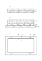
- the first laminate FIG.
- the embossed release sheet 56 and the pressure-sensitive adhesive layer 55 formed on the surface thereof obtained by the method disclosed in Patent Document 2 is: Before being attached to an adherend, a foam layer 57 is provided to form a second laminated body, and then, as shown in FIGS. 5B and 5C, the second laminated body is a second laminated body.
- the body embossed release sheet 56 is replaced with a smooth release sheet 58 provided with a positioning mark 59 for precise attachment to the back surface of the display to form a third laminated body. Then, the third stacked body is punched into a desired shape and attached to the back surface (attachment surface) of the display.
- the unevenness formed by transferring the embossing is lost due to the flow of the adhesive, and as a result, the third laminate ( Bubbles sometimes remained between the third laminate (adhesive tape) and the adherend when the adhesive tape was attached. That is, in the pressure-sensitive adhesive tape obtained by the method disclosed in Patent Document 2, it is essential to peel off the embossed release sheet 56 in order to attach the smooth release sheet 58 for attachment to an adherend, Due to the peeling, there is a problem that the unevenness formed by the embossing of the pressure-sensitive adhesive layer 55 is not sufficiently retained.
- the present invention prevents an air bubble from remaining between the adhesive tape and the adherend when applying the adhesive tape, and can secure the airtightness of the adherend, and such an adhesive tape. It is an object of the present invention to provide a method for producing an adhesive tape for producing.
- a pressure-sensitive adhesive tape comprising a foam layer and a pressure-sensitive adhesive layer provided on one surface of the foam layer,
- the foam layer has, on one surface, a concave portion that is recessed from the surface, The recess opens at the end of the foam layer,
- the pressure-sensitive adhesive layer is located on one side of the recess of the foam layer, and has a recess-corresponding portion recessed from the surface of the pressure-sensitive adhesive layer on one side, The depth of the said recessed part of the said foam layer is larger than the thickness of the said adhesive layer,
- the adhesive tape characterized by the above-mentioned.
- an adhesive tape that prevents air bubbles from remaining between the adhesive tape and an adherend at the time of applying the adhesive tape, and can ensure airtightness of the adherend, and such an adhesive tape It is possible to provide a method for producing an adhesive tape for producing the.
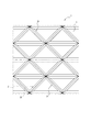
- FIG. 2 is a plan view schematically showing the pressure-sensitive adhesive tape shown in FIG. 1 in a state where a release sheet is not provided, as seen from the pressure-sensitive adhesive surface side to an adherend.
- FIG. 6 is a plan view schematically showing a modified example of the adhesive tape shown in FIG. 1 in a state where a release sheet is not provided, as viewed from the adhesive surface side to an adherend.
- (A) is a cross-sectional view schematically showing a first laminate of an embossed release sheet 56 and a pressure-sensitive adhesive layer 55 formed on the surface thereof, which is obtained by the method disclosed in Patent Document 2. ..
- the embossed release sheet 56 of the second laminate is precisely bonded to the back surface (adherend) of the display for the second laminate in which the foam layer 57 is provided on the first laminate.
- FIG. 6 is a partially enlarged cross-sectional view schematically showing a cross section at a position where an emboss is formed, for the embossed release sheet a produced in Production Example 1.
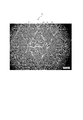
- 3 is a photograph (observed with an optical microscope) of the pressure-sensitive adhesive tape of Example 3 taken in a state in which a release sheet is not provided, taken from the pressure-sensitive adhesive surface side to an adherend.
- the pressure-sensitive adhesive tape 1 of the present embodiment is not particularly limited, but can be used, for example, in an electronic device, and specifically, an electronic device having a display unit among the electronic devices, in particular, a personal computer, a digital video camera, an electronic notebook, and a mobile phone.
- a mobile electronic terminal such as a telephone, a smartphone, a game machine, and an electronic book, it can be used on the back surface of a display which is a display unit.
- the pressure-sensitive adhesive tape 1 of the present embodiment includes a foam layer 2 and a pressure-sensitive adhesive layer 3 provided on one surface of the foam layer 2 in the cross-sectional view shown in FIG.
- the surface on one side (the surface on the side opposite to the surface on which the foam layer 2 is adhered) is an adhesive surface on the adherend.
- the release sheet 4 may be provided on the adhesive surface of the adhesive layer 3 for storage before use of the adhesive tape 1.
- the “adhesive surface” means the surface opposite to the surface of the pair of surfaces of the adhesive layer 3 that is adhered to the foam layer 2 (peeling when the release sheet 4 is provided. This is the surface that is attached to the sheet 4), that is, the surface that is attached to the adherend of the adhesive tape 1.
- the side attached to the adherend is defined as one side, and the side opposite to the one side is defined as the other side.
- the pressure-sensitive adhesive tape 1 is a sheet-like structure in which the layers of the pressure-sensitive adhesive tape 1 are laminated in a plan view, and the foam layer 2 and the pressure-sensitive adhesive layer 3 of the pressure-sensitive adhesive tape 1 are laminated.
- the total thickness can be 1,200 ⁇ m or less. Further, the total thickness is preferably 30 to 250 ⁇ m, more preferably 50 to 200 ⁇ m, and further preferably 50 to 150 ⁇ m.
- the adhesive tape 1 having such a thickness has high flexibility, and bubbles tend to remain between the adhesive tape 1 and the adherend during sticking, which tends to cause wrinkles.
- the effect of the pressure-sensitive adhesive tape 1 can be exhibited more preferably.
- the above-mentioned thickness of the adhesive tape 1 is measured by a method using a dial gauge according to JIS K6250. Specifically, a dial gauge whose contact surface with the adhesive tape 1 is a flat surface having a diameter of 8 mm is 0.51 N It is a value measured when they are contacted with each other. Note that the thickness does not include the thickness of the release sheet 4. Further, for example, it can be measured using a thickness meter FFG-6 manufactured by Ozaki Seisakusho.
- the adhesive strength of the pressure-sensitive adhesive tape 1 of the present embodiment is preferably 1 to 20 N/20 mm, more preferably 2 to 20 N/20 mm, further preferably 3 to 20 N/20 mm, and even more preferably 4 -18 N/20 mm, particularly preferably 5-18 N/20 mm.
- the adhesive force is a value measured according to JIS Z0237. Specifically, the adhesive force is obtained by stacking the pressure-sensitive adhesive layer 3 of the pressure-sensitive adhesive tape 1 and a clean and smooth stainless steel plate (BA plate), and reciprocating once on the back surface of the pressure-sensitive adhesive tape 1 using a 2 kg roller. Pressurize with.
- the laminated body after the pressurization is left for 1 hour under the condition of the temperature of 23° C. and the humidity of 50% RH, and the adhesive tape 1 is peeled off in the direction of 90° at a speed of 0.3 m/min.
- the adhesive force is a value measured when the adhesive tape 1 is peeled off.
- the adhesive tape 1 of the present embodiment preferably has a holding force of 2 mm or less, more preferably 0.5 mm or less, and further preferably 0.1 mm or less.
- the holding force refers to a value measured according to JIS Z0237.
- the holding power is obtained by stacking the pressure-sensitive adhesive layer 3 of the pressure-sensitive adhesive tape 1 and a clean and smooth stainless steel plate (hairline), and reciprocating the back surface of the pressure-sensitive adhesive tape 1 once using a 2 kg roller. Pressurize.
- the laminated body after the pressurization is left for 1 hour under the conditions of a temperature of 23° C. and a humidity of 50% RH, and then used as a test piece.
- the stainless plate constituting the test piece was fixed in the vertical direction, and a load of 100 g was applied to the lower end portion of the adhesive tape 1 constituting the test piece. Then, it is a value obtained by measuring the displacement distance between the stainless steel plate and the adhesive tape 1 with a caliper after leaving it in that state for 24 hours.
- the adhesive tape 1 is provided with a foam layer 2 on the other side of the adhesive layer 3 as shown in FIG. 1, and due to its cushioning property, for example, an impact on an adherend. It is possible to prevent the occurrence of defects.
- the foam layer 2 has a sheet shape in a plan view, and can have substantially the same size as the adhesive layer 3 of the adhesive tape 1 in a plan view.
- the foam layer 2 has a concave portion 21 recessed from the surface on the surface (one surface) on the side of the pressure-sensitive adhesive layer 3, and as shown in FIG.
- the recess 21 is open at the end of the foam layer 2.
- the recess 21 is recessed from the surface of the foam layer 2 on the pressure-sensitive adhesive layer 3 side, and the pressure-sensitive adhesive layer 3 can enter the recess 21.
- the concave portion 21 extends, for example, in a linear shape or a curved shape (a linear shape in the illustrated example) on the surface of the foam layer 2 on the pressure-sensitive adhesive layer 3 side, and the concave portion is seen in a plan view.
- At least one end (both ends in the illustrated example) of 21 is open to the end of the foam layer 2. Furthermore, a plurality of recesses 21 can be provided on the surface of the foam layer 2. Arrangement of the concave portion 21 can be arbitrary. For example, in the case where the vertical direction of FIG. 2 is the manufacturing direction of the adhesive tape 1, the concave portion 21 is provided so as to be inclined with respect to the manufacturing direction in plan view. Alternatively, as shown in the modified example of FIG. 3, when the vertical direction of FIG. 3 is the manufacturing direction of the adhesive tape 1 as in FIG. 2, the concave portion 21 that is inclined with respect to the manufacturing direction or the concave portion that is orthogonal to the manufacturing direction in plan view. 21 may be provided.
- the method of forming the recess 21 of the foam layer 2 is not particularly limited, and for example, when manufacturing the foam layer, a mold having a protrusion corresponding to the shape of the recess 21 (metal, resin, paper It can also be formed by shaving the surface of the foam layer having no recess, pressing, or the like.
- the pressure-sensitive adhesive tape 1 is provided with the pressure-sensitive adhesive layer 3 on the pressure-sensitive adhesive surface side of the foam layer 2 (one surface).
- the pressure-sensitive adhesive layer 3 has a sheet shape in a plan view, and can have substantially the same size as the foam layer 2 of the pressure-sensitive adhesive tape 1 in a plan view.
- the pressure-sensitive adhesive layer 3 has a recess-corresponding portion 31 located on one side of the recess 21 of the foam layer 2 and recessed from the surface of the pressure-sensitive adhesive layer 3 on one side.
- the recess-corresponding portion 31 is a portion of the adhesive layer 3 that can enter the inside of the recess 21 of the foam layer 2, and can enter the inside of the recess 21 and form the recess 21.
- the shape follows the inner surface.
- the recess-corresponding portion 31 projects more toward the foam layer 2 side (the other side) than the surrounding portion of the portion 31.
- the one-side surface of the recess-corresponding portion 31 is recessed from the one-side surface of the adhesive layer 3 around the recess-corresponding portion 31. Then, when the adhesive tape 1 is attached to the adherend, a flow path is formed between the concave portion corresponding portion 31 of the adhesive tape 1 and the adherend.
- the pressure-sensitive adhesive layer 3 has the recess-corresponding portion 31 located on one side of the recess 21 of the foam layer 2, as shown in FIG. 3 is open at the end and extends in the same shape as the recess 21 of the foam layer 2.
- the depth 2D of the recess 21 of the foam layer 2 and the thickness 3T of the pressure-sensitive adhesive layer 3 are the depth 2D of the recess 21 of the foam layer 2 as shown in FIG.
- the thickness of the agent layer 3 is larger than 3T.
- the foam layer 2 side (the other side) of the surface of one side of the recessed portion corresponding portion 31 of the pressure-sensitive adhesive layer 3 is the most. ) Is located closer to the foam layer 2 (the other side) than the surface of the foam layer 2 (the surface other than the recess 21 ).
- the foam layer 2 has a concave portion 21 recessed from the surface on the pressure-sensitive adhesive layer 3 side surface, and the concave portion 21 opens at an end of the foam layer 2 to form a pressure-sensitive adhesive layer.
- 3 has a recess-corresponding portion 31, and the depth 2D of the recess 21 of the foam layer 2 is larger than the thickness 3T of the pressure-sensitive adhesive layer 3, whereby the pressure-sensitive adhesive tape 1 and the adherend are adhered when the pressure-sensitive adhesive tape 1 is attached. It is possible to prevent air bubbles from remaining between and, and to ensure the airtightness of the adherend after attachment.
- the foam layer 2 of the pressure-sensitive adhesive tape 1 has the concave portion 21, the concave portion 21 is opened at the end of the foam layer 2, and the pressure-sensitive adhesive layer 3 is By having the recess-corresponding portion 31, the recess-corresponding portion 31 has a concave shape, and the recess-corresponding portion 31 is opened at the end of the pressure-sensitive adhesive layer 3. Further, since the depth 2D of the concave portion 21 of the foam layer 2 is larger than the thickness 3T of the pressure-sensitive adhesive layer 3, a sufficient size between the pressure-sensitive adhesive tape 1 and the adherend when the pressure-sensitive adhesive tape 1 is attached. It is possible to prevent bubbles from remaining by forming the flow path of.
- the recessed shape of the concave portion corresponding portion 31 is not formed by, for example, the discontinuous adhesive layer 53 shown in FIG. Since it is formed by the layer 3, the pressure-sensitive adhesive of the pressure-sensitive adhesive layer 3 can appropriately flow after the pressure-sensitive adhesive tape 1 is attached. As a result, even if there is a flow path between the adhesive tape 1 and the adherend at the time of application, the flow path is closed by applying pressure or the like to the adhesive tape 1 after application, and the application after application is completed. The airtightness of the body can be secured. Further, in the present embodiment, the concave shape of the concave portion corresponding portion 31 is secured by the concave portion 21 of the foam layer 2, and for example, as shown in FIG.
- the concave shape of the adhesive layer 55 is secured. Since it is different from the state in which there is not, the concave shape of the concave portion corresponding portion 31 (the concave shape of the surface of the adhesive tape 1) is maintained over time. As described above, according to the pressure-sensitive adhesive tape 1 of the present embodiment, bubbles are prevented from remaining between the pressure-sensitive adhesive tape 1 and the adherend when the pressure-sensitive adhesive tape 1 is attached, and the airtightness of the adherend after attachment is improved. Can be secured.
- the cross-sectional shape of the surface inside the recess 21 is not particularly limited and may be any shape.
- the cross-sectional shape in addition to a shape in which one or more corners are present in the concave portion 21 by connecting a plurality of straight lines in a cross-sectional view (for example, a V shape as in the illustrated example), only a curve or a straight line
- the shape can be a combination with a curve (for example, U-shape, arc-shape).
- the pressure-sensitive adhesive layer 3 can easily form the concave shape of the concave portion corresponding portion 31 corresponding to the concave portion 21 of the foam layer 2 (for example, the foam layer 2).
- the width of the recess 21 in a cross-sectional view (the direction parallel to the surface of the foam layer 2 in a plan view) (The length in the direction orthogonal to the extending direction of the) does not have a portion that gradually increases from the opening of the recess 21 toward the bottom.
- the angle formed between the inner surface of the recess 21 and the surface of the foam layer 2 at the opening of the recess 21 is preferably more than 90°, more preferably 100 to 175°, and further preferably. It is 110 to 170°. By setting it in this range, the recessed shape of the recessed portion corresponding portion 31 of the pressure-sensitive adhesive layer 3 can be easily formed appropriately.
- the width 2W of the recess 21 is preferably 5 to 1000 ⁇ m, more preferably 20 to 500 ⁇ m, and further preferably 50 to 200 ⁇ m.
- the width 2W is preferably 5 to 1000 ⁇ m, more preferably 20 to 500 ⁇ m, and further preferably 50 to 200 ⁇ m.
- the width 2W of the recess 21 is a length measured at the opening of the recess 21 on the surface of the foam layer 2 in a cross-sectional view in a direction orthogonal to the extending direction of the recess 21, and
- the depth 2D described below means, in the same cross-sectional view, from the surface of the foam layer 2 in which the recess 21 is provided to the bottom of the recess 21 in a direction orthogonal to the surface (the laminating direction of the flame-retardant tape).
- the length is measured by the method described below and can be measured by the method described in Examples below.
- the pressure-sensitive adhesive tape After immersing the pressure-sensitive adhesive tape in liquid nitrogen for 1 minute, the pressure-sensitive adhesive tape was bent in liquid nitrogen using tweezers with the direction perpendicular to the extending direction of the concave portion of the pressure-sensitive adhesive tape as a crease to divide the pressure-sensitive adhesive tape in the thickness direction. Ten pieces for cross-section observation are prepared. After returning the slice to room temperature in a desiccator, the slice is fixed on a sample stand so that an electron beam is perpendicularly incident on the fractured surface, and the fractured surface is observed using an electron microscope.
- the depth of the recessed portion for this one piece is a value obtained by measuring the length from the surface of the foam layer in the cross section to the bottom of the recessed portion along the stacking direction.
- the width of the concave portion for the above-mentioned one piece is a value obtained by measuring the length from one end to the other end at the opening of the foam layer, and one end and the other end at the opening have the same cross section. It is a value obtained by multiplying the depth of the recess obtained in (1) by 0.95, and is a position on the inner surface of the recess which is separated from the bottom of the recess to one side in the stacking direction.
- the depth 2D of the recess 21 is preferably 1 to 100 ⁇ m, more preferably 3 to 50 ⁇ m, and further preferably 5 to 30 ⁇ m.
- the depth 2D is preferably 1 to 100 ⁇ m, more preferably 3 to 50 ⁇ m, and further preferably 5 to 30 ⁇ m.
- the recesses 21 may have the same surface cross-sectional shape, width, depth, or the like within one recess 21 or among a plurality of recesses 21. ..
- the ratio of the thickness 3T of the pressure-sensitive adhesive layer 3 to the depth 2D of the recess 21 of the foam layer 2 is preferably 10 to 99%, more preferably 15 to 85%. is there.
- the ratio is preferably 10 to 99%, more preferably 15 to 85%. is there.
- the thickness 3T of the pressure-sensitive adhesive layer 3 is a length measured along a direction orthogonal to the surface of the foam layer 2 (a laminating direction of the pressure-sensitive adhesive tape 1) at a position other than the recess-corresponding portion 31 of the pressure-sensitive adhesive layer 3. That is, it can be measured by the method of Examples described later.
- the area occupied by the recess-corresponding portion 31 on the surface of the pressure-sensitive adhesive layer 3 on the pressure-sensitive adhesive surface side can be arbitrary, but on the surface of the pressure-sensitive adhesive layer 3 on the pressure-sensitive adhesive surface side.
- the ratio of the area occupied by the concave portion corresponding portion 31 is preferably 1 to 90%, more preferably 3 to 50%, and further preferably 5 to 30%.
- the above-mentioned ratio is the ratio of the area occupied by the recesses 21 existing in the range of 5 ⁇ 5 cm on the adhesive surface side of the pressure-sensitive adhesive layer 3, and can be measured by observing the pressure-sensitive adhesive layer 3 with an optical microscope. it can.
- the thickness 3T of the pressure-sensitive adhesive layer 3 is not particularly limited, but is preferably 0.5 to 30 ⁇ m, more preferably 1 to 20 ⁇ m, and most preferably 2 to 15 ⁇ m. .. By setting the thickness to 3T, the adhesiveness of the adhesive tape 1 can be further ensured.
- the thickness 3T of the pressure-sensitive adhesive layer 3 means, in a cross-sectional view, from the surface of one side of the pressure-sensitive adhesive layer 3 to the surface of the other side along the direction orthogonal to the surface (the laminating direction of the flame-retardant tape). The measured length can be measured by the method of Examples described later.
- the foam layer 2, the pressure-sensitive adhesive layer 3, and the optional release sheet 4 of this embodiment will be described below.
- the thickness of the foam layer 2 is not particularly limited, but is preferably 250 ⁇ m or less, more preferably 30 to 200 ⁇ m, further preferably 50 to 150 ⁇ m.
- the foam layer 2 having a thickness within the above range the pressure-sensitive adhesive tape 1 can be thinned while obtaining cushioning properties. Further, even when no hole or the like is provided in a part of the adhesive tape 1, air bubbles can be easily removed from between the adhesive layer 3 and the adherend, and as a result, the adhesive tape 1 It is more preferable because it is possible to more effectively prevent poor appearance due to swelling and the like, and performance deterioration such as cushioning properties and adhesive strength.
- the 25% compressive strength of the foam layer 2 is preferably 0.003 to 1 MPa, more preferably 0.01 MPa to 0.5 MPa, and further preferably 0.02 MPa to 0.4 MPa. It is particularly preferable to use the one in the above range in order to obtain the pressure-sensitive adhesive tape 1 having cushioning properties and suitable followability with respect to the adherend.
- the foam of the foam layer 2 is not particularly limited, but examples thereof include polyolefin foam including polyethylene, polypropylene, ethylene-propylene copolymer, ethylene-vinyl acetate copolymer, polyurethane foam, acrylic foam. It is possible to use a rubber-based foam containing a body or other elastomer. Among them, as the foam, an acrylic foam is preferable because it is excellent in point impact absorption required for protection of a display part of an electronic device, such as a flexible display.
- the raw material of the acrylic foam includes, for example, an acrylic emulsion, a foaming agent (anionic surfactant), water as a dispersion medium, a cross-linking agent and other additives (the foam used in the foaming step).
- a foaming agent anionic surfactant
- water as a dispersion medium
- a cross-linking agent and other additives (the foam used in the foaming step).
- the gas for use will be described in the foaming process).
- An acrylic emulsion is an aqueous dispersion of an acrylic resin, and as a method for producing the same, a (meth)acrylic acid ester-based monomer is essential in the presence of a polymerization initiator, and optionally an emulsifier and a dispersion stabilizer. It can be obtained by copolymerizing the above-mentioned polymerizable monomer component and optionally a mixture of other polymerizable monomers copolymerizable with these monomers. Two or more acrylic emulsions may be used in combination.
- Examples of the polymerizable monomer that can be used to prepare the acrylic emulsion include methyl (meth)acrylate, ethyl (meth)acrylate, propyl (meth)acrylate, butyl (meth)allylate, and (meth ) Hexyl acrylate, heptyl (meth)acrylate, octyl (meth)acrylate, octadecyl (meth)acrylate, 2-ethylhexyl (meth)acrylate, cyclohexyl (meth)acrylate, nonyl (meth)acrylate, ( (Meth)acrylic acid such as dodecyl (meth)acrylate, stearyl (meth)acrylate, isobornyl (meth)acrylate, dicyclopentanyl (meth)acrylate, phenyl (meth)acrylate, benzyl (meth)acrylate, etc.
- Ester-based monomers acrylic acid, methacrylic acid, ⁇ -carboxyethyl(meth)acrylate, 2-(meth)acryloylpropionic acid, crotonic acid, itaconic acid, maleic acid, fumaric acid, itaconic acid half ester, maleic acid half Unsaturated bond-containing monomer having a carboxyl group such as ester, maleic anhydride and itaconic anhydride; glycidyl group-containing polymerizable monomer such as glycidyl (meth)acrylate and allyl glycidyl ether; 2-hydroxyethyl (meth) Hydroxyl group-containing polymerizable monomers such as acrylate, 2-hydroxypropyl (meth)acrylate, polyethylene glycol mono(meth)acrylate, glycerol mono(meth)acrylate; ethylene glycol di(meth)acrylate, 1,6-hexanediol di (Meth)acrylate,
- an emulsifier is used when preparing an acrylic emulsion, a known emulsifier may be used.
- the acrylic emulsion preferably has a viscosity of 5,000 to 20,000 mPa ⁇ s as measured by a Brookfield viscometer (25° C.), and more preferably 8,000 to 15,000 mPa ⁇ s. If the viscosity is 5,000 or more, the foam retaining force at the time of molding becomes sufficient, and finer cells can be molded. When the viscosity is 20,000 or less, the shearing force applied to the raw material during molding can be reduced, so that it is possible to prevent the cell having a distorted shape from being molded.
- Water is an essential component for the dispersion medium of the acrylic emulsion, but it may be a mixture of water and a water-soluble solvent.
- the water-soluble solvent include alcohols such as methyl alcohol, ethyl alcohol, isopropyl alcohol, ethyl carbitol, ethyl cellosolve, and butyl cellosolve, polar solvents such as N-methylpyrrolidone, and one or more of them. You may use the mixture etc. of.
- the acrylic emulsion can contain an anionic surfactant (foaming anionic surfactant) as a foaming agent of the emulsion composition.
- anionic surfactant include, for example, sodium laurate, sodium myristate, sodium stearate, ammonium stearate, sodium oleate, potassium oleate soap, castor oil potassium soap, palm oil potassium soap, lauroyl sarcosine.
- the anionic surfactant used in the present embodiment has an HLB of preferably 10 or more, more preferably 20 or more, and more preferably 30 or more in order to facilitate dispersion in the emulsion composition. Is particularly preferable.
- the acrylic emulsion can further contain an amphoteric surfactant in addition to the above anionic surfactant, whereby the bubbles can be made fine and uniform.
- an anionic surfactant and an amphoteric surfactant are used together, the charge of the hydrophilic group between the molecules of the anionic surfactant repels, and the molecules of the anionic surfactant are kept at a certain distance.
- the electrically neutral double-sided surfactant enters between the molecules of the anionic surfactant, whereby the bubbles can be more stabilized and the size of the bubbles can be reduced. Therefore, it is preferable to use the anionic surfactant and the amphoteric surfactant in combination.
- amphoteric surfactant is not particularly limited, and amino acid type, betaine type, amine oxide type and other amphoteric surfactants can be used. Betaine-type amphoteric surfactants are preferable because they have higher effects described above. Further, from the viewpoint of easy penetration of the anionic surfactant into the molecule, C10-12 compounds are preferable.
- amino acid type amphoteric surfactants include N-alkyl or alkenyl amino acids or salts thereof.
- the N-alkyl or alkenyl amino acid has an alkyl group or an alkenyl group bonded to a nitrogen atom, and further has one or two “—R—COOH” (wherein R represents a divalent hydrocarbon group, preferably It is an alkylene group, and particularly preferably has 1 to 2 carbon atoms).
- R represents a divalent hydrocarbon group, preferably It is an alkylene group, and particularly preferably has 1 to 2 carbon atoms.
- R represents a divalent hydrocarbon group, preferably It is an alkylene group, and particularly preferably has 1 to 2 carbon atoms.
- R represents a divalent hydrocarbon group, preferably It is an alkylene group, and particularly preferably has 1 to 2 carbon atoms.
- R represents a divalent hydrocarbon group, preferably It is an alkylene group, and particularly preferably has 1 to 2 carbon atoms.
- amphoteric surfactant any of these mono-forms and di-forms can be used.
- the alkyl group or alkenyl group may be linear or branched.
- Specific examples of the amino acid-type amphoteric surfactant include sodium lauryldiaminoethylglycine, sodium trimethylglycine, sodium cocoyl taurine, sodium cocoyl methyl taurate, sodium lauroyl glutamate, potassium lauroyl glutamate, and lauroyl methyl- ⁇ -alanine.
- betaine-type amphoteric surfactants include alkyl betaine, imidazolinium betaine, carbobetaine, amidocarbobetaine, amidobetaine, alkylamidobetaine, sulfobetaine, amidosulfobetaine, phosphobetaine, and the like.
- lauryl betaine lauryl betaine, stearyl betaine, lauryl dimethylaminoacetic acid betaine, stearyl dimethylaminoacetic acid betaine, lauric acid amidopropyl dimethylaminoacetic acid betaine, isostearic acid amide ethyldimethylaminoacetic acid betaine, Isostearic acid amidopropyl dimethylaminoacetic acid betaine, isostearic acid amidoethyl diethylaminoacetic acid betaine, isostearic acid amidopropyl diethylaminoacetic acid betaine, isostearic acid amidoethyldimethyldimethylaminohydroxysulfobetaine, isostearic acid amidopropyldimethylaminohydroxysulfobetaine, isostearic acid amidoethyldiethylamino Hydroxysulfobetaine
- amine oxide type amphoteric surfactant examples include lauryl dimethyl amine-N-oxide and oleyl dimethyl amine-N-oxide.
- betaine-type amphoteric surfactants are preferably used, and among betaine-types, alkyl betaine, imidazolinium betaine, and carbobetaine are particularly preferable.
- alkyl betaine include stearyl betaine and lauryl betaine
- imidazolinium betaine include 2-alkyl-N-carboxymethyl-N-hydroxyethyl imidazolinium betaine.
- the acrylic emulsion can contain a crosslinking agent as a curing agent. This makes it possible to improve the strength of the foam.
- a cross-linking agent is not particularly limited, and may be added in a necessary amount depending on the application and the like. Examples of the cross-linking method using a cross-linking agent include physical cross-linking, ionic cross-linking, and chemical cross-linking, and the cross-linking method can be selected according to the type of the water-dispersible resin.
- cross-linking agent known cross-linking agents can be used, and epoxy-based cross-linking agents, melamine-based cross-linking agents, isocyanate-based cross-linking agents, carbodiimide-based cross-linking agents, oxazoline-based cross-linking agents, etc.
- An appropriate amount can be used depending on the type of group and the amount of functional group.
- Epoxy cross-linking agents and isocyanate cross-linking agents are preferable in order to improve the adhesive strength, tack strength and delamination strength.
- the isocyanate-based and epoxy-based cross-linking agents can prevent material destruction of the adherend and the porous foam by increasing the material strength. Of these, aliphatic isocyanate is more preferable. Two or more kinds of these cross-linking agents may be used in combination.
- An acrylic emulsion is a surfactant for dispersing a water-dispersible resin, which is a surfactant for dispersing a water-dispersible resin (unlike an anionic surfactant, it may not have an effect as a foaming agent). Can be included. Such a surfactant may be appropriately selected depending on the selected water-dispersible resin.
- the blending amount of the water-dispersible resin (solid content) with respect to the liquid medium is preferably 30 to 80 parts by mass with respect to 100 parts by mass of the liquid medium. By setting it as such a range, the effect that a stable foamed body can be shape
- the compounding amount and the compounding ratio are based on the solid content, and the component constituting the “solid content” is a component excluding the dispersion medium from the emulsion. Specifically, it contains a resin, a surfactant, a filler, and the like.
- the content of the anionic surfactant is preferably 1.0 to 10 parts by mass, based on the total amount of the emulsion in the emulsion composition (the total of the solid content and the non-solid content is 100 parts by mass). 3 to 10 parts by mass is more preferable. With such a range, it is possible to obtain an effect that proper foaming is facilitated and a fine cell structure can be molded.
- the amount of the amphoteric surfactant is preferably 0.5 to 10 parts by mass, based on the total amount of the emulsion in the emulsion composition (the total of the solid content and the non-solid content is 100 parts by mass). It is more preferably 1 to 5 parts by mass. With such a range, it is possible to obtain an effect that proper foaming is facilitated and a fine cell structure can be molded.
- the amount of the cross-linking agent (curing agent) to be compounded is such that the mass ratio of the cross-linking agent to the acrylic emulsion (solid content) (crosslinking agent/acrylic emulsion) in the emulsion composition is 0.01 to 0.12. is there. It is preferably 0.025 to 0.05. By setting the content in such a range, a foam having a small residual compression strain can be molded.
- the method for producing an acrylic foam comprises a raw material preparing step, a foaming/curing step (foaming an emulsion composition containing at least an emulsion and a foaming agent using a mechanical floss method to form a foam, Curing the foam).
- the emulsion composition may further contain a cross-linking agent, and in the above step, the foam may be cured by applying energy to cross-link the resin constituting the emulsion through the cross-linking agent.
- an emulsion composition that is a raw material mixture of a foam is prepared by mixing the raw materials as described above.
- the mixing method at this time is not particularly limited, but for example, mixing may be performed while stirring in a container such as a mixing tank for mixing the respective components.
- a predetermined foaming gas is added to the emulsion composition obtained in the above raw material preparation step, and these are mixed sufficiently so that a large number of bubbles are present in the emulsion composition (foaming emulsion composition ).
- This foaming/curing step is usually carried out by thoroughly mixing the raw material mixture of the liquid porous foam obtained in the raw material preparing step and the foaming gas with a mixing device such as a mixing head.
- the foaming gas mixed with the emulsion composition in the stirring/foaming step forms bubbles (cells) in the foam, and the expansion ratio and density of the resulting foam depend on the mixing amount of the foaming gas. Is decided.
- the density of the porous foam it is necessary to adjust the density of the desired porous foam and the volume of the raw material of the porous foam (for example, the internal volume of the mold into which the raw material of the porous foam is injected).
- the mass of the raw material for the porous foam may be calculated, and the amount of the foaming gas may be determined so that the desired volume is obtained with this mass.
- Air is mainly used as the type of foaming gas, but other inert gases such as nitrogen, carbon dioxide, helium, and argon can also be used.
- a mechanical floss (mechanical foaming) method can be used as the foaming method used in the method for preparing an acrylic foam produced using an acrylic emulsion.
- the mechanical floss method is a method in which air in the atmosphere is mixed with an agitating blade to stir the emulsion composition to foam the emulsion composition.
- a stirring device generally used in the mechanical froth method can be used without particular limitation, and for example, a homogenizer, a dissolver, a mechanical froth foaming machine or the like can be used.
- a porous foam having a density suitable for various applications can be obtained by adjusting the mixing ratio of the emulsion composition and air.
- the mixing time of the emulsion composition and air is not particularly limited, but is usually 1 to 10 minutes, preferably 2 to 6 minutes.
- the mixing temperature is not particularly limited, but it is usually room temperature.
- the stirring speed in the above mixing is preferably 200 rpm or more (more preferably 500 rpm or more) in order to make the bubbles fine, and 2000 rpm or less (800 rpm or less in order to smooth the discharge of the foamed product from the foaming machine. More preferable).
- the emulsion composition foamed as described above is formed into a sheet-shaped acrylic foam layer having a desired thickness by a known means such as a doctor knife or a doctor roll. ..
- the acrylic foam can be self-crosslinked, but the foam may be cured by applying energy to crosslink the resin constituting the emulsion via a crosslinking agent.
- the step of applying energy is not particularly limited, and examples thereof include a heating step (thermal crosslinking).
- the dispersion medium in the molded foamed emulsion composition is evaporated.
- the drying method at this time is not particularly limited, but hot air drying or the like may be used, for example.
- the drying temperature and the drying time are not particularly limited, but may be, for example, about 80° C. and about 1 to 3 hours.
- the dispersion medium evaporates from the foamed emulsion composition, but the passage when this vapor escapes is connected from the inside to the outside of the porous foam. Therefore, in this foam, the passages when water vapor escapes remain as open cells, so that at least a part of the cells present in the porous foam become open cells.
- the foaming gas mixed in the stirring/foaming step remains as it is, it will become closed cells in the obtained porous foam, and the mixed foaming gas will escape vapor in this step. When they are communicated with each other, they become open cells in the obtained porous foam. That is, a part of the cells in the porous foam are open cells, and the remaining cells are closed cells, which is a semi-open cell structure in which open cells and closed cells are mixed.
- the crosslinking (curing) reaction of the raw materials proceeds and completes in the heating process.
- the raw materials are cross-linked by the above-mentioned cross-linking agent to form a cured porous foam.
- the heating means at this time is not particularly limited as long as it can sufficiently heat the raw material and crosslink (cure) the raw material, but for example, a tunnel heating furnace or the like can be used.
- the heating temperature and the heating time may be any temperature and time capable of crosslinking (curing) the raw material, for example, 80 to 150° C. (particularly, about 120° C. is preferable) and about 1 hour. ..
- the peak temperature of the loss tangent of the pressure-sensitive adhesive layer 3 based on the dynamic viscoelastic spectrum measured at a frequency of 1 Hz is not particularly limited, but is preferably ⁇ 30 to 20° C. , -20 to 10°C, more preferably -10 to 5°C.
- a viscoelasticity tester (Rheometrics, trade name: Ares 2KSTD) is used, and a test piece is sandwiched between parallel disks, which are the measuring parts of the tester, and the storage elasticity at a frequency of 1 Hz.
- the modulus (G′) and the loss elastic modulus (G′′) are measured.
- the peak temperature refers to the peak temperature confirmed in the tan ⁇ spectrum for the measurement temperature range ( ⁇ 50° C. to 150° C.).
- the pressure-sensitive adhesive layer 3 having a thickness of 0.5 to 2.5 mm formed by using the pressure-sensitive adhesive used for forming the pressure-sensitive adhesive layer 3 can be used.
- the pressure-sensitive adhesive that constitutes the pressure-sensitive adhesive layer 3 preferably has a gel fraction of 10 to 60% by mass, more preferably 20 to 55% by mass, and further preferably 30 to 50% by mass.
- the gel fraction is in the above range, the surface shape of the pressure-sensitive adhesive layer 3 is more easily retained even if it is a thin film, and thus it is easy to prevent change over time, and the adherend and the pressure-sensitive adhesive layer 3 Bubbles can be easily removed from between.
- the gel fraction means a value measured by the following method.
- the pressure-sensitive adhesive layer 3 is formed by aging in an environment of 40° C. for 2 days.
- (2) A test piece is obtained by cutting the pressure-sensitive adhesive layer 3 into 50 mm ⁇ 50 mm.
- the test piece is immersed in toluene in an environment of 23° C. for 24 hours.
- the pressure-sensitive adhesive forming the pressure-sensitive adhesive layer 3 is not particularly limited, and examples thereof include acrylic pressure-sensitive adhesive, rubber pressure-sensitive adhesive, silicone pressure-sensitive adhesive, urethane pressure-sensitive adhesive, polyester pressure-sensitive adhesive, styrene-diene block copolymer pressure-sensitive adhesive.
- Known adhesives such as adhesives, vinyl alkyl ether-based adhesives, polyamide-based adhesives, fluorine-based adhesives, creep property improving adhesives, and radiation-curable adhesives can be used. It is preferable to use an acrylic pressure-sensitive adhesive as the pressure-sensitive adhesive because it has excellent adhesion reliability.
- acrylic pressure-sensitive adhesive one containing an acrylic polymer can be used.
- acrylic polymer those obtained by polymerizing a monomer component containing a (meth)acrylic monomer such as (meth)acrylic acid alkyl ester can be used.
- alkyl (meth)acrylate include methyl (meth)acrylate, ethyl (meth)acrylate, propyl (meth)acrylate, isopropyl (meth)acrylate, butyl (meth)acrylate, and (meth)acrylate.
- the (meth)acrylic acid alkyl ester it is preferable to use a (meth)acrylic acid alkyl ester having an alkyl group having 1 to 20 carbon atoms, and the alkyl group having 4 to 18 carbon atoms. It is more preferable to use the (meth)acrylic acid alkyl ester.
- the alkyl group include linear or branched alkyl groups.
- “(meth)acrylic acid alkyl ester” means acrylic acid alkyl ester or methacrylic acid alkyl ester.
- butyl (meth)acrylate as the (meth)acrylic acid alkyl ester having an acrylic group with 4 to 18 carbon atoms makes it easier to maintain the surface shape of the pressure-sensitive adhesive layer 3, and thus changes with time. It is easy to prevent the air bubbles, and bubbles can easily escape from between the adherend and the adhesive tape 1 (air releasing property).
- a monomer having a carboxyl group such as (meth)acrylic acid, itaconic acid, maleic acid, fumaric acid, crotonic acid, isocrotonic acid or an anhydride thereof; Monomers having sulfonic acid groups such as sodium vinyl sulfonate; Monomers having cyano groups such as acrylonitrile; Amide groups such as acrylamide, methacrylamide, N-vinylpyrrolidone, N,N-dimethyl(meth)acrylamide Monomers having; hydroxyalkyl (meth)acrylate, monomers having hydroxyl groups such as glycerin dimethacrylate; aminoethyl (meth)acrylate, monomers having amino groups such as (meth)acryloylmorpholine; cyclohexyl Monomers having imide groups such as maleimide and isopropylmaleimide; monomers having epoxy groups such as
- aromatic vinyl compounds such as styrene and substituted styrene; olefins such as ethylene, propylene and butadiene; vinyl esters such as vinyl acetate; vinyl chloride Etc. can also be used.
- An acrylic polymer can be produced by polymerizing a monomer by a solution polymerization method, a bulk polymerization method, a suspension polymerization method, an emulsion polymerization method, or the like. It is preferable because the production efficiency of the polymer is improved.
- the solution polymerization method includes, for example, a method in which a monomer, a polymerization initiator, and an organic solvent are mixed and stirred at a temperature of preferably 40 to 90° C., followed by radical polymerization.
- polymerization initiator examples include peroxides such as benzoyl peroxide and lauryl peroxide, azo thermal polymerization initiators such as azobisisobutylnitrile, acetophenone photopolymerization initiators, benzoin ether photopolymerization initiators, and benzyl.
- a ketal photopolymerization initiator, an acylphosphine oxide photopolymerization initiator, a benzoin photopolymerization initiator, a benzophenone photopolymerization initiator, or the like can be used.
- the acrylic polymer obtained by the above method may be in a state of being dissolved or dispersed in an organic solvent, for example, when it is produced by a solution polymerization method.
- acrylic polymer obtained by the above method those having a weight average molecular weight of 300,000 to 1.2 million are preferably used, and those having a weight average molecular weight of 400,000 to 1.1 million are more preferably used. It is preferable to use one having a weight average molecular weight of 500,000 to 1,000,000 in order to obtain the pressure-sensitive adhesive tape 1 having even better adhesive strength and easy removal of air bubbles even if it is a thin layer. ..
- the weight average molecular weight refers to a value measured by gel permeation chromatography (GPC method) and calculated in terms of standard polystyrene. Specifically, the weight average molecular weight can be measured under the following conditions using a GPC device (HLC-8329GPC) manufactured by Tosoh Corporation.
- a pressure-sensitive adhesive that can be used for forming the pressure-sensitive adhesive layer 3
- the tackifier resin include rosin-based tackifier resin, polymerized rosin-based tackifier resin, polymerized rosin ester-based tackifier resin, rosin phenol-based tackifier resin, stabilized rosin ester-based tackifier resin, and disproportionated rosin ester-based resin.
- a tackifier resin, a hydrogenated rosin ester tackifier resin, a terpene tackifier resin, a terpene phenol tackifier resin, and a petroleum resin tackifier resin such as a styrene tackifier resin can be used.
- the tackifying resin it is possible to use a combination of a rosin-based tackifying resin and a petroleum resin-based tackifying resin, and even if it is a thin layer, the pressure-sensitive adhesive tape is provided with more excellent adhesive force and easy removal of bubbles. It is preferable for obtaining 1.
- the rosin-based tackifying resin and petroleum resin-based tackifying resin are particularly preferably used in combination with the acrylic polymer, and an acrylic polymer obtained by polymerizing a monomer containing butyl (meth)acrylate. It is preferable to use them in combination in order to obtain the pressure-sensitive adhesive tape 1 which has a further excellent adhesive force even if it is a thin layer and is easy to remove air bubbles.
- the tackifying resin it is preferable to use a tackifying resin which is liquid at room temperature in order to further improve the initial adhesive force of the pressure-sensitive adhesive layer 3.
- the tackifying resin that is liquid at room temperature include low molecular weight liquid rubbers such as process oil, polyester plasticizer, and polybutene. Terpene phenol resin can be used.
- YP manufactured by Yasuhara Chemical Co., Ltd. can be used. -90 L and the like.
- the tackifying resin is preferably used in the range of 20 to 60 parts by mass, and more preferably in the range of 30 to 55 parts by mass with respect to 100 parts by mass of the acrylic polymer, because the adhesive force is more excellent. It is more preferable for obtaining the adhesive tape 1.
- the pressure-sensitive adhesive forming the pressure-sensitive adhesive layer 3 one containing a softening agent, a plasticizer, a filler, an antiaging agent, a colorant, etc., if necessary, in addition to the acrylic polymer or the like is used. can do.
- the pressure-sensitive adhesive it is possible to adjust the gel fraction of the pressure-sensitive adhesive layer 3 to a suitable range by using a crosslinking agent among the above, and as a result, it is easy to maintain the shape of the pressure-sensitive adhesive layer 3. Since it is easy to prevent changes over time, bubbles can be easily removed from between the adherend and the pressure-sensitive adhesive layer 3, and the pressure-sensitive adhesive tape 1 having excellent adhesive strength can be obtained. preferable.
- crosslinking agent for example, an isocyanate crosslinking agent or an epoxy crosslinking agent is preferably used.
- isocyanate crosslinking agent for example, tolylene diisocyanate, naphthylene-1,5-diisocyanate, hexamethylene diisocyanate, diphenylmethane diisocyanate, xylylene diisocyanate, trimethylolpropane-modified tolylene diisocyanate and the like can be used. It is preferred to use toluene diisocyanate adducts such as methylolpropane modified tolylene diisocyanate.
- the toluene diisocyanate adduct has a structure derived from toluene diisocyanate in the molecule, and examples of commercially available products include Coronate L (manufactured by Nippon Polyurethane Industry Co., Ltd.) and the like.
- an acrylic polymer having a hydroxyl group is, for example, 2-hydroxyethyl (meth)acrylate, 4-hydroxybutyl (meth)acrylate, 6-hydroxyhexyl (meth)acrylate, etc., as a monomer used in the production thereof. It can be used, and it is more preferable to use 2-hydroxyethyl (meth)acrylate and 4-hydroxybutyl (meth)acrylate.
- the epoxy cross-linking agent for example, Tetrad X or Tetrad C manufactured by Mitsubishi Gas Chemical Co., Inc., or E-05X manufactured by Soken Chemical Co., Ltd. can be used.
- the epoxy crosslinking agent it is preferable to use an acrylic polymer having an acid group as the acrylic polymer.
- Acrylic polymer having an acid group as a monomer used in its production, for example, (meth) acrylic acid, acrylic acid dimer, itaconic acid, crotonic acid, maleic acid, it is preferable to use maleic anhydride, More preferably, (meth)acrylic acid is used.
- the pressure-sensitive adhesive that can be used to form the pressure-sensitive adhesive layer 3 it is preferable to use a pressure-sensitive adhesive that contains a solvent as necessary.
- the pressure-sensitive adhesive it is preferable to use one having a viscosity adjusted to a range of 0.1 mPa ⁇ s to 1000 mPa ⁇ s, more preferably 1 mPa ⁇ s to 200 mPa ⁇ s, and further preferably It is adjusted in the range of 10 mPa ⁇ s to 100 mPa ⁇ s. Thereby, the pressure-sensitive adhesive layer 3 having a predetermined shape can be easily formed.
- the pressure-sensitive adhesive tape 1 of the present embodiment can further include a release sheet 4 provided on the pressure-sensitive adhesive layer 3 on the pressure-sensitive adhesive surface to the adherend.
- the release sheet 4 By including the release sheet 4, the adhesive surface side of the adhesive tape 1 can be protected.
- the release sheet 4 As the release sheet 4, as shown in FIG. 1, it is possible to use a sheet-shaped sheet having smooth both sides in a plan view. Further, the release sheet 4 may have substantially the same size as the foam layer 2 of the adhesive tape 1 in plan view.
- a smooth sheet as shown in FIG. 1 is used as the release sheet 4, a space is formed between the pressure-sensitive adhesive layer 3 and the release sheet 4 at a position corresponding to the recess 21, as shown in FIG.
- the surface shape of the release sheet 4 can be arbitrary.
- a shape corresponding to the recess 21 is provided at a position corresponding to the recess 21 of the foam layer 2.
- the release sheet 4 is not particularly limited as long as it has releasability with respect to the pressure-sensitive adhesive layer 3, but for example, a resin film coated with a release agent can be used.
- a resin film coated with a release agent can be used.
- the resin film a polyester film, a polyimide film, a polyolefin film or the like can be used.
- the polyethylene terephthalate film is preferable because it has good heat resistance and strength and is low in cost.
- the thickness of the resin film is not particularly limited, but is preferably 25 ⁇ m to 100 ⁇ m, more preferably 50 ⁇ m to 100 ⁇ m. Within the above range, unevenness of the foam layer 2 is less likely to occur when the foam layer 2 is formed, which is preferable.
- the release agent is not particularly limited, but a silicone-based release agent is preferable because the release force can be easily adjusted.
- a pressure-sensitive adhesive layer different from the pressure-sensitive adhesive layer 3 can be provided on the other surface of the foam layer 2, and the other side of the foam layer 2 can be further provided.
- a recess similar to the recess 21 may be provided on the side surface.
- the method for producing an adhesive tape according to the present embodiment is a method for producing the adhesive tape 1 according to the above-described embodiment of the present invention, in which the adhesive layer 3 is applied to the surface of the release sheet 4 to form a first laminate. A body is obtained, and then the foam layer 2 and the first laminated body are laminated.
- the method for manufacturing the pressure-sensitive adhesive tape includes a foam layer forming step of forming the foam layer 2 having the concave portion 21, the pressure-sensitive adhesive layer 3 being applied to the surface of the release sheet 4, and the first lamination.
- the raw material (the above emulsion composition or the like) for forming the foam layer 2 is, for example, a release paper (or a resin treated with a release treatment). Film).
- a release paper or a resin treated with a release treatment
- another release paper or a resin film subjected to a release treatment
- a roll coater or the like is passed through to adjust the thickness while foaming the raw material.
- the release paper supplied from the upper side does not matter, but when the release paper is used, the thickness of the foam layer before curing can be easily adjusted, and the foam layer obtained after the heat treatment is obtained.
- a skin layer can be formed on the surface of 2 (upper release paper side).
- the raw material is coated on the release paper by a known means such as a doctor knife or a doctor roll to obtain a desired material. Adjust to the thickness. Through these steps, a laminate having release paper laminated on at least one side of the foam layer before curing can be obtained. Then, this laminate is heated by a heat treatment device.
- the foam layer 2 can be formed by curing and drying.
- the foam layer 2 of the present embodiment has the concave portion 21, as one of the release papers laminated on the above-mentioned laminate, the convex portion corresponding to the concave shape for forming the concave portion 21 on the surface is formed.
- the recess 21 of the foam layer 2 can be formed by using a release paper having a portion.
- the foam layer 2 (without the concave portion 21) is manufactured using a smooth release paper (the convex portion for forming the concave portion 21 is not formed), and after removing the release paper, the surface of the foam layer 2 is removed. It is also possible to form the concave portion with, for example, a knife.
- the first laminated body forming step is a step of applying the adhesive forming the adhesive layer 3 to the surface of the release sheet 4 to obtain the first laminated body.
- the pressure-sensitive adhesive that forms the pressure-sensitive adhesive layer 3 is applied onto the release sheet 4 by a coating method such as a slot die coating method and dried to form the pressure-sensitive adhesive layer 3 on the release sheet 4. .. This makes it possible to obtain a first laminate in which the pressure-sensitive adhesive layer 3 and the release sheet 4 are laminated.
- the polymerizing step is a step of superposing the foam layer 2 and the first laminated body. Specifically, the surface of the foam layer 2 on which the recess 21 is formed, obtained in the foam layer forming step, and the pressure-sensitive adhesive layer 3 of the first laminate obtained in the first laminate forming step. Laminate them so that they face the surface of. Then, by using the roller or the like to compress the laminated body so that the foam layer 2 is crushed in the thickness direction, the pressure-sensitive adhesive layer 3 of the first laminated body is inside the concave portion 21 of the foam layer 2. It is possible to obtain the pressure-sensitive adhesive tape 1 which is attached to the surface and has the release sheet 4.
- the pressure-sensitive adhesive layer 3 is applied to the surface of the release sheet 4 to obtain a first laminated body, and then the foam layer 2 and the first laminated body are superposed to form the pressure-sensitive adhesive layer 3.
- the shape corresponding to the concave portion 21 of the foam layer 2 can be more appropriately facilitated.
- a good depression shape is formed on the pressure-sensitive adhesive surface of the concave portion corresponding portion 31.
- the shape corresponding to the recess 21 of the foam layer 2 can be easily formed in the pressure-sensitive adhesive layer 3 more appropriately.
- the pressure-sensitive adhesive tape according to the embodiment of the present invention does not have a release sheet
- the pressure-sensitive adhesive tape is manufactured by the pressure-sensitive adhesive tape manufacturing method of the present embodiment, and then the release sheet 4 is removed, for example. And the like.
- the adhesive tape of the present invention is not limited to the above examples, and can be modified as appropriate.
- the adhesive tape may be provided with a layer other than the foam layer and the adhesive layer described above.
- the pressure-sensitive adhesives a to c described below were applied to the release-treated surface of a polyester release sheet (Nippa Corporation, PET50 ⁇ 1J0L) having a thickness of 50 ⁇ m, and the thickness after drying. To have a thickness of 50 ⁇ m, the coated pressure-sensitive adhesive is dried in an environment of 100° C. for 3 minutes, and then aged in an environment of 40° C. for 2 days. Formed. A test piece was obtained by cutting the pressure-sensitive adhesive layer into a square having a length of 50 mm and a width of 50 mm.
- Dynamic viscoelasticity Adhesives a to c to be described later are each applied to the surface of a polyester release sheet (Nippa Corporation, PET50 ⁇ 1J0L) having a thickness of 50 ⁇ m so that the thickness after drying is 200 ⁇ m.
- the above-mentioned pressure-sensitive adhesive was applied to the above, the coated pressure-sensitive adhesive was dried in an environment of 100° C. for 3 minutes, and then aged in an environment of 40° C. for 2 days to form a pressure-sensitive adhesive layer.
- a plurality of laminates of the release sheet after the aging and the pressure-sensitive adhesive layer are prepared, and the pressure-sensitive adhesive layers of the two laminates are faced and overlapped with each other, and then one of the release sheets is peeled off to form the pressure-sensitive adhesive layer.
- a pressure-sensitive adhesive layer having a thickness of two layers was obtained.
- a test piece was prepared by stacking the pressure-sensitive adhesive layers on each other in the same manner until the total thickness became 2 mm. Next, using a viscoelasticity tester (Rheometrics, trade name: Ares 2KSTD), the test piece was sandwiched in a parallel disk-shaped measuring section having a diameter of 7.9 mm, a frequency of 1 Hz and a heating time of 1° C./1.
- the loss tangent tan ⁇ was calculated by the following calculation formula. Loss tangent tan ⁇ G′′/G′
- Measurement conditions/Objective lens 5x ⁇ Internal lens: 1.0x ⁇ Measurement CCD camera: 1/3'' ⁇ Wavelength filter: 530 White ⁇ Measurement range: 80 ⁇ m ⁇ Measurement mode: WaveM Next, using analysis software (manufactured by Ryoka System Co., Ltd., VS-Viewer), when the surface of the foam layer having the recesses is viewed from directly above, the recesses in the cross section orthogonal to the extending direction of the recesses are formed. The depth and width were analyzed.
- the depth and width of the recess are measured in a cross section at an arbitrary position, the same operation is performed at a total of 10 points, and the average value of each value is used as the depth and width of the recess in the present specification. did.
- the cross section orthogonal to the extending direction of the recessed portion is in the direction in which the width of the recessed portion described later is the minimum when the recessed surface of the foam layer is viewed from directly above (viewed from one side in the stacking direction). It was a cross section.
- the depth of the recess in this one cross section is a value obtained by measuring the length from the surface of the foam layer in the cross section to the bottom of the recess along the stacking direction.
- the width of the concave portion in the above one cross section is a value obtained by measuring the length from one end to the other end in the opening of the foam layer, and one end and the other end in the opening have the same cross section.
- a value obtained by multiplying the depth of the obtained recess by 0.95 is a position on the inner surface of the recess that is separated from the bottom of the recess on one side in the stacking direction.
- Embossing width and embossing height of the embossed release sheet The three-dimensional height of the embossed surface of the embossed release sheet is measured in the same manner as the measurement of the depth and width of the recess of the foam layer. I created a map. Next, using an analysis software (VS-Viewer manufactured by Ryoka System Co., Ltd.), the embossed surface is viewed from directly above (the direction orthogonal to the surface of the release sheet), and with respect to the extending direction of the embossed ridge line. The height and width of the embossment in the cross section orthogonal to each other were analyzed.
- the cross section orthogonal to the extending direction of the embossing is the width of the embossing described below when the embossed surface of the release sheet is viewed from directly above (viewed from the surface side in the direction orthogonal to the surface of the release sheet).
- the cross section was taken in the direction in which The emboss height for this one cross section is a value obtained by measuring the height from the surface of the release sheet to the apex of the emboss in the cross section in the direction orthogonal to the surface.
- the width of the emboss for the above-mentioned one cross section is a value obtained by measuring the length between a pair of starting points projecting from the surface of the release sheet, and the pair of projecting starting points is obtained in the same cross section.
- the value obtained by multiplying the obtained emboss height by 0.95 is the position on the surface of the emboss that is separated from the apex of the emboss to the sheet side in the direction orthogonal to the surface.
- the thickness of the foam layer and the pressure-sensitive adhesive layer in the pressure-sensitive adhesive tape was measured at 10 locations (portions other than the concave portions and the portions corresponding to the concave portions), and the arithmetic average value was taken as the thickness of each layer.
- the thickness of the foam layer is a length measured from the surface on one side to the surface on the other side of the foam layer along the laminating direction, and the thickness of the adhesive layer is the adhesive surface of the adhesive layer. It is the length measured from the surface on one side to the surface of the foam layer (the surface on the other side of the pressure-sensitive adhesive layer) along the laminating direction.
- the surface of the pressure-sensitive adhesive layer on which the recess-corresponding portion is located is viewed from directly above and is orthogonal to the extending direction of the recess-corresponding portion.
- the depth of the portion corresponding to the recess in the cross section was analyzed. Specifically, the depth of the concave portion corresponding portion in the cross section at an arbitrary position was measured, the same operation was performed at a total of 10 places, and the average value of each value was taken as the depth of the concave portion corresponding portion in the present specification. ..
- the cross section orthogonal to the extending direction of the recess corresponding portion has the minimum width of the recess corresponding portion when viewed from directly above the surface of the adhesive layer having the recess corresponding portion (as viewed from one side in the stacking direction).
- the cross section was taken in the direction.
- the depth of the recessed portion corresponding to this one cross section is a value obtained by measuring the length from the surface of the pressure-sensitive adhesive layer in the cross section to the bottom of the recessed portion along the stacking direction.
- the adhesive tape was attached to an acrylic plate and the presence or absence of air bubbles between the adhesive tape and the acrylic plate was observed. It was evaluated by Specifically, it carried out as follows. 1) The release sheets of the adhesive tapes obtained in Examples and Comparative Examples were peeled off, and a 50 ⁇ m-thick polyester release sheet (Nippa Co., Ltd., PET50 ⁇ 1J0L) was attached to the release sheet at 23° C. and 50% RH. The adhesive tape for evaluation was obtained by standing still for 7 days in the atmosphere.
- the pressure-sensitive adhesive tape for evaluation is cut into a length of 50 mm ⁇ width of 100 mm, the release sheet is peeled off, and a length of 70 mm ⁇ width of 150 mm ⁇ thickness of 2 mm of transparent acrylic is applied to the surface of the pressure-sensitive adhesive layer under an atmosphere of 23° C. and 50% RH. A plate was placed, and the transparent acrylic plate was left standing for 5 seconds under a load of 5 N to obtain a temporary sticking product. 3) Next, after reversing the temporary attachment, the laminate was obtained by pressurizing them by reciprocating the 2 kg roller once from the surface on the side of the adhesive tape. 4) Ten laminates were produced by the above method.
- the flow path blockage evaluation 1 of the pressure-sensitive adhesive layer of the pressure-sensitive adhesive tapes of Examples and Comparative Examples is as follows.
- a frame-shaped pressure-sensitive adhesive tape is attached to an acrylic plate as described below, and both sides are sandwiched between the acrylic plates, and then Was immersed in water and the state of water penetration was observed and evaluated.
- the release sheets of the adhesive tapes obtained in Examples and Comparative Examples were peeled off, and a 50 ⁇ m-thick polyester release sheet (Nippa Co., Ltd., PET50 ⁇ 1J0L) was attached to the release sheet at 23° C. and 50% RH.
- the adhesive tape for evaluation was obtained by standing still for 7 days in the atmosphere.
- a 140 ⁇ m thick double-sided tape (manufactured by DIC, #8810CH, which has a release sheet on one side) was carefully adhered to the foam layer side of the evaluation adhesive tape so that air bubbles did not enter, and then the outer shape was 100 mm in length ⁇ 50 mm in width and cut into a frame shape having a width of 10 mm to obtain a test tape.
- the release sheet on the double-sided tape side of the test tape is peeled off and carefully adhered to a first acrylic plate having a length of 102 mm ⁇ width of 51 mm ⁇ thickness of 2 mm so that air bubbles do not enter, thereby obtaining a laminate.
- the release sheet of the adhesive tape for evaluation in the laminate was peeled off, a second acrylic plate having a length of 102 mm, a width of 51 mm, and a thickness of 2 mm was laminated, and the four sides thereof were fixed with a double clip.
- the said 1st acrylic plate and the 2nd acrylic plate produced the test piece joined by the said frame-shaped test tape.
- the test piece was left standing still at a water depth of 1 m for 30 minutes in a state of being fixed with a double clip (according to JISC 0920 IPX7). 6) After the standing, the test piece was visually observed and evaluated according to the following evaluation criteria.
- the flow path blockage evaluation 2 of the pressure-sensitive adhesive layers of the pressure-sensitive adhesive tapes of Examples/Comparative Examples was carried out by attaching a frame-shaped pressure-sensitive adhesive tape to an acrylic plate as described below and applying a load, and then between the pressure-sensitive adhesive tape and the acrylic plate. It was evaluated by observing the presence or absence of the flow path. Specifically, it carried out as follows. 1) The release sheets of the adhesive tapes obtained in Examples and Comparative Examples were peeled off, and a 50 ⁇ m-thick polyester release sheet (Nippa Co., Ltd., PET50 ⁇ 1J0L) was attached to the release sheet at 23° C. and 50% RH.
- the adhesive tape for evaluation was obtained by standing still for 7 days in the atmosphere. 2) A test tape was prepared by cutting the pressure-sensitive adhesive tape for evaluation into a frame shape having an outer shape of 100 mm length ⁇ 50 mm width and a width of 10 mm. 3) An acrylic plate having a length of 102 mm, a width of 51 mm, and a thickness of 2 mm is placed on the surface of the pressure-sensitive adhesive layer that constitutes the test tape, and a weight of 5 N is placed on the acrylic plate for 30 seconds, and then the weight is removed. A laminated body was obtained. 4) The laminate was turned upside down, the adhesive tape side was reciprocated once with a 2 kg roller to press it, and then left standing at 23° C. for 24 hours to prepare a test piece.
- the surface of the polyethylene resin composition layer was embossed with the same pattern as the pattern formed by the recess-corresponding portion shown in FIG.
- the cross section of the portion where the emboss is located is formed by laminating the polyethylene resin composition layer 60 on a base material 62 on which an emboss 61 formed by embossing is formed.
- the embossed sheet was then left to stand at room temperature for 14 days for complete curing to obtain an embossed release sheet a.
- the emboss height was 13 ⁇ m and the emboss width was 80 ⁇ m.
- Embossed release sheet b A commercially available crosslinked low-density polyethylene resin composition (trade name: Wrinklon CH-750T, manufactured by Mitsubishi Chemical Corporation, MFR value: 25 g/10 minutes) was applied to a neutral paper having a thickness of 110.0 g/m 2. Using a T-die extruder, extrusion is performed at a temperature of about 220° C. for extrusion molding to a thickness of about 50 ⁇ m (resin layer formation), and immediately after that, embossing is performed on the resin layer surface by an embossing machine. The same embossing pattern as the embossed release sheet a was applied. Then, it was left to stand at room temperature for 14 days to be completely cured to obtain an embossed release sheet b. The emboss height was 25 ⁇ m and the emboss width was 100 ⁇ m.
- Foam layer a Acrylic emulsion 1 (Acousticryl AV1331, 55% solid content manufactured by Dow Chemical Co., Ltd.) and acrylic emulsion 2 (Boncoat ED-85-E, 40% solid content manufactured by DIC) are used as the main ingredients as foam raw materials. Then, based on the total amount of the emulsion (the total of the solid content and the non-solid content is 100 parts by mass), 3 parts by mass of anionic surfactant 1 (ammonium stearate, with respect to 80:20 parts by mass) is used.
- anionic surfactant 1 ammonium stearate, with respect to 80:20 parts by mass
- Solid content 30% 3 parts by weight of anionic surfactant 2 (sodium alkyl succinate, solid content 35%), 1 part by weight of betaine-based amphoteric surfactant (alkyl betaine, solid content 30%), 2
- a mass of a cross-linking agent hydrophobic HDI isocyanurate (functional group number: 3.5), solid content: 100%) was mixed to prepare a foam raw material. Air and nitrogen gas were added to the foam raw material to foam it by a mechanical floss method, cast on the embossed release sheet a of Production Example 1 and then heat-treated in an oven to obtain a foam layer sheet. The embossed release sheet was peeled off from the foam layer sheet to obtain a foam layer a.
- the foam layer a had a thickness of 100 ⁇ m, the recess had a depth of 12 ⁇ m, and the recess had a width of 80 ⁇ m. Further, the same pattern as the embossing pattern of the embossed release sheet a is formed on the surface of the foam layer a by the recesses.
- Foam layer b A foam layer b was obtained in the same manner as in Production Example 3 except that the embossed release sheet b of Production Example 2 was used instead of the embossed release sheet a.
- the foam layer b had a thickness of 100 ⁇ m, the recess had a depth of 24 ⁇ m, and the recess had a width of 100 ⁇ m. Further, the same pattern as the embossing pattern of the embossed release sheet b is formed on the surface of the foam layer b by the concave portions.
- Foam layer c A foam layer c was obtained in the same manner as in Production Example 3 except that a 50 ⁇ m-thick polyester release sheet (Nippa Corporation, PET50 ⁇ 1J0L) was used instead of the embossed release sheet a.
- the thickness of the foam layer c was 100 ⁇ m.
- the surface of the foam layer c is smooth and has no recess.
- Examples 1 to 12, Comparative Examples 1 and 2 The pressure-sensitive adhesives a to c were cast in a width of 250 mm on a 50 ⁇ m polyester release sheet (PET50 ⁇ 1J0L, manufactured by Nipper Co., Ltd.), dried at 80° C. for 3 minutes in a heating furnace, and each adhesive was applied on the release sheet. The agent layer was formed. The cast thickness of the pressure-sensitive adhesive was appropriately adjusted so as to be the pressure-sensitive adhesive layer thickness in Table 1. Using a table laminator (manufactured by Tester Sangyo Co., Ltd.), a feed speed of 2.0 m/sec for the surface of the foam layers a and b on which the concave portions are formed and the adhesive layer formed on the release sheet.
- a table laminator manufactured by Tester Sangyo Co., Ltd.
- the pressure-sensitive adhesive a was cast in a width of 250 mm on the embossed surface side of the embossed release sheet a of Production Example 2 and dried at 80° C. for 3 minutes in a heating furnace to form each pressure-sensitive adhesive layer on the release sheet.
- the cast thickness of the pressure-sensitive adhesive was appropriately adjusted so as to be the pressure-sensitive adhesive layer thickness in Table 1.
- the surface of the foam layer c from which the release sheet was removed and the pressure-sensitive adhesive layer formed on the release sheet were fed using a table laminator (manufactured by Tester Sangyo Co., Ltd.) at a feed rate of 2.0 m/sec and a pressure of 0.
- the embossing of the embossed release sheet a was transferred by aging at 40° C. for 48 hours to obtain a pressure-sensitive adhesive tape having a pressure-sensitive adhesive layer having a concavo-convex pattern as shown in FIG. ..
- the constitution of the obtained adhesive tape is shown in Table 1.
- the results of evaluation of the obtained adhesive tape by the above method are shown in Table 1.
- the concave portion of the pressure-sensitive adhesive layer was filled in one week after being attached to the polyester release sheet, and since there was no air flow path, there was no bubble escape path, and the ease of bubble escape was extremely poor. ..
- Adhesion having a pressure-sensitive adhesive layer of a pattern (the pressure-sensitive adhesive layer is island-shaped) without the concave portion corresponding to the pressure-sensitive adhesive layer of FIG. 3 by aging at 40° C. for 48 hours after bonding at 25 MPa Got the tape.
- the constitution of the obtained adhesive tape is shown in Table 1.
- the distance between the island-shaped pressure-sensitive adhesive portions was 100 ⁇ m.
- the results of evaluation of the obtained adhesive tape by the above method are shown in Table 1.
- Comparative Example 4 it was confirmed that the airtightness was not ensured because the flow path between the adhesive tape and the acrylic plate was not blocked 24 hours after the application to the acrylic plate.
- an adhesive tape that prevents air bubbles from remaining between the adhesive tape and an adherend at the time of applying the adhesive tape, and can ensure airtightness of the adherend, and such an adhesive tape It is possible to provide a method for producing an adhesive tape for producing the.
- Adhesive tape 2 Foam layer 21: Recess 2D: Depth 2W: Width 3: Adhesive layer 31: Corresponding recess 3T: Thickness 4: Release sheet 51: Foam layer 52: Resin film 53: Adhesive part 53R: Area without adhesive section 55: Adhesive layer 56: Release sheet 57: Foam layer 58: Release sheet 59: Positioning mark 60: Polyethylene resin composition layer 61: Emboss 62: Base material
Landscapes
- Chemical & Material Sciences (AREA)
- Organic Chemistry (AREA)
- Adhesive Tapes (AREA)
- Adhesives Or Adhesive Processes (AREA)
- Laminated Bodies (AREA)
Abstract
La présente invention concerne: un ruban adhésif dans lequel des bulles d'air ne restent pas entre le ruban adhésif et une partie adhérée lors du positionnemnt adhésif du ruban adhésif, et l'étanchéité à l'air de la partie adhérée peut être assurée; et son procédé de fabrication. Un ruban adhésif selon la présente invention comprend une couche de mousse et une couche d'agent adhésif disposée sur la surface de la couche de mousse sur un côté de celle-ci, et est caractérisé en ce que: la couche de mousse a un renfoncement en retrait à partir de la surface sur ledit côté; l'évidement est ouvert aux extrémités de la couche de mousse; la couche d'agent adhésif est située sur un côté de l'évidement de la couche de mousse et présente une partie correspondante de renfoncement en retrait par apport à la surface de la couche d'agent adhésif sur le côté; et la profondeur de l'évidement de la couche de mousse est supérieure à l'épaisseur de la couche d'agent adhésif. En outre, un procédé de fabrication de ruban adhésif selon la présente invention est un procédé de fabrication de la bande adhésive susmentionnée, et est caractérisé en ce qu'un agent adhésif permettant de former une couche d'agent adhésif est appliqué sur la surface d'une feuille pelable pour obtenir un premier stratifié, puis une couche de mousse et le premier stratifié sont empilés ensemble.
Priority Applications (2)
| Application Number | Priority Date | Filing Date | Title |
|---|---|---|---|
| JP2020563061A JP6897892B2 (ja) | 2018-12-27 | 2019-12-12 | 粘着テープおよび粘着テープの製造方法 |
| CN201980082340.4A CN113195663B (zh) | 2018-12-27 | 2019-12-12 | 粘合带及粘合带的制造方法 |
Applications Claiming Priority (2)
| Application Number | Priority Date | Filing Date | Title |
|---|---|---|---|
| JP2018-246189 | 2018-12-27 | ||
| JP2018246189 | 2018-12-27 |
Publications (1)
| Publication Number | Publication Date |
|---|---|
| WO2020137578A1 true WO2020137578A1 (fr) | 2020-07-02 |
Family
ID=71127199
Family Applications (1)
| Application Number | Title | Priority Date | Filing Date |
|---|---|---|---|
| PCT/JP2019/048660 Ceased WO2020137578A1 (fr) | 2018-12-27 | 2019-12-12 | Ruban adhésif et procédé de fabrication de ruban adhésif |
Country Status (3)
| Country | Link |
|---|---|
| JP (1) | JP6897892B2 (fr) |
| CN (1) | CN113195663B (fr) |
| WO (1) | WO2020137578A1 (fr) |
Cited By (2)
| Publication number | Priority date | Publication date | Assignee | Title |
|---|---|---|---|---|
| WO2023120136A1 (fr) * | 2021-12-21 | 2023-06-29 | 三菱ケミカル株式会社 | Feuille adhésive avec film antiadhésif, stratifié pour dispositif d'affichage d'image flexible, dispositif d'affichage d'image flexible, et feuille adhésive |
| WO2024176895A1 (fr) * | 2023-02-24 | 2024-08-29 | 篠田商事株式会社 | Feuille adhésive pour plaque de presse typographique en résine |
Citations (4)
| Publication number | Priority date | Publication date | Assignee | Title |
|---|---|---|---|---|
| JPH0440741U (fr) * | 1990-07-31 | 1992-04-07 | ||
| JPH0789468A (ja) * | 1993-09-22 | 1995-04-04 | Nissan Motor Co Ltd | 自動車用塗膜保護フィルム |
| JPH07138541A (ja) * | 1993-11-15 | 1995-05-30 | Nichiei Kako Kk | 粘着加工フィルム |
| JP2016521645A (ja) * | 2013-06-06 | 2016-07-25 | スリーエム イノベイティブ プロパティズ カンパニー | 構造化接着剤物品を調製する方法 |
Family Cites Families (3)
| Publication number | Priority date | Publication date | Assignee | Title |
|---|---|---|---|---|
| JPH0440741A (ja) * | 1990-06-07 | 1992-02-12 | Ricoh Co Ltd | 画像読取装置 |
| JPH0546936U (ja) * | 1991-12-04 | 1993-06-22 | 古河電気工業株式会社 | 発泡体基材粘着テープ及びテープ用発泡体基材 |
| JP5038770B2 (ja) * | 2007-05-01 | 2012-10-03 | 日東電工株式会社 | 車両用塗膜面に対する粘着シートの接着方法 |
-
2019
- 2019-12-12 WO PCT/JP2019/048660 patent/WO2020137578A1/fr not_active Ceased
- 2019-12-12 JP JP2020563061A patent/JP6897892B2/ja active Active
- 2019-12-12 CN CN201980082340.4A patent/CN113195663B/zh active Active
Patent Citations (4)
| Publication number | Priority date | Publication date | Assignee | Title |
|---|---|---|---|---|
| JPH0440741U (fr) * | 1990-07-31 | 1992-04-07 | ||
| JPH0789468A (ja) * | 1993-09-22 | 1995-04-04 | Nissan Motor Co Ltd | 自動車用塗膜保護フィルム |
| JPH07138541A (ja) * | 1993-11-15 | 1995-05-30 | Nichiei Kako Kk | 粘着加工フィルム |
| JP2016521645A (ja) * | 2013-06-06 | 2016-07-25 | スリーエム イノベイティブ プロパティズ カンパニー | 構造化接着剤物品を調製する方法 |
Cited By (4)
| Publication number | Priority date | Publication date | Assignee | Title |
|---|---|---|---|---|
| WO2023120136A1 (fr) * | 2021-12-21 | 2023-06-29 | 三菱ケミカル株式会社 | Feuille adhésive avec film antiadhésif, stratifié pour dispositif d'affichage d'image flexible, dispositif d'affichage d'image flexible, et feuille adhésive |
| WO2024176895A1 (fr) * | 2023-02-24 | 2024-08-29 | 篠田商事株式会社 | Feuille adhésive pour plaque de presse typographique en résine |
| JP2024120732A (ja) * | 2023-02-24 | 2024-09-05 | 篠田商事株式会社 | 樹脂凸版用粘着シート |
| JP7662213B2 (ja) | 2023-02-24 | 2025-04-15 | 篠田商事株式会社 | 樹脂凸版用粘着シート |
Also Published As
| Publication number | Publication date |
|---|---|
| JPWO2020137578A1 (ja) | 2021-03-11 |
| CN113195663A (zh) | 2021-07-30 |
| CN113195663B (zh) | 2023-10-24 |
| JP6897892B2 (ja) | 2021-07-07 |
Similar Documents
| Publication | Publication Date | Title |
|---|---|---|
| CN101270265B (zh) | 带剥离衬里的粘合片和剥离衬里 | |
| TWI424042B (zh) | Double-sided adhesive tape | |
| TWI468485B (zh) | 黏膠帶 | |
| CN101857780B (zh) | 两面粘着胶带 | |
| CN103642414B (zh) | 防水用双面粘合胶带 | |
| KR101884944B1 (ko) | 양면 점착 테이프 및 터치패널 부착 표시장치 | |
| TW200902663A (en) | Adhesive, double-sided adhesive sheet and display | |
| TW201520301A (zh) | 攜帶電子機器用兩面黏著帶 | |
| JP6565804B2 (ja) | 粘着テープ、放熱シート、電子機器及び粘着テープの製造方法 | |
| JP6897892B2 (ja) | 粘着テープおよび粘着テープの製造方法 | |
| JP7236466B2 (ja) | フレキシブルディスプレイ用発泡体粘着テープ及びフレキシブルディスプレイ積層物 | |
| CN110072957A (zh) | 粘合带及其制造方法 | |
| CN109153896A (zh) | 加压接合型压敏粘合构件 | |
| CN112088197B (zh) | 用于制造用微球发泡的自胶粘剂组合物层的方法 | |
| JP2016155950A (ja) | 粘着シート、その製造方法及び電子機器 | |
| TWI891908B (zh) | 雙面黏著帶 | |
| JP2014189659A (ja) | 積層体、粘着ロール、および当該積層体を用いる粘着剤層含有積層構造体の製造方法 | |
| JP6558323B2 (ja) | 粘着テープの製造方法 | |
| KR102044769B1 (ko) | 점착 테이프, 방열 시트 및 전자기기 | |
| JP7068841B2 (ja) | 粘着シートおよびグラファイトシート積層体 | |
| JP7400454B2 (ja) | 粘着テープ | |
| JP6583152B2 (ja) | 粘着テープ、放熱シート、物品及び粘着テープの製造方法 | |
| JP6601294B2 (ja) | 粘着テープ、放熱シート、物品及び粘着テープの製造方法 | |
| JP6544590B2 (ja) | 粘着テープ及び放熱シート | |
| JP6540673B2 (ja) | 部材固定用粘着テープ |
Legal Events
| Date | Code | Title | Description |
|---|---|---|---|
| 121 | Ep: the epo has been informed by wipo that ep was designated in this application |
Ref document number: 19905759 Country of ref document: EP Kind code of ref document: A1 |
|
| WWE | Wipo information: entry into national phase |
Ref document number: 2020563061 Country of ref document: JP |
|
| NENP | Non-entry into the national phase |
Ref country code: DE |
|
| 122 | Ep: pct application non-entry in european phase |
Ref document number: 19905759 Country of ref document: EP Kind code of ref document: A1 |