WO2020137782A1 - Dispositif de réglage de calage de distribution - Google Patents
Dispositif de réglage de calage de distribution Download PDFInfo
- Publication number
- WO2020137782A1 WO2020137782A1 PCT/JP2019/049779 JP2019049779W WO2020137782A1 WO 2020137782 A1 WO2020137782 A1 WO 2020137782A1 JP 2019049779 W JP2019049779 W JP 2019049779W WO 2020137782 A1 WO2020137782 A1 WO 2020137782A1
- Authority
- WO
- WIPO (PCT)
- Prior art keywords
- planetary
- rotating body
- bearing portion
- thrust bearing
- specific
- Prior art date
- Legal status (The legal status is an assumption and is not a legal conclusion. Google has not performed a legal analysis and makes no representation as to the accuracy of the status listed.)
- Ceased
Links
Images






Classifications
-
- F—MECHANICAL ENGINEERING; LIGHTING; HEATING; WEAPONS; BLASTING
- F01—MACHINES OR ENGINES IN GENERAL; ENGINE PLANTS IN GENERAL; STEAM ENGINES
- F01L—CYCLICALLY OPERATING VALVES FOR MACHINES OR ENGINES
- F01L1/00—Valve-gear or valve arrangements, e.g. lift-valve gear
- F01L1/34—Valve-gear or valve arrangements, e.g. lift-valve gear characterised by the provision of means for changing the timing of the valves without changing the duration of opening and without affecting the magnitude of the valve lift
- F01L1/344—Valve-gear or valve arrangements, e.g. lift-valve gear characterised by the provision of means for changing the timing of the valves without changing the duration of opening and without affecting the magnitude of the valve lift changing the angular relationship between crankshaft and camshaft, e.g. using helicoidal gear
- F01L1/352—Valve-gear or valve arrangements, e.g. lift-valve gear characterised by the provision of means for changing the timing of the valves without changing the duration of opening and without affecting the magnitude of the valve lift changing the angular relationship between crankshaft and camshaft, e.g. using helicoidal gear using bevel or epicyclic gear
-
- F—MECHANICAL ENGINEERING; LIGHTING; HEATING; WEAPONS; BLASTING
- F01—MACHINES OR ENGINES IN GENERAL; ENGINE PLANTS IN GENERAL; STEAM ENGINES
- F01L—CYCLICALLY OPERATING VALVES FOR MACHINES OR ENGINES
- F01L1/00—Valve-gear or valve arrangements, e.g. lift-valve gear
- F01L1/34—Valve-gear or valve arrangements, e.g. lift-valve gear characterised by the provision of means for changing the timing of the valves without changing the duration of opening and without affecting the magnitude of the valve lift
- F01L1/344—Valve-gear or valve arrangements, e.g. lift-valve gear characterised by the provision of means for changing the timing of the valves without changing the duration of opening and without affecting the magnitude of the valve lift changing the angular relationship between crankshaft and camshaft, e.g. using helicoidal gear
-
- F—MECHANICAL ENGINEERING; LIGHTING; HEATING; WEAPONS; BLASTING
- F01—MACHINES OR ENGINES IN GENERAL; ENGINE PLANTS IN GENERAL; STEAM ENGINES
- F01L—CYCLICALLY OPERATING VALVES FOR MACHINES OR ENGINES
- F01L1/00—Valve-gear or valve arrangements, e.g. lift-valve gear
- F01L1/02—Valve drive
- F01L1/04—Valve drive by means of cams, camshafts, cam discs, eccentrics or the like
- F01L1/047—Camshafts
- F01L2001/0476—Camshaft bearings
-
- F—MECHANICAL ENGINEERING; LIGHTING; HEATING; WEAPONS; BLASTING
- F01—MACHINES OR ENGINES IN GENERAL; ENGINE PLANTS IN GENERAL; STEAM ENGINES
- F01L—CYCLICALLY OPERATING VALVES FOR MACHINES OR ENGINES
- F01L2250/00—Camshaft drives characterised by their transmission means
- F01L2250/02—Camshaft drives characterised by their transmission means the camshaft being driven by chains
-
- F—MECHANICAL ENGINEERING; LIGHTING; HEATING; WEAPONS; BLASTING
- F01—MACHINES OR ENGINES IN GENERAL; ENGINE PLANTS IN GENERAL; STEAM ENGINES
- F01L—CYCLICALLY OPERATING VALVES FOR MACHINES OR ENGINES
- F01L2820/00—Details on specific features characterising valve gear arrangements
- F01L2820/03—Auxiliary actuators
- F01L2820/032—Electric motors
Definitions
- the present disclosure relates to a valve timing adjusting device.
- valve timing adjusting device that includes a planetary gear mechanism including an internal gear unit and a planetary gear unit and that adjusts a rotation phase of a driven-side rotating body with respect to a driving-side rotating body.
- Patent Document 1 by pressing the planetary gear unit against the internal gear unit using an elastic member, noise and impact force generated when the gear units collide with each other due to a change in cam torque or the like are reduced, resulting in quietness.
- the present disclosure has been made in view of the above points, and an object thereof is to provide a valve timing adjustment device having improved quietness and durability.
- the present disclosure is a valve timing adjustment device that is attached to an internal combustion engine and that adjusts the valve timing of a valve that opens and closes a cam shaft by transmitting torque from a crank shaft.
- the valve timing adjustment device includes a drive side rotating body, a driven side rotating body, an internal gear unit, a planetary rotating body, an eccentric shaft, and a transmission mechanism.
- the drive-side rotating body rotates around a rotation center line that is coaxial with the cam shaft in conjunction with the crank shaft.
- the driven rotating body rotates integrally with the cam shaft around the rotation center line.
- the internal gear portion is formed on one of the driven side rotating body and the driving side rotating body.
- the planetary rotator has a planetary gear part that is eccentric with respect to the center line of rotation and meshes with the internal gear part.
- the eccentric shaft supports the planetary rotating body.
- the transmission mechanism transmits rotation between the other of the driven-side rotating body and the driving-side rotating body and the planetary rotating body.
- the bearing in the thrust direction of the planetary rotor is called the planetary thrust bearing.
- one of the drive-side rotating body and the driven-side rotating body which comes into contact with the planet thrust bearing portion in the thrust direction is defined as a specific rotating body.
- the bearing portion in the thrust direction of the specific rotating body is referred to as the specific thrust bearing portion. In the parallel state, the specific thrust bearing portion and the planetary thrust bearing portion are in contact with each other only on the eccentric side of the planetary rotor and on the opposite eccentric side opposite to the eccentric side.
- the specific thrust bearing portion and the planetary thrust bearing portion are brought into contact with each other on one of the eccentric side and the anti-eccentric side and the other is separated from each other, so that the tiltability of the planetary rotor and the axial positioning ability are compatible. ..
- the projection size of the planetary rotor in the axial direction increases, and the clearance in the thrust direction between the planetary rotor and the specific rotor decreases.
- the impact force is alleviated. Therefore, it is possible to reduce noise and impact force due to the thrust-direction collision between the planetary rotating body and the specific rotating body, thereby improving quietness and durability.
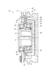
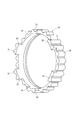
- FIG. 1 is a view showing a valve timing adjusting device according to a first embodiment, and is a cross-sectional view taken along the line II of FIG. 2 is a sectional view taken along line II-II of FIG. 3 is a sectional view taken along the line III-III of FIG. 4 is a sectional view taken along line IV-IV of FIG. 5 is a perspective view of the planetary rotator of FIG.
- FIG. 6 is an enlarged view of the VI portion of FIG.
- FIG. 7 is an enlarged view of the VII portion of FIG. FIG.
- FIG. 8 is a cross-sectional view showing the valve timing adjusting device according to the second embodiment and is a view corresponding to FIG. 4.
- FIG. 9 is a cross-sectional view showing the valve timing adjusting device according to the third embodiment and is a view corresponding to FIG. 4.
- FIG. 10 is a cross-sectional view showing the valve timing adjusting device according to the fourth embodiment and is a view corresponding to FIG. 4.
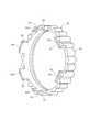
- 11 is a perspective view of the planetary rotator of FIG. 12 is a view of the planetary rotator and the specific receiving surface of FIG. 10 when viewed from the specific receiving surface side
- FIG. 13 is a cross-sectional view showing the valve timing adjusting device according to the fifth embodiment and is a view corresponding to FIG. 4.
- FIG. 14 is a cross-sectional view showing a valve timing adjusting device according to a sixth embodiment and is a view corresponding to FIG.
- FIG. 15 is a cross-sectional view showing the valve timing adjusting device according to the seventh embodiment and is a view corresponding to FIG. 4.
- FIG. 16 is a cross-sectional view showing the valve timing adjusting device according to the eighth embodiment and is a view corresponding to FIG. 4.
- FIG. 17 is a side view of the planetary rotator of FIG.
- FIG. 18 is a cross-sectional view showing the valve timing adjusting device according to the ninth embodiment and is a view corresponding to FIG.
- FIG. 19 is a sectional view showing the valve timing adjusting device according to the tenth embodiment and is a view corresponding to FIG. 4.
- FIG. 20 is a cross-sectional view showing the valve timing adjusting device according to the eleventh embodiment and is a view corresponding to FIG. 4.
- valve timing adjusting device A plurality of embodiments of the valve timing adjusting device will be described below with reference to the drawings.
- the configurations that are substantially the same between the embodiments are given the same reference numerals, and description thereof will be omitted. Further, not only the combination of the configurations explicitly described in the description of each embodiment but also the configuration of each embodiment can be partially combined even if not explicitly stated, unless there is a problem in the combination.
- the valve timing adjusting device 10 As shown in FIG. 1, the valve timing adjusting device 10 according to the first embodiment is attached to a torque transmission path from a crankshaft 5 to a camshaft 6 in an internal combustion engine of a vehicle.
- the cam shaft 6 opens and closes an intake valve or an exhaust valve (not shown) as a valve.
- the valve timing adjusting device 10 adjusts the valve timing of the valve.
- the valve timing adjustment device 10 includes an actuator 11, a control unit 12, and a phase conversion unit 13.
- the actuator 11 is an electric motor such as a brushless motor, and has a housing 21 and a control shaft 22.
- the housing 21 rotatably supports the control shaft 22.
- the control unit 12 is composed of, for example, a drive driver and a microcomputer, and controls the energization of the actuator 11 to rotationally drive the control shaft 22.
- the phase conversion unit 13 includes a driving side rotating body 23, a driven side rotating body 24, an eccentric shaft 25, a planetary rotating body 26, and a transmission mechanism 27.
- the drive-side rotating body 23 is formed by fastening a bottomed tubular sprocket member 31 and a stepped tubular cover member 32, and is arranged coaxially with the camshaft 6.
- the drive side rotating body 23 accommodates the other constituent members 24, 25, 26 and 27.
- the sprocket member 31 is connected to the crankshaft 5 via a transmission member 7 such as a chain. As a result, the drive-side rotating body 23 rotates around the rotation center line O coaxial with the cam shaft 6 in conjunction with the crank shaft 5.
- the driven-side rotating body 24 is formed in a cylindrical shape with a bottom, and the bottom is fixed to the end of the camshaft 6.
- the driven-side rotating body 24 is arranged coaxially with the cam shaft 6 and radially supports the sprocket member 31 from the radially inner side.
- the driven-side rotary body 24 is rotatable relative to the drive-side rotary body 23 while rotating integrally with the cam shaft 6 around the rotation center line O.
- the internal gear 28 is integrally formed inside the cylindrical portion of the driven-side rotating body 24.
- the internal gear portion 28 is a gear portion having a tip circle inside the root circle in the radial direction.
- the eccentric shaft 25 is formed in a tubular shape, and is arranged coaxially with the cam shaft 6.
- the eccentric shaft 25 is rotatably supported around a rotation center line O by a radial bearing 33 provided inside the cover member 32.
- An eccentric portion 34 that is eccentric with respect to the rotation center line O is formed in a portion of the eccentric shaft 25 that overlaps the internal gear portion 28 in the axial direction.
- the planetary rotating body 26 has a planetary gear portion 35 that is eccentric with respect to the rotation center line O and meshes with the internal gear portion 28.
- the planetary gear unit 35 is a gear unit having a tip circle on the outer side in the radial direction of the root circle.
- the planetary rotator 26 is supported by a radial bearing 36 provided outside the eccentric portion 34 so as to be rotatable about the rotation center line C.
- the planetary gear unit 35 integrally moves while changing the meshing portion with the internal gear unit 28 according to the relative rotation of the eccentric shaft 25 with respect to the drive-side rotating body 23.
- the planetary rotating body 26 revolves around the rotation axis O while rotating around the rotation center line C while meshing with the driven side rotation body 24 on the eccentric side.
- An elastic member 37 is provided between the radial bearing 36 and the eccentric side of the eccentric portion 34.
- the elastic member 37 biases the planetary rotor 26 toward the radial eccentric side via the radial bearing 36.
- the planetary gear unit 35 maintains the meshed state with the internal gear unit 28.
- the transmission mechanism 27 absorbs the eccentricity between the drive-side rotating body 23 and the planetary rotating body 26 while transmitting rotation between them.
- the transmission mechanism 27 includes a first engagement groove 41 formed in the sprocket member 31, a second engagement protrusion 42 formed in the planetary rotator 26, a first engagement groove 41 and a second engagement groove 41.
- An Oldham mechanism that includes a slider 43 that swings in a radial direction with respect to the engagement protrusion 42 and transmits rotation between them.
- the slider 43 is formed on a ring portion 44, a first engagement protrusion 45 that protrudes radially outward from the ring portion 44 and is fitted in the first engagement groove 41, and a radial inner side of the ring portion 44.
- the second engaging groove 46 fitted to the second engaging protrusion 42.
- the rotational phase of the driven-side rotating body 24 with respect to the driving-side rotating body 23 (hereinafter, simply “rotational phase”) is set to a predetermined phase according to the rotating state of the control shaft 22. Adjust within the adjustment range. As a result, the valve timing adjustment suitable for the operating condition of the internal combustion engine is realized.
- control shaft 22 rotates at the same speed as the drive-side rotating body 23, and when the eccentric shaft 25 does not rotate relative to the drive-side rotating body 23, the planetary rotating body 26 does not make a planetary motion.
- the rotating bodies 23 and 24 rotate together with the planetary rotating body 26 and the rotation phase becomes substantially unchanged, so that the valve timing is held and adjusted.
- the planetary rotating body 26 has a planetary motion. To do.
- the driven-side rotary body 24 relatively rotates in the retard direction with respect to the drive-side rotary body 23, and the rotational phase changes in the retard angle, whereby the valve timing is retarded.
- the eccentric shaft 25 relatively rotates in the advance direction with respect to the drive-side rotating body 23 by the control shaft 22 rotating at a higher speed than the drive-side rotating body 23, the planetary rotating body 26 makes a planetary motion.
- the driven-side rotating body 24 relatively rotates in the advancing direction with respect to the driving-side rotating body 23 and the rotational phase changes in the advancing angle, so that the valve timing is advanced.
- the phase adjustment range in which the rotation phase is adjusted is defined by the stoppers 47 of the driven-side rotating body 24 being locked by the drive-side rotating body 23 on both sides in the rotation direction.
- the valve timing adjustment device 10 When the direction of the torque input to the planetary gear mechanism is periodically switched as in the valve timing adjustment device 10, striking noise and knocking wear due to collisions between structural parts pose problems. Such a collision occurs not only on the torque transmission surface of the gear and the Oldham mechanism but also on the thrust bearing portion (that is, the axial regulation portion).
- the valve timing adjustment device 10 has a configuration for suppressing collision of the planetary rotor 26 in the thrust direction.
- the planetary rotating body 26 has a planetary thrust bearing portion 51 that is a bearing portion in the thrust direction.
- the drive-side rotating body 23 as a specific rotating body that comes into contact with the planetary thrust bearing portion 51 in the thrust direction has a specific thrust bearing portion 52 that is a bearing portion in the thrust direction.
- the planetary thrust bearing portion 51 and the specific thrust bearing portion 52 form a thrust bearing between the planetary rotor 26 and the drive side rotor 23.
- the planetary thrust bearing portion 51 is composed of the tips of a plurality of protrusions 53 that project in the axial direction toward the drive-side rotating body 23.
- the protrusions 53 are provided on a circle concentric with the rotation center line C, and six protrusions 53 are provided at equal intervals around the rotation center line C. Two of the six protrusions 53 are the first engagement protrusions 45.
- the specific thrust bearing portion 52 is an end portion of the inner peripheral portion of the driving side rotating body 23 on the planetary rotating body 26 side, and is coaxial with the rotation center line O. It is composed of an annular portion.
- the specific thrust bearing portion 52 has an annular specific receiving surface 54 that can come into contact with the planetary thrust bearing portion 51.
- the specific receiving surface 54 is separated from the planetary thrust bearing portion 51 radially outward.
- the eccentric side of the planetary thrust bearing portion 51 is in contact with the specific receiving surface 54 radially inward of the specific receiving surface 54, and the anti-eccentric side opposite to the eccentric side approaches the drive side rotating body 23 side.
- the planetary rotator 26 tilts, there is a space for allowing the opposite eccentric side to escape.
- the specific thrust bearing portion 52 and the planet thrust bearing portion 51 contact only the eccentric side of the planetary rotor 26 in the parallel state.
- the specific thrust bearing portion 52 and the planetary thrust bearing portion 51 contact only the eccentric side of the planetary rotor 26 in the parallel state. In this way, the specific thrust bearing portion 52 and the planetary thrust bearing portion 51 are brought into contact with each other on the eccentric side and are separated from each other on the anti-eccentric side, so that the tiltability of the planetary rotary body 26 and the axial positioning ability are compatible.
- the projection size of the planetary rotator 26 in the axial direction increases, and the clearance in the thrust direction between the planetary rotator 26 and the drive side rotator 23 decreases.
- the inclination angles of the planetary rotating body 26 with respect to the drive-side rotating body 23 change and they come into contact with each other, so that the impact is mitigated. Therefore, noise and impact force due to the thrust-direction collision between the planetary rotary body 26 and the drive-side rotary body 23 can be reduced, and quietness and durability are improved.
- the force that tilts the planetary rotor 26 is a radial component force due to the transmission torque of the meshing portion between the planetary gear unit 35 and the internal gear unit 28, so the tilting direction of the planetary rotor 26 is the eccentric direction.
- the direction is perpendicular to.
- the specific thrust bearing portion 52 and the planetary thrust bearing portion 51 are configured to be in contact with each other on the eccentric side while being separated from each other on the anti-eccentric side, so that the range in which the planetary rotor 26 is inclined increases. It becomes a quieter configuration.
- noise and impact force can be reduced without adding any parts in the first embodiment. ..
- the planet thrust bearing portion 512 is composed of an end portion of the planetary rotor 26 on the driven side rotor 24 side.
- the specific thrust bearing portion 522 is formed of an annular portion coaxial with the rotation center line O at a position facing the planetary thrust bearing portion 512 in the driven side rotating body 24.
- the specific thrust bearing portion 522 and the planetary thrust bearing portion 512 contact only the eccentric side of the planetary rotor 26 in the parallel state.
- the thrust bearing may be provided between the planetary rotor 26 and the driven rotor 24. Nevertheless, by bringing the specific thrust bearing portion 522 and the planetary thrust bearing portion 512 into contact with each other on the eccentric side and separating them from the anti-eccentric side, the same effect as in the first embodiment can be obtained.
- the radial bearing 33 is provided inside the tubular portion of the driven side rotating body 24.
- the eccentric shaft 25 is likely to tilt.
- the planetary rotor 26 is tilted and the clearance in the thrust direction is reduced, so that noise and impact force can be effectively reduced.
- the planet thrust bearing portion 514 has a smaller outer diameter than the planet thrust bearing portion 51 in the first embodiment. That is, the concave portion 61 is formed radially outward of the projection 53 with respect to the planetary thrust bearing portion 514.
- the outer diameter B of the planetary thrust bearing portion 514 is smaller than the inner diameter A of the specific thrust bearing portion 52.
- the anti-eccentric side of the specific receiving surface 54 is separated from the planet thrust bearing portion 514 in the radial direction, and the half of the specific receiving surface 54 on the anti-eccentric side does not contact the planet thrust bearing portion 514. ..
- the specific thrust bearing portion 52 and the planetary thrust bearing portion 51 are reliably separated from each other on the anti-eccentric side, and the planetary rotor 26 is easily tilted, so that noise and impact force can be effectively reduced. ..
- the specific thrust bearing portion 52 has a tapered specific receiving surface 545 formed on the inner peripheral portion so as to be spaced apart from the planetary thrust bearing portion 51 inward in the radial direction.
- the specific thrust bearing portion 52 and the planetary thrust bearing portion 51 are separated from each other on the side opposite to the eccentric side, and the planetary rotor 26 is easily tilted, so that noise and impact force can be effectively reduced.
- the specific thrust bearing portion 52 has a curved specific receiving surface 546 formed on the inner peripheral portion so as to be spaced from the planetary thrust bearing portion 51 inward in the radial direction.
- the specific thrust bearing portion 52 and the planetary thrust bearing portion 51 are separated from each other on the side opposite to the eccentric side, and the planetary rotor 26 is easily tilted, so that noise and impact force can be effectively reduced.
- the planetary thrust bearing portion 51 has a tapered surface 63 formed on the outer peripheral portion so as to be spaced apart from the specific thrust bearing portion 52 toward the radially outer side.
- the specific thrust bearing portion 52 and the planetary thrust bearing portion 51 are separated from each other on the side opposite to the eccentric side, and the planetary rotor 26 is easily tilted, so that noise and impact force can be effectively reduced.
- the specific thrust bearing portion 528 is composed of an annular portion that is coaxial with the rotation center line O, and the outer peripheral side is closer to the planetary rotor 26 than the inner peripheral side. It has a recess 65 formed to be recessed. The specific thrust bearing portion 528 contacts the planetary thrust bearing portion 51 only on the side opposite to the eccentric side in the parallel state.
- the specific thrust bearing portion 528 and the planetary thrust bearing portion 51 may be in contact with each other on the anti-eccentric side while being separated from each other on the eccentric side. Still, the planetary rotor 26 is tilted to reduce the clearance in the thrust direction, and the same effect as that of the first embodiment can be obtained.
- the planetary thrust bearing portion 519 is composed of the tip end portion of the protrusion 53 located on the eccentric side when the rotation phase is the specific phase.
- the projection 67 located on the opposite eccentric side has a shorter axial length than the projection 53 located on the eccentric side. That is, an axial step is provided between the protrusion 67 and the protrusion 53.
- the specific thrust bearing portion 52 and the planetary thrust bearing portion 519 contact only on the eccentric side when the rotation phase is the specific phase.
- the above specific phase is the rotational phase during idle rotation, where noise is a particular issue. This makes it possible to reduce the clearance in the thrust direction by tilting the planetary rotor 26 during idle rotation where noise is a particular problem, and to reduce noise and impact force.
- control unit 12 controls so that the rotation phase is not held at the specific phase when the engine speed is high at 3000 rpm or higher. As a result, it is possible to prevent the inclination of the planetary gear unit 35 from becoming excessive at the time of high rotation and promoting wear.
- a biasing portion 69 that biases the planetary rotor 26 toward the specific thrust bearing portion 52 is provided.
- the urging portion 69 is composed of a flat spring, but it may be composed of an elastic body or hydraulic pressure generating means.
- the radial bearing 71 provided between the eccentric portion 34 and the planetary rotor 26 is an angular ball bearing.
- the axial component force generated in the radial bearing 71 by the urging of the elastic member 37 as the urging portion urges the planetary rotor 26 toward the specific thrust bearing portion 52.
- the planetary thrust bearing portion 519 is provided in a part of the rotational direction, so that the specific thrust bearing portion 52 and the planetary thrust bearing portion 519 come into contact with each other only on the eccentric side in the specific phase. ..
- the concave portion is provided in a part of the specific thrust bearing portion in the rotation direction, so that the specific thrust bearing portion and the planetary thrust bearing portion are in contact with each other only on the eccentric side in the specific phase. May be.
- the internal gear unit may be formed on the driving side rotating body.
- the transmission mechanism may be provided so as to transmit rotation between the driven side rotating body and the planetary rotating body.
Landscapes
- Engineering & Computer Science (AREA)
- Mechanical Engineering (AREA)
- General Engineering & Computer Science (AREA)
- Valve Device For Special Equipments (AREA)
Abstract
Un dispositif de réglage de calage de distribution (10) comprend une partie d'engrenage interne (28) formée sur un corps rotatif choisi parmi un corps rotatif côté entraîné (24) et un corps rotatif côté entraînement (23), un corps rotatif planétaire (26) ayant une partie d'engrenage planétaire (35) qui s'engrène avec la partie d'engrenage interne (28), un arbre excentrique (25) qui supporte le corps rotatif planétaire (26), et un mécanisme de transmission (27) qui transmet une rotation entre le corps rotatif planétaire (26) et l'autre des corps rotatifs susmentionnés. Lorsqu'une partie de palier de butée planétaire (51) est une partie de palier du corps rotatif planétaire (26) dans la direction de poussée, un corps rotatif spécifique est un quelconque élément choisi parmi le corps rotatif côté entraînement (23) et le corps rotatif côté entraîné (24) et est en contact avec la partie de palier de butée planétaire (51) dans la direction de poussée, et une partie de palier de butée spécifique (52) est une partie de palier du corps rotatif spécifique dans la direction de poussée, la partie de palier de butée spécifique (52) et la partie de palier de butée planétaire (51) sont en contact, dans un état parallèle, uniquement sur le côté excentrique ou le côté excentrique opposé, qui est opposé au côté excentrique, du corps rotatif planétaire (26).
Priority Applications (2)
| Application Number | Priority Date | Filing Date | Title |
|---|---|---|---|
| CN201980079589.XA CN113167140B (zh) | 2018-12-28 | 2019-12-19 | 阀正时调整装置 |
| US17/338,350 US11339689B2 (en) | 2018-12-28 | 2021-06-03 | Valve timing adjustment device |
Applications Claiming Priority (2)
| Application Number | Priority Date | Filing Date | Title |
|---|---|---|---|
| JP2018247625A JP7056931B2 (ja) | 2018-12-28 | 2018-12-28 | バルブタイミング調整装置 |
| JP2018-247625 | 2018-12-28 |
Related Child Applications (1)
| Application Number | Title | Priority Date | Filing Date |
|---|---|---|---|
| US17/338,350 Continuation US11339689B2 (en) | 2018-12-28 | 2021-06-03 | Valve timing adjustment device |
Publications (1)
| Publication Number | Publication Date |
|---|---|
| WO2020137782A1 true WO2020137782A1 (fr) | 2020-07-02 |
Family
ID=71128628
Family Applications (1)
| Application Number | Title | Priority Date | Filing Date |
|---|---|---|---|
| PCT/JP2019/049779 Ceased WO2020137782A1 (fr) | 2018-12-28 | 2019-12-19 | Dispositif de réglage de calage de distribution |
Country Status (4)
| Country | Link |
|---|---|
| US (1) | US11339689B2 (fr) |
| JP (1) | JP7056931B2 (fr) |
| CN (1) | CN113167140B (fr) |
| WO (1) | WO2020137782A1 (fr) |
Cited By (1)
| Publication number | Priority date | Publication date | Assignee | Title |
|---|---|---|---|---|
| JP2022030986A (ja) * | 2020-08-07 | 2022-02-18 | 株式会社デンソー | バルブタイミング調整装置 |
Citations (3)
| Publication number | Priority date | Publication date | Assignee | Title |
|---|---|---|---|---|
| JP2008095551A (ja) * | 2006-10-06 | 2008-04-24 | Denso Corp | バルブタイミング調整装置 |
| JP2015001190A (ja) * | 2013-06-14 | 2015-01-05 | 株式会社デンソー | バルブタイミング調整装置 |
| JP2015140749A (ja) * | 2014-01-29 | 2015-08-03 | 株式会社日本自動車部品総合研究所 | バルブタイミング調整装置 |
Family Cites Families (5)
| Publication number | Priority date | Publication date | Assignee | Title |
|---|---|---|---|---|
| JP2016044627A (ja) * | 2014-08-25 | 2016-04-04 | アイシン精機株式会社 | 弁開閉時期制御装置 |
| CN106605044B (zh) * | 2014-09-04 | 2018-02-23 | 博格华纳公司 | 具有行星齿轮组的发动机可变凸轮轴正时相位器 |
| JP6308176B2 (ja) * | 2015-06-23 | 2018-04-11 | 株式会社Soken | バルブタイミング調整装置 |
| JP6790640B2 (ja) * | 2016-09-15 | 2020-11-25 | アイシン精機株式会社 | 弁開閉時期制御装置 |
| JP6838506B2 (ja) | 2016-11-18 | 2021-03-03 | アイシン精機株式会社 | 弁開閉時期制御装置 |
-
2018
- 2018-12-28 JP JP2018247625A patent/JP7056931B2/ja not_active Expired - Fee Related
-
2019
- 2019-12-19 CN CN201980079589.XA patent/CN113167140B/zh not_active Expired - Fee Related
- 2019-12-19 WO PCT/JP2019/049779 patent/WO2020137782A1/fr not_active Ceased
-
2021
- 2021-06-03 US US17/338,350 patent/US11339689B2/en active Active
Patent Citations (3)
| Publication number | Priority date | Publication date | Assignee | Title |
|---|---|---|---|---|
| JP2008095551A (ja) * | 2006-10-06 | 2008-04-24 | Denso Corp | バルブタイミング調整装置 |
| JP2015001190A (ja) * | 2013-06-14 | 2015-01-05 | 株式会社デンソー | バルブタイミング調整装置 |
| JP2015140749A (ja) * | 2014-01-29 | 2015-08-03 | 株式会社日本自動車部品総合研究所 | バルブタイミング調整装置 |
Cited By (2)
| Publication number | Priority date | Publication date | Assignee | Title |
|---|---|---|---|---|
| JP2022030986A (ja) * | 2020-08-07 | 2022-02-18 | 株式会社デンソー | バルブタイミング調整装置 |
| JP7424245B2 (ja) | 2020-08-07 | 2024-01-30 | 株式会社デンソー | バルブタイミング調整装置 |
Also Published As
| Publication number | Publication date |
|---|---|
| JP2020106008A (ja) | 2020-07-09 |
| CN113167140A (zh) | 2021-07-23 |
| CN113167140B (zh) | 2023-01-10 |
| US20210285344A1 (en) | 2021-09-16 |
| US11339689B2 (en) | 2022-05-24 |
| JP7056931B2 (ja) | 2022-04-19 |
Similar Documents
| Publication | Publication Date | Title |
|---|---|---|
| JP3494439B2 (ja) | 可変動弁機構 | |
| JP5987868B2 (ja) | バルブタイミング調整装置 | |
| KR101896672B1 (ko) | 밸브 타이밍 조정장치 | |
| JP6102846B2 (ja) | バルブタイミング調整装置 | |
| JP2007224865A (ja) | バルブタイミング調整装置 | |
| JP6443382B2 (ja) | バルブタイミング調整装置 | |
| JP4760953B2 (ja) | バルブタイミング調整装置 | |
| JP2009215954A (ja) | バルブタイミング調整装置 | |
| WO2020137782A1 (fr) | Dispositif de réglage de calage de distribution | |
| US11459916B2 (en) | Valve timing adjustment device | |
| JP7368152B2 (ja) | バルブタイミング調整装置 | |
| US11441453B2 (en) | Valve timing adjustment device | |
| JP6740968B2 (ja) | バルブタイミング調整装置 | |
| JP7294745B2 (ja) | バルブタイミング調整装置 | |
| JP7131445B2 (ja) | バルブタイミング調整装置 | |
| JP2009074398A (ja) | バルブタイミング調整装置 | |
| JP5920096B2 (ja) | バルブタイミング調整装置 | |
| JP2024119301A (ja) | バルブタイミング調整装置 | |
| JP2017172656A (ja) | 遊星歯車装置 |
Legal Events
| Date | Code | Title | Description |
|---|---|---|---|
| 121 | Ep: the epo has been informed by wipo that ep was designated in this application |
Ref document number: 19906310 Country of ref document: EP Kind code of ref document: A1 |
|
| NENP | Non-entry into the national phase |
Ref country code: DE |
|
| 122 | Ep: pct application non-entry in european phase |
Ref document number: 19906310 Country of ref document: EP Kind code of ref document: A1 |