WO2020138136A1 - Dispositif de traitement d'image, procédé de traitement d'images et programme - Google Patents
Dispositif de traitement d'image, procédé de traitement d'images et programme Download PDFInfo
- Publication number
- WO2020138136A1 WO2020138136A1 PCT/JP2019/050752 JP2019050752W WO2020138136A1 WO 2020138136 A1 WO2020138136 A1 WO 2020138136A1 JP 2019050752 W JP2019050752 W JP 2019050752W WO 2020138136 A1 WO2020138136 A1 WO 2020138136A1
- Authority
- WO
- WIPO (PCT)
- Prior art keywords
- image
- phase
- moving image
- combined
- moving
- Prior art date
- Legal status (The legal status is an assumption and is not a legal conclusion. Google has not performed a legal analysis and makes no representation as to the accuracy of the status listed.)
- Ceased
Links
Images




Classifications
-
- G—PHYSICS
- G06—COMPUTING OR CALCULATING; COUNTING
- G06T—IMAGE DATA PROCESSING OR GENERATION, IN GENERAL
- G06T7/00—Image analysis
- G06T7/0002—Inspection of images, e.g. flaw detection
- G06T7/0012—Biomedical image inspection
- G06T7/0014—Biomedical image inspection using an image reference approach
- G06T7/0016—Biomedical image inspection using an image reference approach involving temporal comparison
-
- A—HUMAN NECESSITIES
- A61—MEDICAL OR VETERINARY SCIENCE; HYGIENE
- A61B—DIAGNOSIS; SURGERY; IDENTIFICATION
- A61B6/00—Apparatus or devices for radiation diagnosis; Apparatus or devices for radiation diagnosis combined with radiation therapy equipment
- A61B6/02—Arrangements for diagnosis sequentially in different planes; Stereoscopic radiation diagnosis
- A61B6/03—Computed tomography [CT]
-
- G—PHYSICS
- G06—COMPUTING OR CALCULATING; COUNTING
- G06T—IMAGE DATA PROCESSING OR GENERATION, IN GENERAL
- G06T7/00—Image analysis
- G06T7/20—Analysis of motion
- G06T7/246—Analysis of motion using feature-based methods, e.g. the tracking of corners or segments
- G06T7/248—Analysis of motion using feature-based methods, e.g. the tracking of corners or segments involving reference images or patches
-
- G—PHYSICS
- G06—COMPUTING OR CALCULATING; COUNTING
- G06T—IMAGE DATA PROCESSING OR GENERATION, IN GENERAL
- G06T7/00—Image analysis
- G06T7/70—Determining position or orientation of objects or cameras
- G06T7/73—Determining position or orientation of objects or cameras using feature-based methods
- G06T7/74—Determining position or orientation of objects or cameras using feature-based methods involving reference images or patches
-
- G—PHYSICS
- G06—COMPUTING OR CALCULATING; COUNTING
- G06T—IMAGE DATA PROCESSING OR GENERATION, IN GENERAL
- G06T2207/00—Indexing scheme for image analysis or image enhancement
- G06T2207/10—Image acquisition modality
- G06T2207/10016—Video; Image sequence
-
- G—PHYSICS
- G06—COMPUTING OR CALCULATING; COUNTING
- G06T—IMAGE DATA PROCESSING OR GENERATION, IN GENERAL
- G06T2207/00—Indexing scheme for image analysis or image enhancement
- G06T2207/10—Image acquisition modality
- G06T2207/10072—Tomographic images
- G06T2207/10076—4D tomography; Time-sequential 3D tomography
-
- G—PHYSICS
- G06—COMPUTING OR CALCULATING; COUNTING
- G06T—IMAGE DATA PROCESSING OR GENERATION, IN GENERAL
- G06T2207/00—Indexing scheme for image analysis or image enhancement
- G06T2207/20—Special algorithmic details
- G06T2207/20212—Image combination
- G06T2207/20221—Image fusion; Image merging
-
- G—PHYSICS
- G06—COMPUTING OR CALCULATING; COUNTING
- G06T—IMAGE DATA PROCESSING OR GENERATION, IN GENERAL
- G06T2207/00—Indexing scheme for image analysis or image enhancement
- G06T2207/30—Subject of image; Context of image processing
- G06T2207/30004—Biomedical image processing
- G06T2207/30061—Lung
Definitions
- the disclosure of the present specification relates to an image processing device, an image processing method, and a program.
- doctors make diagnoses using medical images obtained by imaging the site of the subject to be observed with various modalities.
- a plurality of medical images with different time phases may be used.
- Patent Document 1 As a technique relating to a diagnosis performed using a plurality of medical images having different time phases, there is known a technique of calculating a slip degree from two images obtained by imaging a chest region of the same patient in two time phases having different inspiration volumes. (Patent Document 1).
- Patent Document 1 the degree of slippage is calculated when the region of the observation target region included in the imaging range differs between the plurality of medical images having different time phases due to the movement of the observation target region. There was a problem that was difficult.
- the disclosure of the present specification is an image in which the degree of slippage can be accurately calculated even when the regions of the site to be observed included in the imaging range are different between a plurality of medical images having different time phases.
- One of the purposes is to provide a processing device.
- the present invention is not limited to the above-described object, and it is also possible to obtain operational effects that are obtained by the respective configurations shown in the modes for carrying out the invention described below, and that are not obtained by conventional techniques. It can be positioned as one of the other purposes.
- An image processing device disclosed in the present specification includes a moving image acquisition unit that acquires a first moving image and a second moving image obtained by capturing an image of an object from different positions with an image capturing device, and the first image capturing device.
- a moving image acquisition unit that acquires a first moving image and a second moving image obtained by capturing an image of an object from different positions with an image capturing device, and the first image capturing device.
- a slip degree calculating means for calculating the slip degree of the object based on the deformation information estimated from the combined image.
- FIG. 3 is a diagram showing an example of a device configuration of the image processing apparatus according to the first embodiment.
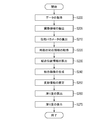
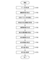
- the flowchart which shows an example of the whole process procedure in 1st Embodiment.
- the figure which shows an example of matching of the 1st moving image and 2nd moving image in 1st Embodiment.
- the image processing apparatus uses three-dimensional moving images (first moving image and second moving image) obtained by dividing an area of an organ, which is an observation target, which moves periodically, and capturing the divided area. Then, it is a device for calculating the slip degree in the vicinity of the contour of the entire region of the organ to be observed.
- the degree of slippage is movement information indicating how much a certain area in the image slides with respect to the surrounding area. That is, it is the amount of movement relative to the surroundings of the target. For example, the lungs move with respiratory movements such that the surface of the lung (also called the visceral pleura) slides around it (also called the parietal pleura).
- the image processing apparatus displays the surface position of the lung and the slip degree at the surface position in association with each other.
- the slippage is displayed smaller at the surface position where the adhesion exists than in the non-adhesive part.
- the image processing apparatus acquires a first moving image and a second moving image obtained by photographing an observation target (object) from different positions with an imaging device. Specifically, the first moving image and the second moving image captured by dividing the region are acquired so that at least some of the regions to be observed overlap. Then, by analyzing the first moving image, the phase information of the movement of the organ in each time-phase image of the first moving image (still image at each time (each time phase) configuring the first moving image) To obtain a first phase parameter representing Similarly, by analyzing the second moving image, the phase of the movement of the organ in each time-phase image of the second moving image (still image at each time (each time phase) configuring the second moving image) Obtain a second phase parameter that represents the information.
- the time phase images in which the phase information of the motion of the organ is similar between the first moving image and the second moving image are associated with each other.
- a combined image in the relevant phase is generated.
- a three-dimensional moving image obtained by capturing the respiratory motion of the lung with the X-ray CT apparatus will be described as an example.
- the implementation of the image processing device disclosed in the present specification is not limited to this, and a moving image obtained by capturing an arbitrary portion such as a heart that performs a spontaneous movement may be used. Further, it may be a moving image obtained by photographing an arbitrary site where the subject makes a periodic movement (for example, bending and stretching movement).
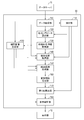
- FIG. 1 shows the configuration of the image processing apparatus according to this embodiment.
- the image processing apparatus 10 according to the present embodiment is connected to the data server 11 and the display unit 12.
- the data server 11 holds the first moving image and the second moving image designated by the user as the target for calculating the slippage.
- the first moving image and the second moving image are moving images (three-dimensional moving images) composed of three-dimensional tomographic images of a plurality of time phases, which are obtained by previously capturing different imaging ranges of the same subject with the same modality. It is also called an image or a four-dimensional image).
- the modality that captures a three-dimensional tomographic image may be an MRI apparatus, an X-ray CT apparatus, a three-dimensional ultrasonic imaging apparatus, a photoacoustic tomography apparatus, a PET/SPECT, an OCT apparatus, or the like.
- the first moving image and the second moving image are input to the image processing device 10 via the data acquisition unit 110.
- the display unit 12 is a monitor that displays an image generated by the image processing apparatus 10.
- the image processing device 10 is composed of the following components.
- the data acquisition unit 110 acquires the first moving image and the second moving image input to the image processing apparatus 10.
- the extraction unit 115 extracts the region of the target organ in each time phase of the first moving image and the second moving image.
- the phase parameter calculation unit 120 represents the first phase parameter indicating the phase information of the motion of the organ in each time phase of the first moving image and the phase information of the motion of the organ in each time phase of the second moving image. Get the second phase parameter.
- the time phase correspondence information acquisition unit 130 acquires the correspondence information of each time phase of the first moving image and the second moving image based on the first phase parameter and the second phase parameter.
- the time phase image of the second moving image (second time phase image) is associated with each time phase image of the first moving image (first time phase image).
- the combined position acquisition unit 140 acquires the combined position between the first time phase image and the second time phase image associated with each other as the same phase.
- the combined image generation unit 150 generates a combined image in which the first time phase image and the second time phase image are combined based on the combination position.
- the deformation information estimation unit 160 acquires deformation information between a plurality of time phases with respect to a combined image generated in a plurality of time phases.
- the slippage calculator 170 calculates the slippage near the contour in the entire region of the organ to be observed, based on the deformation information.
- the display control unit 180 performs display control for displaying the first moving image, the second moving image, and the slippage on the display unit 12.
- Each component of the image processing device 10 described above functions according to a computer program.
- the function of each component is realized by the CPU reading and executing a computer program stored in the ROM or the storage unit using the RAM as a work area.
- some or all of the functions of the components of the image processing apparatus 10 may be realized by using a dedicated circuit.
- some functions of the constituent elements of the CPU may be realized by using a cloud computer.
- an arithmetic device in a location different from the image processing device 10 is communicatively connected to the image processing device 10 via a network, and the image processing device 10 and the arithmetic device transmit and receive data, thereby the image processing device 10
- the functions of the components of the control unit may be realized.
- FIG. 2 shows a flowchart of the overall processing procedure performed by the image processing apparatus 10.
- step S200 the data acquisition unit 110 acquires a first moving image and a second moving image obtained by capturing images of an object from different positions by the image capturing device input to the image processing device 10. That is, step S200 corresponds to an example of a moving image acquisition step of acquiring the first moving image and the second moving image obtained by shooting the object from different positions with the imaging device.
- the first moving image and the second moving image captured by dividing the lung in the cranio-caudal direction so that at least some regions of the lung overlap.
- the first moving image includes the lung apex
- the second moving image includes the lung bottom.
- the observation target is not limited to the lung, and may be, for example, a heart in which the presence or absence of a disease appears in the movement of the organ, as in the lung, or other organs.
- the acquired first moving image and second acquired moving image are output to the extraction unit 115, the phase parameter calculation unit 120, and the combined position acquisition unit 140.
- step S205 extraction of organ area
- the extraction unit 115 extracts the region of the target organ in each time phase of the first moving image and the second moving image. Then, the information on the extracted region of the target organ is output to the phase parameter calculation unit 120, the coupling position acquisition unit 140, and the slippage calculation unit 170.
- a known image processing method can be used for the extraction processing of the region of the organ from the image. Any threshold value processing using a pixel value threshold value may be used, or known segmentation processing such as graph cut processing may be used.
- the user may manually extract the region of the target organ by using a graphic drawing software (not shown), or the region of the target organ extracted by a known image processing method may be manually corrected by the user. But it's okay.
- step S210 the phase parameter calculation unit 120 calculates the first phase parameter representing the phase information of the periodic motion of the target organ by analyzing the first moving image. In addition, by analyzing the second moving image, a second phase parameter representing the phase information of the periodic motion of the target organ is calculated.
- the periodic motion of the target organ is, for example, respiratory motion of the lungs or pulsation of the heart.
- the phase parameter calculation unit 120 calculates the first phase parameter indicating the phase information of the movement of the target object in each time phase of the first moving image and the movement of the target object in each time phase of the second moving image. It corresponds to an example of a phase acquisition unit that acquires the second phase parameter in each time phase of the second moving image indicating the phase information.
- the phase parameter calculation unit 120 acquires the first phase parameter based on the aspect of the target object captured in the first moving image and determines the state of the target object captured in the second moving image. Based on that, the second phase parameter is acquired.
- the calculated first phase parameter and the calculated second phase parameter are output to the time phase correspondence information acquisition unit 130.
- the phase parameter calculation unit 120 uses, as the first phase parameter, a numerical value that correlates with the periodic motion of the target organ from each time phase image (still image of each time phase) included in the first moving image. To calculate.
- the target organ is the lung
- the volume of the lung changes in conjunction with the respiratory motion, so the lung region extracted in step S205 is used to measure the volume of the lung included in each time-phase image
- the size of the lung volume in the temporal image is used as the first phase parameter.
- the size of the lung area within a predetermined slice plane may be used as the first phase parameter.
- the pixel value of the air region in the lung region changes according to the lung volume.
- the first phase parameter may be calculated based on the distribution information of the pixel values in the lung region included in each time phase image. It should be noted that not only the information that can be acquired from the lungs, but also the information on the peripheral region that is linked with the respiratory movement may be used. For example, the first phase parameter may be calculated based on the body surface of the chest and abdomen or the movement of other organs. Further, the first phase parameter may be calculated by integrating a plurality of pieces of information linked with respiratory movements.
- the second phase parameter is also acquired by analyzing the second moving image using various methods as with the first phase parameter.
- the first phase parameter and the second phase parameter do not necessarily have to be calculated by the same method.
- the configuration may be such that the phase parameter can be acquired from an external device (not shown).
- the ventilation volume of the subject may be measured using a spirometer at the same time when the moving image is captured, and the measured value may be used as the phase parameter.
- the movement of the body surface of the subject at the time of capturing the moving image may be measured using a laser sensor or a pressure sensor, and the measured value may be used as the phase parameter.
- step S220 the time phase correspondence information acquisition unit 130 associates the time phase images of the first moving image and the second moving image having similar phases with each other based on the first phase parameter and the second phase parameter.
- the information used when making the correspondence is acquired as the correspondence information of the time phase.
- the time phase correspondence information is information indicating which time phase of the first moving image and which time phase of the second moving image are most similar in phase.
- the time phase correspondence information acquisition unit 130 based on the first phase parameter and the second phase parameter, the time phase image obtained from the first moving image and the time phase image obtained from the second moving image.
- the time phase correspondence information acquisition unit 130 associates time phase images having similar first phase parameters and second phase parameters.
- the target organ is the lung and the first phase parameter and the second phase parameter are calculated based on the volume of the lung will be specifically described as an example. Since the first moving image and the second moving image have different lung regions included in the images, even if the lung volumes are similar, the ventilation volumes are not necessarily similar. Therefore, for example, the value of the first phase parameter at the maximum inspiratory position where the lung volume is maximum in the first moving image is 1 and the first phase parameter at the maximum expiratory position where the volume is minimum is 0. It is calculated by normalizing the parameters. Similarly, the second phase parameter is also normalized and calculated so as to fall within the range of 0 to 1.
- the predetermined temporal image having the normalized first phase parameter in the first moving image and the second phase parameter similar to the normalized first phase parameter in the second moving image With a predetermined temporal image having Then, the pair of the time phase image of the first moving image and the time phase image of the second moving image which are associated in this way is acquired as time phase correspondence information.
- the time-phase correspondence information acquisition unit 130 is configured so that the normalized first phase parameter and the second phase parameter in the first moving image and the second moving image whose numerical values are 1
- the maximum inspiration time phase images are associated with each other, and the set of the maximum inspiration time phase image in the first moving image and the maximum inspiration position time phase image in the second moving image is set as one of the time phase correspondence information. Get as one.
- the time phase correspondence information acquisition unit 130 determines the maximum expiratory position in the first moving image and the second moving image in which the values of the first phase parameter and the second phase parameter after normalization are 0.
- the phase images are associated with each other, and a set of a time phase image of the maximum expiratory position in the first moving image and a time phase image of the maximum expiratory position in the second moving image is acquired as one of the time phase correspondence information.
- the time phase correspondence information acquisition unit 130 associates the time phase image having the maximum first phase parameter with the time phase image having the maximum second phase parameter, and when the first phase parameter has the minimum value.
- the phase image and the time phase image having the minimum second phase parameter are associated with each other.
- the first time phase image and the second time phase image having similar phase parameters are associated with each other.
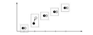
- FIG. 3 shows an example of the result of associating a plurality of temporal images with each other using the normalized phase parameters.
- the first phase parameter is a black dot and the second phase parameter is a white dot, and the graphs are arranged in time sequence from the left.
- the number of time phases of the first moving image and the second moving image is 5 time phases
- the first phase parameter is ⁇ 0.0, 0.3, 0.6, sequentially from the first time phase.
- 0.8, 1.0 ⁇ and the second phase parameter is ⁇ 0.0, 0.5, 0.6, 0.8, 1.0 ⁇ .
- the first moving image and the second moving image are sequentially set to 1 from the first time phase.
- the correspondence is made in a pair, and the corresponding number of time phases is five.
- both the second phase parameter (0.5) and the third phase parameter (0.6) of the second phase parameter are the first.
- Is associated with the third phase (0.6) of the phase parameter of, and the associated number of phases is 5 phases.
- phase parameters of one of the plurality of time phases are the most similar to the same time phase of the other, only one pair with the most similar phase parameters may be associated.
- other time phases that have not been associated may be associated with time phases having similar second and subsequent phase parameters, or may not be used in subsequent steps without being associated.
- the second phase parameter is used as the reference and the second phase time of the first phase parameter and the second phase parameter is used. Is not associated, and the associated number of time phases is four time phases.
- the normalized parameters can be used to associate a plurality of temporal images obtained from the first moving image with a plurality of temporal images obtained from the second moving image.
- the time phases may be associated with each other based on the first phase parameter and the second phase parameter without normalization.
- the first phase parameter and the second phase parameter are calculated using approximately the same part of the subject between the first moving image and the second moving image, the phase is not normalized.
- Time phases with similar parameters can be associated as time phases with similar ventilation volumes.
- the device coordinate system that can be acquired from the header information of the moving image is used to determine the body surface position of the chest and abdomen at the position where the device coordinate system is the same on the first moving image and the second moving image.
- the second phase parameter time phases having similar phase parameters (positions on the body surface are close) may be associated between the first moving image and the second moving image without normalizing the phase parameter.
- the maximum inspiratory position is called the reference phase and the maximum expiratory position is called the comparison phase.
- the respective time phase images of the first moving image and the second moving image that are associated with each other as the maximum intake position which is the reference phase are referred to as the first reference image and the second reference image, respectively.
- the respective time phase images of the first moving image and the second moving image associated with each other as the maximum expiratory position which is the comparison phase are referred to as the first comparison image and the second comparison image, respectively.
- the maximum expiratory position may be used as the reference phase and the maximum inspiratory position may be used as the comparison phase, or another phase acquired from each of the first moving image and the second moving image may be assigned as the reference phase or the comparison phase. Good.
- step S230 the combined position acquisition unit 140, in each time phase associated in step S220, the first time phase image obtained from the first moving image and the second time phase obtained from the second moving image.
- the position where the image is combined is calculated as the combined position information. That is, the combined position acquisition unit 140 acquires combined position information for acquiring combined position information between the first reference image obtained from the first moving image and the second reference image obtained from the second moving image. It corresponds to an example of means. Then, the calculated combined position information is output to the combined image generation unit 150.
- the combination position can be calculated by a known image processing method by performing a search so that pixels representing the same position between the first time phase image and the second time phase image substantially match. For example, a slice position where the image similarity between tomographic images at a predetermined slice position is high is searched for.
- a well-known method such as generally used Sum of Squared Difference (SSD), mutual information, and cross correlation coefficient can be used.
- the bond position information can be calculated as the bond position information.
- the movement of the lung in the cranio-caudal direction from the reference phase to the comparison phase is substantially one direction, and when searching for the slice position P1_i corresponding to the slice position P1_i in each time phase, the value of j when i is a fixed value Is expected to change monotonically in one direction or hardly change. That is, for example, when only one temporal phase shows a binding position that is significantly different from other temporal phases, it is possible that the calculation result of the binding position of that temporal phase is erroneous, and the reliability of the binding position is low. ..
- the combined position acquisition unit 140 calculates the reliability of the combined position of the time phase image obtained from the first moving image and the time phase image obtained from the second moving image that are associated by the associating unit. It corresponds to an example of means.
- step S240 the combined image generation unit 150 generates a combined image in which the first time phase image and the second time phase image are combined based on the combination position of each time phase calculated in step S230. Then, the generated combined image is output to the deformation information estimation unit 160 and the display control unit 180.
- the combined image generation unit 150 combines the combined image based on the combined position calculated in step S230 so that the position on the first temporal image and the corresponding position on the second temporal image overlap each other. To generate. This will be specifically described with reference to FIG. In FIG. 4, the image 400 represents the coronal section of the first temporal image, and the broken line 410 represents the slice position P1_i. The image 420 represents the coronal section of the second temporal image, and the broken line 430 represents the slice position P2_j corresponding to the slice position P1_i calculated in step S230.
- the image 440 is a combined image obtained by translating and combining the second temporal image in the slice direction so that the slice position P1_i of the first temporal image and the slice position P2_j of the second temporal image overlap.
- An area 450 is an area captured only in the first temporal image
- an area 460 is an area captured in both the first temporal image and the second temporal image
- an area 470 is in the second temporal image.
- region currently imaged only in the time phase image is shown.
- the pixel values of the combined image in the regions 450 and 470 are the pixel values of one of the first temporal image and the second temporal image.
- the pixel value of the combined image in the area 460 may be either one of the pixel values of the first temporal image and the second temporal image, or may be the average value. Further, depending on the position in the region 460, the pixel value weight of the first temporal image is increased for the pixels on the lung apex side, and the pixel value weight of the second temporal image is increased for the pixels on the lung bottom side. You may use the weighted average value which made large.
- whether or not to generate a combined image may be determined based on the reliability of the combined position calculated in step S230.
- the reliability of the combined position is calculated, it is determined whether or not it is equal to or higher than a predetermined threshold value set in advance, and only when the reliability is higher than the threshold value, it is determined that the reliability of the combined position is high and a combined image is generated.
- the combined image may be generated by selecting a set of temporal images whose calculated reliability of the combined position is equal to or higher than a predetermined threshold value from the temporal image sets associated in step S220. It should be noted that the selection of the set of temporal images for generating the combined image may be performed by the user or may be automatically selected based on the reliability.
- the combined image generation unit 150 corresponds to an example of a generation unit that selects at least two sets of temporal images whose reliability is equal to or higher than a threshold value and generates a combined image.
- the combined image is generated by translationally moving the slice position P1_i of the first temporal image and the corresponding slice position P2_j of the second temporal image so as to overlap each other.
- the second deformed image may be deformed and combined so that the pixels overlap at the combining position.
- the combined image is generated by translating the slice position P1_i of the first time phase image and the slice position P2_j of the second time phase image corresponding to each other so as to overlap with each other, the body surface position, the position of the branch of the bronchus, etc.
- the second temporal images may be deformed so that the predetermined parts of the two are matched and then combined.
- a time-series combined image including the entire region to be observed can be acquired.
- a combined image obtained by combining the first reference image and the second reference image, which are reference phases is referred to as a reference combined image (or first combined image).
- a combined image obtained by combining the first comparative image and the second comparative image, which are comparison phases, is called a comparative combined image (or a second combined image).
- step S250 the deformation information estimation unit 160 aligns the combined images of the plurality of time phases and estimates the deformation information indicating the time-series deformation of the subject. Then, the estimated deformation information is output to the slip degree calculating unit 170.
- the deformation information is obtained by a known image processing method. For example, it is obtained by transforming one image so that the image similarity between the transformed images becomes high.
- a deformation model based on a radial basis function such as Thin Plate Spline (TPS) or a known deformation model such as Free Form Deformation (FFD) can be used.
- Deformation information may be estimated so that the anatomical feature points do not substantially match the image similarity.
- feature points may be set on the branches of the bronchi and blood vessels in the lung region and the ribs and sternum outside the lung region, and the movement amount of the feature points may be estimated as the deformation information.
- the deformation information estimates the time-series motion between the reference combined image that is the combined image in the reference phase and the comparative combined image that is the combined image in the comparison phase by performing all the registrations of the combined images between the adjacent time phases. To do. Note that, for example, when at least one of the reference combined image and the comparative combined image is a combined image in another time phase different from the reference phase and the comparison phase in step S240, the target of time-series motion estimation is the reference combined image.
- the time series between the image and the comparative combined image is not limited.
- the deformation information may be estimated using only some time phases thinned out at a predetermined interval.
- the deformation between the reference combined image and the comparative combined image may be directly obtained.
- the deformation information is represented by, for example, a displacement vector field from the reference combined image to the comparative combined image.
- the combined image used for estimating the deformation information may be selected based on the reliability of the combined position calculated in step S230. If the combined position is incorrect, anatomical inconsistency may occur near the combined position in the combined image. Therefore, when the reliability of the combined position is calculated, it is determined whether or not the deformation information is equal to or more than a predetermined threshold value set in advance, and only when it is equal to or more than the threshold value, the deformation information is accurately calculated by selecting the image to be used for estimating the deformation information. It can be well estimated.
- step S240 if at least one combined image is thinned out based on the reliability, the deformation information cannot be estimated unless there are two or more combined images. Therefore, three or more combined images are generated in step S240. It is desirable that
- the deformation information estimation unit 160 selects two or more combined images whose reliability is equal to or higher than a threshold value from the three or more combined images, and estimates the deformation information from the selected combined images.
- the number of combined images generated in step S240 may be two.
- deformation information can be estimated using only a highly reliable combined image, so the slip degree can be calculated with high accuracy in the subsequent processing.
- step S260 the slippage calculating unit 170 calculates the slippage at each position near the contour of the target organ based on the deformation information estimated in step S250. That is, the slip degree calculating unit 170 corresponds to an example of a slip degree calculating unit that calculates the slip degree of the object based on the deformation information estimated from the first combined image and the second combined image. Then, the calculated slip degree is output to the display control unit 180.
- the degree of slippage calculates how much the pixels near the contour of the target region in the region of the target organ extracted in step S205 slide with respect to the neighboring pixels outside the region of the target organ. Seek by. For example, as shown in FIG. 5, two pixels, ie, a pixel 520 in the lung region and a pixel 530 outside the region, which are adjacent to the contour line 510 of the lung region in the reference phase combined image 500 (reference combined image) in the normal direction, are provided. One pixel is set as a reference point.
- the norm of the difference of the deformation information (vector) between the combined image (reference combined image) in the reference phase of the two set reference points and the combined image (comparative combined image) in the comparison phase is set to the relevant norm of the target organ. It can be calculated as the slip degree at the position. That is, the degree of slippage corresponds to an example of a relative movement amount between a reference point set inside the lung region and a reference point set outside the lung region with the contour line as a reference.
- the norm of the deformation information may be the norm of the difference between the vectors along the surface of the contour of the lung.
- the number of reference points to be set is an example, and is not limited to the above. Further, one of the two corresponding reference points may be set on the contour line.
- the degree of slip does not necessarily have to be obtained from the deformation information between the reference phase and the comparison phase, and the deformation information calculated from the time phase image of any phase between them can be used.
- the method of calculating the degree of slippage is not limited to this, and a known image processing method may be used.
- step S270 the display control unit 180 visualizes the slip degree calculated in step S260 and displays it on the display unit 12.
- a slip degree map can be generated and displayed on the display unit 12.
- the slippage map is, for example, an image in which a pixel at a contour position of the lung has a grayscale value or a color scale value corresponding to the slippage as a pixel value, and is displayed in parallel with a reference phase combined image (reference combined image). It may be displayed in a superimposed manner. Further, the combined image other than the reference phase may be displayed in parallel or may be displayed in a superimposed manner. In this case, it is desirable to perform coordinate conversion of the slip degree map so that the position matches the combined image other than the reference phase. Further, the combined images of a plurality of time phases may be displayed in parallel or may be displayed in a superimposed manner.
- step S260 may be displayed as moving images that are continuously switched. Further, it may be displayed in parallel with the first moving image or the second moving image which is the input image, or may be displayed in a superimposed manner. Also in this case, it is desirable to display the slip degree map spatially aligned with the first moving image and the second moving image.
- the process of displaying the slippage is not always necessary, and the slippage information calculated in step S260 may be output to the data server 11 and stored.
- the slippage degree in the vicinity of the contour of the entire region of the observation target is accurately determined. It can be calculated well. More specifically, when the two reference points set across the contour line are set near the boundary of the moving image, the position of the reference point after the phase change may not be within the imaging range. ..
- the sensor size of the CT device is about the size of the heart. Therefore, in order to image the entire region of the lung, which has a volume larger than that of the heart, it is divided into upper and lower parts in the caudal-tail direction. There is a need to. Therefore, it is difficult to calculate the slippage degree in the vicinity of the boundary that is a combination target of the images captured by dividing.
- the position of the reference point after the phase change falls within an arbitrary combined image by combining a plurality of moving images obtained by dividing the region of the organ.
- the degree of slippage can be accurately calculated based on the deformation information.
- the user can observe the combined image including the entire region to be observed and the degree of slippage.
- the degree of slippage of the entire region of the observation target (lung) can be accurately calculated as described above, it is possible to reduce the possibility that the user mistakenly recognizes adhesion.
- step S230 the slice position P2_j of one second time phase image corresponding to the slice position P1_i of the first time phase image is calculated, but it is not necessarily one position. ..
- the directions of movement inside and outside the lung region are different. Therefore, when the slice position P1_i of the first temporal image and the slice position P2_j of the second temporal image corresponding to the slice position P2_j of the first temporal image are searched using the image similarity, one of the inside and outside of the lung region has a combined position. Even if the correct calculation is possible, the other may not be calculated correctly. Therefore, the lung regions extracted in step S205 may be used to search for a combined position inside and outside the lung region.
- the slice position P1_i of the first temporal image, the slice position P2_k of the second temporal image having a high image similarity in the lung region, and the slice position P2_l having a high image similarity outside the lung region are set.
- the binding position is set.
- the combined image combined at each combining position can be generated. That is, in each time phase, two combined images are generated that are combined at the respective combined positions inside and outside the lung region.
- the deformation information of each combined image is estimated.
- the deformation information estimated inside the lung region and the deformation information estimated outside the region are the deformation information estimated using the combined image obtained by combining the inside of the lung region and the outside of the lung region using the lung region extracted in step S205.
- the deformation information estimated using the combined image obtained by combining may be integrated into one piece of deformation information.
- step S260 the degree of slippage at each position near the contour of the target organ is calculated based on the deformation information estimated inside the lung region and the deformation information estimated outside the lung region.
- the degree of slippage at each position near the contour of the target organ is calculated based on the deformation information obtained by integrating the deformation information estimated inside the lung region and the deformation information estimated outside the lung region.
- the slip degree can be calculated more accurately.
- the deformation information when the deformation information is estimated between the combined images of a plurality of time phases, the deformation information may be estimated inside and outside the lung region. That is, the slippage degree calculating unit 170 calculates the slippage degree of the target object based on the deformation information inside the target object and the deformation information outside the target object estimated from the first combined image and the second combined image. It may be calculated. For example, when estimating the deformation information of the combined image combined at the combining position in the lung region, conditions suitable for observation in the lung region (for example, -600 for the window level (WL) and 1500 for the window width (WW)). Alternatively, the transformation information may be estimated by performing preprocessing such as pixel value conversion.
- the deformation information may be estimated.
- the deformation information can be estimated from the conditions suitable for observation inside and outside the region of the organ to be observed, so that the slip degree can be calculated more accurately.
- the deformation information may be estimated without generating the combined image by replacing steps S230 to S250 with the following process.
- the combined position acquisition unit 140 acquires relative position information of the first reference image included in the first moving image and the second reference image included in the second moving image as combined position information. ..
- the deformation information estimation unit 160 estimates the first deformation information between the first reference image and the first comparison image included in the first moving image, and the second reference image and the second comparison image. Second deformation information between the second comparison image included in the moving image is estimated. Further, the third deformation information between the first reference image and the second comparison image is estimated based on the combined position information.
- the deformation information between the first comparison image and the second reference image is estimated as the third deformation information.
- the deformation information of the part commonly imaged in the first reference image and the second comparison image can be calculated by integrating the combined position information and the second deformation information.
- the modification information similar to the modification information described in step S250 of the first embodiment is estimated. ..
- the common region can be integrated so that the deformation information of the region commonly imaged in the first reference image and the first comparison image is used as the first deformation information.
- the deformation information of the common area of the second reference image and the second comparison image is the second deformation information
- the deformation information of the common area of the first reference image and the second comparison image is the third deformation information. And can be integrated.
- the degree of slippage can be calculated without generating the combined image, so that the memory of the computer required to hold the combined image can be reduced.
- the combined images of a plurality of temporal phases are generated in step S240, but by replacing the processing of steps S230 to S250 with the following processing, the combined image of only one temporal phase is generated and the deformation information is estimated.
- the relative position information of the first reference image and the second reference image is acquired as the combined position information, and the reference combined image obtained by combining the first reference image and the second reference image is obtained based on the combined position information. To generate. Then, the fourth deformation information between the reference combined image and the first comparative image is estimated, and the fifth deformation information between the reference combined image and the second comparative image is estimated.
- the modification information similar to the modification information described in step S250 of the first embodiment is estimated. Specifically, the deformation information of the common area between the reference combined image and the first comparison image is used as the fourth deformation information, and the deformation information of the common area between the combined image and the second comparison image is used as the fifth deformation information. And can be integrated.
- the combined image is generated by combining the temporal images associated with the same phase in the first moving image and the second moving image.
- the image processing apparatus generates an interpolated image between temporal images as necessary, and generates a combined image using the interpolated image.
- the interpolated image whose phase corresponds to that of the first temporal image is generated. Then, a combined image is generated from the first temporal image and the interpolated image.
- an interpolation image having a phase corresponding to that of the first temporal image can be generated from the second moving image, and the user can observe the combined image obtained by combining the temporal images corresponding to the phase. ..
- the organ to be observed is the lung, and the first moving image and the second moving image are four-dimensional CT images.
- the organ to be observed and the imaging device are not limited to this.
- FIG. 6 shows the configuration of the image processing apparatus according to this embodiment.
- the functions of the time phase correspondence information acquisition unit 130 and the interpolation image generation unit 610 will be described below.
- the other configurations have the same functions as those of the first embodiment, and thus the description thereof will be omitted.
- the time phase correspondence information acquisition unit 130 acquires the other interpolation time phase having a phase corresponding to a predetermined time phase image (first time phase image) of either the first moving image or the second moving image. To do.
- the interpolation time phase represents a time phase between consecutive time phases that have been imaged.
- the interpolation image generation unit 610 generates a time phase image (interpolation image) corresponding to the interpolation time phase from time phase images of other time phases.
- FIG. 7 shows a flowchart of the overall processing procedure performed by the image processing device 60. Since steps S700 to S710 and S730 to S770 are the same as steps S200 to S210 and S230 to S270 of the first embodiment, description thereof will be omitted. Only the difference from the flowchart of FIG. 2 will be described below.
- step S720 acquisition of time phase correspondence information
- the time phase correspondence information acquisition unit 130 similar to the process of step S220 in the first embodiment, the first moving image corresponding to the phase based on the first phase parameter and the second phase parameter.
- the image and the time phase image of the second moving image are associated with each other.
- the information indicating the phase similarity is acquired as time phase correspondence information.
- the process of associating with the interpolation time phase is performed.
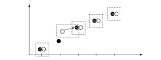
- the first phase parameter is a black dot and the second phase parameter is a white point, and the graphs are arranged in time sequence from the left.
- the time phase image 800 of the fifth time phase of the first moving image is the second moving image. It will not correspond to any of the temporal images.
- the interpolation time phase associated with the time phase image 800 of the fifth time phase of the first moving image is acquired.
- the time phase images of the fourth time phase of the first moving image and the second motion image are associated with each other, and the time phase image 810 of the sixth time phase of the first moving image and the second time moving image
- the time phase image 815 of the fifth time phase is associated.
- the time phase image 800 at the fifth time phase of the first moving image is the subject between the time phase image 805 at the fourth time phase and the time phase image 815 at the fifth time phase of the second moving image.
- Can be estimated to represent the state of. Therefore, the time phase image 800 of the fifth time phase of the first moving image is interpolated between the time phase image 805 of the fourth time phase of the second moving image and the time phase image 815 of the fifth time phase ( For example, 4.5 time phase).
- the interpolation time phase can also be calculated as follows.
- a time phase image of the first moving image and a time phase image of the b time phase of the second moving image are associated with each other, and further, a+c (0 ⁇ c) time phase of the first moving image is associated.
- a time phase image and the time phase image of the b+d (0 ⁇ d) time phase of the second moving image correspond to each other.
- the interpolation time phase b+f (0 ⁇ f ⁇ d) of the second moving image which is associated with the time phase image (0 ⁇ e ⁇ c) of the a+e time phase of the first moving image, is expressed by the equation (1).
- b+f b+d ⁇ e/c (1)
- the method of acquiring the interpolation time phase is not limited to the above method, and the interpolation time phase may be acquired based on the value of the phase parameter, for example.
- the value of the first phase parameter of the time phase image of the a+e time phase of the first moving image is p_e
- the value of the second phase of the b time phase of the second moving image and the second phase image of the b+d time phase of the second moving image is taken as an example.
- the method of acquiring the interpolation time phase of the second moving image corresponding to the predetermined (focused) time phase image of the first moving image has been described.
- the interpolation time phase of the first moving image corresponding to the time phase image may be obtained by a similar method.
- step S725 Generation of interpolation image
- the interpolation image generation unit 610 generates an interpolation image in the interpolation time phase. Then, the generated interpolated image is output to the combined position acquisition unit 140 and the combined image generation unit 150 as the temporal image of the second moving image corresponding to the noted temporal image of the first moving image.
- the interpolation image is generated based on the time-series movement of the subject in the time phase image near the interpolation time phase.
- an interpolation image at the 4.5th time phase which is an interpolation time phase of the second moving image associated with the time phase image at the 5th time phase of the first moving image
- the interpolation image is generated based on the time-series movement between the time phase images of the fourth and fifth time phases, which are the time phase images before and after the 4.5th time phase of the second moving image.
- the deformation information between the fourth time phase and the fifth time phase is estimated, and, for example, one of the images is deformed to generate an interpolated image.
- the deformation information is interpolated to generate an interpolated image representing the state of the subject between the time phase images of the fourth time phase and the fifth time phase.
- the interpolation rate obtained from the interpolation time phase is used as the amount of deformation for transforming the time phase image of the fifth time phase into the time phase image of the fourth time phase.
- An interpolation image is generated by deforming the time phase image of the fifth time phase using the deformation information multiplied by.
- the time phase used when generating the interpolation image does not have to be the image of the adjacent time phase before and after the interpolation time phase.
- the deformation information between the b time phase before the interpolation time phase b+f and the b+d time phase after the interpolation time phase is estimated, and the deformation information obtained by multiplying the deformation amount by the value of (df)/d is used to calculate b+d.
- An interpolation image can also be generated by deforming the time phase image of the time phase. Further, the value (interpolation rate) by which the deformation information is multiplied may be obtained based on the phase parameters in the two time phases for estimating the deformation information.
- the two time phases used when estimating the deformation information do not have to be the time phases before and after the interpolation time phase.
- a case will be described as an example in which an interpolation image of the first moving image having a phase similar to that of the time phase image 825 of the seventh time phase of the second moving image illustrated in FIG. 8 is generated.
- deformation information between the time phase image 810 at the sixth time phase and the time phase image 820 at the seventh time phase of the first moving image is estimated, and the interpolation information is extrapolated to generate an interpolation image. You may.
- the value of the second phase parameter of the time phase image 825 of the seventh time phase of the second motion image is the time phase image of the second time phase and the time phase image of the third time phase of the first motion image. Is a value between the first phase parameters of the temporal image of. Therefore, it can be estimated that the phase is between these two time phases. Therefore, by estimating the deformation information of the time phase image between the second time phase and the third time phase of the first moving image and deforming one of the phase images, An interpolation image of the interpolation time phase of the first moving image corresponding to the phase image 825 of the phase may be generated.
- the method of estimating the deformation information according to the present embodiment may be the same method as step S250 of the first embodiment.
- the technology disclosed in the present specification can be implemented as a system, a device, a method, a program, a recording medium (storage medium), or the like. Specifically, it may be applied to a system including a plurality of devices (for example, a host computer, an interface device, an imaging device, a web application, etc.), or may be applied to a device including one device. good.
- a recording medium or storage medium
- a program code computer program
- such a storage medium is a computer-readable storage medium.
- the computer (or CPU or MPU) of the system or apparatus reads and executes the program code stored in the recording medium.
- the program code itself read from the recording medium realizes the functions of the above-described embodiments
- the recording medium recording the program code constitutes the technology disclosed in this specification.
Landscapes
- Engineering & Computer Science (AREA)
- Physics & Mathematics (AREA)
- Theoretical Computer Science (AREA)
- Computer Vision & Pattern Recognition (AREA)
- General Physics & Mathematics (AREA)
- Health & Medical Sciences (AREA)
- Medical Informatics (AREA)
- Radiology & Medical Imaging (AREA)
- General Health & Medical Sciences (AREA)
- Nuclear Medicine, Radiotherapy & Molecular Imaging (AREA)
- Life Sciences & Earth Sciences (AREA)
- Quality & Reliability (AREA)
- Multimedia (AREA)
- Optics & Photonics (AREA)
- Pathology (AREA)
- Biomedical Technology (AREA)
- Heart & Thoracic Surgery (AREA)
- Molecular Biology (AREA)
- Surgery (AREA)
- Animal Behavior & Ethology (AREA)
- High Energy & Nuclear Physics (AREA)
- Public Health (AREA)
- Veterinary Medicine (AREA)
- Biophysics (AREA)
- Apparatus For Radiation Diagnosis (AREA)
- Image Analysis (AREA)
Abstract
L'invention concerne un dispositif de traitement d'images qui est caractérisé par le calcul précis d'une valeur de glissement même si la région d'un site à observer, comprise dans une plage de capture d'image, est différente dans une pluralité d'images médicales de phases temporelles différentes.
Priority Applications (3)
| Application Number | Priority Date | Filing Date | Title |
|---|---|---|---|
| JP2020563335A JP7536653B2 (ja) | 2018-12-27 | 2019-12-25 | 画像処理装置、画像処理方法及びプログラム |
| US17/346,000 US11836923B2 (en) | 2018-12-27 | 2021-06-11 | Image processing apparatus, image processing method, and storage medium |
| JP2024130996A JP7838036B2 (ja) | 2018-12-27 | 2024-08-07 | 画像処理装置、画像処理方法及びプログラム |
Applications Claiming Priority (2)
| Application Number | Priority Date | Filing Date | Title |
|---|---|---|---|
| JP2018-245138 | 2018-12-27 | ||
| JP2018245138 | 2018-12-27 |
Related Child Applications (1)
| Application Number | Title | Priority Date | Filing Date |
|---|---|---|---|
| US17/346,000 Continuation US11836923B2 (en) | 2018-12-27 | 2021-06-11 | Image processing apparatus, image processing method, and storage medium |
Publications (1)
| Publication Number | Publication Date |
|---|---|
| WO2020138136A1 true WO2020138136A1 (fr) | 2020-07-02 |
Family
ID=71129443
Family Applications (1)
| Application Number | Title | Priority Date | Filing Date |
|---|---|---|---|
| PCT/JP2019/050752 Ceased WO2020138136A1 (fr) | 2018-12-27 | 2019-12-25 | Dispositif de traitement d'image, procédé de traitement d'images et programme |
Country Status (3)
| Country | Link |
|---|---|
| US (1) | US11836923B2 (fr) |
| JP (2) | JP7536653B2 (fr) |
| WO (1) | WO2020138136A1 (fr) |
Cited By (5)
| Publication number | Priority date | Publication date | Assignee | Title |
|---|---|---|---|---|
| JP2022049275A (ja) * | 2020-09-16 | 2022-03-29 | キヤノン株式会社 | 情報処理装置、情報処理方法及びプログラム |
| US20230079025A1 (en) * | 2021-09-10 | 2023-03-16 | Canon Kabushiki Kaisha | Information processing apparatus, information processing method, and non-transitory computer readable medium |
| JP2023040874A (ja) * | 2021-09-10 | 2023-03-23 | キヤノン株式会社 | 情報処理装置、情報処理方法およびプログラム |
| JP2023040913A (ja) * | 2021-09-10 | 2023-03-23 | キヤノン株式会社 | 情報処理装置、情報処理方法およびプログラム |
| JP2025126322A (ja) * | 2021-03-17 | 2025-08-28 | コニカミノルタ株式会社 | 動態画像解析装置及びプログラム |
Citations (5)
| Publication number | Priority date | Publication date | Assignee | Title |
|---|---|---|---|---|
| JP2004000411A (ja) * | 2002-04-03 | 2004-01-08 | Canon Inc | 動画像表示方法、動画像処理方法、プログラム、コンピュータ可読記憶媒体、動画像表示装置、動画像処理装置、動画像表示システム、動画像処理システム、画像診断支援方法、及び画像診断支援システム |
| JP2011255055A (ja) * | 2010-06-11 | 2011-12-22 | Konica Minolta Medical & Graphic Inc | 放射線画像処理装置、放射線画像処理方法及びプログラム |
| JP2016067832A (ja) * | 2014-10-01 | 2016-05-09 | キヤノン株式会社 | 医用画像処理装置、医用画像処理方法 |
| JP2017018317A (ja) * | 2015-07-10 | 2017-01-26 | コニカミノルタ株式会社 | 胸部画像表示システム及び画像処理装置 |
| JP2017225724A (ja) * | 2016-06-24 | 2017-12-28 | コニカミノルタ株式会社 | 放射線画像撮影システム |
Family Cites Families (2)
| Publication number | Priority date | Publication date | Assignee | Title |
|---|---|---|---|---|
| JP6932934B2 (ja) * | 2017-01-23 | 2021-09-08 | セイコーエプソン株式会社 | スキャナー、スキャンプログラムおよびスキャンデータの生産方法 |
| JP7153425B2 (ja) * | 2017-01-23 | 2022-10-14 | セイコーエプソン株式会社 | スキャナー、スキャンプログラムおよびスキャンデータの生産方法 |
-
2019
- 2019-12-25 WO PCT/JP2019/050752 patent/WO2020138136A1/fr not_active Ceased
- 2019-12-25 JP JP2020563335A patent/JP7536653B2/ja active Active
-
2021
- 2021-06-11 US US17/346,000 patent/US11836923B2/en active Active
-
2024
- 2024-08-07 JP JP2024130996A patent/JP7838036B2/ja active Active
Patent Citations (5)
| Publication number | Priority date | Publication date | Assignee | Title |
|---|---|---|---|---|
| JP2004000411A (ja) * | 2002-04-03 | 2004-01-08 | Canon Inc | 動画像表示方法、動画像処理方法、プログラム、コンピュータ可読記憶媒体、動画像表示装置、動画像処理装置、動画像表示システム、動画像処理システム、画像診断支援方法、及び画像診断支援システム |
| JP2011255055A (ja) * | 2010-06-11 | 2011-12-22 | Konica Minolta Medical & Graphic Inc | 放射線画像処理装置、放射線画像処理方法及びプログラム |
| JP2016067832A (ja) * | 2014-10-01 | 2016-05-09 | キヤノン株式会社 | 医用画像処理装置、医用画像処理方法 |
| JP2017018317A (ja) * | 2015-07-10 | 2017-01-26 | コニカミノルタ株式会社 | 胸部画像表示システム及び画像処理装置 |
| JP2017225724A (ja) * | 2016-06-24 | 2017-12-28 | コニカミノルタ株式会社 | 放射線画像撮影システム |
Cited By (8)
| Publication number | Priority date | Publication date | Assignee | Title |
|---|---|---|---|---|
| JP2022049275A (ja) * | 2020-09-16 | 2022-03-29 | キヤノン株式会社 | 情報処理装置、情報処理方法及びプログラム |
| JP7546423B2 (ja) | 2020-09-16 | 2024-09-06 | キヤノン株式会社 | 情報処理装置、情報処理方法及びプログラム |
| JP2025126322A (ja) * | 2021-03-17 | 2025-08-28 | コニカミノルタ株式会社 | 動態画像解析装置及びプログラム |
| US20230079025A1 (en) * | 2021-09-10 | 2023-03-16 | Canon Kabushiki Kaisha | Information processing apparatus, information processing method, and non-transitory computer readable medium |
| JP2023040874A (ja) * | 2021-09-10 | 2023-03-23 | キヤノン株式会社 | 情報処理装置、情報処理方法およびプログラム |
| JP2023040913A (ja) * | 2021-09-10 | 2023-03-23 | キヤノン株式会社 | 情報処理装置、情報処理方法およびプログラム |
| JP7781573B2 (ja) | 2021-09-10 | 2025-12-08 | キヤノン株式会社 | 情報処理装置、情報処理方法およびプログラム |
| JP7781572B2 (ja) | 2021-09-10 | 2025-12-08 | キヤノン株式会社 | 情報処理装置、情報処理方法およびプログラム |
Also Published As
| Publication number | Publication date |
|---|---|
| US11836923B2 (en) | 2023-12-05 |
| JP7838036B2 (ja) | 2026-03-31 |
| US20210304409A1 (en) | 2021-09-30 |
| JP7536653B2 (ja) | 2024-08-20 |
| JPWO2020138136A1 (ja) | 2021-11-11 |
| JP2024156932A (ja) | 2024-11-06 |
Similar Documents
| Publication | Publication Date | Title |
|---|---|---|
| JP7536653B2 (ja) | 画像処理装置、画像処理方法及びプログラム | |
| US8867808B2 (en) | Information processing apparatus, information processing method, program, and storage medium | |
| JP6346445B2 (ja) | 処理装置、処理装置の制御方法、およびプログラム | |
| KR101982149B1 (ko) | 의료 영상의 일부 정보를 활용한 장기 영상 생성 방법 및 장치 | |
| KR102338018B1 (ko) | 초음파 이미지상의 특징점들을 이용한 초음파 지방간 자동 진단 장치 및 이를 이용한 원격 의료 진단 방법 | |
| JP5812841B2 (ja) | 画像診断支援装置、画像診断支援方法、画像診断支援プログラム | |
| JP6541334B2 (ja) | 画像処理装置、画像処理方法、およびプログラム | |
| JP2012205899A (ja) | 3次元的モデルを利用した身体臓器の映像生成方法及び装置並びにコンピュータ読み取り可能な記録媒体 | |
| KR20120111871A (ko) | 3차원적 모델을 이용한 신체 장기의 영상 생성 방법 및 장치 | |
| JP6131161B2 (ja) | 画像位置合わせ装置、方法、およびプログラム、並びに3次元変形モデル生成方法 | |
| US11062452B2 (en) | Image processing apparatus, image processing method and non-transitory computer-readable medium | |
| KR20140096919A (ko) | 의료 영상 정합 방법 및 장치 | |
| KR20240086195A (ko) | 확산 모델을 이용한 비지도 학습 기반 변형 영상 정합 및 합성 영상 생성 시스템 및 그 방법 | |
| JP2015130973A (ja) | 処理装置、処理方法、およびプログラム | |
| JP2002140689A (ja) | 医用画像処理装置及びその方法 | |
| KR20130079987A (ko) | 장기 변형모델을 추정하는 방법, 장치 및 의료영상시스템 | |
| JP7551419B2 (ja) | 情報処理装置、情報処理方法及びプログラム | |
| JP2017080157A (ja) | 画像処理装置 | |
| US12347118B2 (en) | Information processing apparatus, information processing method, and non-transitory storage medium for processing image features of anatomical parts from examination images of a subject | |
| JP6501569B2 (ja) | 画像処理装置、画像処理方法、及びプログラム | |
| US10299864B1 (en) | Co-localization of multiple internal organs based on images obtained during surgery | |
| JP6660428B2 (ja) | 処理装置、処理方法、およびプログラム | |
| JP7500360B2 (ja) | 情報処理装置、情報処理方法、及びプログラム | |
| JP7546423B2 (ja) | 情報処理装置、情報処理方法及びプログラム | |
| JP7556715B2 (ja) | 情報処理装置、情報処理方法、及びプログラム |
Legal Events
| Date | Code | Title | Description |
|---|---|---|---|
| 121 | Ep: the epo has been informed by wipo that ep was designated in this application |
Ref document number: 19902319 Country of ref document: EP Kind code of ref document: A1 |
|
| ENP | Entry into the national phase |
Ref document number: 2020563335 Country of ref document: JP Kind code of ref document: A |
|
| NENP | Non-entry into the national phase |
Ref country code: DE |
|
| 122 | Ep: pct application non-entry in european phase |
Ref document number: 19902319 Country of ref document: EP Kind code of ref document: A1 |