WO2020138255A1 - 開大器 - Google Patents
開大器 Download PDFInfo
- Publication number
- WO2020138255A1 WO2020138255A1 PCT/JP2019/051056 JP2019051056W WO2020138255A1 WO 2020138255 A1 WO2020138255 A1 WO 2020138255A1 JP 2019051056 W JP2019051056 W JP 2019051056W WO 2020138255 A1 WO2020138255 A1 WO 2020138255A1
- Authority
- WO
- WIPO (PCT)
- Prior art keywords
- blade
- opening
- portions
- pair
- angle
- Prior art date
- Legal status (The legal status is an assumption and is not a legal conclusion. Google has not performed a legal analysis and makes no representation as to the accuracy of the status listed.)
- Ceased
Links
Images


Classifications
-
- A—HUMAN NECESSITIES
- A61—MEDICAL OR VETERINARY SCIENCE; HYGIENE
- A61B—DIAGNOSIS; SURGERY; IDENTIFICATION
- A61B17/00—Surgical instruments, devices or methods
- A61B17/56—Surgical instruments or methods for treatment of bones or joints; Devices specially adapted therefor
- A61B17/58—Surgical instruments or methods for treatment of bones or joints; Devices specially adapted therefor for osteosynthesis, e.g. bone plates, screws or setting implements
- A61B17/88—Osteosynthesis instruments; Methods or means for implanting or extracting internal or external fixation devices
- A61B17/8866—Osteosynthesis instruments; Methods or means for implanting or extracting internal or external fixation devices for gripping or pushing bones, e.g. approximators
-
- A—HUMAN NECESSITIES
- A61—MEDICAL OR VETERINARY SCIENCE; HYGIENE
- A61B—DIAGNOSIS; SURGERY; IDENTIFICATION
- A61B17/00—Surgical instruments, devices or methods
- A61B17/56—Surgical instruments or methods for treatment of bones or joints; Devices specially adapted therefor
- A61B17/58—Surgical instruments or methods for treatment of bones or joints; Devices specially adapted therefor for osteosynthesis, e.g. bone plates, screws or setting implements
- A61B17/88—Osteosynthesis instruments; Methods or means for implanting or extracting internal or external fixation devices
- A61B17/8872—Instruments for putting said fixation devices against or away from the bone
-
- A—HUMAN NECESSITIES
- A61—MEDICAL OR VETERINARY SCIENCE; HYGIENE
- A61B—DIAGNOSIS; SURGERY; IDENTIFICATION
- A61B17/00—Surgical instruments, devices or methods
- A61B17/56—Surgical instruments or methods for treatment of bones or joints; Devices specially adapted therefor
- A61B17/58—Surgical instruments or methods for treatment of bones or joints; Devices specially adapted therefor for osteosynthesis, e.g. bone plates, screws or setting implements
- A61B17/68—Internal fixation devices, including fasteners and spinal fixators, even if a part thereof projects from the skin
- A61B17/80—Cortical plates, i.e. bone plates; Instruments for holding or positioning cortical plates, or for compressing bones attached to cortical plates
- A61B17/8095—Wedge osteotomy devices
-
- A—HUMAN NECESSITIES
- A61—MEDICAL OR VETERINARY SCIENCE; HYGIENE
- A61B—DIAGNOSIS; SURGERY; IDENTIFICATION
- A61B17/00—Surgical instruments, devices or methods
- A61B17/56—Surgical instruments or methods for treatment of bones or joints; Devices specially adapted therefor
- A61B17/58—Surgical instruments or methods for treatment of bones or joints; Devices specially adapted therefor for osteosynthesis, e.g. bone plates, screws or setting implements
- A61B17/88—Osteosynthesis instruments; Methods or means for implanting or extracting internal or external fixation devices
- A61B17/92—Impactors or extractors, e.g. for removing intramedullary devices
-
- A—HUMAN NECESSITIES
- A61—MEDICAL OR VETERINARY SCIENCE; HYGIENE
- A61B—DIAGNOSIS; SURGERY; IDENTIFICATION
- A61B90/00—Instruments, implements or accessories specially adapted for surgery or diagnosis and not covered by any of the groups A61B1/00 - A61B50/00, e.g. for luxation treatment or for protecting wound edges
- A61B90/06—Measuring instruments not otherwise provided for
- A61B2090/067—Measuring instruments not otherwise provided for for measuring angles
Definitions
- the present disclosure relates to Kaidaiki.
- High Tibial Osteotomy to correct varus deformity (so-called O-leg) and valgus deformity (so-called X-leg) for the treatment of osteoarthritis of the knee.
- DFO Distal Femoral Osteotomy
- Patent Document 1 discloses a large opener including one blade composed of a pair of swinging members (arm portions) whose tips are rotatably connected to each other, and a pair of opening/closing members for opening and closing the blades. Such an invention is disclosed.
- Patent Document 2 two blades each having a pair of long rocking members whose tips are rotatably connected to each other and detachably combined, and two opening/closing mechanisms for opening and closing these two blades are disclosed. And a pair of swing members of one of the blades is provided with a protrusion (engaging portion) that engages with the recess of the other pair of swing members when combined with the other blade.
- a big instrument is disclosed.
- Patent Documents 3 to 6 two blades each having two long swinging members whose tips are rotatably connected to each other, and an opening/closing mechanism that collectively opens and closes these two blades are disclosed.
- a provided opener is disclosed.
- the two blades are connected by the connecting member and are collectively opened/closed by one opening/closing mechanism, so that the load is concentrated on one location of the blades. Can be suppressed.
- a long driver or a hexagon wrench is used to rotate the driver at a position far from the blade to operate the opening/closing mechanism, so that the force transmission to the opening/closing mechanism is good. It may not be possible to do so, or an excessive load may be applied to the connection portion between the driver or the hexagon wrench and the opening/closing mechanism, and the durability of these may be affected. Since a connecting member that connects one of the swinging members to each other is struck by a plastic hammer or the like and inserted into the cut, it is difficult to apply a struck force in a well-balanced manner.
- Patent Documents 3, 5 and 6 since two blades are interlocked to expand the size, the expansion angles of the front and the rear of the bone cutting portion as in Non-Patent Document 1 are separately set. There is also a problem that it is not suitable for cases that require adjustment.
- the invention described in Patent Document 4 has a problem that a complicated operation mechanism and a driver in which gears are combined to open and close the opening device are required, and the number of parts is large.
- Japanese Patent No. 4468635 Japanese Patent No. 4736091 JP, 2016-209435, A JP, 2017-46783, A Japanese Patent Laid-Open No. 2018-175828 Japanese Patent Laid-Open No. 2018-192066
- the present disclosure has been made in view of the above circumstances, and can open and close a plurality of blades collectively or individually and easily and smoothly, has excellent operability and durability, and has a simple configuration. It is possible to provide a big instrument.
- an opening device includes an opening device body having a first blade and a second blade that can be arranged in parallel with the first blade, the first blade and the second blade.
- An opening/closing mechanism for opening and closing a blade wherein the first blade and the second blade have a pair of arm portions whose tip portions are connected to each other so as to be rotatable and movable in a separation direction and a proximity direction, and a pair of the arm portions.
- An angle adjusting unit for adjusting an angle between the shafts, and the opening/closing mechanism includes a plurality of shafts rotatably connected by a support shaft, and each shaft has a handle portion on one end side via the support shaft.
- Is configured to have an operating portion that operates in conjunction with the handle portion on the other end side, and the operating portion of each shaft has a base end portion of one or the other arm portion of the first blade, And/or an engaging portion that engages with a base end portion of the arm portion of one or the other of the second blades is provided.
- FIG. 1 It is a top view of the component of the large opening device which concerns on 1st Embodiment. It is a side view (pushing screw is abbreviate
- FIG. 6 is a plan view showing a state in which an open state of the arm portion of the first blade is held by the angle adjusting portion.
- FIG. 9 is a plan view showing a state in which the angle adjusting unit holds the open state of the arm portions of the first blade and the second blade. It is a figure which shows the state which removed the 2nd blade from the notch.
- FIG. 14B is a view taken in the direction of arrow A in FIG. 14A in a state where the opening/closing mechanism of the large opening device according to the fifth embodiment is closed.
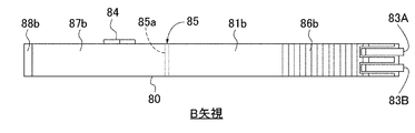
- FIG. 14A It is a B arrow line view of FIG. 14A in the state which the opening/closing mechanism of the large opening device which concerns on 5th Embodiment was closed. It is a top view showing the state where the 1st and 2nd opening-and-closing mechanism of the opening device concerning a 6th embodiment was piled up in parallel and arranged. It is a side view showing the state where the 1st and 2nd opening-and-closing mechanism of the opening device concerning a 6th embodiment was separated. It is a top view showing the state where the 1st and 2nd opening-and-closing mechanism of the opening device concerning a 7th embodiment was piled up in parallel, and was connected by an engaging mechanism.
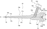
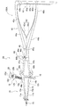
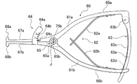
- FIG. 1 is a plan view of constituent members of the opening device 100 according to the first embodiment.
- the opening device 100 according to the first embodiment opens and closes the opening device body 30 having the first blade 10 and the second blade 20, and the first blade 10 and the second blade 20.
- An opening/closing mechanism (large opening handle) 40 is provided.
- the opening device 100 according to the first embodiment is a driving member (driving handle) 50 for driving the first blade 10 and the second blade 20 into the notch 2 (see FIG. 3A etc.) formed in the bone 1. Is equipped with.
- the open device 100 is used, for example, for surgery on the bone 1 such as a high tibial osteotomy (HTO).
- the opening device 100 is inserted into the cut portion 2 in a state in which the first blade 10 and the second blade 20 of the opening device body 30 are stacked in parallel (see FIG. 2A), and the cutting portion 2 is enlarged to make it artificial.
- It is an instrument for forming a space for inserting an implant such as a bone.
- a configuration including the opening device main body 30 having the first and second blades 10 and 20, the opening/closing mechanism 40, and the driving member 50 as necessary is provided.
- a “open device” it is not limited to such a classification.
- the main body 30 of the opener is referred to as "opener”
- the configuration including this "opener”, the opening/closing mechanism 40, and the driving member 50 as necessary is classified as "opener set”. You can also do it.
- the side to be inserted into the cut portion 2 is referred to as a “tip”, and the opposite side is the hand of a practitioner such as a doctor who operates the dilator 100.
- the side is called the "proximal end”.
- the direction in which the opening device body 30 extends (the direction parallel to the center line O shown in FIG. 2B) is called the “longitudinal direction”, and the opening direction is called the "width direction”.
- the direction orthogonal to the “longitudinal direction” and the “width direction” (the direction of the axis I of the support shafts 16a and 26a shown in FIG. 2A) is referred to as the “height direction” or the “arrangement direction”.
- each of the pair of members facing outward is referred to as an “outer surface”, and the side surface facing the opposite side (inward) is referred to as an “inner surface”.
- the surface on the front side of the paper is referred to as “front side” and the surface on the back side of the paper is referred to as “back side”.
- the first blade 10 includes a pair of arm portions 11a and 11b.
- the pair of arm portions 11a and 11b have base end portions 14a and 14b to which the opening/closing mechanism 40 and the driving member 50 are attached, and insertion portions 15a and 15b to be inserted into the cut portion 2 of the bone 1.
- the base end portions 14a and 14b are provided with an angle adjusting portion 12 and an engaged portion 13.
- the connecting portion 16 is configured to have a pin-shaped support shaft 16a and a bearing that rotatably supports the support shaft 16a, and has a so-called pivot structure. With this configuration, the pair of arm portions 11a and 11b can be rotationally moved in the separating direction and the approaching direction with the support shaft 16a as the rotation shaft.
- the connecting portion 16 is not limited to the pivot structure, and may have any known configuration.
- the pair of arms 11a and 11b are made of a long metal member, and the thickness in the height direction indicated by “t” in FIG. 2A is the same from the tip to the base. With this configuration, the arm portions 11a and 11b can be provided with excellent strength against a driving operation and an opening operation. Further, the first blade 10 and the second blade 20 can be arranged in parallel in the axis I direction (height direction).
- the base end portions 14a and 14b are wider than the insertion portions 15a and 15b.
- the base end portions 14a and 14b are provided with appropriate strength that can withstand driving and opening operations.
- the widths of the insertion portions 15a and 15b are gradually narrowed from the base end portions 14a and 14b toward the distal end, and have a tapered shape (wedge shape). With such a tapered shape, the insertion portions 15a and 15b can be easily inserted into the cut portion 2.
- angle between the outer surfaces of the arm portions 11a and 11b in the closed state is 5°. That is, the initial value (minimum value) of the angle ⁇ 1 of the arm portions 11a and 11b is 5°. The same applies to the angle ⁇ 2 between the arm portions 21a and 21b of the second blade 20.
- the minimum values of the angles ⁇ 1 and ⁇ 2 are not limited to 5°.
- the minimum values of the angles ⁇ 1 and ⁇ 2 can be set arbitrarily.
- the angle adjusting unit 12 is a member that adjusts the angle ⁇ 1 between the pair of arms 11a and 11b that opens and closes via the connecting unit 16 and holds the adjusted angle ⁇ 1.
- the angle adjusting part 12 is configured to have a screw hole 12a provided in the base end part 14a of the one arm part 11a and a push screw 12b fastened to the screw hole 12a.
- the screw hole 12a is provided so as to penetrate from the outer surface to the inner surface of the base end portion 14a.
- the pair of arm portions 11a and 11b can be closed as shown in FIG. 2B.
- the push screw 12b is rotated in the fastening direction (the direction of inserting into the screw hole 12a) so that the tip of the push screw 12b protrudes from the screw hole 12a.
- the angle ⁇ 1 between the pair of arm portions 11a and 11b can be adjusted by adjusting the insertion amount of the push screw 12b into the screw hole 12a.
- the tip of the push screw 12b has a hemispherical shape. Further, a concave groove 12c for accommodating the tip of the push screw 12b is provided along the longitudinal direction on the inner surface of the other arm portion 11b with which the tip of the push screw 12b contacts.
- anti-slip portions 17a and 17b are provided on the outer side surfaces of the arm portions 11a and 11b, respectively.
- the anti-slip portions 17 a, 17 b are composed of a plurality of groove portions provided so as to intersect with the insertion direction into the cut portion 2.
- the engaged portion 13 includes a pair of engaging protrusions 131a and 131b, a pair of engaging concave grooves 132a and 132b, one ball receiving portion 133, and a pair of engaging protrusions.
- the recesses 134a and 134b are provided.
- the pair of engagement protrusions 131a and 131b are provided so that the base end sides of the base end portions 14a and 14b project in the width direction.
- the pair of engagement concave grooves 132a and 132b are rectangular in plan view, and are formed by recessing the outer side surfaces of the pair of engagement protrusions 131a and 131b parallel to the axis I.
- the ball receiving portion 133 is formed by recessing the outer surface of one engagement protrusion 131a into a hemispherical shape.
- the pair of engagement recesses 134a and 134b have a base end portion 14a, 14b so as to have a substantially T shape (or a substantially arrow shape) in plan view when the arm portions 11a, 11b are closed.
- the inner surface of the is recessed. With this shape, it is possible to rationally prevent accidental omission of engagement protrusions 48a and 48b of the opening/closing mechanism 40, which will be described later, engaged with the engagement recesses 134a and 134b.
- the pair of engagement protrusions 131a and 131b are housed in a housing recess 53 of the driving member 50 described later.
- the engagement protrusions 55a and 55b of the driving member 50 engage with the pair of engagement grooves 132a and 132b.
- One ball plunger 56 a of the driving member 50 engages with the ball receiving portion 133.
- the engaging recesses 134a and 134b mainly engage with engaging protrusions 48a and 48b of the opening/closing mechanism 40, which will be described later, but also the engaging protrusion 54 of the driving member 50.
- the second blade 20 has the same basic configuration as the first blade 10 except that a push screw 22b that is longer than the push screw 12b of the first blade 10 is used. Further, the shape and dimensions of the constituent members other than the push screw 12b are the same as those of the first blade 10. However, the same screw may be used for the push screw 12b and the push screw 22b, and the manufacturing process and the like can be further simplified by eliminating the distinction between the first and second blades 10 and 20.
- first blade 10 and the second blade 20 are provided with the same configuration, they can be manufactured in the same process using the same mold, and the productivity and the like can be improved.
- constituent members of the second blade 20 will be briefly described, and detailed description thereof will be omitted.
- the second blade 20 includes a pair of arm portions 21a and 21b having base end portions 24a and 24b and insertion portions 25a and 25b, and the base end portions 24a and 24b.
- the angle adjusting portion 22 and the engaged portion 23 are provided.
- the tips of the pair of arm portions 21a and 21b are rotatably and movably connected by a connecting portion 26 having a pivot structure having a support shaft 26a and a bearing.
- the thickness in the height direction of the pair of arm portions 21a, 21b is the same from the tip to the base end, and the thickness in the width direction is thicker at the base end portions 24a, 24b than at the insertion portions 25a, 25b.
- the insertion portions 25a and 25b are gradually thinned from the base end portion 24b side toward the distal end, and have a tapered shape (wedge shape).
- anti-slip portions 27a and 27b formed of a plurality of groove portions are provided on both outer side surfaces of the pair of arm portions 21a and 21b.
- the angle adjusting portion 22 is a member that adjusts the angle ⁇ 2 between the pair of arm portions 21a and 21b, and includes a screw hole 22a provided at the base end portion 24a of one arm portion 21a, a push screw 22b, and a groove. 22c.
- the push screw 22b is longer than the push screw 12b. Therefore, as shown in FIG. 3A, when the first blade 10 and the second blade 20 are arranged in parallel, the heads 12d and 22d of the push screws 12b and 22b are displaced from each other without interfering with each other. Thus, the push screws 12b and 22b can be easily rotated.
- the first blade 10 and the second blade 20 may be stacked so that the push screws 12b and 22b project in different directions.
- the practitioner can rotate the push screws 12b and 22b from two opposite directions.
- the first and second blades 10 and 20 have a pair of arm portions 11a, 11b, 21a and 21b formed line-symmetrically with respect to a center line O. Therefore, depending on the site to be operated, the operability of the practitioner, and the like, the angle adjusting sections 12 and 22 can be overlapped in either the same orientation or different orientations.
- the engaged portion 23 has a pair of engaging protrusions 231a and 231b, a pair of engaging concave grooves 232a and 232b, a ball receiving portion 233, and a pair of engaging concave portions 234a and 234b. Composed.
- the opening/closing mechanism 40 is a member that collectively opens and closes the first and second blades 10 and 20 of the opening device main body 30.
- the opening/closing mechanism 40 includes a pair of shafts 41a and 41b, a biasing means 42, a ratchet mechanism 43, and an angle scale member (first angle scale member) 44.
- the pair of shafts 41 a and 41 b are rotatably connected by a connecting portion 45.
- the connecting portion 45 has, for example, a pivot structure having a support shaft 45a and a bearing.
- the pair of shafts 41a, 41b are provided with handle portions 46a, 46b on the base end side via a support shaft 45a, and have operating portions 47a, 47b on the tip end side for opening/closing in conjunction with the opening/closing operation of the handle portions 46a, 46b. It is provided.
- the operating portions 47a and 47b are substantially L-shaped in a plan view, and have engaging protrusions 48a and 48b protruding at right angles in the width direction with respect to the longitudinal direction at their tips.
- One engagement projection 48a engages with one of the engagement recesses 134a, 234a of the first and second blades 10, 20, and the other engagement projection 48b with the other of the first and second blades 10, 20. Engage with the engaging recesses 134b and 234b.
- the urging means 42 is a member for urging the pair of handle portions 46a and 46b in a direction in which they are separated from each other.
- the biasing means 42 is composed of, for example, a pair of leaf springs 42a and 42b. In the state in which the handle portions 46a and 46b are urged by the urging means 42 in the directions in which they are separated from each other, the operating portions 47a and 47b are closed, as shown in FIG.
- the ratchet mechanism 43 is provided on the proximal end side of the handle portions 46a and 46b, and controls the opening/closing operation of the handle portions 46a and 46b (that is, the opening/closing operation of the operating portions 47a and 47b).
- the ratchet mechanism 43 includes a lever member 43a provided with a plurality of ratchet teeth 43c, a support shaft 43b that rotatably supports one end of the lever member 43a to a base end of one handle portion 46a, and a ratchet tooth. 43c with which the toothed portion 43c is engaged.
- the tooth clamp portion 43d is provided at the base end of the other handle portion 46b.
- the handle portions 46a and 46b are allowed to move toward each other, but the handle portions 46a and 46b are separated from each other by the engagement of the ratchet teeth 43c and the tooth retaining portion 43d. Movement in the direction is restricted.
- the lever member 43a is rotationally moved in the detaching direction from the tooth retaining portion 43d via the support shaft 43b to release the engagement between the tooth retaining portion 43d and the ratchet teeth 43c, the urging force of the urging means 42 causes The handle portions 46a and 46b move in the directions in which they are separated from each other and return to their original positions.
- the angle graduation member 44 indicates the angle (opening angle) between the pair of actuating portions 47a, 47b, and thus indirectly between the arm portions 11a, 11b, 21a, 21b of the dilator main body 30 with respect to the practitioner. It is a member that presents an angle.
- the angle scale member 44 includes a plate 44a provided on the front side surface of the operating portion 47b of the other shaft 41b, an angle scale 44b provided on the front side surface of the plate 44a, and one shaft.
- An arrow-shaped needle 44c which is provided on the front side surface of the operating portion 47a of 41a and points to the angle scale 44b, is configured.
- the plate 44a has one end fixed to the other shaft 41b, and is provided to extend toward the one shaft 41a in an arc shape centered on the support shaft 45a.
- the angles ⁇ 1 and ⁇ 2 between the pair of arm portions 11a, 11b, 21a, and 21b in the closed state are 5°, so that the pair of shafts 41a and 41b are in the closed state.
- the needle 44c indicates the position of 5° on the angle scale 44b (see FIG. 1 and the like).
- the driving member 50 holds the first and second blades 10 and 20 of the opening device main body 30 together and is used when driving the opening device main body 30 into the notch 2.
- the driving member 50 is configured to include a grip portion 51 grasped by a practitioner and an accommodating portion 52 accommodating the engaged portions 13 and 23 of the opening device main body 30. ..
- the driving member 50 has a grip portion 51 having a width smaller than that of the accommodating portion 52, so that the driving member 50 can be easily gripped.
- the thickness in the height direction has the same dimension from the front end to the base end, thereby increasing the strength of the driving member 50.
- the end face on the base end side of the grip part 51 is a hit part 51a that is hit with a plastic hammer or the like.
- the accommodating portion 52 includes an accommodating concave portion 53, an engaging protrusion 54, a pair of engaging protrusions 55a and 55b, and a pair of ball plungers 56a and 56b.
- the accommodating recess 53 is formed by recessing the tip side of the accommodating part 52, and accommodates the engaging protrusions 131a, 131b, 231a, 231b of the first and second blades 10, 20.
- the engagement protrusion 54 is provided in the center of the accommodation recess 53 so as to project in the longitudinal direction, and is engaged with the engagement recesses 134 a, 134 b, 234 a, 234 b of the first and second blades 10, 20.
- the pair of engagement protrusions 55a and 55b are provided so as to protrude inward from the tip of the accommodation recess 53, and engage with the engagement recess grooves 132a, 132b, 232a, and 232b of the first and second blades 10 and 20, respectively. Are combined.
- the engagement protrusions 131a, 131b, 231a, 231b accommodated in the accommodation recess 53 are supported by the engagement protrusion 54 and the pair of engagement protrusions 55a, 55b in the longitudinal direction and the width direction intersecting with the engagement protrusions 55a, 55b. To be done. Therefore, deviations in the height direction, the width direction, the longitudinal direction, etc. are prevented, and the driving member 50 can collectively and stably hold the first and second blades 10, 20.
- the pair of ball plungers 56a and 56b are embedded side by side in the height direction on one side surface of the housing portion 52.
- One ball plunger 56a is elastically engaged with the ball receiving portion 133 of the first blade 10.
- the other ball plunger 56b is elastically engaged with the ball receiving portion 233 of the second blade 20.
- each component of the opening device 100 is not particularly limited, and a known material can be used.
- various metal materials such as aluminum and stainless steel are preferably used.
- the artificial bone to be inserted into the notch 2 enlarged by the dilator 100 is not particularly limited, and a known bone can be used.
- ceramic materials are preferable, and among these, bioceramics such as alumina, zirconia, and calcium phosphate compounds are more preferable.
- a calcium phosphate-based compound is particularly desirable because it has excellent biocompatibility.
- Preferred examples of the calcium phosphate-based compound include hydroxyapatite, fluoroapatite, apatites such as carbonate apatite, dicalcium phosphate, tricalcium phosphate, tetracalcium phosphate, octacalcium phosphate, and the like. Alternatively, two or more kinds can be mixed and used.
- the driving member 50 attaches the driving member 50 to the opening device main body 30.
- the first blade 10 and the second blade 20 in the closed state are arranged in parallel so that one arm portion 11a and 21a overlap each other and the other arm portion 11b and 21b overlap each other. Place them on top of each other.
- the engaged parts 13 and 23 are housed in the housing recess 53 of the housing part 52 of the driving member 50.
- the engaged parts 13 and 23 can be easily engaged by inserting the engaged parts 13 and 23 into the accommodation recess 53 through the opening in the height direction.
- unexpected detachment, positional deviation, and the like are suppressed, and the driving member 50 and the first and second blades 10 and 20 can be stably connected.
- the tip of the dilator main body 30 (first and second blades 10, 20) is abutted against the notch 2 formed in the bone 1 by bone cutting.
- the grip portion 51 of the driving member 50 is gripped, and the hit portion 51a is hit with a plastic hammer or the like to open the open device main body 30 (more specifically, the insertion portions 15a of the first and second blades 10 and 20, 15b, 25a, 25b) are gradually inserted into the notch 2. It is desirable to perform this insertion operation under fluoroscopy, for example.
- the insertion depth of the dilator main body 30 is preferably such that the tip of the dilator main body 30 reaches near the lateral cortex.
- the first and second blades 10 and 20 are closed, and the angles ⁇ 1 and ⁇ 2 between the one arm portion 11a and 21a and the other arm portion 11b and 21b are set to the minimum values (in the present embodiment). Is 5°). That is, simply by inserting the opening device main body 30 into the cut portion 2, the cut portion 2 can be enlarged by the minimum angle.
- the opening/closing mechanism 40 is attached to the opener body 30 as shown in FIGS. 4A and 4B in order to enlarge the notch 2 by the opener body 30.
- This attachment is performed by engaging the engaging projections 48a, 48b of the opening/closing mechanism 40 with the engaging recesses 134a, 134b, 234a, 234b of the engaged parts 13, 23 of the first and second blades 10, 20, respectively. To do.
- the opening/closing mechanism 40 can collectively open the first and second blades 10 and 20.
- the pair of handle portions 46a and 46b of the opening/closing mechanism 40 are gripped, and these are rotationally moved in the directions in which they approach each other.
- the operating portions 47a and 47b are rotationally moved in the separating direction (opening direction) with the supporting shaft 45a as a fulcrum.
- the engaging protrusions 48a, 48b of the operating portions 47a, 47b press the pair of arm portions 11a, 11b, 21a, 21b in the direction of separating from each other via the engaging recesses 134a, 134b, 234a, 234b.
- the pair of arm portions 11a, 11b, 21a, 21b rotate about the support shafts 16a, 26a in the direction of separating from each other, and the angles ⁇ 1, ⁇ 2 between them increase.
- the notch 2 expands as the angles ⁇ 1 and ⁇ 2 increase.
- angles ⁇ 1 and ⁇ 2 are indicated by the angle scale member 44 of the opening/closing mechanism 40.
- the practitioner visually recognizes the angle graduation 44b indicated by the needle 44c of the angle graduation member 44, and operates the pair of arm portions 11a, 11b, 21a, by operating the handle portions 46a, 46b until the desired angles ⁇ 1, ⁇ 2 are obtained.
- the opening operation of 21b is continued.
- the practitioner can simply and collectively open the first and second blades 10 and 20 only by gripping the handle portions 46a and 46b and rotating and moving them in the directions in which they approach each other. it can. Further, the angles ⁇ 1, ⁇ 2 between the pair of arm portions 11a, 11b, 21a, 21b can be easily adjusted to the same angle collectively.
- the gripping force applied to the handle portions 46a and 46b can be efficiently applied to the main body 30 of the opening device, and a rational operation can be performed without requiring excessive labor. Therefore, the notch 2 can be expanded more reliably and easily to a desired size.
- the ratchet mechanism 43 even if the pressing force on the handle portions 46a and 46b is released, the return of the handle portions 46a and 46b in the separating direction can be prevented. Therefore, the open state of the first and second blades 10 and 20 at the desired angles ⁇ 1 and ⁇ 2 can be maintained.
- the push screw 12b of the angle adjusting portion 12 of the first blade 10 is rotated in the fastening direction, and the tip end thereof is brought into contact with the inner surface of the concave groove 12c of the other arm portion 11b, as shown in FIG. 6A. Thereby, the open state of the arm portions 11a and 11b at the desired angle ⁇ 1 can be maintained.
- the opening/closing mechanism 40 is removed from the opening device main body 30.
- the opening/closing mechanism 40 is slid in the height direction or the lever member 43a of the ratchet mechanism 43 is rotationally moved to release the engagement between the ratchet teeth 43c and the tooth catching portion 43d.
- the urging force of the urging means 42 causes the handle portions 46a, 46b to rotate in the separating direction and return to the original position.
- the operating portions 47a and 47b are closed, and the angle between the operating portions 47a and 47b is reduced, so that the engagement between the engaging protrusions 48a and 48b and the engaging recesses 134a, 134b, 234a, and 234b is released.
- the opening/closing mechanism 40 can be easily removed from the opening device main body 30.
- the pair of arm portions 21a and 21b of the second blade 20 are closed, while the angle adjusting portion 12 opens the arm portions 11a and 11b at the angle ⁇ 1. Is held, the expanded state of the cut portion 2 is held.
- the second blade 20 is removed from the cut portion 2. Since the pair of arm portions 21 a and 21 b of the second blade 20 are closed, the second blade 20 can be easily removed from the cut portion 2 as shown in FIG. 7.
- the first blade 10 and the second blade 20 are not combined by a projection, a connecting member, or the like as in the related art, but simply stacked in parallel, so that the connecting member can be removed as in the conventional technique, There is no need to move it in the width direction.
- the second blade 20 can be easily removed only by moving it in the removal direction along the longitudinal direction.
- the angle adjusting unit 22 is operated to open the pair of arm portions 21a and 21b of the second blade 20, and the first blade 10 in a state where the arm portions 11a and 11b are closed by removing the opening/closing mechanism 40. Remove.
- the second blade 20 By removing the second blade 20 in this manner, it is possible to secure a sufficient space for inserting the artificial bone in the cut portion 2. Further, since the first blade 10 is still inserted in the cut portion 2, it is possible to prevent the space from being unexpectedly reduced, and it is possible to maintain the space of an appropriate size. Therefore, the artificial bone can be inserted into this space smoothly and quickly.
- the push screw 12b of the first blade 10 is rotated in a fastening release direction (direction of removing from the screw hole 12a) opposite to the fastening direction.
- the pair of arm portions 11a and 11b of the first blade 10 are rotationally moved in the mutually approaching direction to reduce the angle ⁇ 1.
- the angle ⁇ 1 becomes sufficiently small, the first blade 10 can be easily removed from the cut portion 2. Since the artificial bone is inserted into the space after the second blade 20 is removed, even if the arms 11a and 11b are closed or the first blade 10 is removed, the notch 2 shrinks unexpectedly. Can be prevented.
- the work of inserting the artificial bone or the like into the space after removing the first blade 10 can be performed smoothly and quickly.
- two artificial bones are inserted into the notch 2, but one or three or more artificial bones may be inserted depending on the physique of the patient.
- the titanium plate and bolts are attached, and the artificial bone inserted in the notch 2 is fixed, and other prescribed procedures are performed to complete the high tibial osteotomy.
- a quicker and more sophisticated treatment can be performed.
- the angle adjusting unit 12 of the first blade 10 is operated to open only the arms 11a and 11b before removing the opening/closing mechanism 40 from the opening device main body 30, but the procedure is not limited to this. Not something.
- the push screws 12b and 22b of the angle adjusting portions 12 and 22 of both the first and second blades 10 and 20 are rotated in the fastening direction, and the tips of each of them are moved to the other arm portion 11b. You may make it contact
- the angle adjusting portions 12 and 22 maintain the open state of the arm portions 11a, 11b, 21a, and 21b at the angles ⁇ 1 and ⁇ 2.
- the expanded state of the cut portion 2 can be stably maintained.
- the push screw 22b of the second blade 20 is rotated in the fastening release direction.
- the pair of arm portions 21a and 21b of the second blade 20 can be rotationally moved in the directions in which they approach each other, and the angle ⁇ 2 can be reduced. Therefore, as in the case of FIG. 7, the second blade 20 can be easily removed from the notch 2.
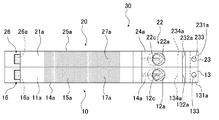
- FIG. 8A is a side view of the first and second blades 10 and 20
- FIG. 8B is a plan view of the first blade 10.
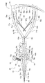
- FIG. 9 is a plan view showing a state in which the opening/closing mechanism 40 is attached to the opener body 30 and the opener body 30 is opened.
- the opening device 100A according to the second embodiment is different from the first embodiment shown in FIGS. 1 to 7 except that the first blade 10 is provided with an angle scale member (second angle scale member) 18 and an insertion depth scale 19. It has the same basic configuration as the opener 100 of the embodiment, and the operation is almost the same. Therefore, the same components as those in the first embodiment will be denoted by the same reference numerals as those in the first embodiment, and detailed description of the configuration and operation thereof will be omitted. Below, the configuration and the like different from the first embodiment will be mainly described.
- an opening device 100A includes an opening device body 30 including a first blade 10 and a second blade 20, and an opening/closing mechanism 40. .. Further, the second embodiment also includes the driving member 50 as shown in FIG. As the second blade 20, the opening/closing mechanism 40, and the driving member 50, those similar to those of the first embodiment can be used.
- the first blade 10 of the second embodiment has a pair of arm portions 11a and 11b having base end portions 14a and 14b and insertion portions 15a and 15b, and an angle adjusting portion. 12 and the engaged portion 13, and further has an angle scale member 18 and an insertion depth scale 19.
- the second blade 20 has the same configuration as the second blade 20 of the first embodiment.
- the second blade 20 may be provided with an angle scale member or an insertion depth scale. Alternatively, these may be provided on both the first and second blades 10 and 20, and it is not necessary to distinguish between the first and second blades 10 and 20. Further, the first and second blades 10 and 20 can be manufactured in the same process using the same mold, and the productivity can be improved.
- the second angle graduation member 18 includes a plate 18a, an angle graduation 18b provided on the front side of the plate 18a, an insertion hole 18c for accommodating the plate 18a in a removable manner, and an insertion hole 18c.
- the window 18d for visually recognizing the angular scale 18b of the plate 18a in the hole 18c and the needle 18e pointing to the angular scale 18b are provided.
- One end of the plate 18a is fixed to the inner side surface of the base end portion 14a of the one arm portion 11a, and extends from this inner side surface toward the other arm portion 11b in an arc shape around the support shaft 16a. It is provided.
- the insertion hole 18c is provided in the extending direction of the plate 18a, and is provided in the base end 14b of the other arm 11b so as to penetrate the base end 14b from the inner side surface to the outer side surface.
- the window portion 18d has an elliptical shape along the longitudinal direction, and is provided on the front side surface of the base end portion 14b so as to communicate with the insertion hole 18c.
- a part of the inner peripheral wall of the window portion 18d is provided so as to project inward, and a needle 18e that points to the angle scale 18b is provided.
- the plate 18a can smoothly rotate in the insertion hole 18c as the arm portions 11a and 11b of the first blade 10 rotate and move. Then, by visually observing the angle scale 18b indicated by the needle 18e from the window portion 18d, the angle ⁇ 1 between the pair of arm portions 11a and 11b can be easily and accurately grasped.
- the insertion depth scale 19 is a scale indicating the insertion depth (depth) when the insertion portions 15a and 15b of the pair of arm portions 11a and 11b of the first blade 10 are inserted into the cut portion 2 of the bone 1. As shown in FIG. 8B, the insertion depth scale 19 is provided on the front side surfaces of the insertion portions 15a and 15b along the longitudinal direction.
- the driving member 50 collectively and stably holds the first and second blades 10 and 20 to cut the cut portion 2. Can be easily inserted. Further, when the opening device main body 30 is inserted into the cut portion 2, the insertion depth scale 19 allows the insertion depth of the opening device body 30 to the cut portion 2 to be easily and clearly defined without using a separate gauge member. I can figure it out.
- the practitioner can operate the opening/closing mechanism 40 attached to the main body 30 of the opening device to open the first and second blades 10 and 20 at once.
- the first angle grading member 44 of the opening/closing mechanism 40 can grasp the angle between the operating portions 47a and 47b, that is, the angles ⁇ 1 and ⁇ 2 between the arm portions 11a, 11b, 21a and 21b.
- the angle ⁇ 1 between the arm portions 11a and 11b and the like can be grasped also by the second angle scale member 18 provided on the first blade 10.
- the practitioner uses the second angle graduation member 18 to move the pair of arms.
- the angle ⁇ 1 between the parts 11a and 11b can be grasped.
- the angle scale member 18 is housed inside the insertion hole 18d of the base end portions 14a, 14b (base end portions 24a, 24b when provided on the second blade 20). Therefore, there is no unevenness on the front and back surfaces of the first and second blades 10 and 20, and the first and second blades 10 and 20 are arranged side by side from either the front surface side or the back surface side. Can be overlaid. Therefore, the degree of freedom in the arrangement of the first and second blades 10 and 20 can be increased.
- the angle graduation (angle graduation 61) and the insertion depth graduation (graduation 26) are arranged on the surfaces intersecting with each other, so that the practitioner or the like visually recognizes them. At that time, it is necessary to change the posture and visually recognize it. Further, since the member provided with the angle scale (the connecting member 6) is detachably attached to the blade, the position of the angle scale may be displaced.
- the opening/closing mechanism 40 when the opening/closing mechanism 40 is attached to the opening device body 30, the first angle scale member 44, the second angle scale member 18, and the insertion depth scale 19 are attached.
- they are provided so as to be arranged on the same plane (front side surface).
- "Practically provided on the same plane” does not necessarily mean that they are provided on the same plane, but means that they are provided on mutually parallel planes that are visible from the same direction. .. Therefore, the practitioner or the like can easily visually recognize each of these scales from the same direction, and does not need to change his/her posture, and a smoother and quicker treatment can be performed.
- the opening device of the third embodiment will be described with reference to FIGS. 10A to 12.
- the opening device 100B of the third embodiment includes first and second opening/closing mechanisms 60 and 70 that are two opening/closing mechanisms that open and close independently.
- the opening device 100B of the third embodiment is different from the opening device of the second embodiment shown in FIGS. 8A to 9 except that it includes the first and second opening/closing mechanisms 60 and 70 instead of the opening/closing mechanism 40. It has the same basic configuration as the large device 100A. Therefore, the configuration different from that of the second embodiment will be mainly described below.
- the opening device 100B includes a opening device body 30 including a first blade 10 and a second blade 20, a first opening/closing mechanism 60, a second opening/closing mechanism 70, and a driving member 50 (FIG. 1), and.
- a first and second blades 10 and 20 as those in the second embodiment are used.
- the same thing as one embodiment can also be used.
- the same driving member 50 as in the first embodiment can be used.
- the first opening/closing mechanism 60 is used in a state of being arranged in parallel with the second opening/closing mechanism 70 so as to open/close the first and second blades 10, 20 of the opening device main body 30 collectively or individually. It is a member that can
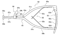
- the first opening/closing mechanism 60 includes a pair of shafts 61a and 61b, a biasing means 62, a ratchet mechanism 63, and a first angle scale member 64. It The first angle scale member may be provided on the second opening/closing mechanism 70, or may be provided on both the first and second opening/closing mechanisms 60, 70.
- the pair of shafts 61a and 61b are connected by a connecting portion 65 so as to be rotatable and movable.
- the connecting portion 65 has, for example, a pivot structure having a support shaft 65a and a bearing.
- the pair of shafts 61a, 61b are provided with handle portions 66a, 66b on the base end side via a support shaft 65a, and actuating portions 67a, 67b on the tip end side for opening/closing in conjunction with the opening/closing operation of the handle portions 66a, 66b. It is provided.
- the operating portions 67a, 67b are substantially L-shaped in a plan view, and have engaging projections 68a, 68b at their tips that project at right angles to the longitudinal direction in the width direction.
- one engagement protrusion 68a engages with one engagement recess 134a of the first blade 10
- the other engagement protrusion 68b engages with the other engagement recess 134b of the first blade 10.
- the second opening/closing mechanism 70 is used in a state of being arranged in parallel with the first opening/closing mechanism 60 so as to open/close the first and second blades 10 and 20 of the opening device main body 30 collectively or individually. It is a member that can be made.
- the second opening/closing mechanism 70 includes a pair of shafts 71a and 71b, a biasing means 72, and a ratchet mechanism 73.
- the pair of shafts 71a and 71b are rotatably and movably connected by a connecting portion 75.
- the connecting portion 75 has, for example, a pivot structure having a support shaft 75a and a bearing.
- the pair of shafts 71a, 71b are provided with handle portions 76a, 76b on the base end side via a support shaft 75a, and have operating portions 77a, 77b on the tip end side for opening/closing in conjunction with the opening/closing operation of the handle portions 76a, 76b. It is provided.
- the operating portions 77a, 77b are substantially L-shaped in a plan view, and have engagement protrusions 78a, 78b protruding at right angles in the width direction with respect to the longitudinal direction at their tips.
- one engagement protrusion 78a engages with one engagement recess 234a of the second blade 20
- the other engagement protrusion 78b engages with the other engagement recess 234b of the second blade 20.
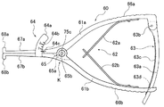
- FIG. 11A shows a state in which the first opening/closing mechanism 60 is attached to the first blade 10 inserted in the notch 2 and the second opening/closing mechanism 70 is attached to the second blade 20.
- the engagement protrusion 68a of the one actuating portion 67a of the first opening/closing mechanism 60 is engaged with the one engagement recess 134a of the first blade 10.
- the engagement protrusion 68b of the other actuating portion 67b is engaged with the other engagement recess 134b of the first blade 10.
- the engagement protrusion 78a of the one operating portion 77a of the second opening/closing mechanism 70 is engaged with the one engagement recess 234a of the second blade 20.
- the engaging protrusion 78b of the other operating portion 77b is engaged with the other engaging recess 234b of the second blade 20 (operating portions 77a, 77b, engaging protrusions 78a, 78b, and engaging recesses 234a, 234b). See FIG. 12).
- How to combine the first and second blades 10 and 20 of the dilator main body 30 and the first and second opening/closing mechanisms 60 and 70 determines whether the affected part (bone 1) to be applied is on the left or right side of the patient. Accordingly, the orientations of the first angle graduation member 64 and the second angle graduation member 18 can be taken into consideration, and can be arbitrarily selected. Therefore, the second opening/closing mechanism 70 can be attached to the first blade 10 and the first opening/closing mechanism 60 can be attached to the second blade 20.
- the first angle graduation member 64 includes a plate 64a, an angle graduation 64b, and a needle 64c.
- the ratchet mechanism 63 includes a lever member 63a provided with a plurality of ratchet teeth 63c, a support shaft 63b, and a tooth clamp portion 63d.
- the operating portions 67a and 67b can be opened at an angle of 0.5° by the closing operation of the handle portions 66a and 66b for one ratchet tooth 63c.
- the ratchet mechanism 73 also has a configuration similar to that of the ratchet mechanism 63 and can open the operating portions 77a and 77b by 0.5°.
- the pair of handle portions 66a, 66b of the first opening/closing mechanism 60 is gripped and they are rotationally moved in the directions in which they approach each other. ..
- the operating portions 67a and 67b are rotationally moved in the separating direction with the support shaft 65a as the fulcrum, and the pair of arm portions 11a and 11b of the first blade 10 are rotated in the separating direction. It can be moved and opened at a predetermined angle ( ⁇ 1).
- the pair of arm portions 21a and 21b of the second blade 20 can be opened at a predetermined angle ( ⁇ 2).
- ⁇ 2 a predetermined angle
- the first and second blades 10 and 20 can be individually opened by individually operating the first and second opening/closing mechanisms 60 and 70.
- the arm portions 11a and 11b of the first blade 10 and the arm portions 21a and 21b of the second blade 20 can be opened at different angles ⁇ 1 and ⁇ 2.
- the arm portions 11a, 11b, 21a and 21b of the first and second blades 10 and 20 are collectively and collectively the same. It can be opened at angles ⁇ 1 and ⁇ 2.
- the practitioner can freely select collective operation or individual operation according to the site of the operation, the surgical field space, and the like.
- the first and second opening/closing mechanisms 60 and 70 when removing the first and second opening/closing mechanisms 60 and 70 from the first and second blades 10 and 20, like the opening/closing mechanism 40 of the first embodiment, the first and second opening/closing mechanisms 60, 70, 70 is slid in the height direction, and the ratchet mechanisms 63 and 73 are restored. This allows them to be removed individually or collectively.
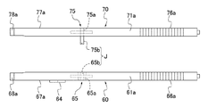
- the opening device of the fourth embodiment will be described with reference to FIGS. 13A and 13B.
- the opening device of the fourth embodiment is different from the first and second opening/closing mechanisms 60 and 70 in that an engaging mechanism J that engages these in a connectable and separable manner is provided.
- the opener 100B of the third embodiment shown in FIGS. 10A to 12 has the same basic configuration. That is, the opening device according to the fourth embodiment includes a opening device main body 30 (see FIGS. 8A to 9) including the first blade 10 and the second blade 20, opening/closing mechanisms 60 and 70, and a driving member 50. (See FIG. 1).
- the pair of shafts 61a, 61b, 71a, 71b of the first and second opening/closing mechanisms 60, 70 are rotatably connected to each other by connecting portions 65, 75 each of which includes a support shaft 65a, 75a and a bearing.
- An engaging protrusion 75b that projects toward the side opposite to the first opening/closing mechanism 60 is integrally provided on the support shaft 75a of the second opening/closing mechanism 70.
- the support shaft 65a of the first opening/closing mechanism 60 is made of a cylindrical member having a diameter larger than that of the support shaft 75a, and an engagement recess 65b for engaging the engagement protrusion 75b is provided inside the cylindrical member.
- the above-described engaging mechanism J is composed of the engaging concave portion 65b and the engaging protrusion 75b.
- the first opening/closing mechanism 60 is provided with the engaging recessed portion 65b and the second opening/closing mechanism 70 is provided with the engaging protrusion 75b.
- the present invention is not limited to this configuration, and the first opening/closing mechanism may be used.
- the mechanism 60 may be provided with an engagement protrusion, and the second opening/closing mechanism 70 may be provided with an engagement recess. The same applies to the other embodiments including the engagement mechanism J.
- the first and second opening/closing mechanisms 60 and 70 can be connected to each other by the support shafts 65a and 75a by engaging the engagement protrusion 75b with the engagement recess 65b. Therefore, the positioning when the first and second opening/closing mechanisms 60 and 70 are arranged in parallel can be performed more easily and accurately, and the attachment to the first and second blades 10 and 20 can be further improved. It can be performed efficiently and stably.
- the operation of each shaft 61a, 61b, 71a, 71b is not hindered at all and is independent of each other. It can be operated freely. In addition, the stability of the practitioner in holding and operating these is also improved. And also in the opening device of 4th Embodiment, similarly to 3rd Embodiment, by operating the 1st, 2nd opening/closing mechanism 60, 70 collectively or individually, the 1st, 2nd blades 10 and 20 are operated. It can be opened and closed collectively or individually at a desired angle. Further, by disengaging the engagement projection 75b and the engagement recess 65b from each other, the first and second opening/closing mechanisms 60 and 70 can be easily separated, and a compact storage without bulkiness or the like is possible. Become.
- the first and second opening/closing mechanisms 60, 70 are provided with the engaging mechanism J for connecting and disconnecting them, but as another different embodiment, an appropriate connection is made.
- the first and second opening/closing mechanisms 60 and 70 may be connected inseparably by a mechanism.
- this connection mechanism include a configuration in which the engagement protrusion 75b and the engagement recess 65b cannot be separated by caulking or the like. In this configuration, by connecting the engagement projection 75b and the engagement recess 65b, it is possible to save the labor of positioning the first and second opening/closing mechanisms 60 and 70 while stacking them in parallel.
- first and second opening/closing mechanisms 60 and 70 can be freely operated collectively or individually, and the first and second blades 10 and 20 can be collectively or individually operated at a desired angle. It is easy to open and close.
- the opening device of the fifth embodiment will be described with reference to FIGS. 14A to 14C.
- the opening device of the fifth embodiment is shown in FIGS. 8A to 9 except that it has an opening/closing mechanism 80 shown in FIGS. 14A to 14C instead of the opening/closing mechanism 40.
- It has the same basic configuration as the opening device 100A of the second embodiment. That is, the opening device according to the fifth embodiment includes an opening device body 30 (see FIGS. 8A to 9) including the first blade 10 and the second blade 20, an opening/closing mechanism 80, and a driving member 50 (see FIG. 1), and.
- the opening/closing mechanism 80 includes two first and second actuating shafts 81a1 and 81a2 arranged in parallel, one support shaft 81b rotatably and movably connected to the first and second actuating shafts 81a1 and 81a2, and the first and second actuating shafts 81a1 and 81a2.
- the first and second biasing means 82A and 82B and the first and second ratchet mechanisms 83A and 83B provided in twos corresponding to the operation shafts 81a1 and 81a2, and the support shaft 81b, the plate 84a, the angle.
- a first angle graduation member 84 including a graduation 84b and a needle 84c.
- the connecting portion 85 has, for example, a pivot structure having a support shaft 85a and a bearing.
- Each of the first and second actuating shafts 81a1 and 81a2 is provided with first and second handle portions 86a1 and 86a2 on the base end side via a support shaft 85a.
- First and second actuating portions 87a1 and 87a2 that open and close in conjunction with the opening and closing operations of the first and second handle portions 86a1 and 86a2 are provided on the tip end side.
- the first and second actuating portions 87a1 and 87a2 are substantially L-shaped in a plan view, and the first and second engaging projections 88a1 and 88a2 protruding in the width direction with respect to the longitudinal direction and at the same angle at the tip are the tips. It is provided in.
- the first engagement protrusion 88a1 engages with one engagement recess 134a of the first blade 10, for example.
- the second engagement protrusion 88a2 engages with one engagement recess 234a of the second blade 20, for example.
- One support shaft 81b is provided for the two first and second actuating shafts 81a1 and 81a2.
- the thickness of the support shaft 81b in the height direction is substantially the same as the combined thickness of the two operating shafts 81a1 and 81a2.
- the support shaft 81b is provided with a handle portion 86b on the base end side through a support shaft 85a, and an operating portion 87b on the tip end side for opening and closing in conjunction with the opening and closing operation of the handle portion 86b.
- the actuating portion 87b of the support shaft 81b is substantially L-shaped in a plan view, and an engaging protrusion 88b protruding at a right angle to the longitudinal direction in the width direction is provided at the tip.
- the engagement protrusion 88b engages with the other engagement recess 134b of the first blade 10 and the other engagement recess 234b of the second blade 20, for example.
- the combination of the first and second blades 10 and 20 and the opening/closing mechanism 80 depends on whether the affected part (bone 1) to be applied is on the left or right side of the patient.
- the angle graduation member 18 can be arbitrarily selected in consideration of its orientation. Therefore, the first engagement protrusion 88a1 of the first actuating shaft 81a1 engages with the one engagement recess 234a of the second blade 20, and the second engagement protrusion 88a2 of the second actuating shaft 81a2 causes the first blade 10 to move.
- the first and second blades 10 and 20 and the opening/closing mechanism 80 may be combined so as to engage with one of the engaging recesses 134a.
- first and second engagement protrusions 88a1 and 88a2 of the first and second actuating shafts 81a1 and 81a2 are engaged with either of the other engagement recesses 134b and 234b of the first and second blades 10 and 20, respectively.
- the first and second blades 10 and 20 and the opening/closing mechanism so that the engagement protrusions 88b of the support shaft 81b engage with the engagement recesses 134a and 234a of one of the first and second blades 10 and 20. 80 can also be combined.
- the first operating shaft 81a1 or the second operating shaft 81a2 is operated collectively or individually with respect to the support shaft 81b, so that the first and second blades 10, 20 of the opening device main body 30 are moved. It can be opened and closed collectively or individually at a desired angle.
- the handle portion 86b of the support shaft 81b and the first handle portion 86a1 of the first actuating shaft 81a1 are gripped, and they are rotated in directions close to each other.
- the first actuating portion 87a1 rotationally moves in the separating direction relative to the actuating portion 87b of the support shaft 81b.
- the pair of arm portions 11a and 11b of the first blade 10 can be rotationally moved in the separating direction from each other and can be opened at a predetermined angle ( ⁇ 1).
- the handle portion 86b of the support shaft 81b and the second handle portion 86a2 of the second actuating shaft 81a2 are gripped, and they are rotationally moved in the directions in which they approach each other.
- the second operating portion 87a2 is rotationally moved in the separating direction relative to the operating portion 87b of the support shaft 81b.
- the pair of arm portions 21a and 21b of the second blade 20 can be rotationally moved in the direction in which they are separated from each other and can be opened at a predetermined angle ( ⁇ 2).
- the first and second blades 10 and 20 can be individually opened by individually operating the first and second operation shafts 81a1 and 81a2 with respect to the support shaft 81b. it can. Furthermore, the arm portions 11a and 11b of the first blade 10 and the arm portions 21a and 21b of the second blade 20 can be opened at different angles ⁇ 1 and ⁇ 2.
- the first and second actuating shafts 81a1 and 81a2 are collectively operated with respect to the support shaft 81b, whereby the arm portions 11a, 11b and 21a of the first and second blades 10 and 20 are operated. , 21b can be opened collectively and at the same angles ⁇ 1 and ⁇ 2. The practitioner can freely select collective operation or individual operation according to the site of the operation, the surgical field space, and the like.
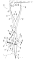
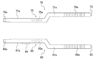
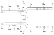
- FIGS. 15A and 15B the opening device of the sixth embodiment will be described with reference to FIGS. 15A and 15B.
- the opening device of the sixth embodiment is different from FIGS. 11A to 12 except that the shapes of the shafts 61a, 61b, 71a, 71b of the first and second opening/closing mechanisms 60, 70 are different.
- the same basic configuration as that of the opening device 100B of the third embodiment shown in FIG. 3 is provided, and the same operational effect as that of the third embodiment can be obtained. For this reason, detailed description of the configuration and the effect of the opening device of the sixth embodiment will be omitted.
- the handle portions 66a, 66b of the shafts 61a, 61b of the first opening/closing mechanism 60 and the handle portions 76a, 76b of the shafts 71a, 71b of the second opening/closing mechanism 70 are, as shown in FIG. 15B, It is bent so as to bulge in the direction away from each other. That is, each of the shafts 61a, 61b, 71a, 71b has a shape in which the handle portions 66a, 66b, 76a, 76b are offset with respect to the operating portions 67a, 67b, 77a, 77b (hereinafter, "offset handle portion"). Etc.).
- the handle portions 66a, 66b of the first opening/closing mechanism 60 and the handle portions 76a, 76b of the second opening/closing mechanism 70 are arranged. They are arranged apart from each other at a predetermined interval.
- the first and second blades 10 and 20 are operated at a desired angle by operating the first and second opening/closing mechanisms 60 and 70 collectively or individually. Can be opened and closed collectively or individually. Further, in the sixth embodiment, the handle portions 66a, 66b, 76a, 76b are offset. With this configuration, when the first and second blades 10 and 20 are opened by the first and second opening/closing mechanisms 60 and 70 to open the affected area (bone 1), the space of the surgical field on a straight line from the affected area and Therefore, it is possible to obtain a special effect that it is easy to secure the field of view.
- the opening device of the seventh embodiment is different from the first and second opening/closing mechanisms 60 and 70 in that an engaging mechanism J that engages these in a separable manner is provided.
- the first and second opening/closing mechanisms 60 and 70 are provided with the same basic configuration as the large opening device of the sixth embodiment.
- the engaging mechanism J of the seventh embodiment is similar to the fourth embodiment in that the engaging protrusion 75b provided on the support shaft 75a of the second opening/closing mechanism 70 so as to project therefrom and the cylindrical member of the first opening/closing mechanism 60. It is composed of an engaging recess 65b provided inside a manufactured support shaft 65a.
- the first and second opening/closing mechanisms 60 and 70 may be inseparably connected by an appropriate connection mechanism.
- the engagement between the engagement projection 75b and the engagement recess 65b enables positioning when the first and second opening/closing mechanisms 60 and 70 are arranged in parallel. It can be performed easily and accurately. Therefore, the attachment to the first and second blades 10 and 20 can be performed more efficiently and reliably, and the stability of the practitioner during their operation is also improved. Further, by releasing the engagement between the engagement projection 75b and the engagement recess 65b, the first and second opening/closing mechanisms 60 and 70 can be easily separated, and compact storage or the like can be performed.
- the first and second blades 10 and 20 can be opened or closed collectively or individually at a desired angle. Further, since the handle portions 66a, 66b, 76a, 76b are offset, it becomes easy to secure a space in the surgical field on a straight line from the affected area and a field of view.
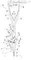
- the opening device of the eighth embodiment will be described with reference to FIGS. 17A and 17B.
- the opening device of the eighth embodiment is similar to the third embodiment shown in FIGS. 10A to 12 and the first and second opening/closing mechanisms 60 and 70 shown in FIGS. 15A and 15B. It is a modification of 6th Embodiment.
- the first opening/closing mechanism 60 having straight type handle portions 66a, 66b which are not offset as in the third embodiment and the offset type handle portions 76a, 76b as in the sixth embodiment are provided.
- the second opening/closing mechanism 70 is included.
- the handle parts 66a, 66b of the first opening/closing mechanism 60 are different from the handle parts 76a of the second opening/closing mechanism 70.
- 76b are spaced apart via a predetermined interval. This predetermined interval is about half the interval between the handle portions 66a, 66b, 76a, 76b of the sixth embodiment.
- the first opening/closing mechanism 60 and the second opening/closing mechanism 70 are not limited to the above-mentioned configuration, and the first opening/closing mechanism 60 has offset type handle portions 66a and 66b similar to those in the sixth embodiment.
- the second opening/closing mechanism 70 may have the straight type handle portions 76a and 76b similar to those in the third embodiment.
- the first and second blades 10 and 20 can be operated at desired angles by operating the first and second opening/closing mechanisms 60 and 70 collectively or individually. Can be opened and closed collectively or individually. Further, since the handle portions 76a and 76b of the second opening/closing mechanism 70 are offset from each other, it is easy to secure the space of the surgical field on a straight line from the affected area and the field of view, and the bulging in the alignment direction is further reduced. be able to.
- the opening device of the ninth embodiment is different from the first and second opening/closing mechanisms 60, 70 in that an engaging mechanism J for connecting and disconnecting them is provided.
- the first and second opening/closing mechanisms 60 and 70 are provided with the same basic configuration as the opening device of the eighth embodiment.
- the engaging mechanism J of the ninth embodiment is similar to the fourth embodiment in that the engaging projection 75b provided so as to project from the support shaft 75a of the second opening/closing mechanism 70 and the support shaft of the first opening/closing mechanism 60.
- the engaging recess 65b is provided inside the cylindrical member 65a.
- the first and second opening/closing mechanisms 60 and 70 may be inseparably connected by an appropriate connection mechanism.
- the first and second blades 10 and 20 can be operated at a desired angle by operating the first and second opening/closing mechanisms 60 and 70 collectively or individually. Can be opened and closed collectively or individually. Further, since the handle portions 76a and 76b of the second opening/closing mechanism 70 are offset from each other, it is easy to secure the space of the surgical field on a straight line from the affected area and the field of view, and the bulging in the alignment direction is further reduced. be able to. Furthermore, by providing the engagement mechanism J, the positioning when the first and second opening/closing mechanisms 60 and 70 are arranged in parallel can be easily and accurately performed, and accidental dropout can be suppressed and operation can be performed. Time stability and transportability can be improved.
- the opening device of the tenth embodiment will be described with reference to FIGS. 19A and 19B.
- the opening device of the tenth embodiment is different from the sixth embodiment in which the first and second opening/closing mechanisms 60 and 70 are shown in FIGS. 15A and 15B, except that a positioning portion K is provided. It has the same basic configuration as the large opener. Therefore, the configuration of the positioning portion K different from that of the sixth embodiment will be mainly described below.
- the positioning portion K includes a positioning protrusion 75c formed by projecting the support shaft 75a of the second opening/closing mechanism 70 to the side facing the first opening/closing mechanism 60, and a support shaft 65a made of a cylindrical member of the first opening/closing mechanism 60. And a positioning recessed portion 65c provided inside.
- the positioning protrusion 75c is a protrusion that is shorter and smaller than the engaging protrusion 75b of the ninth embodiment and the like. Therefore, when the first and second opening/closing mechanisms 60 and 70 are overlapped with each other, the positioning protrusion 75c easily engages with the positioning recessed portion 65c, but the first and second opening/closing mechanisms 60 and 70 can be moved in the longitudinal direction and the axial direction. The engagement can be easily released by sliding it slightly.
- the first and second blades 10 and 20 can be operated at a desired angle by operating the first and second opening/closing mechanisms 60 and 70 collectively or individually. Can be opened and closed collectively or individually. Further, since the handle portions 66a, 66b, 76a, 76b of the first and second opening/closing mechanisms 60, 70 are offset, it is easy to secure a space in the operative field on a straight line from the affected area and a field of view. it can. Further, by providing the positioning portion K, positioning when the first and second opening/closing mechanisms 60 and 70 are arranged in parallel can be performed easily and accurately, and the first and second opening/closing mechanisms 60 and 70 can be positioned.
- the handle portions 66a, 66b, 76a, 76b are offset types, but the present invention is not limited to this, and it is also possible to use all straight types or to combine offset types and straight types. ..
- the opening devices 100, 100A, 100B, etc. of the above-described respective embodiments include the opening device main body 30 having the first blade 10 and the second blade 20 that can be arranged in parallel with the first blade 10, the first blade 10 and the first blade 10.
- the opening/closing mechanism 40,60,70,80 which opens/closes the 2 blade 20 is provided.
- the first blade 10 and the second blade 20 have a pair of arm portions 11a, 11b, 21a, 21b whose distal end portions are connected to each other so as to be rotatable and movable in a separation direction and a proximity direction, and a pair of arm portions 11a, 11b, 21a. , 21b, and an angle adjusting unit 12 for adjusting the angle between the two.
- the opening/closing mechanisms 40, 60, 70, 80 include a plurality of shafts 41a, 41b, 61a, 61b, 71a, 71b, 81a1, 81a2, 81b rotatably connected by support shafts 45a, 65a, 75a, 85a.
- Prepare Each of the shafts 41a and the like is operated by interlocking the handle portions 46a, 46b, 66a, 66b, 76a, 76b, 86a1, 86a2, 86b on one end side with the support shaft 45a and the like and the handle portion 46a and the like on the other end side.
- the operating portions 47a, 47b, 67a, 67b, 77a, 77b, 87a1, 87a2, 87b are configured to operate.
- the actuating portion 47a or the like of each shaft 41a or the like includes the base end portions 14a and 14b of one or the other arm portions 11a and 11b of the first blade 10 and/or the one or the other arm portion 21a of the second blade 20.
- Engagement portions engagement protrusions 48a, 48b, 68a, 68b, 78a, 78b, 88a1, 88a2, 88b
- the engagement between the base end portion 14a and the like and the engagement portion allows the practitioner to grasp the handle portion 46a and the like and press the handle portion 46a and the like in the approaching direction. 20 can be opened. Therefore, it is possible to more reliably and easily open the cut portion 2 to a desired size. Therefore, it is possible to open and close the plurality of blades 10 and 20 easily and smoothly collectively or individually, and it is possible to provide the openers 100 and 100A having excellent operability and durability and a simple structure.
- the opening devices 100 and 100A of the first and second embodiments are the opening device body 30 having the first blade 10 and the second blade 20 that can be arranged in parallel with the first blade 10, the first blade 10 and An opening/closing mechanism 40 for opening/closing the second blade 20.
- the first blade 10 and the second blade 20 have a pair of arm portions 11a, 11b, 21a, 21b whose distal ends are rotatably movable in the separating direction and the approaching direction, and a pair of arm portions 11a, 11b, 21a. , 21b, and an angle adjusting unit 12 for adjusting the angle between the two.
- the opening/closing mechanism 40 includes a pair of shafts 41a and 41b rotatably connected by a support shaft 45a.
- Each of the shafts 41a and 41b is configured to have handle portions 46a and 46b on one end side via a support shaft 45a and actuating portions 47a and 47b that operate in conjunction with the handle portions 46a and 46b on the other end side. ..
- the operating portion 47a of the one shaft 41a has one engaging portion (engaging protrusion 48a) that engages with the base end portions 14a and 24a of the arm portions 11a and 21a of the first blade 10 and the second blade 20. Is provided.
- the operating portion 47b of the other shaft 41b has the other engaging portion (engaging protrusion 48b) that engages with the base end portions 14b and 24b of the other arm portions 11b and 21b of the first blade 10 and the second blade 20. Is provided.
- the practitioner only grips the handle portions 46a, 46b and presses the handle portions 46a, 46b in the proximity direction by the engagement between the base end portions 14a, 14b, 24a, 24b and the engaging portions.
- the second blades 10 and 20 can be collectively opened. Further, the angles ⁇ 1, ⁇ 2 between the pair of arm portions 11a, 11b, 21a, 21b can be easily adjusted to the same angle collectively. Therefore, it is possible to more reliably and easily open the cut portion 2 to a desired size. Therefore, it is possible to easily and smoothly open and close the plurality of blades 10 and 20 collectively or individually, and it is possible to provide the openers 100 and 100A having excellent operability and durability and a simple configuration.
- one opening/closing mechanism 80 is provided, and the opening/closing mechanism 80 is arranged as a plurality of shafts so that one supporting shaft 81b is rotatably connected to the supporting shaft 81b by a support shaft 85a and is arranged in parallel. And two actuating shafts 81a1 and 81a2.
- the support shaft 81b and the two actuating shafts 81a1 and 81a2 operate by interlocking with the handle portions 86b, 86a1 and 86a2 on one end side and the handle portion 86b and the like on the other end side via the support shaft 85a.
- the engaging portion provided on the operating portion 87b of the support shaft 81b engages with the base end portion of one arm portion of the first blade 10 and the second blade 20.
- the engaging portion provided on the operating portion of one of the two operating shafts 81a1 and 81a2 engages with the base end portion of the other arm portion of the first blade 10.
- the engaging portion provided on the operating portion of the other operating shaft engages with the base end portion of the other arm portion of the second blade 20.
- each of the opening/closing mechanisms 60, 70 includes a pair of shafts 61a, 61b, 71a, 71b rotatably connected by support shafts 65a, 75a.
- the engaging portions provided on the operating portions of the pair of shafts of the one opening/closing mechanism engage with the base end portions 14a and 14b of the pair of arm portions 11a and 11b of the first blade 10.
- the engaging portions provided on the operating portions of the pair of shafts of the other opening/closing mechanism engage with the base end portions 24a and 24b of the pair of arm portions 21a and 21b of the second blade 20.
- first and second opening/closing mechanisms 60 and 70 can be collectively or individually freely operated to open and close the first and second blades 10 and 20 collectively or individually. Further, the angles ⁇ 1 and ⁇ 2 of the first and second blades 10 and 20 can be easily and arbitrarily adjusted.
- the two opening/closing mechanisms 60 and 70 may be provided with an engaging mechanism J that is separably engaged with at least the support shafts 65a and 75a.
- the two opening/closing mechanisms 60 and 70 may be configured to include a connection mechanism that non-separably connects at least the support shafts 65a and 75a. According to these configurations, positioning when the first and second opening/closing mechanisms 60 and 70 are arranged in parallel can be performed more easily and accurately, and the first and second blades 10 and 20 can be positioned. The mounting can also be performed more efficiently and stably.
- the positioning unit K for arranging the two opening/closing mechanisms 60 and 70 in parallel is provided. With this configuration, it is possible to easily and accurately perform positioning when the first and second opening/closing mechanisms 60 and 70 are arranged in parallel and stacked. In addition, the first and second opening/closing mechanisms 60 and 70 can be easily separated to allow compact storage and the like.
- the handle portion of at least one opening/closing mechanism is offset with respect to the operating portion.
- the engaging portion extends from the tip of the operating portion 47a, 47b, 67a, 67b, 77a, 77b, 87a1, 87a2, 87b toward the direction in which the arm portions 11a, 11b, 21a, 21b open. It has engaging projections 48a, 48b, 68a, 68b, 78a, 78b, 88a1, 88a2, 88b which project.
- the engagement protrusions 48a, 48b, 68a, 68b, 78a, 78b, Engagement recesses 134a, 134b, 234a, 234b with which 88a1, 88a2, 88b are engaged are provided.
- the gripping force applied to the handle portions 46a, 46b, 66a, 66b, 76a, 76b, 86a1, 86a2, 86b effectively acts on the opening device main body 30 and excessive labor is required.
- the opening operation of the opening device main body 30 can be easily performed without doing so.
- the angle adjusting portions 12 and 22 of the above-described embodiments include screw holes 12a and 22a provided in one arm portion 11a and 21a penetrating the arm portions 11a and 21a, and the screw holes 12a and 22a. It has push screws 12b and 22b that are fastened and have their tips abutted against the inner side surfaces of the other arm portions 11b and 21b. Even when the opening/closing mechanism 40 is removed, the angle adjusting portions 12 and 22 can maintain the open state of the arm portions 11a, 11b, 21a and 21b at the desired angles ⁇ 1 and ⁇ 2.
- the first blade 10 (and/or the second blade 20) is provided with the angle scale member 18 indicating the angle between the pair of arm portions 11a and 11b. ..
- the angle graduation member 18 has one end fixed to the inner side surface of the one arm 11a and extends toward the other arm 11b, a plate 18a provided on the plate 18a, and the other graduation 18b.
- An insertion hole 18c that is provided in the arm portion 11b and into which the plate 18a is freely inserted and removed, a window portion 18d for visually recognizing the angle scale 18b, and the angle scale 18b according to the angle between the pair of arm portions 11a and 11b.
- a needle 18e is provided in the arm portion 11b and into which the plate 18a is freely inserted and removed.
- the angle ⁇ 1 of the pair of arm portions 11a and 11b can be easily and clearly grasped, and as a result, the enlarged state of the cut portion 2 can be clearly grasped. Further, the positional deviation of the angle graduation member 18 is suppressed, and the angle ⁇ 1 can always be measured accurately. Further, since the angle graduation member 18 does not project to the front side surface or the back side surface of the first blade 10, the second blade 20 can be stably stacked, and as a result, excellent operability and the like can be maintained.
- the bone 1 is provided on the outer surface (front side surface) of the first blade 10 (and/or the second blade 20) that is parallel to the surface of the angle scale member 18 on which the angle scale 18b is provided.
- a scale (insertion depth scale 19) indicating the depth of insertion into the cut 2 is provided. Accordingly, the insertion depth of the dilator main body 30 into the cutout portion 2 can be grasped easily and more accurately without using a separate gauge.
- the opening/closing mechanisms 40, 60, 70, 80 are provided with angle scale members 44, 64, which indicate angles between the operating portions 47a, 47b, 67a, 67b, 77a, 77b, 87a1, 87b facing each other.
- 84 is provided so as to be disposed substantially in the same plane as the angle graduation member 18 of the opening device body 30.
- the driving member 50 for driving the first blade 10 and the second blade 20 into the notch 2 provided in the bone 1 is provided.
- the driving member 50 has a grip portion 51 to be grasped by a practitioner, and an accommodating portion 52 that collectively accommodates the base end portions 14a, 14b, 24a, 24b of the first blade 10 and the second blade 20. ing. With this configuration, the first and second blades 10 and 20 can be stably held by the driving member 50, and the driving operation into the cut portion 2 can be efficiently performed.
Landscapes
- Health & Medical Sciences (AREA)
- Life Sciences & Earth Sciences (AREA)
- Orthopedic Medicine & Surgery (AREA)
- Surgery (AREA)
- Biomedical Technology (AREA)
- Engineering & Computer Science (AREA)
- Nuclear Medicine, Radiotherapy & Molecular Imaging (AREA)
- Heart & Thoracic Surgery (AREA)
- Medical Informatics (AREA)
- Molecular Biology (AREA)
- Animal Behavior & Ethology (AREA)
- General Health & Medical Sciences (AREA)
- Public Health (AREA)
- Veterinary Medicine (AREA)
- Surgical Instruments (AREA)
Abstract
複数のブレードの開閉を一括して又は個別に容易かつ円滑に行うことができ、操作性、耐久性に優れ、簡易な構成の開大器を提供する。 開大器100を、第1ブレード(10)及び第2ブレード(20)を有する開大器本体(30)と、打込部材(50)とを備えて構成する。第1、第2ブレード(10,20)は、一対のアーム部(11a,11b,21a,21b)と、角度調整部(12,22)と、を備える。開閉機構(40)は、一対のシャフト(41a,41b)を備え、各シャフト(41a,41b)は、ハンドル部(46a,46b)と作動部(47a,47b)を有し、各作動部(47a,47b)には、第1ブレード(10)及び第2ブレード(20)の基端部(14a,24a)の係合凹部(134a,134b,234a,234b)に係合する一対の係合突起(48a,48b)が設けられている。
Description
本開示は、開大器に関する。
変形性膝関節症の治療として、内反型の変形(いわゆるO脚)を矯正するための高位脛骨骨切り術(High Tibial Osteotomy:HTO)、外反型の変形(いわゆるX脚)を矯正するための遠位大腿骨骨切り術(Distal Femoral Osteotomy:DFO)等が行われている。
このような骨切り術のため、変形した大腿骨や脛骨に形成した切込み部(骨切り部)に挿入されて、この切込み部を拡大して人工骨等の移植物を挿入するためのスペースを形成する技術が開発されている(例えば、特許文献1~6及び非特許文献1参照)。
特許文献1には、先端が互いに回転可能に連結された一対の揺動部材(アーム部)からなる1つのブレードと、このブレードを開閉させる1対の開閉部材と、を備えた開大器に係る発明が開示されている。
特許文献2には、先端同士が回転可能に連結された長尺な一対の揺動部材をそれぞれ有し着脱可能に組み合わせられた2つのブレードと、これら2つのブレードを開閉させる2つの開閉機構と、を備え、一方のブレードの一対の揺動部材に、他方のブレードと組み合わせられたときに、該他方の一対の揺動部材の凹部に係合する突起(係合部)が設けられた開大器が開示されている。
特許文献3~特許文献6には、先端同士が回転可能に連結された長尺な2つの揺動部材をそれぞれ有する2つのブレードと、これら2つのブレードを一括して開閉する開閉機構と、を備えた開大器が開示されている。
上述した特許文献1に記載の技術では、一対の揺動部材によって拡大された切込み部に、この一対の揺動部材を挿入した状態で人工骨を挿入するため、揺動部材が人工骨の挿入の妨げとなるおそれがある。
これに対して、特許文献2に記載の発明では、切込み部に挿入された2つのブレードで切込み部を拡大した後に、突起と凹部の係合を解除して、他方のブレードを切込みから抜去し、この抜去によって空いた空間に、人工骨を挿入している。その後、一方のブレードを切込みから取り出し、この取り出しによって空いた空間に、別の人工骨を挿入している。これにより、切込み部内への人工骨の挿入操作を容易に行うことができる。
しかしながら、特許文献2に記載の発明では、他方のブレードを閉じ、さらに一方及び他方のブレード同士を、切込み部への挿入方向と交差する方向に互いに離間させて、突起と凹部の係合を解除してからでないと、他方のブレードを抜去することができない。したがって、抜去作業を迅速に行なえず、その結果、人工骨の留置に時間がかかってしまう。また、両ブレードの矯正角(開大角)が小さい場合には、他方のブレードを閉じても、突起と凹部の係合が完全には外れず、突起と凹部が干渉することがあり、この場合、両ブレードの分離が困難である。
また、この特許文献2に記載の開大器では、各ブレードの回転角度を調整する際に、一方のブレードに対し操作力を付与して、当該一方のブレードの回転角度を調整することにより、これに係合する他方のブレードの回転角度もそれに連動して調整されるよう構成されている。しかしながら、両ブレードは、突起と凹部の係合だけで組立状態が維持されているため、分解され易い。両ブレードが不測に分解された場合、他方のブレードに、一方のブレードからの操作力が十分に伝わらず、両ブレードの回転角度を同じ角度に安定して調整することが困難である。また、突起と凹部との係合部に多大な負荷がかかり、開大器の耐久性等に影響するおそれもある。
これに対して、特許文献3~6に記載の発明では、2つのブレードを連結部材で連結して、1つの開閉機構で一括して開閉するため、ブレードの一箇所に集中して負荷がかかるのを抑制することができる。
しかしながら、特許文献3~6に記載の発明では、長尺なドライバや六角レンチを用いて、ブレードから遠い位置でドライバを回転させて開閉機構を操作するため、開閉機構への力の伝達が良好に行えないおそれや、ドライバや六角レンチと開閉機構との接続部に過大な負荷がかかり、これらの耐久性に影響するおそれがある。一方の揺動部材同士を連結する連結部材をプラスチックハンマー等で打ち付けて切込みへ挿入するため、バランスよく打ち付け力を作用させることが困難である。また、特許文献3、5及び6に記載の発明は、2つのブレードを連動して開大させるため、非特許文献1にあるような、骨切り部の前方と後方の開大角度を別々に調整するような症例には適していないという問題もある。特許文献4に記載の発明では、開大器の開閉にギアを組み合わせた複雑な操作機構とドライバが必要で、部品点数も多いという問題もある。
日本Knee Osteotomy フォーラム編著「ゼロから始める!Knee Osteotomyアップデート」株式会社全日本病院出版会、2018年5月25日、p.191~196
本開示は、上記の事情に鑑みて為されたもので、複数のブレードの開閉を一括して又は個別に容易かつ円滑に行うことができ、操作性、耐久性に優れ、簡易な構成の開大器を提供することを可能とするものである。
上記の目的を達成するため、本開示に係る開大器は、第1ブレード及び前記第1ブレードと並列に配置可能な第2ブレードを有する開大器本体と、前記第1ブレード及び前記第2ブレードを開閉する開閉機構と、を備え、前記第1ブレード及び前記第2ブレードは、離間方向及び近接方向に回転移動自在に先端部が互いに連結された一対のアーム部と、一対の前記アーム部間の角度を調整する角度調整部と、を備え、前記開閉機構は、支軸によって回動自在に連結された複数のシャフトを備え、各シャフトは、前記支軸を介して一端側にハンドル部を、他端側に前記ハンドル部に連動して作動する作動部を有して構成され、各シャフトの前記作動部には、前記第1ブレードの一方若しくは他方の前記アーム部の基端部、及び/又は前記第2ブレードの一方若しくは他方の前記アーム部の基端部に係合する係合部が設けられていることを特徴とする。
本開示によれば、複数のブレードの開閉を一括して又は個別に容易かつ円滑に行うことができ、操作性、耐久性に優れ、簡易な構成の開大器を提供することができる。
(第1実施形態)
以下、本開示の第1実施形態に係る開大器を、図面を参照しながら説明する。図1は、第1実施形態に係る開大器100の構成部材の平面図である。この図1に示すように、第1実施形態に係る開大器100は、第1ブレード10及び第2ブレード20を有する開大器本体30と、第1ブレード10及び第2ブレード20を開閉する開閉機構(開大ハンドル)40と、を備えて構成される。さらに第1実施形態に係る開大器100は、第1ブレード10及び第2ブレード20を骨1に形成された切込み部2(図3A等参照)に打ち込むための打込部材(打込みハンドル)50を備えている。
以下、本開示の第1実施形態に係る開大器を、図面を参照しながら説明する。図1は、第1実施形態に係る開大器100の構成部材の平面図である。この図1に示すように、第1実施形態に係る開大器100は、第1ブレード10及び第2ブレード20を有する開大器本体30と、第1ブレード10及び第2ブレード20を開閉する開閉機構(開大ハンドル)40と、を備えて構成される。さらに第1実施形態に係る開大器100は、第1ブレード10及び第2ブレード20を骨1に形成された切込み部2(図3A等参照)に打ち込むための打込部材(打込みハンドル)50を備えている。
本実施形態に係る開大器100は、例えば、高位脛骨骨切り術(HTO)等の骨1の手術に用いられる。開大器100は、開大器本体30の第1ブレード10と第2ブレード20が並列に重ねられた状態(図2A参照)で切込み部2に挿入され、この切込み部2を拡大して人工骨等の移植物を挿入するためのスペースを形成するための器具である。
なお、本明細書では、上述したように第1、第2ブレード10,20を有する開大器本体30と、開閉機構40とを備え、必要に応じて打込部材50とを備えた構成を「開大器」としているが、このような分類に限定されるものではない。例えば、開大器本体30を「開大器」とし、この「開大器」と、開閉機構40と、必要に応じて打込部材50とを備えた構成を「開大器セット」と分類することもできる。
また、本明細書では、説明を容易とするために、切込み部2に挿入する側を「先端」といい、その反対側であって、開大器100を操作する医師等の施術者の手元側を「基端」という。また、開大器本体30が延びる方向(図2Bに示す中心線Oに平行な方向)を「長手方向」といい、開く方向を「幅方向」という。「長手方向」及び「幅方向」に直交する方向(図2Aに示す支軸16a,26aの軸線I方向)を「高さ方向」又は「並び方向」という。また、一対の各部材の側面であって、外に向いた側面を「外側面」といい、対向側(内方)に向いた側面を「内側面」という。また、図1の平面図において、紙面手前側の面を「表側面」といい、紙面奥側の面を「裏側面」という。
図1及び図2Aの側面図並びに図2Bの断面図に示すように、第1ブレード10は、一対のアーム部11a,11bを備えている。この一対のアーム部11a,11bは、開閉機構40及び打込部材50が取り付けられる基端部14a,14bと、骨1の切込み部2に挿入される挿入部15a,15bと、を有している。基端部14a,14bには、角度調整部12と、被係合部13とが設けられている。
一対のアーム部11a,11bは、先端が連結部16によって回転移動自在に連結されている。連結部16は、本実施形態では、ピン状の支軸16aと、この支軸16aを回転移動自在に支持する軸受けとを有して構成され、いわゆるピボット構造をなしている。この構成により、支軸16aを回転軸として、一対のアーム部11a,11bが互いの離間方向及び近接方向に回転移動自在となっている。なお、連結部16がピボット構造に限定されるものではなく、公知の何れの構成としてもよい。
一対のアーム部11a,11bは、長尺な金属部材からなり、図2Aに「t」で示される高さ方向の厚みは、先端から基端まで同一寸法となっている。この構成により、アーム部11a,11bに、打込みや開操作等に対する優れた強度を持たせることができる。また、第1ブレード10と第2ブレード20とを、軸線I方向(高さ方向)において並列に重ねて配置できる。
これに対して、図2Bに「w」で示されるアーム部11a,11bの幅寸法は、基端部14a,14bが挿入部15a,15bよりも広くなっている。これにより、基端部14a,14bに、打ち込みや開操作に耐え得る適度な強度を持たせている。また、挿入部15a,15bは、幅寸法が基端部14a,14b側から先端方向に向かって次第に狭くなっており、先細り形状(楔形)を呈している。このような先細り形状とすることで、挿入部15a,15bを切込み部2に容易に挿入可能となっている。
また、閉じた状態でのアーム部11a,11bの互いの外側面間の角度(以下、単に「アーム部11a,11b間の角度」などという。)は5°となっている。つまり、アーム部11a,11bの角度θ1の初期値(最小値)は5°となる。第2ブレード20のアーム部21a,21b間の角度θ2も同様である。なお、角度θ1,θ2の最小値が5°に限定されるものではない。本実施形態の開大器100を適用する手術の種類や手術部位、矯正角度、移植物の大きさ等に応じて、アーム部11a,11b,21a,21bの傾斜角度を適宜変更することで、角度θ1,θ2の最小値を任意に設定できる。
角度調整部12は、連結部16を介して開閉する一対のアーム部11a,11b間の角度θ1を調整し、かつ調整後の角度θ1を保持する部材である。角度調整部12は、一方のアーム部11aの基端部14aに設けられたネジ孔12aと、このネジ孔12aに締結される押しネジ12bと、を有して構成される。ネジ孔12aは、基端部14aの外側面から内側面まで貫通して設けられている。
押しネジ12bをネジ孔12aから外すか、又は先端がネジ孔12aから内面側に突出しないように配置した状態では、図2Bに示すように、一対のアーム部11a,11bを閉じることができる。これに対して、一対のアーム部11a,11bを開いた状態で、押しネジ12bを締結方向(ネジ孔12aに挿入する方向)に回転させて、押しネジ12bの先端をネジ孔12aから突出させ、他方のアーム部11bの内側面に突き当てることで、一対のアーム部11a,11bの開状態を保持し、不測の閉じ動作を阻止できる。また、押しネジ12bのネジ孔12aへの挿入量を調整することで、一対のアーム部11a,11b間の角度θ1を調整することもできる。
また、押しネジ12bの先端は半球形を呈している。さらに、この押しネジ12bの先端が接触する他方のアーム部11bの内側面に、当該押しネジ12bの先端を収容する凹溝12cが長手方向に沿って設けられている。この構成により、一対のアーム部11a,11bの傾斜角度が相対的に変化しても、その先端を他方のアーム部11bの内側面に確実に接触できるとともに、押しネジ12bによる他方のアーム部11bの支持安定性を高めることができる。
また、アーム部11a,11bの各々の外側面には、滑り止め部17a,17bが設けられている。滑り止め部17a,17bは、切込み部2への挿入方向とは交差して設けられた複数の溝部から構成されている。この滑り止め部17a,17bが骨1の内部組織等に食い込むことで、切込み部2に挿入された第1ブレード10の不測の脱落や戻り等を抑制できる。
被係合部13は、図2A、図2Bに示すように、一対の係合突起131a,131bと、一対の係合凹溝132a,132bと、1つのボール受部133と、一対の係合凹部134a,134bと、を有して構成される。
一対の係合突起131a,131bは、基端部14a,14bの基端側を幅方向に突出して設けられている。一対の係合凹溝132a,132bは、平面視矩形であり、一対の係合突起131a,131bの外側面を軸線Iに平行に凹設してなる。ボール受部133は、一方の係合突起131aの外側面を半球形に凹設してなる。
一対の係合凹部134a,134bは、図2Bに示すように、アーム部11a,11bを閉じたときに、平面視略T字形(若しくは略矢印形)となるように、基端部14a,14bの内側面を凹設してなる。この形状により、係合凹部134a,134bに係合した後述の開閉機構40の係合突起48a,48bの不測の抜けを合理的に防止できる。
一対の係合突起131a,131bは、後述する打込部材50の収容凹部53に収容される。一対の係合凹溝132a,132bには、打込部材50の係合突条55a,55bが係合する。ボール受部133には、打込部材50の一方のボールプランジャ56aが係合する。係合凹部134a,134bには、後述する開閉機構40の係合突起48a,48bが主に係合するが、打込部材50の係合突起54も係合する。
第2ブレード20は、第1ブレード10の押しネジ12bよりも長尺な押しネジ22bを用いていること以外は、第1ブレード10と同じ基本構成を備えている。また、押しネジ12b以外の構成部材の形状や寸法も、第1ブレード10のそれらと同じ形状や寸法となっている。しかしながら、押しネジ12bと押しネジ22bとに同じものを用いてもよく、第1、第2ブレード10,20の区別をなくして、製作工程等をより簡略化できる。
このように、第1ブレード10と第2ブレード20とが同一の構成を備えることで、これらを同一の型等を用いて同一の工程で製作でき、生産性等を向上できる。以下では、第2ブレード20の構成部材を簡単に説明し、詳細な説明は省略する。
第2ブレード20は、図1及び図7に示すように、基端部24a,24bと、挿入部25a,25bと、を有する一対のアーム部21a,21bを備え、基端部24a,24bには、角度調整部22と、被係合部23とが設けられている。
一対のアーム部21a,21bは、支軸26aと軸受けを有するピボット構造の連結部26によって回転移動自在に先端が連結されている。一対のアーム部21a,21bの高さ方向の厚みは、先端から基端まで同一寸法であり、幅方向の厚みは、基端部24a,24bが挿入部25a,25bよりも厚い。挿入部25a,25bは、基端部24b側から先端方向に向かって次第に薄く形成され、先細り形状(楔形)を呈している。一対のアーム部21a,21bの両外側面には、複数の溝部からなる滑り止め部27a,27bが設けられている。
角度調整部22は、一対のアーム部21a,21b間の角度θ2を調整する部材であり、一方のアーム部21aの基端部24aに設けられたネジ孔22aと、押しネジ22bと、凹溝22cと、から構成される。前述したように、押しネジ22bは、押しネジ12bよりも長尺である。そのため、図3Aに示すように、第1ブレード10と第2ブレード20とを並列に重ねて配置したときに、押しネジ12b,22bの頭部12d,22dが干渉することなく、互いにズレて配置され、押しネジ12b,22bを各々容易に回転操作できる。
なお、第1ブレード10と第2ブレード20とを、押しネジ12b,22bが互いに異なる方向に突出するように重ねることもできる。この場合、施術者は対向する2方向から押しネジ12b,22bを回転操作できる。第1、第2ブレード10,20は、一対のアーム部11a,11b,21a,21bが中心線Oを介して線対称に形成されている。このため、手術する部位や、施術者の操作のし易さ等に応じて、角度調整部12,22が同じ向きになる姿勢、異なる向きになる姿勢の何れの姿勢でも重ねることができる。
被係合部23は、一対の係合突起231a,231bと、一対の係合凹溝232a,232bと、1つのボール受部233と、一対の係合凹部234a,234bと、を有して構成される。
開閉機構40は、開大器本体30の第1、第2ブレード10,20を一括で開閉させる部材である。開閉機構40は、一対のシャフト41a,41bと、付勢手段42と、ラチェット機構43と、角度目盛部材(第1の角度目盛部材)44と、を備えて構成される。一対のシャフト41a,41bは、連結部45によって回転移動自在に連結されている。連結部45は、例えば支軸45aと軸受けを有するピボット構造である。一対のシャフト41a,41bは、支軸45aを介して基端側にハンドル部46a,46bが設けられ、先端側にハンドル部46a,46bの開閉動作に連動して開閉する作動部47a,47bが設けられている。
作動部47a,47bは、平面視略L字形であり、長手方向に対して幅方向に直角に突出する係合突起48a,48bが先端に設けられている。一方の係合突起48aは、第1、第2ブレード10,20の一方の係合凹部134a,234aに係合し、他方の係合突起48bは、第1、第2ブレード10,20の他方の係合凹部134b,234bに係合する。
付勢手段42は、一対のハンドル部46a,46bを、互いに離間する方向に付勢する部材である。この付勢手段42は、例えば、一対の板バネ42a,42bからなる。この付勢手段42によってハンドル部46a,46bが互いに離間する方向に付勢された状態では、図1に示すように、作動部47a,47bは閉じている。
これに対して、一対のハンドル部46a,46bを把持し、付勢手段42の付勢力に抗して、これらを互いに近接する方向に押圧すると、支軸45aを支点として作動部47a,47bが互いに離間する方向に回転移動し、作動部47a,47bが開く(図5参照)。
ラチェット機構43は、ハンドル部46a,46bの基端側に設けられ、ハンドル部46a,46bの開閉動作(つまり作動部47a,47bの開閉動作)を制御する。このラチェット機構43は、複数のラチェット歯43cが設けられたレバー部材43aと、このレバー部材43aの一端を一方のハンドル部46aの基端に回転移動自在に軸支する支軸43bと、ラチェット歯43cが係合される歯留め部43dと、を備えて構成される。歯留め部43dは、他方のハンドル部46bの基端に設けられている。
このようなラチェット機構43を設けたことで、ハンドル部46a,46bは互いに近接する方向への移動は許容されるが、ラチェット歯43cと歯留め部43dの係合により、近接状態から互いに離間する方向への移動は規制される。なお、支軸43bを介してレバー部材43aを歯留め部43dからの離脱方向へ回転移動させ、歯留め部43dとラチェット歯43cとの係合を解除すると、付勢手段42の付勢力により、ハンドル部46a,46bが互いに離間する方向に移動して元の位置に復帰する。
角度目盛部材44は、一対の作動部47a,47b間の角度(開き角度)を示すことで、施術者に対して間接的に開大器本体30のアーム部11a,11b,21a,21b間の角度を呈示する部材である。角度目盛部材44は、図1に示すように、他方のシャフト41bの作動部47bの表側面に設けられたプレート44aと、このプレート44aの表側面に設けられた角度目盛44bと、一方のシャフト41aの作動部47aの表側面に設けられて角度目盛44bを指す矢印形の針44cと、を有して構成される。
プレート44aは、一端が他方のシャフト41bに固定され、一方のシャフト41aに向けて、支軸45aを中心とする円弧状に延在して設けられている。この構成により、支軸45aを回転軸として回転移動する一対の作動部47a,47b間の角度を精度よく測定できる。
前述したように、本実施形態では、閉じた状態での一対のアーム部11a,11b,21a,21b間の角度θ1,θ2は5°であるため、一対のシャフト41a,41bが閉じた状態では、針44cは角度目盛44bの5°の位置を指している(図1等参照)。
打込部材50は、開大器本体30の第1、第2ブレード10,20を一括で保持し、開大器本体30を切込み部2に打ち込む際に用いられる。打込部材50は、図1に示すように、施術者が把持するグリップ部51と、開大器本体30の被係合部13,23を収容する収容部52と、を備えて構成される。打込部材50は、図1、図3Aに示すように、グリップ部51の幅寸法が収容部52の幅寸法よりも狭く、把持し易くなっている。また、図3Bに示すように、高さ方向の厚みは先端から基端まで同一寸法となっており、打込部材50の強度を高めている。
グリップ部51の基端側の端面は、プラスチックハンマー等で叩く被打撃部51aとなっている。収容部52は、収容凹部53と、係合突起54と、一対の係合突条55a,55bと、一対のボールプランジャ56a,56bと、を備えて構成される。
収容凹部53は、収容部52の先端側を凹設してなり、第1、第2ブレード10,20の係合突起131a,131b,231a,231bを収容する。係合突起54は、収容凹部53の中央に長手方向に突出して設けられ、第1、第2ブレード10,20の係合凹部134a,134b,234a,234bに係合される。また、一対の係合突条55a,55bは、収容凹部53の先端から内方に突出して設けられ、第1、第2ブレード10,20の係合凹溝132a,132b,232a,232bに係合される。
この構成により、収容凹部53に収容された係合突起131a,131b,231a,231bが、係合突起54及び一対の係合突条55a,55bによって、長手方向及びこれと交差する幅方向から支持される。したがって、高さ方向、幅方向、長手方向へのズレ等が阻止され、打込部材50によって第1、第2ブレード10,20を一括して安定よく保持することができる。
一対のボールプランジャ56a,56bは、図3Bに示すように、収容部52の一方の側面に、高さ方向に並んで埋設されている。一方のボールプランジャ56aは、第1ブレード10のボール受部133に弾性的に係合される。他方のボールプランジャ56bは、第2ブレード20のボール受部233に弾性的に係合される。これにより、打込部材50による第1、第2ブレード10,20の保持時の安定性がさらに向上し、不測の脱落やズレを、より合理的に抑制することができる。
開大器100の各構成部材の材料としては、特に限定されるものではなく、公知の材料を用いることができる。例えば、アルミニウム、ステンレス鋼等の各種金属材料が好適に用いられる。
また、開大器100によって拡大された切込み部2に挿入される人工骨としては、特に限定されるものではなく、公知のものを用いることができる。例えば、セラミックス材料が好ましく、この中でもアルミナ、ジルコニア、リン酸カルシウム系化合物等のバイオセラミックスがより好ましい。優れた生体親和性を有する点で、リン酸カルシウム系化合物が特に望ましい。リン酸カルシウム系化合物としては、例えばハイドロキシアパタイト、フッ素アパタイト、炭酸アパタイト等のアパタイト類、リン酸二カルシウム、リン酸三カルシウム、リン酸四カルシウム、リン酸八カルシウム等が好適に挙げられ、これらを1種又は2種以上を混合して用いることができる。
上述のような構成の第1実施形態に係る開大器100を用いた、高位脛骨骨切り術(オープンウェッジ法)の手順を、図3A~図7を参照しながら説明する。
まず、開大器本体30に打込部材50を取り付ける。図3A、図3Bに示すように、閉じた状態の第1ブレード10と第2ブレード20を、一方のアーム部11a,21a同士が重なり、他方のアーム部11b,21b同士が重なるように並列に重ねて配置する。この状態で、各々の被係合部13,23を、打込部材50の収容部52の収容凹部53内に収容する。このとき、被係合部13,23を高さ方向の開口から収容凹部53内に挿入することで、容易に係合できる。これにより、前述したように、不測の離脱や位置ズレ等が抑制され、打込部材50と第1、第2ブレード10,20とを安定よく連結できる。
次に、骨切りによって骨1に形成された切込み部2に、開大器本体30(第1、第2ブレード10,20)の先端を突き当てる。次いで、打込部材50のグリップ部51を把持し、被打撃部51aをプラスチックハンマー等で打ち付けて、開大器本体30(より詳細には第1、第2ブレード10,20の挿入部15a,15b,25a,25b)を切込み部2内に徐々に挿入していく。この挿入操作は、例えばX線透視下で行うことが望ましい。また、開大器本体30の挿入深さとしては、高位脛骨骨切り術の場合は、開大器本体30の先端が外側皮質近傍にまで到達する程度とするのが望ましい。
この挿入状態では、第1、第2ブレード10,20は閉じており、各々の一方のアーム部11a,21aと他方のアーム部11b,21b間の角度θ1,θ2は、最小値(本実施形態では5°)となっている。つまり、開大器本体30を切込み部2に挿入するだけで、切込み部2を最小値の角度分だけ拡大できる。
開大器本体30の切込み部2への挿入が完了したら、開大器本体30から打込部材50を取り外す。次に、開大器本体30によって切込み部2を拡大すべく、図4A、図4Bに示すように、開大器本体30に開閉機構40を取り付ける。この取り付けは、第1、第2ブレード10,20の被係合部13,23の係合凹部134a,134b,234a,234bに、開閉機構40の係合突起48a,48bを係合することで行う。これにより、開閉機構40によって、一括で第1、第2ブレード10,20を開操作できる。
次に、開閉機構40の一対のハンドル部46a,46bを握って、これらを互いに近接する方向に回転移動させる。この操作により、図5に示すように、支軸45aを支点として作動部47a,47bが互いの離間方向(開方向)に回転移動する。このとき作動部47a,47bの係合突起48a,48bが、係合凹部134a,134b,234a,234bを介して一対のアーム部11a,11b,21a,21bを互いの離間方向に押圧する。これにより、一対のアーム部11a,11b,21a,21bが支軸16a,26aを中心に互いの離間方向へ回転移動し、これらの間の角度θ1,θ2が増加していく。この角度θ1,θ2の増加に伴って、切込み部2が拡大していく。
この角度θ1,θ2は、開閉機構40の角度目盛部材44によって示される。施術者は、角度目盛部材44の針44cが指す角度目盛44bを視認しつつ、目的の角度θ1,θ2が得られるまで、ハンドル部46a,46bの操作による一対のアーム部11a,11b,21a,21bの開動作を続行する。
以上のように、施術者が、ハンドル部46a,46bを把持し、これらを互いの近接方向に回転移動させるだけで、第1、第2ブレード10,20を一括で簡易に開動作させることができる。さらに一対のアーム部11a,11b,21a,21b間の角度θ1,θ2も一括で同じ角度に容易に調整することができる。また、ハンドル部46a,46bに付与した把持力を、開大器本体30に効率的に作用させることができ、過大な労力等を必要とすることなく合理的な操作が可能となる。よって、切込み部2を、所望の大きさにまで、より確実かつより簡易に拡大させることができる。
また、ラチェット機構43を設けたことで、ハンドル部46a,46bへの押圧力を解除しても、ハンドル部46a,46bの離間方向への戻りを防止できる。よって、所望の角度θ1,θ2での第1、第2ブレード10,20の開状態を保持できる。
次に、第1ブレード10の角度調整部12の押しネジ12bを締結方向に回転させ、図6Aに示すように、その先端を他方のアーム部11bの凹溝12cの内側面に当接させる。これにより所望の角度θ1でのアーム部11a,11bの開状態を保持できる。
その後、開大器本体30から開閉機構40を取り外す。この場合、開閉機構40を高さ方向にスライドさせるか、または、ラチェット機構43のレバー部材43aを回転移動させて、ラチェット歯43cと歯留め部43dとの係合を解除する。すると、付勢手段42の付勢力により、ハンドル部46a,46bが離間方向に回転移動して元の位置に復帰する。これにより、作動部47a,47bが閉じて、作動部47a,47b間の角度が小さくなるため、先端の係合突起48a,48bと係合凹部134a,134b,234a,234bとの係合が解除される。よって、開大器本体30から開閉機構40を容易に取り外すことができる。
また、開大器本体30から開閉機構40を取り外すと、第2ブレード20の一対のアーム部21a,21bは閉じ、一方、角度調整部12によって、アーム部11a,11bは角度θ1での開状態が保持されているので、切込み部2の拡大状態は保持される。
次に、第1ブレード10を切込み部2に挿入した状態で、第2ブレード20を切込み部2から抜去する。第2ブレード20の一対のアーム部21a,21bは閉じているので、図7に示すように、第2ブレード20を、切込み部2から容易に抜去することができる。
第1ブレード10と第2ブレード20は、従来のように突起や連結部材等によって組み合わされているのではなく、単に並列に重ねられているだけなので、従来技術のように連結部材を外したり、幅方向に移動させたりする必要がない。第2ブレード20を長手方向に沿って抜去方向に移動させるだけで、容易に抜去することができる。なお、ここでは第2ブレード20を先に抜去しているが、これに限定されるものではなく、第1ブレード10を先に抜去することもできる。この場合は、角度調整部22を操作して、第2ブレード20の一対のアーム部21a,21bを開状態とし、開閉機構40の取り外しによってアーム部11a,11bが閉じた状態の第1ブレード10を抜去する。
このように第2ブレード20を抜去することで、切込み部2に人工骨を挿入する十分なスペースを確保できる。また、切込み部2に第1ブレード10を挿入したままであるため、スペースが不測に縮小するのを防止でき、適切な大きさのスペースを維持できる。そのため、このスペースへの人工骨の挿入作業を、円滑かつ迅速に行える。
次に、第1ブレード10を切込み部2から抜去するべく、第1ブレード10の押しネジ12bを締結方向とは反対の締結解除方向(ネジ孔12aから抜去する方向)に回転させる。次いで、第1ブレード10の一対のアーム部11a,11bを、互いの近接方向に回転移動させ、角度θ1を小さくする。角度θ1が十分小さくなったら、第1ブレード10を、切込み部2から容易に抜去できる。第2ブレード20を抜去した後のスペースに人工骨を挿入しているので、アーム部11a,11bを閉じたり、第1ブレード10を抜去したりしても、切込み部2が不測に縮小するのを防ぐことができる。
そして、第1ブレード10を抜去した後のスペースに、人工骨等の挿入作業を、円滑かつ迅速に行える。なお、本実施形態では、切込み部2に2つの人工骨を挿入しているが、患者の体格等に応じて、人工骨を1つ又は3つ以上挿入するものであってもよい。
その後、チタンプレートやボルトを取り付けて、切込み部2に挿入した人工骨を固定する等、所定の処置を行い、高位脛骨骨切り術を終了する。本実施形態の開大器100を用いることで、より迅速かつより精巧な施術が可能となる。
なお、上記では開大器本体30から開閉機構40を取り外す前に、第1ブレード10の角度調整部12を操作してアーム部11a,11bのみ開状態としているが、このような手順に限定されるものではない。例えば、図6Bに示すように、第1、第2ブレード10,20の双方の角度調整部12,22の押しネジ12b,22bを締結方向に回転させ、各々の先端を他方のアーム部11b,21bの凹溝12c,22cの内側面に当接させてもよい。これにより、それぞれ所望の角度θ1,θ2でのアーム部11a,11b,21a,21bの開状態を保持できる。押しネジ12b,22bは、互いに隣接して配置されているので、施術者等は、一方向から押しネジ12b,22bを回転操作でき、作業を容易に行える。
この場合、開大器本体30から開閉機構40を取り外しても、角度調整部12,22によって、アーム部11a,11b,21a,21bの角度θ1,θ2での開状態が保持されているので、切込み部2の拡大状態を安定して保持できる。
そして、例えば先に第2ブレード20を切込み部2から抜去する場合には、第2ブレード20の押しネジ22bを締結解除方向に回転させる。これにより、第2ブレード20の一対のアーム部21a,21bを、互いの近接方向に回転移動させて、角度θ2を小さくすることができる。したがって、図7の場合と同様に、第2ブレード20を、切込み部2から容易に抜去できる。
(第2実施形態)
次に、図8A、図8B、図9に示す第2実施形態の開大器100Aについて説明する。図8Aは、第1、第2ブレード10,20の側面図であり、図8Bは、第1ブレード10の平面図である。図9は、開大器本体30に開閉機構40を取り付けて、開大器本体30を開いた状態を示す平面図である。
次に、図8A、図8B、図9に示す第2実施形態の開大器100Aについて説明する。図8Aは、第1、第2ブレード10,20の側面図であり、図8Bは、第1ブレード10の平面図である。図9は、開大器本体30に開閉機構40を取り付けて、開大器本体30を開いた状態を示す平面図である。
第2実施形態の開大器100Aは、第1ブレード10に角度目盛部材(第2の角度目盛部材)18と挿入深度目盛19を設けたこと以外は、図1~図7に示す第1実施形態の開大器100と同様の基本構成を備え、動作もほぼ同じである。そのため、第1実施形態と同様の構成部材には、第1実施形態と同様の符号を付し、その構成及び動作の詳細な説明は省略する。以下では第1実施形態と異なる構成等について主に説明する。
図8A~図9に示すように、第2実施形態の開大器100Aは、第1ブレード10及び第2ブレード20からなる開大器本体30と、開閉機構40と、を備えて構成される。また、第2実施形態でも、図1等に示すような打込部材50を備えている。第2ブレード20、開閉機構40、打込部材50は、第1実施形態のこれらと同様のものを用いることができる。
第2実施形態の第1ブレード10は、第1実施形態の第1ブレード10と同様に、基端部14a,14b及び挿入部15a,15bを有する一対のアーム部11a,11bと、角度調整部12と、被係合部13とを備え、さらに角度目盛部材18と、挿入深度目盛19と、を有して構成される。
第2ブレード20は、第1実施形態の第2ブレード20と同様の構成を備えている。なお、第1ブレード10に代えて、第2ブレード20に角度目盛部材や挿入深度目盛を設けてもよい。または、第1、第2ブレード10,20の双方にこれらを設けてもよく、第1、第2ブレード10,20を区別する必要がなくなる。また、第1、第2ブレード10,20を同一の型などを用いて同一の工程で製作でき、生産性を向上できる。
第2の角度目盛部材18は、図8Bに示すように、プレート18aと、このプレート18aの表側面に設けられた角度目盛18bと、プレート18aを挿抜自在に収容する挿通孔18cと、この挿通孔18c内のプレート18aの角度目盛18bを視認する窓部18dと、角度目盛18bを指す針18eと、を有して構成される。
プレート18aは、一端が一方のアーム部11aの基端部14aの内側面に固定され、この内側面から他方のアーム部11bに向けて、支軸16aを中心とする円弧状に延在して設けられている。
挿通孔18cは、プレート18aの延在方向であって、他方のアーム部11bの基端部14bに、この基端部14bを内側面から外側面まで貫通して設けられている。窓部18dは、長手方向に沿う長円形を呈し、基端部14bの表側面に、挿通孔18cと連通するように設けられている。この窓部18dの内周壁の一部を内方に突設して、角度目盛18bを指す針18eが設けられている。
上述のような構成の角度目盛部材18では、第1ブレード10のアーム部11a,11bの回転移動に伴って、プレート18aが挿通孔18c内を円滑に回転移動できる。そして、針18eが指し示す角度目盛18bを窓部18dから視認することで、一対のアーム部11a,11b間の角度θ1を容易かつ正確に把握できる。
挿入深度目盛19は、第1ブレード10の一対のアーム部11a,11bの挿入部15a,15bが、骨1の切込み部2に挿入されたときの挿入深度(深さ)を示す目盛りである。挿入深度目盛19は、図8Bに示すように、挿入部15a,15bの表側面に長手方向に沿って設けられている。
以上の構成の第2実施形態の開大器100Aでは、第1実施形態と同様に、打込部材50で一括に第1、第2ブレード10,20を安定して保持して、切込み部2への挿入作業を容易に行える。また、開大器本体30を切込み部2に挿入したときに、別途ゲージ部材を用いなくても、挿入深度目盛19によって、開大器本体30の切込み部2への挿入深度を容易かつ明確に把握できる。
また、図9に示すように、施術者が開大器本体30に取り付けた開閉機構40を操作して、第1、第2ブレード10,20を一括で開くことができる。このとき、開閉機構40の第1の角度目盛部材44により、作動部47a,47b間の角度、つまりアーム部11a,11b,21a,21b間の角度θ1,θ2を把握できる。さらに、第1ブレード10に設けられた第2の角度目盛部材18によっても、アーム部11a,11b間の角度θ1等を把握できる。
また、開大器本体30から開閉機構40を外した場合、又は、開閉機構40が第1の角度目盛部材44を備えていない場合でも、第2の角度目盛部材18によって施術者が一対のアーム部11a,11b間の角度θ1を把握できる。
また、角度目盛部材18を基端部14a,14b(第2ブレード20に設けた場合は基端部24a,24b)の挿通孔18d内部に収容している。このため、第1、第2ブレード10,20の表側面や裏側面に何ら凹凸がなく、第1ブレード10と第2ブレード20とを、これらの表面側及び裏面側のいずれの側からでも並列に重ねることができる。そのため、第1、第2ブレード10,20の配置の自由度を高めることができる。
また、例えば、特許文献5に記載の発明では、角度目盛(角度目盛り61)と、挿入深度目盛(目盛り26)を、互いに交差する面に配置しているため、施術者等がこれらを視認する際に、姿勢を変えて視認する必要がある。また、角度目盛を設けた部材(連結部材6)を挿抜自在にブレードに取り付けているため、角度目盛の位置にズレを生じるおそれがある。
これに対して、第2実施形態では、第1の角度目盛部材44と、第2の角度目盛部材18と、挿入深度目盛19とを、開大器本体30に開閉機構40を取り付けたときに、実施的に同一平面上(表側面)に配置されるように設けている。「実施的に同一平面上に設けた」とは、必ずしも同じ平面に設けたことを意味するものではなく、同一方向から視認可能な、互いに平行な平面に配置されるように設けたことをいう。そのため、施術者等は、これらの各目盛を同一方向から容易に視認することができ、姿勢を動かす必要がなく、より円滑で迅速な施術が可能となる。また、第1の角度目盛部材44のプレート44a及び第2の角度目盛部材18のプレート18aは、その一端が基端部14a、シャフト41bに各々固定されているため、目盛のズレ等を抑制して、常に高精度での角度測定が可能である。
(第3実施形態)
次に、第3実施形態の開大器について、図10A~図12を参照しながら説明する。図11A~図12に示すように、第3実施形態の開大器100Bは、独立して開閉する2つの開閉機構である第1、第2開閉機構60,70を備えている。第3実施形態の開大器100Bは、開閉機構40に代えて、この第1、第2開閉機構60,70を備えていること以外は、図8A~図9に示す第2実施形態の開大器100Aと同様の基本構成を備えている。そのため、以下では第2実施形態と異なる構成等について主に説明する。
次に、第3実施形態の開大器について、図10A~図12を参照しながら説明する。図11A~図12に示すように、第3実施形態の開大器100Bは、独立して開閉する2つの開閉機構である第1、第2開閉機構60,70を備えている。第3実施形態の開大器100Bは、開閉機構40に代えて、この第1、第2開閉機構60,70を備えていること以外は、図8A~図9に示す第2実施形態の開大器100Aと同様の基本構成を備えている。そのため、以下では第2実施形態と異なる構成等について主に説明する。
第3実施形態に係る開大器100Bは、第1ブレード10及び第2ブレード20からなる開大器本体30と、第1開閉機構60と、第2開閉機構70と、打込部材50(図1参照)と、を備えている。第3実施形態及び以降で説明する第4~第9実施形態では、第1、第2ブレード10,20(開大器本体30)として第2実施形態と同様のものを用いているが、第1実施形態と同様のものを用いることもできる。また、第3~第9実施形態では、打込部材50として第1実施形態と同様のものを用いることができる。
以下、第1、第2開閉機構60,70について詳細に説明する。第1開閉機構60は、第2開閉機構70と並列に重ねて配置させた状態で使用することで、開大器本体30の第1、第2ブレード10,20を一括又は個別に開閉させることができる部材である。
図10A~図12に示すように、第1開閉機構60は、一対のシャフト61a,61bと、付勢手段62と、ラチェット機構63と、第1の角度目盛部材64と、を備えて構成される。第1の角度目盛部材は、第2開閉機構70に設けてもよいし、第1、第2開閉機構60,70の双方に設けてもよい。一対のシャフト61a,61bは、連結部65によって回転移動自在に連結されている。連結部65は、例えば支軸65aと軸受けを有するピボット構造である。一対のシャフト61a,61bは、支軸65aを介して基端側にハンドル部66a,66bが設けられ、先端側にハンドル部66a,66bの開閉動作に連動して開閉する作動部67a,67bが設けられている。
作動部67a,67bは、平面視略L字形であり、長手方向に対して幅方向に直角に突出する係合突起68a,68bが先端に設けられている。例えば、一方の係合突起68aは、第1ブレード10の一方の係合凹部134aに係合し、他方の係合突起68bは、第1ブレード10の他方の係合凹部134bに係合する。
同様に第2開閉機構70は、第1開閉機構60と並列に重ねて配置させた状態で使用することで、開大器本体30の第1、第2ブレード10,20を一括又は個別に開閉させることができる部材である。第2開閉機構70は、一対のシャフト71a,71bと、付勢手段72と、ラチェット機構73と、を備えて構成される。一対のシャフト71a,71bは、連結部75によって回転移動自在に連結されている。連結部75は、例えば支軸75aと軸受けを有するピボット構造である。一対のシャフト71a,71bは、支軸75aを介して基端側にハンドル部76a,76bが設けられ、先端側にハンドル部76a,76bの開閉動作に連動して開閉する作動部77a,77bが設けられている。
作動部77a,77bは、平面視略L字形であり、長手方向に対して幅方向に直角に突出する係合突起78a,78bが先端に設けられている。例えば、一方の係合突起78aは、第2ブレード20の一方の係合凹部234aに係合し、他方の係合突起78bは、第2ブレード20の他方の係合凹部234bに係合する。
図11Aに、切込み部2に挿入した第1ブレード10に第1開閉機構60を取り付け、第2ブレード20に第2開閉機構70を取り付けた状態を示す。この図11Aの組み合わせでは、前述したように、第1開閉機構60の一方の作動部67aの係合突起68aが、第1ブレード10の一方の係合凹部134aに係合している。他方の作動部67bの係合突起68bが、第1ブレード10の他方の係合凹部134bに係合している。また、第2開閉機構70の一方の作動部77aの係合突起78aが、第2ブレード20の一方の係合凹部234aに係合している。他方の作動部77bの係合突起78bが、第2ブレード20の他方の係合凹部234bに係合している(作動部77a,77b、係合突起78a,78b、及び係合凹部234a,234bは図12参照)。
開大器本体30の第1、第2ブレード10、20と第1、第2開閉機構60、70の組み合わせ方は、適用する患部(骨1)が患者の左右の何れの部位であるかに応じ、第1の角度目盛部材64、第2の角度目盛部材18の向きを考慮するなどして、任意に選ぶことができる。よって、第1ブレード10に第2開閉機構70を取り付け、第2ブレード20に第1開閉機構60を取り付けることもできる。
第1、第2実施形態と同様に、第1の角度目盛部材64は、プレート64aと、角度目盛64bと、針64cとを備えて構成される。ラチェット機構63は、複数のラチェット歯63cが設けられたレバー部材63aと、支軸63bと、歯留め部63dと、を備えて構成される。ラチェット歯63cの1枚分のハンドル部66a,66bの閉動作により、作動部67a,67bを0.5°の角度で開くことができる。ラチェット機構73も、ラチェット機構63同様の構成を備え、作動部77a,77bを0.5°の角度ずつ開くことができる。
図11A、図11Bに示す第1、第2開閉機構60,70の閉じ状態から、例えば第1開閉機構60の一対のハンドル部66a,66bを握って、これらを互いに近接する方向に回転移動させる。この操作により、図12に示すように支軸65aを支点として作動部67a,67bが互いの離間方向に回転移動し、第1ブレード10の一対のアーム部11a,11bを互いの離間方向へ回転移動させ、所定の角度(θ1)で開くことができる。
次いで、第2開閉機構70の一対のハンドル部76a,76bを操作することで、第2ブレード20の一対のアーム部21a,21bを、所定の角度(θ2)で開くことができる。このように、第3実施形態では、第1、第2開閉機構60,70を個別に操作することで、第1、第2ブレード10,20を個別に開くことができる。さらには、第1ブレード10のアーム部11a,11bと、第2ブレード20のアーム部21a,21bとを、異なる角度θ1,θ2で開くこともできる。
また、第3実施形態でも、第1、第2開閉機構60,70を一括で操作することで、第1、第2ブレード10,20のアーム部11a,11b,21a,21bを一括、かつ同じ角度θ1,θ2で開くことができる。施術者は、手術の部位、術野スペース等に応じて一括操作、個別操作を自由に選択することができる。
一方、第1、第2ブレード10,20から第1、第2開閉機構60,70を取り外す際には、第1実施形態等の開閉機構40と同様に、第1、第2開閉機構60,70を高さ方向にスライドさせたり、ラチェット機構63,73を復元させたりする。これにより、これらを個別に又は一括で取り外すことができる。
(第4実施形態)
次に、第4実施形態の開大器について、図13A、図13Bを参照しながら説明する。これらの図に示すように、第4実施形態の開大器は、第1、第2開閉機構60,70に、これらを接続及び分離可能に係合する係合機構Jを設けたこと以外は、図10A~図12に示す第3実施形態の開大器100Bと同様の基本構成を備えている。すなわち、第4実施形態に係る開大器は、第1ブレード10及び第2ブレード20からなる開大器本体30(図8A~図9参照)と、開閉機構60,70と、打込部材50(図1参照)と、を備えている。
次に、第4実施形態の開大器について、図13A、図13Bを参照しながら説明する。これらの図に示すように、第4実施形態の開大器は、第1、第2開閉機構60,70に、これらを接続及び分離可能に係合する係合機構Jを設けたこと以外は、図10A~図12に示す第3実施形態の開大器100Bと同様の基本構成を備えている。すなわち、第4実施形態に係る開大器は、第1ブレード10及び第2ブレード20からなる開大器本体30(図8A~図9参照)と、開閉機構60,70と、打込部材50(図1参照)と、を備えている。
このため、以下では、第3実施形態と異なる係合機構Jの構成について主に説明する。第1、第2開閉機構60,70の一対のシャフト61a,61b,71a,71bは、それぞれ支軸65a,75aと軸受けからなる連結部65,75により、回転移動自在に連結されている。第2開閉機構70の支軸75aに、第1開閉機構60との対向側に突出する係合突起75bが一体に設けられている。第1開閉機構60の支軸65aは、支軸75aよりも大径の円筒部材からなり、この円筒部材の内部に、係合突起75bを係合する係合凹部65bが設けられている。
これら係合凹部65bと係合突起75bとから、前述した係合機構Jが構成される。なお、第4実施形態では、第1開閉機構60に係合凹部65bを設け、第2開閉機構70に係合突起75bを設けているが、この構成に限定されることはなく、第1開閉機構60に係合突起を設け、第2開閉機構70に係合凹部を設けてもよい。係合機構Jを備える他の実施形態も同様である。
上記構成の第4実施形態では、係合突起75bを係合凹部65bに係合することで、第1、第2開閉機構60,70を支軸65a,75a部分で接続することができる。このため、第1、第2開閉機構60,70を並列に重ねて配置させる際の位置決めを、より容易かつ精度よく行うことができ、第1、第2ブレード10,20への取り付けも、より効率的かつ安定して行うことができる。
また、第1、第2開閉機構60,70が支軸65a,75a部分で係合していることで、各々のシャフト61a,61b,71a,71bの動作が何ら妨げられることがなく、各々独立して自在に作動させることができる。また、施術者によるこれらの保持時や操作時の安定性も向上する。そして、第4実施形態の開大器でも、第3実施形態と同様に、第1、第2開閉機構60,70を一括又は個別に操作することで、第1、第2ブレード10,20を所望の角度で一括又は個別に開閉させることができる。また、係合突起75bと係合凹部65bとの係合を解除することで、第1、第2開閉機構60,70を容易に分離することができ、かさばりのないコンパクトな収納等が可能となる。
ところで、第4実施形態では、第1、第2開閉機構60,70に、これらを接続及び分離可能に係合する係合機構Jを設けているが、他の異なる実施形態として、適宜の接続機構により、第1、第2開閉機構60,70を分離不能に接続する構成とすることもできる。この接続機構としては、例えば、カシメ加工等によって係合突起75bと係合凹部65bとを分離不能とした構成等が挙げられる。この構成では、係合突起75bと係合凹部65bの接続によって、第1、第2開閉機構60,70を位置決めしつつ並列に重ねて配置する手間を省くことができる。さらに一方から手を放した場合でも、不測の脱落等を抑制し、操作時の安定性も向上するとともに、持ち運びも容易となる。また、このような実施形態でも、第1、第2開閉機構60,70を一括又は個別に自在に操作することができ、第1、第2ブレード10,20を所望の角度での一括又は個別の開閉が容易である。
(第5実施形態)
次に、第5実施形態の開大器について、図14A~図14Cを参照しながら説明する。これらの図に示すように、第5実施形態の開大器は、開閉機構40に代えて、図14A~図14Cに示す開閉機構80を備えていること以外は、図8A~図9に示す第2実施形態の開大器100Aと同様の基本構成を備えている。すなわち、第5実施形態に係る開大器は、第1ブレード10及び第2ブレード20からなる開大器本体30(図8A~図9参照)と、開閉機構80と、打込部材50(図1参照)と、を備えている。
次に、第5実施形態の開大器について、図14A~図14Cを参照しながら説明する。これらの図に示すように、第5実施形態の開大器は、開閉機構40に代えて、図14A~図14Cに示す開閉機構80を備えていること以外は、図8A~図9に示す第2実施形態の開大器100Aと同様の基本構成を備えている。すなわち、第5実施形態に係る開大器は、第1ブレード10及び第2ブレード20からなる開大器本体30(図8A~図9参照)と、開閉機構80と、打込部材50(図1参照)と、を備えている。
以下、開閉機構80の構成について詳細に説明する。この開閉機構80は、並列に配置される2つの第1、第2作動シャフト81a1,81a2と、これらと連結部85によって回転移動自在に連結された1つの支持シャフト81bと、第1、第2作動シャフト81a1、81a2に対応して2つずつ設けられた第1、第2付勢手段82A,82B及び第1、第2ラチェット機構83A,83Bと、支持シャフト81bに設けられ、プレート84a、角度目盛84b及び針84cからなる第1の角度目盛部材84と、を備えて構成される。連結部85は、例えば支軸85aと軸受けを有するピボット構造である。
第1、第2作動シャフト81a1,81a2の各々には、支軸85aを介して基端側に第1、第2ハンドル部86a1,86a2が設けられている。第1、第2ハンドル部86a1,86a2の先端側に、これらの開閉動作に連動して開閉する第1、第2作動部87a1,87a2が設けられている。
第1、第2作動部87a1,87a2は、平面視略L字形であり、長手方向に対して幅方向であって同じ方向に直角に突出する第1、第2係合突起88a1,88a2が先端に設けられている。第1係合突起88a1は、例えば第1ブレード10の一方の係合凹部134aに係合する。第2係合突起88a2は、例えば第2ブレード20の一方の係合凹部234aに係合する。
2つの第1、第2作動シャフト81a1,81a2に対して、支持シャフト81bは1つ設けられている。支持シャフト81bの高さ方向の厚みは、2つの作動シャフト81a1,81a2の厚みを合わせた厚みと略同一である。支持シャフト81bには、支軸85aを介して基端側にハンドル部86bが設けられ、先端側にハンドル部86bの開閉動作に連動して開閉する作動部87bが設けられている。
支持シャフト81bの作動部87bは、平面視略L字形であり、長手方向に対して幅方向に直角に突出する係合突起88bが先端に設けられている。この係合突起88bは、例えば、第1ブレード10の他方の係合凹部134b及び第2ブレード20の他方の係合凹部234bに係合する。
第1、第2ブレード10、20と開閉機構80の組み合わせ方は、適用する患部(骨1)が患者の左右の何れの部位であるかに応じ、第1の角度目盛部材84、第2の角度目盛部材18の向きを考慮するなどして、任意に選ぶことができる。よって、第1作動シャフト81a1の第1係合突起88a1が、第2ブレード20の一方の係合凹部234aに係合し、第2作動シャフト81a2の第2係合突起88a2が、第1ブレード10の一方の係合凹部134aに係合するように、第1、第2ブレード10,20と開閉機構80を組み合わせることもできる。
または、第1、第2作動シャフト81a1,81a2の第1、第2係合突起88a1,88a2が、第1、第2ブレード10,20の他方の係合凹部134b,234bの何れかに各々係合し、支持シャフト81bの係合突起88bが、第1、第2ブレード10,20の一方の係合凹部134a,234aに係合するように、第1、第2ブレード10,20と開閉機構80とを組み合わせることもできる。
第5実施形態では、支持シャフト81bに対して、第1作動シャフト81a1又は第2作動シャフト81a2を一括又は個別に操作することで、開大器本体30の第1、第2ブレード10,20を所望の角度で一括又は個別に開閉させることができる。
より具体的には、例えば、第1ブレード10を先に開く場合、支持シャフト81bのハンドル部86bと、第1作動シャフト81a1の第1ハンドル部86a1を握って、これらを互いに近接する方向に回転移動させる。この操作により、図14Aに示すように、第1作動部87a1が、支持シャフト81bの作動部87bに対して相対的に離間方向に回転移動する。これにより、第1ブレード10の一対のアーム部11a,11bを互いの離間方向へ回転移動させ、所定の角度(θ1)で開くことができる。
次いで、第2ブレード20を開く場合、支持シャフト81bのハンドル部86bと、第2作動シャフト81a2の第2ハンドル部86a2を握って、これらを互いに近接する方向に回転移動させる。この操作により、第2作動部87a2が、支持シャフト81bの作動部87bに対して相対的に離間方向に回転移動する。これにより、第2ブレード20の一対のアーム部21a,21bを互いの離間方向へ回転移動させ、所定の角度(θ2)で開くことができる。
このように、第5実施形態では、支持シャフト81bに対して、第1、第2作動シャフト81a1,81a2を個別に操作することで、第1、第2ブレード10,20を個別に開くことができる。さらには、第1ブレード10のアーム部11a,11bと、第2ブレード20のアーム部21a,21bとを、異なる角度θ1,θ2で開くこともできる。
また、第5実施形態でも、支持シャフト81bに対して、第1、第2作動シャフト81a1,81a2を一括で操作することで、第1、第2ブレード10,20のアーム部11a,11b,21a,21bを一括、かつ同じ角度θ1,θ2で開くことができる。施術者は、手術の部位、術野スペース等に応じて一括操作、個別操作を自由に選択することができる。
(第6実施形態)
次に、第6実施形態の開大器について、図15A、図15Bを参照しながら説明する。これらの図に示すように、第6実施形態の開大器は、第1、第2開閉機構60,70のシャフト61a,61b,71a,71bの形状が異なること以外は、図11A~図12に示す第3実施形態の開大器100Bと同様の基本構成を備え、第3実施形態と同様の作用効果が得られる。このため、第6実施形態の開大器の構成及び作用効果の詳細な説明は省略する。
次に、第6実施形態の開大器について、図15A、図15Bを参照しながら説明する。これらの図に示すように、第6実施形態の開大器は、第1、第2開閉機構60,70のシャフト61a,61b,71a,71bの形状が異なること以外は、図11A~図12に示す第3実施形態の開大器100Bと同様の基本構成を備え、第3実施形態と同様の作用効果が得られる。このため、第6実施形態の開大器の構成及び作用効果の詳細な説明は省略する。
第6実施形態では、第1開閉機構60のシャフト61a,61bのハンドル部66a,66bと、第2開閉機構70のシャフト71a,71bのハンドル部76a,76bとは、図15Bに示すように、互いの離間方向に膨出するように屈曲している。つまり、各シャフト61a,61b,71a,71bは、作動部67a,67b,77a,77bに対してハンドル部66a,66b,76a,76bがオフセットした形状である(以下、「オフセット型のハンドル部」等という。)。この構成により、各々の作動部67a,67b,77a,77bを並列に重ねて配置したときに、第1開閉機構60のハンドル部66a,66bと第2開閉機構70のハンドル部76a,76bとが所定間隔を介して離れて配置される。
上記構成の第6実施形態でも、第3実施形態と同様に、第1、第2開閉機構60,70を一括又は個別に操作することで、第1、第2ブレード10,20を所望の角度で一括又は個別に開閉させることができる。さらに第6実施形態では、ハンドル部66a,66b,76a,76bがオフセットしている。この構成により、第1、第2開閉機構60,70により第1、第2ブレード10,20を開き、患部(骨1)を開大したときに、患部からの直線上の術野のスペースや、視界を確保し易くなるという格別の効果を得ることができる。
(第7実施形態)
次に、第7実施形態の開大器について、図16A、図16Bを参照しながら説明する。これらの図に示すように、第7実施形態の開大器は、第1、第2開閉機構60,70に、これらを接続及び分離可能に係合する係合機構Jを設けたこと以外は、図15A、図15Bに第1、第2開閉機構60,70を示す第6実施形態の開大器と同様の基本構成を備えている。また、第7実施形態の係合機構Jは、第4実施形態と同様に、第2開閉機構70の支軸75aに突出して設けられた係合突起75bと、第1開閉機構60の円筒部材製の支軸65aの内部に設けられた係合凹部65bとから構成される。なお、第7実施形態でも、適宜の接続機構によって、第1、第2開閉機構60,70を分離不能に接続する構成とすることもできる。
次に、第7実施形態の開大器について、図16A、図16Bを参照しながら説明する。これらの図に示すように、第7実施形態の開大器は、第1、第2開閉機構60,70に、これらを接続及び分離可能に係合する係合機構Jを設けたこと以外は、図15A、図15Bに第1、第2開閉機構60,70を示す第6実施形態の開大器と同様の基本構成を備えている。また、第7実施形態の係合機構Jは、第4実施形態と同様に、第2開閉機構70の支軸75aに突出して設けられた係合突起75bと、第1開閉機構60の円筒部材製の支軸65aの内部に設けられた係合凹部65bとから構成される。なお、第7実施形態でも、適宜の接続機構によって、第1、第2開閉機構60,70を分離不能に接続する構成とすることもできる。
上記構成の第7実施形態の開大器によっても、係合突起75bと係合凹部65bとの係合により、第1、第2開閉機構60,70を並列に重ねて配置させる際の位置決めを容易かつ精度よく行うことができる。よって、これらの第1、第2ブレード10,20への取り付けも、より効率的かつ確実に行うことができるとともに、施術者によるこれらの操作時の安定性も向上する。また、係合突起75bと係合凹部65bとの係合を解除することで、第1、第2開閉機構60,70を容易に分離することができ、コンパクトな収納等が可能となる。
そして、位置決めされた第1、第2開閉機構60,70を一括又は個別に操作することで、第1、第2ブレード10,20を所望の角度で一括又は個別に開閉させることができる。また、ハンドル部66a,66b,76a,76bがオフセットしていることで、患部からの直線上の術野のスペースや、視界を確保し易くなる。
(第8実施形態)
次に、第8実施形態の開大器について、図17A、図17Bを参照しながら説明する。これらの図に示すように、第8実施形態の開大器は、図10A~図12に示す第3実施形態と、図15A、図15Bに第1、第2開閉機構60,70を示す第6実施形態の変形例である。第8実施形態では、第3実施形態と同様のオフセットしていないストレート型のハンドル部66a,66bを有する第1開閉機構60と、第6実施形態と同様のオフセット型のハンドル部76a,76bを有する第2開閉機構70とを備えている。この構成により、各々の作動部67a,67b,77a,77bを並列に重ねて配置したときに、第1開閉機構60のハンドル部66a,66bに対して、第2開閉機構70のハンドル部76a,76bが所定間隔を介して離れて配置される。この所定間隔は、第6実施形態のハンドル部66a,66b,76a,76b間の間隔の約半分となる。
次に、第8実施形態の開大器について、図17A、図17Bを参照しながら説明する。これらの図に示すように、第8実施形態の開大器は、図10A~図12に示す第3実施形態と、図15A、図15Bに第1、第2開閉機構60,70を示す第6実施形態の変形例である。第8実施形態では、第3実施形態と同様のオフセットしていないストレート型のハンドル部66a,66bを有する第1開閉機構60と、第6実施形態と同様のオフセット型のハンドル部76a,76bを有する第2開閉機構70とを備えている。この構成により、各々の作動部67a,67b,77a,77bを並列に重ねて配置したときに、第1開閉機構60のハンドル部66a,66bに対して、第2開閉機構70のハンドル部76a,76bが所定間隔を介して離れて配置される。この所定間隔は、第6実施形態のハンドル部66a,66b,76a,76b間の間隔の約半分となる。
なお、第1開閉機構60と第2開閉機構70が、上記構成に限定されることはなく、第1開閉機構60を、第6実施形態と同様のオフセット型のハンドル部66a,66bを有するものとし、第2開閉機構70を、第3実施形態と同様のストレート型のハンドル部76a,76bを有するものとすることができる。
以上のような構成の第8実施形態の開大器によっても、第1、第2開閉機構60,70を一括又は個別に操作することで、第1、第2ブレード10,20を所望の角度で一括又は個別に開閉させることができる。また、第2開閉機構70のハンドル部76a,76bがオフセットしていることで、患部からの直線上の術野のスペースや、視界を確保し易くしつつ、並び方向の膨出をより少なくすることができる。
(第9実施形態)
次に、第9実施形態の開大器について、図18A、図18Bを参照しながら説明する。これらの図に示すように、第9実施形態の開大器は、第1、第2開閉機構60,70に、これらを接続及び分離可能に係合する係合機構Jを設けたこと以外は、図17A、図17Bに第1、第2開閉機構60,70を示す第8実施形態の開大器と同様の基本構成を備えている。また、第9実施形態の係合機構Jは、第4実施形態と同様に、第2開閉機構70の支軸75aに突出して設けられた係合突起75bと、第1開閉機構60の支軸65aの円筒部材内部に設けられた係合凹部65bとから構成される。なお、第9実施形態でも、適宜の接続機構によって、第1、第2開閉機構60,70を分離不能に接続する構成とすることもできる。
次に、第9実施形態の開大器について、図18A、図18Bを参照しながら説明する。これらの図に示すように、第9実施形態の開大器は、第1、第2開閉機構60,70に、これらを接続及び分離可能に係合する係合機構Jを設けたこと以外は、図17A、図17Bに第1、第2開閉機構60,70を示す第8実施形態の開大器と同様の基本構成を備えている。また、第9実施形態の係合機構Jは、第4実施形態と同様に、第2開閉機構70の支軸75aに突出して設けられた係合突起75bと、第1開閉機構60の支軸65aの円筒部材内部に設けられた係合凹部65bとから構成される。なお、第9実施形態でも、適宜の接続機構によって、第1、第2開閉機構60,70を分離不能に接続する構成とすることもできる。
以上のような構成の第9実施形態の開大器によっても、第1、第2開閉機構60,70を一括又は個別に操作することで、第1、第2ブレード10,20を所望の角度で一括又は個別に開閉させることができる。また、第2開閉機構70のハンドル部76a,76bがオフセットしていることで、患部からの直線上の術野のスペースや、視界を確保し易くしつつ、並び方向の膨出をより少なくすることができる。さらに、係合機構Jを設けたことで、第1、第2開閉機構60,70を並列に重ねて配置させる際の位置決めを容易かつ精度よく行うことができ、不測の脱落を抑制し、操作時の安定性や運搬性を向上することができる。
(第10実施形態)
次に、第10実施形態の開大器について、図19A、図19Bを参照しながら説明する。これらの図に示すように、第10実施形態の開大器は、位置決め部Kを設けたこと以外は、図15A、図15Bに第1、第2開閉機構60,70を示す第6実施形態の開大器と同様の基本構成を備えている。このため、以下では、第6実施形態と異なる位置決め部Kの構成について主に説明する。この位置決め部Kは、第2開閉機構70の支軸75aを、第1開閉機構60との対向側に突出して形成された位置決め突起75cと、第1開閉機構60の円筒部材製の支軸65aの内部に設けられた位置決め凹部65cとから構成される。位置決め突起75cは、第9実施形態等の係合突起75bよりも短く小さな突起である。よって、第1、第2開閉機構60,70を重ね合わせたときに、位置決め突起75cは位置決め凹部65cに容易に係合するが、第1、第2開閉機構60,70を長手方向や軸方向に僅かにスライドさせることで容易に係合が解除される。
次に、第10実施形態の開大器について、図19A、図19Bを参照しながら説明する。これらの図に示すように、第10実施形態の開大器は、位置決め部Kを設けたこと以外は、図15A、図15Bに第1、第2開閉機構60,70を示す第6実施形態の開大器と同様の基本構成を備えている。このため、以下では、第6実施形態と異なる位置決め部Kの構成について主に説明する。この位置決め部Kは、第2開閉機構70の支軸75aを、第1開閉機構60との対向側に突出して形成された位置決め突起75cと、第1開閉機構60の円筒部材製の支軸65aの内部に設けられた位置決め凹部65cとから構成される。位置決め突起75cは、第9実施形態等の係合突起75bよりも短く小さな突起である。よって、第1、第2開閉機構60,70を重ね合わせたときに、位置決め突起75cは位置決め凹部65cに容易に係合するが、第1、第2開閉機構60,70を長手方向や軸方向に僅かにスライドさせることで容易に係合が解除される。
以上のような構成の第10実施形態の開大器によっても、第1、第2開閉機構60,70を一括又は個別に操作することで、第1、第2ブレード10,20を所望の角度で一括又は個別に開閉させることができる。また、第1、第2開閉機構60,70のハンドル部66a,66b,76a,76bがオフセットしていることで、患部からの直線上の術野のスペースや、視界を確保し易くすることができる。さらに、位置決め部Kを設けたことで、第1、第2開閉機構60,70を並列に重ねて配置させる際の位置決めを容易かつ精度よく行うことができ、第1、第2開閉機構60,70の一方を開大器本体30から取り外すときには、第1、第2開閉機構60,70を容易に分離することができ、コンパクトな収納等が可能となる。なお、本実施形態では、ハンドル部66a,66b,76a,76bがオフセット型であるが、これに限定されることはなく、すべてストレート型とすることや、オフセット型とストレート型を組み合わせることもできる。
以下、本開示に係る各実施形態の作用効果を説明する。上記各実施形態の開大器100,100A,100B等は、第1ブレード10及び第1ブレード10と並列に配置可能な第2ブレード20を有する開大器本体30と、第1ブレード10及び第2ブレード20を開閉する開閉機構40,60,70,80と、を備えている。第1ブレード10及び第2ブレード20は、離間方向及び近接方向に回転移動自在に先端部が互いに連結された一対のアーム部11a,11b,21a,21bと、一対のアーム部11a,11b,21a,21b間の角度を調整する角度調整部12と、を備える。
前記開閉機構40,60,70,80は、支軸45a,65a,75a,85aによって回動自在に連結された複数のシャフト41a,41b,61a,61b,71a,71b,81a1,81a2,81bを備える。各シャフト41a等は、支軸45a等を介して一端側にハンドル部46a,46b,66a,66b,76a,76b,86a1,86a2,86bを、他端側にハンドル部46a等に連動して作動する作動部47a,47b,67a,67b,77a,77b,87a1,87a2,87bを有して構成される。各シャフト41a等の作動部47a等には、第1ブレード10の一方若しくは他方のアーム部11a,11bの基端部14a,14b、及び/又は第2ブレード20の一方若しくは他方のアーム部21a,21bの基端部24a,24bの係合凹部234a等に係合する係合部(係合突起48a,48b,68a,68b,78a,78b,88a1,88a2,88b)が設けられている。
以上の構成によれば、基端部14a等と係合部との係合により、施術者が、ハンドル部46a等を把持して近接方向に押圧するだけで、第1、第2ブレード10,20を開操作できる。よって、切込み部2を、所望の大きさにまで、より確実かつより簡易に開大させることができる。したがって、複数のブレード10,20の開閉を一括して又は個別に容易かつ円滑に行うことができ、操作性、耐久性に優れ、簡易な構成の開大器100,100A等を提供できる。
上記第1、第2実施形態の開大器100,100Aは、第1ブレード10及び第1ブレード10と並列に配置可能な第2ブレード20を有する開大器本体30と、第1ブレード10及び第2ブレード20を開閉する1つの開閉機構40と、を備えている。第1ブレード10及び第2ブレード20は、離間方向及び近接方向に回転移動自在に先端部が互いに連結された一対のアーム部11a,11b,21a,21bと、一対のアーム部11a,11b,21a,21b間の角度を調整する角度調整部12と、を備える。
開閉機構40は、支軸45aによって回動自在に連結された一対のシャフト41a,41bを備える。各シャフト41a,41bは、支軸45aを介して一端側にハンドル部46a,46bを、他端側にハンドル部46a,46bに連動して作動する作動部47a,47bを有して構成される。一方のシャフト41aの作動部47aには、第1ブレード10及び第2ブレード20の一方のアーム部11a,21aの基端部14a,24aに係合する一方の係合部(係合突起48a)が設けられている。他方のシャフト41bの作動部47bには、第1ブレード10及び第2ブレード20の他方のアーム部11b,21bの基端部14b,24bに係合する他方の係合部(係合突起48b)が設けられている。
以上の構成によれば、基端部14a,14b,24a,24bと係合部との係合により、施術者が、ハンドル部46a,46bを把持して近接方向に押圧するだけで、第1、第2ブレード10,20を一括で開操作できる。さらに一対のアーム部11a,11b,21a,21b間の角度θ1,θ2も一括で同じ角度に容易に調整できる。よって、切込み部2を、所望の大きさにまで、より確実かつより簡易に開大させることができる。したがって、複数のブレード10,20の開閉を一括して又は個別に容易かつ円滑に行うことができ、操作性、耐久性に優れ、簡易な構成の開大器100,100Aを提供できる。
第5実施形態では、開閉機構80を1つ備え、開閉機構80は、複数のシャフトとして、1つの支持シャフト81bと、支持シャフト81bに支軸85aによって回動自在に連結されて並列に配置された2つの作動シャフト81a1,81a2と、を備える。支持シャフト81b及び2つの作動シャフト81a1,81a2は、支軸85aを介して一端側にハンドル部86b,86a1,86a2を、他端側にハンドル部86b等に連動して作動し係合部(係合突起88b,88a1,88a2)が設けられた作動部87b,87a1,87a2を有して構成される。支持シャフト81bの作動部87bに設けられた係合部は、第1ブレード10及び第2ブレード20の一方のアーム部の基端部に係合する。2つの作動シャフト81a1,81a2の一方の作動シャフトの作動部に設けられた係合部は、第1ブレード10の他方のアーム部の基端部に係合する。他方の作動シャフトの作動部に設けられた係合部は、第2ブレード20の他方のアーム部の基端部に係合する。この構成により、第1作動シャフト81a1又は第2作動シャフト81a2を一括又は個別に操作することで、開大器本体30の第1、第2ブレード10,20を一括又は個別に開閉させることができる。
第3、第4、第6~第10実施形態では、並列に配置可能な2つの開閉機構60,70を備える。各開閉機構60,70は、支軸65a,75aによって回動自在に連結された一対のシャフト61a,61b,71a,71bを各々備える。一方の開閉機構の一対のシャフトの作動部に設けられた係合部は、第1ブレード10の一対のアーム部11a,11bの基端部14a,14bに係合する。他方の開閉機構の一対のシャフトの作動部に設けられた係合部は、第2ブレード20の一対のアーム部21a,21bの基端部24a,24bに係合する。この構成では、第1、第2開閉機構60,70を一括又は個別に自在に操作することで、第1、第2ブレード10,20の一括又は個別に開閉させることができる。また、第1、第2ブレード10,20の角度θ1,θ2を容易かつ任意に調整できる。
このとき、2つの開閉機構60,70を、少なくとも支軸65a,75a部分で分離可能に係合する係合機構Jを備えた構成としてもよい。または、2つの開閉機構60,70を、少なくとも支軸65a,75a部分で分離不能に接続する接続機構を備えた構成としてもよい。これらの構成によれば、第1、第2開閉機構60,70を並列に重ねて配置させる際の位置決めを、より容易かつ精度よく行うことができ、第1、第2ブレード10,20への取り付けも、より効率的かつ安定して行うことができる。
また、第10実施形態では、2つの開閉機構60,70を、並列に配置するための位置決め部Kを備えている。この構成により、第1、第2開閉機構60,70を並列に重ねて配置させる際の位置決めを容易かつ精度よく行うことができる。また、第1、第2開閉機構60,70を容易に分離して、コンパクトな収納等が可能となる。
第6~第10実施形態では、少なくとも一方の開閉機構のハンドル部は、作動部に対して、オフセットしている。この構成により、患部からの直線上の術野のスペースや、視界を確保し易くすることができる。
また、上記各実施形態では、係合部は、作動部47a,47b,67a,67b,77a,77b,87a1,87a2,87bの先端からアーム部11a,11b,21a,21bが開く方向に向けて突出する係合突起48a,48b,68a,68b,78a,78b,88a1,88a2,88bを有している。第1ブレード10及び/又は第2ブレード20のアーム部11a,11b,21a,21bの基端部14a,14b,24a,24bには、係合突起48a,48b,68a,68b,78a,78b,88a1,88a2,88bが係合される係合凹部134a,134b,234a,234bが設けられている。この構成により、ハンドル部46a,46b,66a,66b,76a,76b,86a1,86a2,86bに付与した把持力を、開大器本体30に効率的に作用させて、過大な労力等を必要とすることなく、開大器本体30を容易に開操作できる。
また、上記各実施形態の角度調整部12,22は、一方のアーム部11a,21aに該アーム部11a,21aを貫通して設けられたネジ孔12a,22aと、このネジ孔12a,22aに締結されて他方のアーム部11b,21bの内側面に先端を当接させる押しネジ12b,22bと、を有している。この角度調整部12,22により、開閉機構40を取り外した場合でも、所望の角度θ1,θ2でのアーム部11a,11b,21a,21bの開状態を保持できる。
また、上記各実施形態の開大器本体30は、第1ブレード10(及び/又は第2ブレード20)に、一対のアーム部11a,11b間の角度を示す角度目盛部材18が設けられている。この角度目盛部材18は、一方のアーム部11aの内側面に一端が固定されて、他方のアーム部11bに向けて延在するプレート18aと、プレート18aに設けられた角度目盛18bと、他方のアーム部11bに設けられてプレート18aが挿抜自在に挿入される挿通孔18cと、角度目盛18bを視認する窓部18dと、一対のアーム部11a,11b間の角度に応じて角度目盛18bを指す針18eとを有している。この構成により、一対のアーム部11a,11bの角度θ1を容易かつ明確に把握でき、その結果、切込み部2の拡大状態を明確に把握できる。また、角度目盛部材18の位置ズレ等が抑制して、常に精度よく角度θ1を測定できる。また、角度目盛部材18が第1ブレード10の表側面にも裏側面にも突出していないので、第2ブレード20を安定して重ねることができ、その結果、優れた操作性等も保持できる。
また、上記各実施形態では、第1ブレード10(及び/又は第2ブレード20)の、角度目盛部材18の角度目盛18bを設けた面と平行な外面(表側面)に、骨1に設けられた切込み部2への挿入深さを示す目盛(挿入深度目盛19)が設けられている。これにより、別個のゲージを使用することなく、開大器本体30の切込み部2への挿入深さを簡易かつより正確に把握できる。
また、上記各実施形態では、開閉機構40,60,70,80に、対向する作動部47a,47b,67a,67b,77a,77b,87a1,87b間の角度を示す角度目盛部材44,64,84が、開大器本体30の角度目盛部材18と実質的に同一平面上に配置されるように設けられている。この構成により、施術者は、角度目盛部材44,64,74,84及び角度目盛部材18を、同一方向から視認することができ、施術時の姿勢を安定して保つことができ、より円滑で迅速な施術が可能となる。
また、上記各実施形態では、第1ブレード10及び第2ブレード20を骨1に設けられた切込み部2に打込むための打込部材50を備えている。この打込部材50は、施術者が把持するグリップ部51と、第1ブレード10及び第2ブレード20の基端部14a,14b,24a,24bを一括で収容する収容部52と、を有している。この構成により、第1、第2ブレード10,20を打込部材50で安定して保持して、切込み部2への打ち込み操作を効率的に行える。
以上、本開示の実施形態を図面により詳述してきたが、上記各実施形態は本開示の例示にしか過ぎないものであり、本開示は上記各実施形態の構成にのみ限定されるものではない。本開示の要旨を逸脱しない範囲の設計の変更等があっても、本開示に含まれることは勿論である。
[関連出願への相互参照]
[関連出願への相互参照]
本出願は、2018年12月27日に日本国特許庁に出願された特願2018-244498及び2019年8月28日に日本国特許庁に出願された特願2019-156090に基づいて優先権を主張し、その全ての開示は完全に本明細書で参照により組み込まれる。
Claims (14)
- 第1ブレード及び前記第1ブレードと並列に配置可能な第2ブレードを有する開大器本体と、前記第1ブレード及び前記第2ブレードを開閉する開閉機構と、を備え、
前記第1ブレード及び前記第2ブレードは、離間方向及び近接方向に回転移動自在に先端部が互いに連結された一対のアーム部と、一対の前記アーム部間の角度を調整する角度調整部と、を備え、
前記開閉機構は、支軸によって回動自在に連結された複数のシャフトを備え、各シャフトは、前記支軸を介して一端側にハンドル部を、他端側に前記ハンドル部に連動して作動する作動部を有して構成され、
各シャフトの前記作動部には、前記第1ブレードの一方若しくは他方の前記アーム部の基端部、及び/又は前記第2ブレードの一方若しくは他方の前記アーム部の基端部に係合する係合部が設けられていることを特徴とする開大器。 - 前記開閉機構を1つ備え、
前記開閉機構は、前記支軸によって回動自在に連結された一対の前記シャフトを備え、
一方の前記シャフトの前記作動部に設けられた一方の前記係合部は、前記第1ブレード及び前記第2ブレードの一方の前記アーム部の前記基端部に係合し、他方の前記シャフトの前記作動部に設けられた他方の前記係合部は、前記第1ブレード及び前記第2ブレードの他方の前記アーム部の前記基端部に係合することを特徴とする請求項1に記載の開大器。 - 前記開閉機構を1つ備え、
前記開閉機構は、複数の前記シャフトとして、1つの支持シャフトと、前記支持シャフトに前記支軸によって回動自在に連結されて並列に配置された2つの作動シャフトと、を備え、
前記支持シャフト及び2つの前記作動シャフトは、前記支軸を介して一端側にハンドル部を、他端側に前記ハンドル部に連動して作動し係合部が設けられた作動部を有して構成され、
前記支持シャフトの前記作動部に設けられた前記係合部は、前記第1ブレード及び前記第2ブレードの一方の前記アーム部の前記基端部に係合し、2つの前記作動シャフトの一方の前記作動シャフトの前記作動部に設けられた前記係合部は、前記第1ブレードの他方の前記アーム部の前記基端部に係合し、他方の前記作動シャフトの前記作動部に設けられた前記係合部は、前記第2ブレードの他方の前記アーム部の前記基端部に係合することを特徴とする請求項1に記載の開大器。 - 並列に配置可能な2つの前記開閉機構を備え、
各開閉機構は、前記支軸によって回動自在に連結された一対の前記シャフトを各々備え、
一方の前記開閉機構の一対の前記シャフトの前記作動部に設けられた前記係合部は、前記第1ブレードの一対の前記アーム部の前記基端部に係合し、他方の前記開閉機構の一対の前記シャフトの前記作動部に設けられた前記係合部は、前記第2ブレードの一対の前記アーム部の前記基端部に係合することを特徴とする請求項1に記載の開大器。 - 2つの前記開閉機構を、少なくとも前記支軸部分で分離可能に係合する係合機構を備えたことを特徴とする請求項4に記載の開大器。
- 2つの前記開閉機構を、少なくとも前記支軸部分で分離不能に接続する接続機構を備えたことを特徴とする請求項4に記載の開大器。
- 2つの前記開閉機構を、並列に配置するための位置決め部を備えたことを特徴とする請求項4~6のいずれか一項に記載の開大器。
- 少なくとも一方の前記開閉機構の前記ハンドル部は、前記作動部に対して、オフセットしていることを特徴とする請求項4~7のいずれか一項に記載の開大器。
- 前記係合部は、前記作動部の先端から前記アーム部が開く方向に向けて突出する係合突起を有し、前記第1ブレード及び/又は前記第2ブレードの前記アーム部の前記基端部には、前記係合突起が係合される係合凹部が設けられていることを特徴とする請求項1~8のいずれか一項に記載の開大器。
- 前記角度調整部は、一方の前記アーム部に該アーム部を貫通して設けられたネジ孔と、前記ネジ孔に締結されて他方の前記アーム部の内側面に先端を当接させる押しネジとを有していることを特徴とする請求項1~9のいずれか一項に記載の開大器。
- 前記開大器本体は、前記第1ブレード及び前記第2ブレードの少なくともいずれか一方に、一対の前記アーム部間の角度を示す角度目盛部材が設けられ、前記角度目盛部材は、一方の前記アーム部の内側面に一端が固定されて、他方の前記アーム部に向けて延在するプレートと、前記プレートに設けられた角度目盛と、他方の前記アーム部に設けられて前記プレートが挿抜自在に挿入される挿通孔と、前記角度目盛を視認する窓部と、一対の前記アーム部間の角度に応じて前記角度目盛を指す針と、を有していることを特徴とする請求項1~10のいずれか一項に記載の開大器。
- 前記第1ブレード及び前記第2ブレードの少なくともいずれか一方であって、前記角度目盛部材の前記角度目盛を設けた面と平行な外面に、骨に設けられた切込み部への挿入深さを示す目盛が設けられていることを特徴とする請求項11に記載の開大器。
- 前記開閉機構に、対向する前記作動部間の角度を示す角度目盛部材が、前記開大器本体の前記角度目盛部材と実質的に同一平面上に配置されるように設けられていることを特徴とする請求項11又は12に記載の開大器。
- 前記第1ブレード及び前記第2ブレードを骨に設けられた切込み部に打込むための打込部材を備え、前記打込部材は、施術者が把持するグリップ部と、前記第1ブレード及び前記第2ブレードの前記基端部を一括で収容する収容部と、を有していることを特徴とする請求項1~13のいずれか一項に記載の開大器。
Priority Applications (2)
| Application Number | Priority Date | Filing Date | Title |
|---|---|---|---|
| JP2020562386A JP7280893B2 (ja) | 2018-12-27 | 2019-12-26 | 開大器 |
| EP19902007.4A EP3903690A4 (en) | 2018-12-27 | 2019-12-26 | SPREADER |
Applications Claiming Priority (4)
| Application Number | Priority Date | Filing Date | Title |
|---|---|---|---|
| JP2018244498 | 2018-12-27 | ||
| JP2018-244498 | 2018-12-27 | ||
| JP2019156090 | 2019-08-28 | ||
| JP2019-156090 | 2019-08-28 |
Publications (1)
| Publication Number | Publication Date |
|---|---|
| WO2020138255A1 true WO2020138255A1 (ja) | 2020-07-02 |
Family
ID=71129558
Family Applications (1)
| Application Number | Title | Priority Date | Filing Date |
|---|---|---|---|
| PCT/JP2019/051056 Ceased WO2020138255A1 (ja) | 2018-12-27 | 2019-12-26 | 開大器 |
Country Status (4)
| Country | Link |
|---|---|
| EP (1) | EP3903690A4 (ja) |
| JP (1) | JP7280893B2 (ja) |
| TW (1) | TW202031202A (ja) |
| WO (1) | WO2020138255A1 (ja) |
Citations (7)
| Publication number | Priority date | Publication date | Assignee | Title |
|---|---|---|---|---|
| JP2004524098A (ja) * | 2001-03-14 | 2004-08-12 | エレクトロ−バイオロジー・インコーポレーテッド | 骨プレートおよび開創器アセンブリ |
| JP2008006140A (ja) * | 2006-06-30 | 2008-01-17 | Olympus Terumo Biomaterials Corp | 高位脛骨骨切術用開大器 |
| US20140277214A1 (en) * | 2013-03-13 | 2014-09-18 | Arthrex, Inc. | Osteotomy opening jack |
| JP2016209435A (ja) | 2015-05-13 | 2016-12-15 | HOYA Technosurgical株式会社 | 開骨器具および開骨器具セット |
| JP2017046783A (ja) | 2015-08-31 | 2017-03-09 | HOYA Technosurgical株式会社 | 開骨器具 |
| JP2018175828A (ja) | 2017-04-13 | 2018-11-15 | HOYA Technosurgical株式会社 | 開骨器具 |
| JP2018192066A (ja) | 2017-05-18 | 2018-12-06 | HOYA Technosurgical株式会社 | 開骨器具 |
-
2019
- 2019-12-26 WO PCT/JP2019/051056 patent/WO2020138255A1/ja not_active Ceased
- 2019-12-26 TW TW108147741A patent/TW202031202A/zh unknown
- 2019-12-26 EP EP19902007.4A patent/EP3903690A4/en not_active Withdrawn
- 2019-12-26 JP JP2020562386A patent/JP7280893B2/ja active Active
Patent Citations (9)
| Publication number | Priority date | Publication date | Assignee | Title |
|---|---|---|---|---|
| JP2004524098A (ja) * | 2001-03-14 | 2004-08-12 | エレクトロ−バイオロジー・インコーポレーテッド | 骨プレートおよび開創器アセンブリ |
| JP4468635B2 (ja) | 2001-03-14 | 2010-05-26 | イービーアイ・エル・ピー | 骨プレート |
| JP2008006140A (ja) * | 2006-06-30 | 2008-01-17 | Olympus Terumo Biomaterials Corp | 高位脛骨骨切術用開大器 |
| JP4736091B2 (ja) | 2006-06-30 | 2011-07-27 | オリンパステルモバイオマテリアル株式会社 | 骨切術用開大器 |
| US20140277214A1 (en) * | 2013-03-13 | 2014-09-18 | Arthrex, Inc. | Osteotomy opening jack |
| JP2016209435A (ja) | 2015-05-13 | 2016-12-15 | HOYA Technosurgical株式会社 | 開骨器具および開骨器具セット |
| JP2017046783A (ja) | 2015-08-31 | 2017-03-09 | HOYA Technosurgical株式会社 | 開骨器具 |
| JP2018175828A (ja) | 2017-04-13 | 2018-11-15 | HOYA Technosurgical株式会社 | 開骨器具 |
| JP2018192066A (ja) | 2017-05-18 | 2018-12-06 | HOYA Technosurgical株式会社 | 開骨器具 |
Non-Patent Citations (2)
| Title |
|---|
| "ZEN-NIHONBYOIN-SHUPPANKAI", 25 May 2018, article "Zero Kara Hajimeru! Knee Osteotomy Update", pages: 191 - 196 |
| See also references of EP3903690A4 |
Also Published As
| Publication number | Publication date |
|---|---|
| EP3903690A1 (en) | 2021-11-03 |
| JPWO2020138255A1 (ja) | 2021-11-04 |
| EP3903690A4 (en) | 2022-11-02 |
| TW202031202A (zh) | 2020-09-01 |
| JP7280893B2 (ja) | 2023-05-24 |
Similar Documents
| Publication | Publication Date | Title |
|---|---|---|
| US8512345B2 (en) | Compound offset handle | |
| US9775724B2 (en) | Prosthetic inserter | |
| CN104042309B (zh) | 股骨系统柄部外科器械及其装配方法 | |
| US20080033444A1 (en) | Compound offset handle | |
| US20080039850A1 (en) | Apparatus For Guiding A Surgical Instrument | |
| EP2036509A1 (en) | Spreader for high-riding shinbone surgery | |
| CN103687553A (zh) | 医疗设备 | |
| JP2005028148A (ja) | 横方向に移動する関節動作制御部を備えた外科器具 | |
| JP2014516268A (ja) | 横方向に延在するダブテール係合機構を有する新規なインプラントインサータ | |
| CN102271596A (zh) | 手术器械、手术器械手柄和手术器械系统 | |
| JP2014528745A (ja) | 器具ガイド | |
| US12201335B2 (en) | All in one plate holder and spring loaded awl | |
| WO2020138255A1 (ja) | 開大器 | |
| JP6389687B2 (ja) | 人工膝関節置換術用手術器具 | |
| US9566081B2 (en) | Actuation grip for a microsurgical instrument, and microsurgical instrument | |
| US20260114903A1 (en) | Tarsometatarsal joint arthrodesis tools and related methods for bunion correction | |
| US20250072905A1 (en) | Humeral resection guides, and related methods, for use in tissue sparing shoulder arthroplasties | |
| WO2024158642A1 (en) | Tarsometatarsal joint arthrodesis tools and related methods for bunion correction | |
| JP4309833B2 (ja) | スペーサ用把持具 | |
| WO2023120273A1 (ja) | ドリルストッパ | |
| JP2025536992A (ja) | 手術ロボット用術具固定装置 | |
| AU2014200781A1 (en) | Articulating joint for surgical instruments |
Legal Events
| Date | Code | Title | Description |
|---|---|---|---|
| 121 | Ep: the epo has been informed by wipo that ep was designated in this application |
Ref document number: 19902007 Country of ref document: EP Kind code of ref document: A1 |
|
| ENP | Entry into the national phase |
Ref document number: 2020562386 Country of ref document: JP Kind code of ref document: A |
|
| NENP | Non-entry into the national phase |
Ref country code: DE |
|
| ENP | Entry into the national phase |
Ref document number: 2019902007 Country of ref document: EP Effective date: 20210727 |