WO2020138331A1 - 歯間清掃具 - Google Patents
歯間清掃具 Download PDFInfo
- Publication number
- WO2020138331A1 WO2020138331A1 PCT/JP2019/051228 JP2019051228W WO2020138331A1 WO 2020138331 A1 WO2020138331 A1 WO 2020138331A1 JP 2019051228 W JP2019051228 W JP 2019051228W WO 2020138331 A1 WO2020138331 A1 WO 2020138331A1
- Authority
- WO
- WIPO (PCT)
- Prior art keywords
- base material
- core base
- peeling
- cleaning
- core
- Prior art date
- Legal status (The legal status is an assumption and is not a legal conclusion. Google has not performed a legal analysis and makes no representation as to the accuracy of the status listed.)
- Ceased
Links
Images





Classifications
-
- A—HUMAN NECESSITIES
- A46—BRUSHWARE
- A46B—BRUSHES
- A46B3/00—Brushes characterised by the way in which the bristles are fixed or joined in or on the brush body or carrier
- A46B3/005—Bristle carriers and bristles moulded as a unit
-
- A—HUMAN NECESSITIES
- A61—MEDICAL OR VETERINARY SCIENCE; HYGIENE
- A61C—DENTISTRY; APPARATUS OR METHODS FOR ORAL OR DENTAL HYGIENE
- A61C15/00—Devices for cleaning between the teeth
-
- A—HUMAN NECESSITIES
- A46—BRUSHWARE
- A46B—BRUSHES
- A46B2200/00—Brushes characterized by their functions, uses or applications
- A46B2200/10—For human or animal care
- A46B2200/1066—Toothbrush for cleaning the teeth or dentures
- A46B2200/108—Inter-dental toothbrush, i.e. for cleaning interdental spaces specifically
Definitions
- the present invention relates to an interdental cleaning tool, and more particularly to an interdental cleaning tool having a cleaning portion covered with an elastomer.
- a base material part made of synthetic resin and a soft part made of an elastomer covering at least a part of the base material part are provided, and the base material part is a handle base material part, And a slender shaft-shaped core base member continuous with the tip end portion of the handle base member, wherein the soft portion has at least a cleaning soft portion that covers the core base portion by insert molding,
- a cleaning unit for interdental cleaning which includes the core base member and a soft cleaning unit (for example, see Patent Documents 1 and 2).
- Such an interdental cleaning tool prevents the core base material part in the molding space from moving or deforming due to pressure or heat when filling the elastomer material by insert molding, and the soft part is used as the core base material.
- holding pins for fixing the base part are used, and the soft part for cleaning of the interdental cleaning tool is provided with recesses as marks of the holding pins at the time of insert molding.
- the soft portion may be peeled off from the core base material portion starting from the position of the concave portion. Once peeling occurs, there is a problem in that the peeling is large, or even when the peeling is interrupted in the middle, the terminal end portion is in a raised state, which causes another catch and further peeling occurs.
- the present invention is to solve, regarding the concave portion as the mark of the holding pin at the time of insert molding, of the soft portion for cleaning due to catching of teeth and tartar during cleaning between teeth.
- An object of the present invention is to provide an interdental cleaning tool that makes it difficult for peeling to occur, avoids large peeling even if peeling occurs, and prevents peeling again from the terminal end after peeling.
- the present invention includes the following inventions.
- a base part made of synthetic resin and a soft part made of an elastomer covering at least a part of the base part are provided, and the base part is a handle base part and a handle base part.
- an elongated shaft-shaped core base member continuous with the tip portion, the soft portion has at least a cleaning soft portion that covers the core base material portion by insert molding, and the core base portion
- An interdental cleaning tool comprising a cleaning soft part, and a cleaning part for interdental cleaning that becomes thinner toward the tip side, wherein the cleaning soft part is a core coating part that covers the core base material part.
- the exposed portion has an elongated shape in an oblique direction that intersects both the longitudinal direction and the lateral direction orthogonal thereto, and the maximum dimension at the position where the longitudinal dimension is maximum is 0.25 mm or less.
- the distance between the exposed core base material parts of the adjacent recesses on the line connecting the geometric centers of the exposed core base material parts of the recesses adjacent in the longitudinal direction is 0.5 mm or more, ( The interdental cleaning tool as described in 1) or (2).
- the shape of the recess (the shape of the exposed core base material portion exposed at the bottom) is elongated in an oblique direction intersecting both the longitudinal direction and the lateral direction. Since the shape is the same and the maximum dimension at the position where the dimension in the longitudinal direction is the maximum is 0.25 mm or less, it is difficult for the tooth or tartar to be caught during cleaning, and even if it is caught, the concave portion It is possible to avoid deeply catching the exposed portion of the core base material portion that is the bottom portion, and thereby, it is possible to prevent the soft cleaning portion from becoming a starting point of peeling.
- the recess has a shape that extends in the diagonal direction as described above, it gradually becomes beautiful along the diagonal direction by point contact with teeth or tartar like a blade. It can be avoided that the soft part for cleaning is peeled off from the joint surface with the core substrate part so as to be greatly peeled off, and as a result, the peeling distance and the thickness of the soft part for cleaning can be suppressed to be small, The end portion of the peeling also gradually becomes thinner and peels off in a neat manner, and the end portion is prevented from being caught again or the starting point of peeling.
- the distance between the geometric centers of the exposed portions of the core base material portions of the recesses adjacent to each other in the longitudinal direction is 2.1 mm or less, it is easy to reach the adjacent recesses in the middle of peeling, and the peeling is temporarily performed as described above. Even if it largely peels off at the starting point, the tip can be thinly and thinly and cleanly finished from the adjacent concave portion, and it is possible to more reliably prevent the starting point of catching or peeling again.
- the soft part for cleaning composed of the core coating will be torn off, and it will become the starting point of further peeling.
- the distance between the exposed portions of the core base material portions of the adjacent recesses on the line connecting the geometric centers of the exposed portions of the core base material portions of the recesses that are adjacent in the longitudinal direction is 0.5 mm or more. Then, such an inconvenience can be avoided, and as described above, a clean peeling can be performed more reliably, so that the amount of peeling can be suppressed and the peeling end part can be a starting point for catching or peeling again. It can be a beautiful end.
- A)-(k) is explanatory drawing which shows the modification of the shape of a recessed part, respectively.
- (A), (b) is explanatory drawing which shows another modification of the shape of a recessed part, respectively.
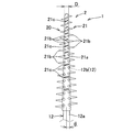
- the interdental cleaning tool 1 when distinguished by its function, includes a cleaning part 2 for interdental cleaning and a handle part 3 as a handle, and when distinguished by its material, A base portion 10 made of synthetic resin and a soft portion 20 made of an elastomer covering at least a part of the base portion 10 are provided.
- the base material portion 10 has a flat and slender plate-shaped handle base material portion 11 that constitutes the handle portion 3, and an elongated shaft-shaped core base material portion 12 that is continuous with the tip end portion of the handle base material portion 11. doing.
- the handle base 11 is formed in a flat elongated plate shape, but any other shape, such as a circular shape, an elliptical shape, or a polygonal shape, can be used as long as it has a shape that can be easily held and cleaned between teeth. It can also be formed in a planar rod shape. Further, a preferable example is one in which the handle base material portion 11 and the core base material portion 12 have a continuous shape, or a shape which is further curved in a plan view.
- the core base material portion 12 is formed in a substantially linear elongated shaft shape, an exposed portion 12a that is exposed to the outside is formed on the gripping portion side of the core base material portion 12, and the tip side portion of the core base material portion 12 is formed. Is coated with elastomer to form a core body 12b insertable between the teeth.
- the structure of the core base member 12 is not particularly limited, but the insertability of the cleaning unit between the teeth can be improved, and at the time of interdental cleaning, the interdental papilla of the interdental hourglass-shaped voids having different sizes is Since it is possible to obtain the additional effect of gently and gently massaging the book by using the interdental cleaning tool of the book, it is preferable to form the core base material portion 12 in a tapered shape in which the diameter is reduced toward the tip side thereof.
- the angle ⁇ formed by the taper shape with respect to the center line in the lengthwise direction of the base material portion 12 is more preferably set to 0.2° to 2.5°, and more preferably set to 0.2° to 1.8°. preferable.
- the diameter of the tip side portion of the lead body 12b is set to 0.4 mm to 0.6 mm, the diameter of the base end portion of the lead body 12b is set to 0.8 mm to 2.0 mm, and the lead of the cleaning soft portion 21 is set.
- the diameter D at the curved end portion of the tip portion of the covering portion 21a is set to 0.5 to 1.2 mm, and the tip side portion of the lead body 12b that is at least 5 mm or more from the tip portion of the lead body 12b is securely inserted between the teeth. It is configured to be able to.
- the angle ⁇ formed by the tapered shape of the core base material portion 12 is set to the same angle ⁇ over the entire length of the core base material portion 12, but becomes smaller continuously or stepwise toward the tip side of the core base material portion 12.
- the exposed portion 12a may be formed in a shaft shape having the same diameter over the entire length, and only the core main body 12b may be formed in a gentle taper shape in which the diameter is reduced toward the tip side. Further, it is possible to omit the exposed portion 12a and directly connect the lead body 12b to the handle base material portion 11.
- polypropylene (PP) and polybutylene terephthalate (PBT) are preferable because they can prevent the base material part 10 from breaking, and polypropylene has a low molding temperature, which can shorten the cycle time and improve productivity, and molding equipment. It is most preferable because it has a small heat load on.
- Additives such as fiber materials and minerals may be added to the synthetic resin material forming the base material portion 10.
- a fiber material for example, glass fiber, carbon fiber, aramid fiber or the like can be adopted.
- talc, mica, etc. can be adopted as minerals.
- the soft portion 20 is integrally formed by insert molding with the base material portion 10 using an elastomer material, and is provided with at least the cleaning soft portion 21 that is provided on the core base material portion 12.
- the soft portion 20 it is also possible to provide an annular insertion regulation portion that regulates the insertion between the teeth at the base end portion of the core body 12b, or provide the handle base material portion 11 with a slip prevention portion. ..
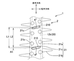
- the soft cleaning portion 21 is integrally formed with the core coating portion 21a that is coated on the core base material portion 12 and the core coating portion 21a, and is spaced outward in the length direction of the core base material portion 12 to the outside. It has a large number of protruding portions 21b formed in a protruding shape and a plurality of recessed portions 21c formed between the plurality of protruding portions 21b of the core covering portion 21a and elongated in a direction intersecting the longitudinal direction.
- the thickness of the core covering portion 21a is set to 0.08 mm to 0.2 mm.
- a plurality of recessed portions 21c are formed between the plurality of protruding portions 21b of the core covering portion 21a, and the outer peripheral surface of the core base material portion supported by the holding pins is exposed at the bottom surface portion of each recessed portion 21c (core base material portion exposed).
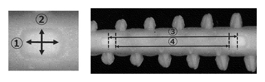
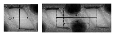
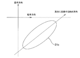
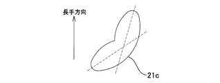
- the shape of the exposed core base material portion 210 is in both the longitudinal direction of the core base material portion 12 (core coating portion 21a) and the lateral direction orthogonal thereto as shown in FIG. The shape is elongated in the diagonal direction intersecting.
- the shape of the rectangle elongated in the diagonal direction is elliptical or arc-shaped at both ends, but the shape is not limited to this, and the elliptical shape ((a) and (b) in the figure) as illustrated in FIG. ((C) in the figure), approximately rectangular ((d) in the figure), bale type (oval type) ((e) in the figure), parallelogram ((f), (g) in the figure), hexagon ( (H) in the figure), octagon ((i) in the figure), egg shape (tear shape) (j, k in the figure), and other various polygons and irregular shapes (for example, FIG. 14).
- the shape is mentioned.
- the maximum dimension A1 at the position where the dimension along the longitudinal direction of the core base portion 12 is maximum is 0.25 mm or less, more preferably It is set to 0.22 mm or less. If the exposed portion of the core base material portion 210 at the bottom of the recess 21c is as thin as 0.25 mm or less, it is difficult for teeth or tartar to be caught during cleaning, and even if it is caught, the exposed portion of the core base material portion should be caught deeply.
- the concave portion has a shape extending diagonally as described above. Therefore, it avoids that the soft part for cleaning is peeled off from the joint surface with the core base material so that it is gradually cut cleanly along the diagonal direction with point contact with teeth and tartar like a blade. You can do it.
- a plurality of such recesses 21c are provided in a row along the longitudinal direction of the core coating 21a.
- the row of the plurality of concave portions 21c is formed on two side surfaces, that is, one side surface of the core coating portion 21a and the side surface on the opposite side in the circumferential direction.
- such a row of recesses 21c may be formed on three or more side surfaces.
- the central position of the core base material exposed portion 210 of the adjacent concave portions 21c between the concave portions 21c forming the rows, and both the longitudinal dimension and the lateral dimension of the exposed portion passing therethrough are maximized.
- the distance L1 between the center positions g1 is 2.1 mm or less.
- the adjacent cores may be removed in the middle of peeling. It is easy to reach the concave part and even if it largely peels off at the starting point of peeling, it is possible to finish thinly and cleanly the tip from the adjacent concave part, and it is possible to more reliably prevent it from becoming the starting point of catching or peeling again. become.
- the distance between the core base material exposed portions 210 on the line connecting the center positions g1 of the core base material exposed portions 210 of the adjacent recesses 21c (that is, the cleaning softness existing between the core base material exposed portions 210).
- the dimension L2 on the line is 0.5 mm or more.
- the soft portion 20 As the elastomer constituting the soft portion 20, styrene type, olefin type, polyamide type (for example, nylon type elastomer having 6 nylon, 6-6 nylon, 6-10 nylon, 6-12 nylon etc. as hard segment), urethane It is possible to employ thermoplastic elastomers such as those based on fluorine and fluorine, and thermosetting elastomers such as silicone rubber, natural rubber and synthetic rubber. In particular, a material having compatibility with the synthetic resin material forming the base material portion 10 is preferable. For example, when the base material portion 10 is made of polypropylene, the soft portion 20 is made of an olefin-based elastomer or a styrene-based elastomer. It is preferable.
- the method for manufacturing an interdental cleaning tool according to the present invention is such that at least a part of the core base material portion of the base material portion is set in a molding space of a mold for molding a soft part, and is substantially orthogonal to a mating surface of the mold.
- a core base material including a front end side portion and a base end side portion of the core base material portion, with at least two sets of holding pins, one set of two holding pins facing each other so as to project into the soft part for cleaning.
- the elastomer material is applied to the soft part for cleaning from the distal end side toward the base end side. So as to fill the molding space with an elastomer material to mold the soft part.
- the soft part molding part for cleaning the mold used in this step is formed integrally with the core covering part molding part for molding the core covering part for covering the core base material part, and the core base part. It has a large number of protrusion forming parts for forming a large number of protrusions that are formed so as to protrude outward at intervals in the longitudinal direction of the material part.
- the holding pin has a shape of an elongated tip end portion in a direction intersecting the longitudinal direction of the core base material portion, and is configured to project from the core coating portion molding portion between the protrusion molding portions into the cleaning soft portion molding portion.
- a plurality of recesses, which are formed between the plurality of protrusions of the core covering portion and are elongated in the direction intersecting the longitudinal direction, are formed in the portion that is arranged and holds the core base material portion.
- the tip end surface of the holding pin that abuts the core base material portion 12 may be a flat surface that is orthogonal to the axial direction of the holding pin, or may be an arc surface or an outer peripheral surface along the outer peripheral surface of the core base material portion 12. It may be configured by an arc surface having a smaller curvature. Among them, the surface shape along the outer peripheral surface is preferable in that the holding property of the core base material portion can be further improved.
- a base portion made of a synthetic resin and a soft portion made of an elastomer covering at least a part of the base portion are provided, and the base portion is a handle base portion and a tip end portion of the handle base portion.
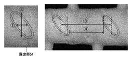
- Example 1 The sample of the interdental cleaning tool is Example 1 (FIG. 5) which is an interdental cleaning tool according to the representative embodiment (FIGS. 1 to 3) of the present application, and the shape of the exposed portion of the core base material which is the bottom of the recess. Is a circle (bale type) (Comparative Example 1) (FIG. 6), and the exposed portion of the core base material that is the bottom of the recess is a parallelogram.
- Comparative Example 3 which is an interdental cleaning tool manufactured by Reach Co., in which the exposed shape of the core base material portion that is the bottom of the recess is a parallelogram, a plurality of the same products are prepared, and the positions of the different recesses are different.
- a peeling test was performed in which the sample was fixed to a mount with a stapler (stapler) and the sample was pulled out to the base end side which is the handle base material side while the mount was supported so as not to move.
- the inclination angles of the outer shape of the core covering portion with respect to the longitudinal direction of the cleaning portion were 1.6 degrees in Example 1 and Comparative Example 1, 0.7 degrees in Comparative Example 2 and 1.1 degrees in Comparative Example 3, respectively.
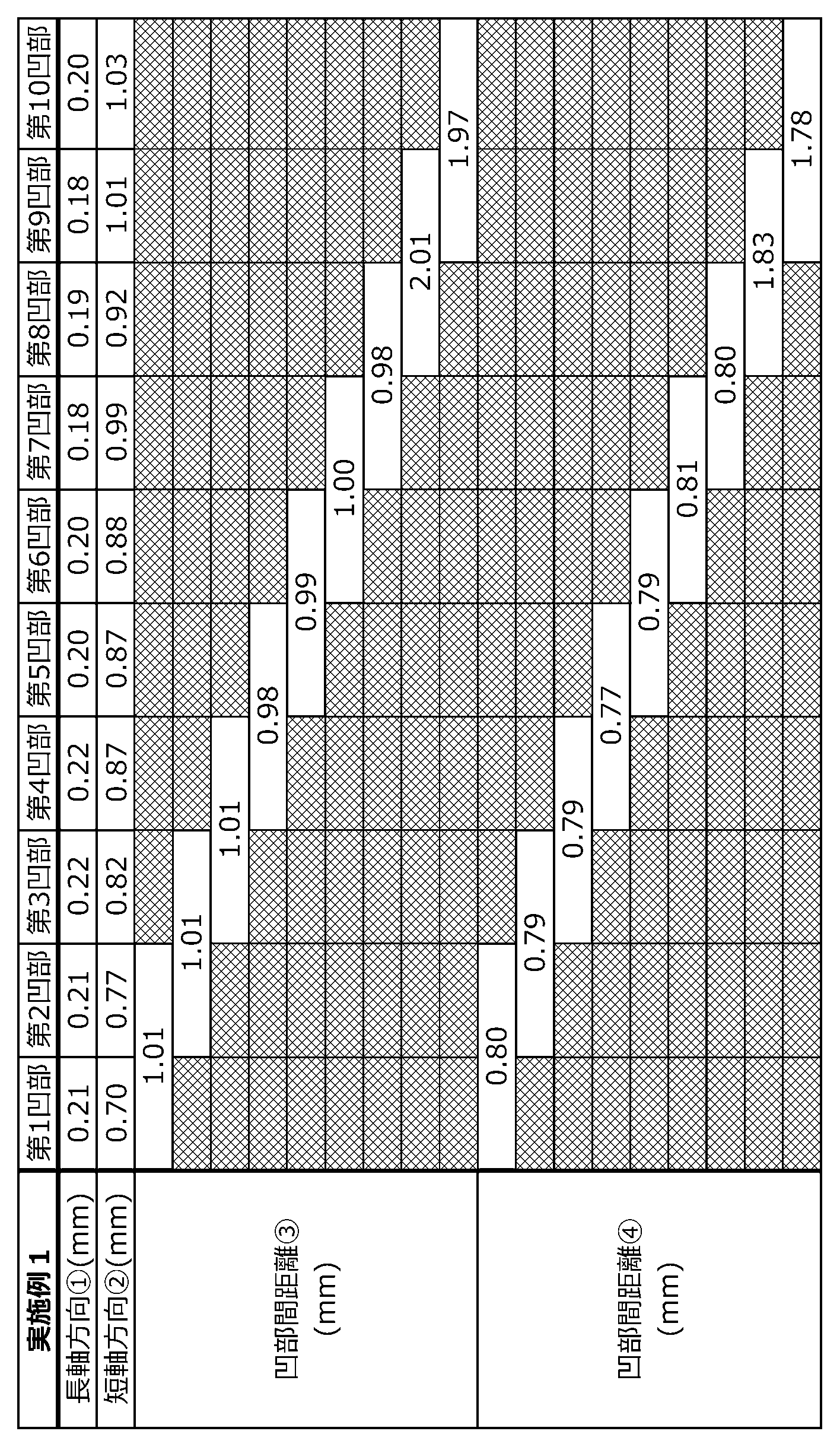
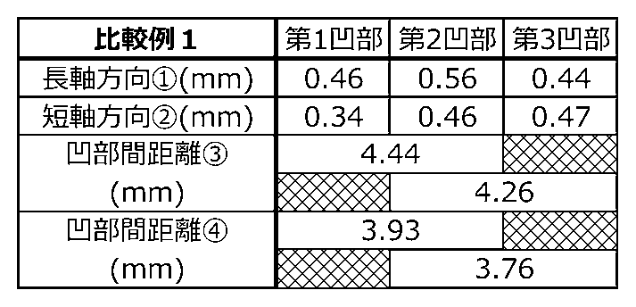
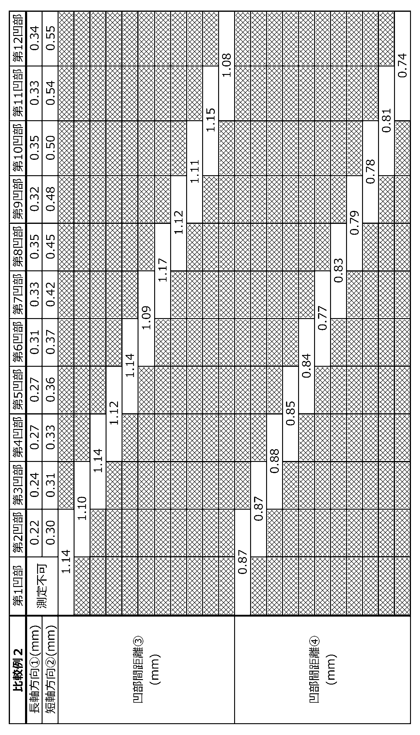
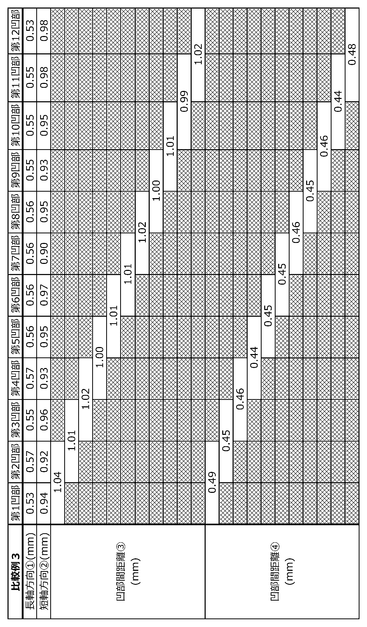
- Each of the samples of Example 1 and Comparative Examples 1 to 3 was provided with a plurality of concave portions arranged in a row on one side surface, and the numbers were 10 for Example 1, 3 for Comparative Example 1, and 2 for Comparative Example. Is 12 and Comparative Example 3 is 12.
- each size indicated by the numbers in FIGS. 5 to 8 is different for each recess. Specifically, as shown in Tables 1 to 4 below. It was the size of.
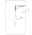
- a stapler needle (stapling needle for stapler) was used to fix the concave portion on the paper, forcing the peeling of the soft portion for cleaning. From this state, the peeling-off of the soft part for cleaning from the concave portion when the interdental cleaning tool was pulled out to the proximal end side from this state was analyzed.
- the stapler (stapling stapler) complies with Japanese Industrial Standard JIS S 6036-1992, and its thickness (width) is 0.48 mm. The thickness of the paper is 0.80 mm.
- Example 1 and Comparative Example 2 in which the core base material exposed portion has a shape that is long in the oblique direction and the distance between the center positions of the core base material exposed portions is about 0.9 to 2.1 mm, Even if deep peeling occurs from the concave portion 21c, it reaches the adjacent concave portion in the middle of peeling and is gradually cut along the oblique direction by point contact with teeth or tartar like a blade at the adjacent concave portion, and It can be seen that although peeling continues toward the concave portion, it does not reach the next concave portion and ends halfway.
- the cleaning soft part between the recesses is short as in Comparative Example 3, the cleaning soft part is peeled from the core base material and moves largely, and thus it cannot be cut along the oblique direction as described above. I understand that it will tear off. From this, the central position in the exposed portion of each core base material portion of the recess adjacent to each other in the longitudinal direction, and the central position where both the dimension in the longitudinal direction and the dimension in the lateral direction of the exposed portion passing therethrough are maximum. It is understood that the distance between the exposed portions of the core base material portions of the adjacent recesses on the line connecting the two should be set to 0.5 mm or more, and more preferably 0.7 mm or more.
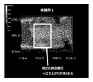
- Example 1 the end of peeling is gradually thinned between the recesses, and ends in comparison with Comparative Example 1.
- the step ends are not thinned.
- the image of Example 1 in FIG. 9 is the eighth recess
- the image of Comparative Example 1 in FIG. 10 is the second recess
- the image in Comparative Example 2 in FIG. 11 is the fourth recess.
- Example 1 in the concave portion adjacent to the concave portion that was the starting point of peeling, it was cut neatly like a knife, and then gradually thinned and finished peeling cleanly, In Comparative Example 1, it can be seen that the adjacent recesses are circular, such cutting does not occur, and peeling ends in a state of rising in a step shape.
- Comparative Example 2 as compared with Example 1, since the maximum dimension of the position where the dimension of the exposed portion of the core base portion of the recess along the cleaning unit longitudinal direction is the maximum is large, it becomes the starting point of peeling. In the concave portion adjacent to the concave portion, the stapler needle (stapling staple needle) moves to the bottom side of the concave portion again, and the entire cleaning unit is unstable and shakes. It is considered that a clean cut does not occur, and as a result, the peeling ends in a step-like manner even though it is between the concave portions. It can be seen that the maximum dimension of the exposed portion of the core base portion along the longitudinal direction of the cleaning portion may be set to 0.25 mm or less, more preferably 0.22 mm or less as in the first embodiment.
Landscapes
- Health & Medical Sciences (AREA)
- Dentistry (AREA)
- Epidemiology (AREA)
- Life Sciences & Earth Sciences (AREA)
- Animal Behavior & Ethology (AREA)
- General Health & Medical Sciences (AREA)
- Public Health (AREA)
- Veterinary Medicine (AREA)
- Brushes (AREA)
Abstract
Description
(1) 合成樹脂からなる基材部と、該基材部の少なくとも一部を被覆するエラストマからなる軟質部とを備え、前記基材部は、ハンドル基材部と、該ハンドル基材部の先端部に連設した細長い軸状の芯基材部とを有し、前記軟質部は、前記芯基材部をインサート成形により被覆する清掃用軟質部を少なくとも有し、前記芯基材部と清掃用軟質部とからなり、先端側ほど細くなる歯間清掃用の清掃部を備えた歯間清掃具であって、前記清掃用軟質部は、芯基材部を被覆する芯被覆部と、前記インサート成形時の保持ピンにより形成される凹部である複数の凹部とを有し、前記凹部は、前記芯基材部の長手方向に沿って複数形成されるとともに、各凹部の芯基材部露出部分は、前記長手方向およびこれに直交する短手方向の双方に交差する斜め方向に細長い形状で、且つ、前記長手方向の寸法が最大となる位置の当該最大寸法が0.25mm以下であることを特徴とする歯間清掃具。
歯間清掃具の試料は、本願の代表的実施形態(図1~図3)のとおりの歯間清掃具である実施例1(図5)、凹部底部である芯基材部露出部分の形状が円形(俵型)である比較例1(図6)、凹部底部である芯基材部露出部分の形状が平行四辺形のクリエイト社製歯間清掃具である比較例2(図7)、凹部底部である芯基材部露出部分の形状が平行四辺形のリーチ社製歯間清掃具である比較例3(図8)について、それぞれ同じものを複数個用意し、各々異なる凹部の位置をホッチキス(ステープラ)で台紙に固定し、台紙を動かないように支持した状態で試料をハンドル基材部側である基端側に引き抜く剥離試験を行った。
剥離試験は、図4に示すように、各試料の複数の凹部の各位置にて、ホッチキス針(ステープラ用つづり針)で紙にとめ、これにより強制的に当該凹部を清掃用軟質部の剥がれの起点とし、この状態から歯間清掃具を基端側に引き抜いたときの当該凹部を起点とする清掃用軟質部の剥がれ方を解析した。ホッチキス針(ステープラ用つづり針)は、日本工業規格のJIS S 6036-1992に適合するものであり、その太さ(幅)は0.48mmである。紙の厚さは0.80mmである。
解析は、各凹部からの長手方向の剥がれ距離および剥がれた面積をデジタルマイクロスコープ(キーエンス社製VHX-6000)にて測定した。また、特定の凹部からの剥がれた痕の状態をレーザー顕微鏡(キーエンス社製VK-X150)で撮影した(後述の顕微鏡解析画像図9~図11)。剥がれ距離および剥がれた面積は、下記表5に示すとおりとなった。なお、比較例3については、凹部間の清掃用軟質部が容易に動いて千切れてしまい、測定不能であった。
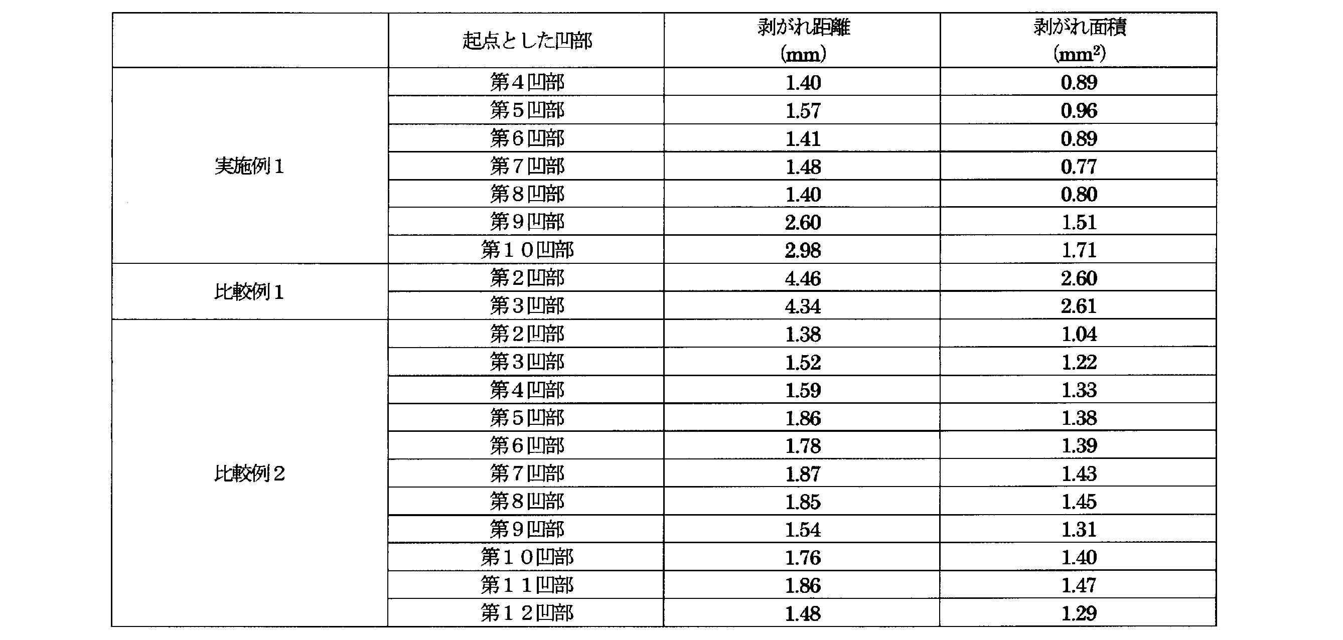
表5の結果から分かるように、実施例1、比較例2では、いずれの凹部を剥がれの起点とした場合でも、すべて凹部間距離の約1.5倍の位置で剥がれが終了している。これに対し、比較例1では、比較的凹部間距離が長いにもかかわらず隣りの凹部まで剥がれが終了せず、当該隣りの凹部の位置で剥がれが終了している。
2 清掃部
3 ハンドル部
10 基材部
11 ハンドル基材部
12 芯基材部
12a 露出部
12b 芯本体
20 軟質部
21 清掃用軟質部
21a 芯被覆部
21b 突起部
21c 凹部
210 芯基材部露出部分
Claims (3)
- 合成樹脂からなる基材部と、該基材部の少なくとも一部を被覆するエラストマからなる軟質部とを備え、
前記基材部は、ハンドル基材部と、該ハンドル基材部の先端部に連設した細長い軸状の芯基材部とを有し、
前記軟質部は、前記芯基材部をインサート成形により被覆する清掃用軟質部を少なくとも有し、
前記芯基材部と清掃用軟質部とからなり、先端側ほど細くなる歯間清掃用の清掃部を備えた歯間清掃具であって、
前記清掃用軟質部は、芯基材部を被覆する芯被覆部と、前記インサート成形時の保持ピンにより形成される凹部である複数の凹部とを有し、
前記凹部は、前記芯基材部の長手方向に沿って複数形成されるとともに、各凹部の芯基材部露出部分は、前記長手方向およびこれに直交する短手方向の双方に交差する斜め方向に細長い形状で、且つ、前記長手方向の寸法が最大となる位置の当該最大寸法が0.25mm以下であることを特徴とする歯間清掃具。 - 長手方向に隣接する前記凹部の前記芯基材部露出部分の幾何中心間の距離が2.1mm以下である請求項1記載の歯間清掃具。
- 長手方向に隣接する前記凹部の前記芯基材部露出部分の幾何中心を結ぶ線上における、前記隣接する凹部の芯基材部露出部分間の距離が、0.5mm以上である、請求項1又は2記載の歯間清掃具。
Priority Applications (3)
| Application Number | Priority Date | Filing Date | Title |
|---|---|---|---|
| US17/417,303 US12495888B2 (en) | 2018-12-28 | 2019-12-26 | Interdental cleaning tool |
| EP19903432.3A EP3903635B1 (en) | 2018-12-28 | 2019-12-26 | Interdental cleaning tool |
| CN201980086947.XA CN113226116A (zh) | 2018-12-28 | 2019-12-26 | 齿间清扫工具 |
Applications Claiming Priority (2)
| Application Number | Priority Date | Filing Date | Title |
|---|---|---|---|
| JP2018-248440 | 2018-12-28 | ||
| JP2018248440A JP7188077B2 (ja) | 2018-12-28 | 2018-12-28 | 歯間清掃具 |
Publications (1)
| Publication Number | Publication Date |
|---|---|
| WO2020138331A1 true WO2020138331A1 (ja) | 2020-07-02 |
Family
ID=71125939
Family Applications (1)
| Application Number | Title | Priority Date | Filing Date |
|---|---|---|---|
| PCT/JP2019/051228 Ceased WO2020138331A1 (ja) | 2018-12-28 | 2019-12-26 | 歯間清掃具 |
Country Status (5)
| Country | Link |
|---|---|
| US (1) | US12495888B2 (ja) |
| EP (1) | EP3903635B1 (ja) |
| JP (1) | JP7188077B2 (ja) |
| CN (1) | CN113226116A (ja) |
| WO (1) | WO2020138331A1 (ja) |
Cited By (1)
| Publication number | Priority date | Publication date | Assignee | Title |
|---|---|---|---|---|
| USD1021416S1 (en) | 2021-03-02 | 2024-04-09 | Esro Ag | Interdental cleaner |
Families Citing this family (1)
| Publication number | Priority date | Publication date | Assignee | Title |
|---|---|---|---|---|
| DE102018008963B4 (de) * | 2018-11-14 | 2021-03-18 | lnterbros GmbH | lnterdental-Reiniger |
Citations (2)
| Publication number | Priority date | Publication date | Assignee | Title |
|---|---|---|---|---|
| WO2013176297A1 (ja) | 2012-05-24 | 2013-11-28 | サンスター スイス エスエー | 歯間清掃具の製造方法及び歯間清掃具 |
| JP2016087362A (ja) | 2014-11-11 | 2016-05-23 | サンスター株式会社 | 歯間清掃具及びその製造方法 |
Family Cites Families (7)
| Publication number | Priority date | Publication date | Assignee | Title |
|---|---|---|---|---|
| EP2866610A1 (de) * | 2012-07-02 | 2015-05-06 | Trisa Holding AG | Verfahren zur herstellung von bürsten, insbesondere interdentalbürsten, sowie bürste, insbesondere interdentalbürste und produktgruppe aus mehreren bürsten |
| US20150257861A1 (en) * | 2014-03-17 | 2015-09-17 | Ranir, Llc | Interproximal cleaning tool and method of manufacture |
| WO2016076241A1 (ja) * | 2014-11-11 | 2016-05-19 | サンスター株式会社 | 歯間清掃具 |
| JP6409825B2 (ja) * | 2015-06-08 | 2018-10-24 | サンスター スイス エスエー | 歯間清掃具の製造方法 |
| JP6750328B2 (ja) * | 2015-06-12 | 2020-09-02 | サンスター株式会社 | 歯間清掃具 |
| JP6455422B2 (ja) * | 2015-12-28 | 2019-01-23 | サンスター株式会社 | 歯間清掃具 |
| DE102017010559A1 (de) * | 2017-11-15 | 2019-05-16 | Interbros Gmbh | Interdentalreiniger und Spritzgussvorrichtung zur Herstellung eines Interdentalreinigers |
-
2018
- 2018-12-28 JP JP2018248440A patent/JP7188077B2/ja active Active
-
2019
- 2019-12-26 WO PCT/JP2019/051228 patent/WO2020138331A1/ja not_active Ceased
- 2019-12-26 CN CN201980086947.XA patent/CN113226116A/zh active Pending
- 2019-12-26 EP EP19903432.3A patent/EP3903635B1/en active Active
- 2019-12-26 US US17/417,303 patent/US12495888B2/en active Active
Patent Citations (2)
| Publication number | Priority date | Publication date | Assignee | Title |
|---|---|---|---|---|
| WO2013176297A1 (ja) | 2012-05-24 | 2013-11-28 | サンスター スイス エスエー | 歯間清掃具の製造方法及び歯間清掃具 |
| JP2016087362A (ja) | 2014-11-11 | 2016-05-23 | サンスター株式会社 | 歯間清掃具及びその製造方法 |
Non-Patent Citations (1)
| Title |
|---|
| See also references of EP3903635A4 |
Cited By (1)
| Publication number | Priority date | Publication date | Assignee | Title |
|---|---|---|---|---|
| USD1021416S1 (en) | 2021-03-02 | 2024-04-09 | Esro Ag | Interdental cleaner |
Also Published As
| Publication number | Publication date |
|---|---|
| JP7188077B2 (ja) | 2022-12-13 |
| EP3903635A4 (en) | 2022-08-10 |
| US12495888B2 (en) | 2025-12-16 |
| JP2022065207A (ja) | 2022-04-27 |
| CN113226116A (zh) | 2021-08-06 |
| EP3903635B1 (en) | 2026-01-28 |
| US20230200523A1 (en) | 2023-06-29 |
| EP3903635A1 (en) | 2021-11-03 |
Similar Documents
| Publication | Publication Date | Title |
|---|---|---|
| KR101971310B1 (ko) | 칫솔 | |
| JP6069311B2 (ja) | 歯間清掃具の製造方法及び歯間清掃具 | |
| JP6547828B2 (ja) | 歯間清掃具 | |
| KR20170116245A (ko) | 칫솔 | |
| JP6915234B2 (ja) | 歯間清掃具 | |
| CN107106273A (zh) | 牙缝清洁工具 | |
| CN111480969B (zh) | 牙刷 | |
| WO2014065368A1 (ja) | 歯間清掃具 | |
| JP6750328B2 (ja) | 歯間清掃具 | |
| JP7188077B2 (ja) | 歯間清掃具 | |
| JP2011024839A (ja) | 歯ブラシ | |
| WO2016167191A1 (ja) | 歯間ブラシ | |
| CN113995223B (zh) | 牙刷 | |
| JP6281586B2 (ja) | 歯間清掃具 | |
| KR102892717B1 (ko) | 칫솔 | |
| JP2020081087A (ja) | 歯間清掃具、歯間清掃具の本体、歯間清掃具の製造方法、および金型 | |
| TW201313156A (zh) | 牙刷 | |
| JP7575886B2 (ja) | 歯間清掃具 | |
| JPH09327334A (ja) | 歯間ブラシの製造方法およびその装置 | |
| JP2012217468A (ja) | 歯ブラシ | |
| KR20250162015A (ko) | 칫솔 | |
| JP2024052101A (ja) | 歯ブラシ | |
| JP2024052102A (ja) | 歯ブラシ | |
| JP2021178114A (ja) | 歯ブラシ | |
| JP2021178113A (ja) | 歯ブラシ |
Legal Events
| Date | Code | Title | Description |
|---|---|---|---|
| 121 | Ep: the epo has been informed by wipo that ep was designated in this application |
Ref document number: 19903432 Country of ref document: EP Kind code of ref document: A1 |
|
| NENP | Non-entry into the national phase |
Ref country code: DE |
|
| ENP | Entry into the national phase |
Ref document number: 2019903432 Country of ref document: EP Effective date: 20210728 |
|
| NENP | Non-entry into the national phase |
Ref country code: JP |
|
| WWG | Wipo information: grant in national office |
Ref document number: 17417303 Country of ref document: US |
|
| WWG | Wipo information: grant in national office |
Ref document number: 2019903432 Country of ref document: EP |