WO2020138391A1 - Système d'alimentation en air - Google Patents
Système d'alimentation en air Download PDFInfo
- Publication number
- WO2020138391A1 WO2020138391A1 PCT/JP2019/051357 JP2019051357W WO2020138391A1 WO 2020138391 A1 WO2020138391 A1 WO 2020138391A1 JP 2019051357 W JP2019051357 W JP 2019051357W WO 2020138391 A1 WO2020138391 A1 WO 2020138391A1
- Authority
- WO
- WIPO (PCT)
- Prior art keywords
- supply
- air
- ecu
- regenerative
- regeneration
- Prior art date
- Legal status (The legal status is an assumption and is not a legal conclusion. Google has not performed a legal analysis and makes no representation as to the accuracy of the status listed.)
- Ceased
Links
Images






Classifications
-
- B—PERFORMING OPERATIONS; TRANSPORTING
- B60—VEHICLES IN GENERAL
- B60T—VEHICLE BRAKE CONTROL SYSTEMS OR PARTS THEREOF; BRAKE CONTROL SYSTEMS OR PARTS THEREOF, IN GENERAL; ARRANGEMENT OF BRAKING ELEMENTS ON VEHICLES IN GENERAL; PORTABLE DEVICES FOR PREVENTING UNWANTED MOVEMENT OF VEHICLES; VEHICLE MODIFICATIONS TO FACILITATE COOLING OF BRAKES
- B60T17/00—Component parts, details, or accessories of power brake systems not covered by groups B60T8/00, B60T13/00 or B60T15/00, or presenting other characteristic features
- B60T17/002—Air treatment devices
- B60T17/004—Draining and drying devices
-
- B—PERFORMING OPERATIONS; TRANSPORTING
- B01—PHYSICAL OR CHEMICAL PROCESSES OR APPARATUS IN GENERAL
- B01D—SEPARATION
- B01D2258/00—Sources of waste gases
- B01D2258/06—Polluted air
-
- B—PERFORMING OPERATIONS; TRANSPORTING
- B01—PHYSICAL OR CHEMICAL PROCESSES OR APPARATUS IN GENERAL
- B01D—SEPARATION
- B01D2259/00—Type of treatment
- B01D2259/45—Gas separation or purification devices adapted for specific applications
- B01D2259/4566—Gas separation or purification devices adapted for specific applications for use in transportation means
-
- B—PERFORMING OPERATIONS; TRANSPORTING
- B01—PHYSICAL OR CHEMICAL PROCESSES OR APPARATUS IN GENERAL
- B01D—SEPARATION
- B01D53/00—Separation of gases or vapours; Recovering vapours of volatile solvents from gases; Chemical or biological purification of waste gases, e.g. engine exhaust gases, smoke, fumes, flue gases, aerosols
- B01D53/26—Drying gases or vapours
- B01D53/261—Drying gases or vapours by adsorption
Definitions
- the present invention relates to an air supply system that supplies compressed air to equipment.
- compressed air sent from a compressor is used to control the pneumatic system including brakes and suspensions.
- the compressed air contains liquid impurities such as water contained in the atmosphere and oil that lubricates the inside of the compressor. If compressed air containing a large amount of water and oil enters the pneumatic system, it causes rust and swelling of the rubber member, which causes malfunction. Therefore, an air dryer that removes impurities such as water and oil in the compressed air is provided downstream of the compressor.
- the air dryer performs a dehumidifying operation that removes oil and water from compressed air and a regeneration operation that removes the oil and water adsorbed by the desiccant from the desiccant and discharges it as drain.
- Patent Document 1 describes a technique for an air dryer to perform a reproducing operation.
- the air supply system described in Patent Document 1 stores the air compressed by the air compressor in the air tank.
- the air supply system drives the air compressor to supply compressed air to the air tank until the air pressure reaches the second pressure.
- the air supply system stops the supply of compressed air to the air tank by the air compressor and opens the discharge valve (purge valve).
- the air supply system then performs a regenerating operation in which the compressed air in the air tank is passed through the air dryer and discharged to the atmosphere by maintaining the valve open state until the air pressure decreases to the third pressure.
- the air supply system closes the discharge valve when the air pressure in the air tank reaches the third pressure.
- the regeneration operation of the air dryer is performed by the compressed air in the air tank.
- the regeneration is driven by the rotation of the engine during no-load operation such as when the engine is not injecting fuel, which is the timing when the engine rotation is not used for traveling.
- the technology of supply is known.
- the starting condition of the regenerative supply is related to the vehicle state, while the starting condition of the above-described regeneration operation is related to the air pressure. Therefore, both start conditions may be satisfied. When both start conditions are satisfied, the regeneration operation and the regenerative supply are simultaneously performed.
- the compressed air that is regenerated and supplied may be discharged, and the effect of reducing the engine load may be lost, or because the regeneration time of the air dryer does not reach the specified value, sufficient regeneration may not be performed, resulting in defective regeneration of the air dryer. May occur. That is, there is room for improvement in adjusting the execution timings of the regeneration operation and the regeneration supply.
- An object of the present invention is to provide an air supply system capable of improving the fuel consumption associated with driving a compressor.
- An air supply system that achieves the above object is an air supply system that performs a supply operation of flowing compressed air supplied from a compressor from an upstream side to a downstream side through an air dryer having a filter and a check valve.
- the control device includes a pressure sensor that detects an air pressure downstream of the stop valve, a control device that switches the supply operation and the non-supply operation, and performs a regeneration operation that regenerates the filter during the non-supply operation. , A supply start value for starting the supply operation based on a comparison with the detected air pressure detected by the pressure sensor, and a supply stop value higher than the supply start value, based on a comparison with the detected air pressure.
- the supply stop value for starting the non-supply operation the controller is not performing the regeneration operation, and the detected air pressure is higher than the supply start value and lower than the supply stop value. And a condition including that the engine driving the compressor is under no-load operation, the supply operation is executed by regenerative supply.
- the compressor is driven by the rotation of the engine to supply compressed air.
- Regenerative supply is performed prior to the supply of compressed air by the normal supply operation, and supplements the supply of compressed air by the normal supply operation. Further, during this regenerative supply, the engine does not consume fuel for driving the compressor, so that the fuel efficiency of the engine can be improved. Therefore, it is possible to improve fuel efficiency related to driving the compressor.
- the no-load operation of the engine may include no fuel injection of the engine.
- the rotation of the engine is effectively used for air supply when the engine is not injecting fuel.
- control device may continue the regenerative supply for 10 seconds or more. In this case, when the compressor switches from the no-load operation to the load operation, it is possible to avoid the occurrence of the timing at which the compressed air is not supplied due to the supply delay of the compressed air.
- the condition may further include that the detected air pressure is equal to or lower than a predetermined air pressure.
- the compressor when the compressor is switched from the no-load operation to the load operation, it is possible to suppress the occurrence of the timing at which the compressed air is not supplied due to the supply delay of the compressed air.
- control device may not start the regenerative supply when the regeneration operation is being performed. In this case, the regenerating operation is not wasted due to the regenerative supply. Further, the regeneration performance does not deteriorate due to the interruption of the regeneration operation due to the regeneration supply.
- control device may obtain from the control device of the vehicle that the engine is in a no-load operation. In this case, it can be acquired from the control device of the vehicle that the engine is under no-load operation.
- FIG. 4 is a diagram showing an operation mode of the air dryer in the same embodiment, (a) showing a supply action, (b) showing a purge action, and (c) showing a regeneration action.
- the graph which shows the timing which performs a regeneration operation etc. in the same embodiment.
- the flowchart which shows the procedure which performs the regeneration operation in the same embodiment.
- the flowchart which shows the procedure which performs the regeneration operation in the same embodiment.
- the flowchart which shows the procedure which performs the regeneration operation in the same embodiment.
- the flowchart which shows the procedure which performs the regeneration operation in the same embodiment.
- the flowchart which shows the procedure which performs the regeneration operation in the same embodiment.
- the flowchart which shows the procedure which performs the regeneration operation in the
- FIGS. 1 to 4 An embodiment of an air supply system included in the pneumatic system will be described with reference to FIGS. 1 to 4.
- the air supply system is installed in automobiles such as trucks, buses, and construction machines.
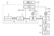
- the compressor 4, the air dryer 11, the protection valve 12, the air tank 13, the brake valve 14, and the brake chamber 15 are sequentially connected via the air supply passages 4E, 11E, 12E, 13E, 14E.
- the compressor 4, the air dryer 11, and the protection valve 12 constitute the air supply system 10.
- the compressor 4 is driven by the power of an automobile engine (not shown), compresses air, and supplies compressed air to the air supply system 10.
- the compressor 4 is connected to the air dryer 11 via an air supply passage 4E.
- the air sent from the compressor 4 passes through the filter 17 (see FIG. 2) to capture impurities in the air and clean the air.
- the air thus cleaned is supplied from the air dryer 11 to the air tank 13 via the air supply passage 11E, the protection valve 12 and the air supply passage 12E.
- the air tank 13 is connected to a brake valve 14 operated by a driver via an air supply passage 13E.
- the brake valve 14 is connected to the brake chamber 15 via an air supply passage 14E. Therefore, in response to the operation of the brake valve 14, air is supplied to the brake chamber 15, whereby the service brake is activated.
- the air supply system 10 also includes an ECU 80 as a control device.
- the ECU 80 is electrically connected to the air dryer 11 via wirings E62 and E63. Further, the ECU 80 is electrically connected to the pressure sensor 65 via the wiring E65.
- the ECU 80 detects the air pressure in the protection valve 12 by the pressure sensor 65. From the detection signal of the pressure sensor 65, the detected air pressure corresponding to the air pressure of the air tank 13 is obtained. Further, the ECU 80 is connected to the temperature/humidity sensor 66 via a wiring E66.
- the ECU 80 detects the humidity of the compressed air in the air tank 13 using the temperature/humidity sensor 66. Further, the ECU 80 is electrically connected to the vehicle ECU 100 so that various signals of the vehicle equipped with the air supply system 10 can be obtained.
- the ECU 80 includes an arithmetic unit, a volatile storage unit, and a non-volatile storage unit, which are not shown, and gives signals to the air dryer 11 for designating various operations in accordance with a program stored in the non-volatile storage unit. Further, the ECU 80 has a timer used for measuring the period related to the reproduction operation.
- the air supply system 10 will be described with reference to FIG.
- the air dryer 11 has a maintenance port P12.
- the maintenance port P12 is a port for supplying air upstream of the filter 17 of the air dryer 11 at the time of maintenance.
- the ECU 80 is electrically connected to the regeneration control valve 21 of the air dryer 11 via a wire E63 and electrically connected to the governor 26 of the air dryer 11 via a wire E62.
- the air dryer 11 includes a filter 17 in the internal space 11A.
- the filter 17 is provided in the middle of an air supply passage 18 that connects the air supply passage 4E from the compressor 4 located upstream and the air supply passage 11E connected to the protection valve 12 located downstream.
- the filter 17 contains a desiccant and has a filtering unit.
- the filter 17 removes moisture contained in the air from the air by passing the air through a desiccant to dry the air, and removes oil contained in the air by a filtering unit to purify the air.
- the air that has passed through the filter 17 is supplied to the protection valve 12 via a check valve 19 as a check valve that allows only the air flow to the filter 17 downstream. That is, the check valve 19 allows only the flow of air from upstream to downstream when the filter 17 is upstream and the protection valve 12 is downstream.
- the check valve 19 is provided with a bypass flow passage 20 that bypasses the check valve 19 in parallel with the check valve 19.
- a regeneration control valve 21 is connected to the bypass passage 20.
- the regeneration control valve 21 is a solenoid valve controlled by the ECU 80.
- the ECU 80 switches the operation of the regeneration control valve 21 by controlling the power on/off (driving/non-driving) of the regeneration control valve 21 via the wiring E63.
- the regeneration control valve 21 is closed when the power is off to seal the bypass flow passage 20, and is opened when the power is on to communicate the bypass flow passage 20.
- the regeneration control valve 21 is driven when the value of the detected air pressure exceeds the supply stop value.
- the bypass passage 20 is provided with an orifice 22 between the regeneration control valve 21 and the filter 17.
- the regeneration control valve 21 When the regeneration control valve 21 is energized, the compressed air in the air tank 13 is sent to the filter 17 through the protection valve 12 and the bypass passage 20 while the flow rate is regulated by the orifice 22.
- the compressed air sent to the filter 17 flows backward from the downstream side to the upstream side of the filter 17.
- Such a process is a process for regenerating the filter 17, and is called a regenerating process for the air dryer.
- the dried and cleaned compressed air in the air tank 13 flows back through the filter 17, so that the water and oil components captured by the filter 17 are removed from the filter 17.
- the regeneration control valve 21 is controlled to open for a predetermined period. This predetermined period is a period during which the filter 17 can be regenerated, and is set logically, experimentally or empirically.
- a branch passage 16 branches from a portion between the compressor 4 and the filter 17.
- a drain discharge valve 25 is provided in the branch passage 16, and a drain discharge port 27 is connected to the end of the branch passage 16.
- the drain containing water and oil removed from the filter 17 is sent to the drain discharge valve 25 together with the compressed air.
- the drain discharge valve 25 is an air pressure driven valve that is driven by air pressure, and is provided in the branch passage 16 between the filter 17 and the drain discharge port 27.
- the drain discharge valve 25 is a 2-port 2-position valve that changes its position between a closed position and an open position. When the drain discharge valve 25 is in the open position, the drain is sent to the drain discharge port 27.
- the drain discharged from the drain outlet 27 may be collected by an oil separator (not shown).
- the drain discharge valve 25 is controlled by the governor 26.
- the governor 26 is a solenoid valve controlled by the ECU 80.
- the ECU 80 switches the operation of the governor 26 by controlling turning on/off (driving/non-driving) of the power of the governor 26 via the wiring E62.
- the governor 26 opens the drain discharge valve 25 by inputting an unload signal having a predetermined air pressure to the drain discharge valve 25.
- the governor 26 closes the drain discharge valve 25 by opening the port of the drain discharge valve 25 to the atmospheric pressure without inputting the unload signal to the drain discharge valve 25.
- the drain discharge valve 25 is maintained in the closed position without the unload signal input from the governor 26, and switches to the open position when the unload signal is input from the governor 26. Further, when the input port connected to the compressor 4 in the drain discharge valve 25 exceeds the upper limit value and becomes high in pressure, the drain discharge valve 25 is forcibly switched to the open position.
- the compressor 4 performs a load operation that supplies compressed air and a no-load operation that does not supply compressed air.
- the governor 26 controls switching between the loaded operation and the unloaded operation of the compressor 4. When the power is turned on, the governor 26 sends an unload signal to the compressor 4 to cause the compressor 4 to perform no-load operation. When the power is turned off, the governor 26 does not input the unload signal to the compressor 4 and opens the port of the compressor 4 to the atmosphere, thereby causing the compressor 4 to perform the load operation.
- the ECU 80 switches the governor 26 to a supply position for outputting an unload signal by turning on (driving) the power of the governor 26 based on the air pressure detected by the pressure sensor 65.
- the ECU 80 switches the governor 26 to a non-supply position where the unload signal is not output by turning off the power of the governor 26 (making it non-driven) based on the air pressure detected by the pressure sensor 65.
- the supply operation is an operation of supplying compressed air to the air tank 13.
- the purging operation is an operation in which the compressor is stopped for purging processing or the like.
- the regenerating operation is an operation of regenerating the filter 17. The regenerating operation and the purging operation constitute a non-supplying operation.
- the ECU 80 closes the regeneration control valve 21 and the governor 26 (indicated as “CLOSE” in the figure).
- the drive signal (power source) from the ECU 80 is not supplied to the regeneration control valve 21 and the governor 26. Therefore, the governor 26 opens the port of the compressor 4 and the port of the drain discharge valve 25, which are connected downstream, to the atmosphere.
- the compressor 4 supplies compressed air (described as "ON” in the figure).
- the compressed air (indicated as “IN” in the figure) supplied to the air dryer 11 is supplied to the air tank 13 via the protection valve 12 after the water content and the oil content are removed by the filter 17 (“OUT” in the figure). Stated).
- the ECU 80 closes the regeneration control valve 21 and opens the governor 26 (indicated as “OPEN” in the figure).
- the governor 26 opens by being supplied with a drive signal (power source) from the ECU 80, and the port of the compressor 4 and the port of the drain discharge valve 25, which are connected to the downstream side, are respectively upstream (the protection valve 12).
- the compressor 4 is in the no-load operation state (described as “OFF” in the drawing) by the unload signal (described as “CONT” in the drawing) from the governor 26, and the compressor 4 is in the filter 17 and the air supply passage 18. Compressed air is discharged from the drain discharge port 27 together with water, oil and the like.
- the ECU 80 opens the regeneration control valve 21 and the governor 26, respectively.
- a drive signal (power source) from the ECU 80 is supplied to the regeneration control valve 21 and the governor 26.
- the unload signal from the governor 26 causes the compressor 4 to be in a no-load operation state.
- the regeneration control valve 21 and the drain discharge valve 25 are opened, so that the compressed air on the side of the protection valve 12 with respect to the filter 17 flows downstream of the filter 17 (the desiccant contained therein). The reverse flow is performed from the upstream side to the upstream side, and the regeneration processing of the filter 17 is performed.
- the ECU 80 is provided with a supply start value CI which is a value corresponding to the air pressure at which the air supply by the compressor 4 is started, and a supply stop value CO which is a value corresponding to the air pressure at which the air supply by the compressor 4 is stopped. .. Further, the ECU 80 is provided with a regeneration threshold value Cth that is less than the supply stop value CO and higher than the supply start value CI.
- the supply stop value CO, the supply start value CI, and the regeneration threshold value Cth may be stored in the nonvolatile storage unit of the ECU 80 or the like. Further, the ECU 80 can measure the period of the regenerative operation using a timer.
- the state of the compressor 4 is also related to the operation of the air dryer 11.
- the air dryer 11 performs the purging operation
- the state of the compressor 4 is “regeneration”
- the air dryer 11 performs the regenerating operation
- the state of the compressor 4 is “normal”, the air dryer 11 is The air dryer 11 performs the supply operation even when the state of the compressor 4 is “regeneration”.
- the supply operation is usually started on condition that the air pressure is equal to or lower than the supply start value CI.
- the operation started on the condition that a predetermined condition is satisfied is particularly referred to as a regenerative operation.
- the predetermined condition is that the air dryer 11 is not performing the regenerating operation, that the detected air pressure is equal to or lower than the regeneration threshold Cth that is higher than the supply start value CI and lower than the supply stop value CO, and That is, the engine driving No. 4 is under no-load operation.
- the fact that the engine is under no-load operation includes the time when no fuel is injected into the engine.
- the ECU 80 compares the detected air pressure, which is the air pressure detected by the pressure sensor 65, with the supply start value CI.
- the ECU 80 switches the air dryer 11 to the supply operation in order to supply the compressed air to the air tank 13.
- the governor 26 of the air dryer 11 is closed and the output of the unload signal is stopped.
- the compressor 4 performs load operation in response to the stop of the unload signal.
- the detected air pressure to the air tank 13 rises (from time t0 to time t1).
- the ECU 80 switches the air dryer 11 to the regenerating operation when the detected air pressure becomes equal to or higher than the supply stop value CO (time t1) due to the supply of compressed air.
- the governor 26 is opened and the unload signal is output.
- the compressor 4 performs a no-load operation according to the input of the unload signal.
- the governor 26 outputs an unload signal to the drain discharge valve 25.
- the drain discharge valve 25 is opened by the input of the unload signal, and the air in the filter 17 of the air dryer 11 is made to flow in the regeneration direction.
- the regeneration direction is from the downstream side to the upstream side, and is the opposite direction to the supply direction, which is the flow of the air when cleaning the air.
- the impurities trapped in the filter 17 for a predetermined period are discharged as a drain together with the air flowing in the regeneration direction from the drain discharge valve 25, and the filter 17 is regenerated (from time t1 to time t2).
- the filter 17 when the filter 17 is regenerated in this way, the compressor 4 is performing no-load operation by the input of the unload signal, so that the compressed air is not wasted.
- the compressed air is consumed in the regenerating operation and the brake chamber 15 so that the air pressure decreases (from time t1 to time t2).
- the ECU 80 switches the air dryer 11 to the purging operation. As a result, the compressed air does not flow through the filter 17, but the air pressure in the air tank 13 decreases as it is consumed in the brake chamber 15 (from time t2 to time t3).
- the ECU 80 starts the regenerative operation based on that the regenerative operation start condition is satisfied (time t3).
- the regenerative operation start condition is that the air dryer 11 is not performing the regenerating operation, that the detected air pressure is less than or equal to the regenerative threshold value Cth, and that the engine that drives the compressor 4 is under no-load operation. Including that. For example, at time t3, no-load operation of the engine is detected because the vehicle speed is decreasing.
- ECU80 continues the regenerative operation for a predetermined period (from time t3 to time t4).
- a predetermined period during which the regenerative operation is continued, it is possible to avoid applying a high load to the compressor by avoiding switching between load operation and no-load operation in a short time.
- the predetermined period is, for example, a period of 10 seconds. Therefore, the regenerative operation is continued for a predetermined period after the regenerative operation is started even if the engine is switched to the load operation during the predetermined period. Then, after continuing for a predetermined period, the ECU 80 stops the regenerative operation in response to the engine being under load operation (time t4).
- the ECU 80 switches the air dryer 11 to the purge operation as in the case where the regeneration operation is completed.
- the compressed air does not flow through the filter 17, but the air pressure in the air tank 13 decreases as it is consumed in the brake chamber 15 (from time t4 to time t5).
- the ECU 80 detects that the detected air pressure is less than or equal to the supply start value CI and performs the supply operation (from time t5 to time t6). Further, the ECU 80 stops the supply operation and starts the regeneration operation in response to the detected air pressure reaching the supply stop value CO (time t6).
- the compressed air is consumed in the regenerating operation and the brake chamber 15 to decrease the air pressure (from time t6 to time t7). From time t6 to time t7, the vehicle speed is decreasing and the engine is under no-load operation, but the air dryer 11 is in the regenerating operation. Therefore, even if the air pressure becomes equal to or lower than the regeneration threshold value Cth, the regeneration operation is continued (until time t7).
- the ECU 80 When the regeneration operation is completed (time t7), the ECU 80 starts the regenerative operation based on the condition for starting the regenerative operation being satisfied. At this time, the ECU 80 continues the regenerative operation based on the condition that the regenerative operation start condition is satisfied even after the predetermined period is continued. The ECU 80 stops the regenerative operation in response to the engine switching to the load operation (time t8). When the regenerative operation ends, the ECU 80 switches the air dryer 11 to the purge operation. As a result, the compressed air is consumed in the brake chamber 15 and the like, and the air pressure in the air tank 13 decreases (after time t8).
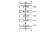
- the ECU 80 repeatedly performs the regenerative operation determination process at predetermined intervals.
- the operation determination process step S10
- the compatibility determination process step S11
- the signal determination process step S12
- the request determination process step S13
- the execution determination process step S14
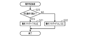
- the ECU 80 determines in the operation determination process (step S10 in FIG. 5) whether or not the regenerative operation is possible (that is, whether or not the regenerative operation can be started). (Step S20 of FIG. 6).
- the ECU 80 establishes, for example, that the vehicle is traveling (the vehicle speed is higher than “0”), that the air pressure is higher than the supply start value CI, and that the air dryer 11 is not in the supply operation. If so, it is determined that the regenerative operation is possible. On the contrary, the ECU 80 determines that at least one of the fact that the running state of the vehicle is stopped (the vehicle speed is “0”), the air pressure is equal to or higher than the regeneration threshold Cth, and the air dryer 11 is in the supply operation.
- step S20 of FIG. 6 determines that "regeneration operation is possible” (YES in step S20 of FIG. 6 )
- step S22 of FIG. 6 sets the operation flag to "FALSE" (step S22 of FIG. 6) and ends the operation determination process. ..
- the ECU 80 determines the compatibility with the regenerative operation in the compatibility determination process (step S11 in FIG. 5).
- the ECU 80 determines whether the engine is in operation (step S30 in FIG. 7). For example, the ECU 80 determines that the engine is operating based on the signal acquired from the vehicle ECU 100. Specifically, the ECU 80 determines that the engine is operating based on a signal indicating that the vehicle is traveling, a signal indicating that the vehicle is stopped, and the like. Conversely, the ECU 80 determines that the engine is not operating based on the signal indicating that the vehicle is parked.
- the ECU 80 determines whether the engine is not injecting fuel (step S31). For example, the ECU 80 determines whether or not the following first condition and second condition are satisfied based on a signal from the vehicle ECU 100, and based on that at least one of the first condition and the second condition is satisfied. It is determined that the engine is not injecting fuel.
- the first condition is related to the fuel injection amount
- the shift operation state is the non-shift operation state
- the fuel injection amount is less than or equal to the injection amount threshold
- the engine speed is greater than or equal to the rotation speed threshold. including.
- the second condition is that regardless of the fuel injection amount, the shift operation state is in the non-shift operation state, the accelerator pedal opening is less than or equal to the pedal opening threshold, and the engine torque output is less than or equal to the torque output threshold. And that the engine rotation speed is equal to or higher than the rotation speed threshold value.
- the rotation speed threshold value is a threshold value used for detecting the vehicle traveling state, and is, for example, 700 rpm.
- the pedal opening threshold value is a threshold value used for detecting an unloaded state of the engine, and is 0%, for example.
- the torque output threshold value is a threshold value used for detecting the no-load state of the engine, and is 0 Nm, for example.
- the ECU 80 determines whether or not the vehicle (speed) is decelerating (the vehicle speed is decreasing) (step S32). For example, the ECU 80 is based on the fact that at least one of the exhaust brake output being larger than the exhaust brake output threshold value and the retarder brake output being larger than the retarder brake output threshold value is established based on the signal from the vehicle ECU 100. Then, it is determined that the vehicle speed is decelerating.
- the exhaust brake output threshold value is a threshold value used for detecting a brake operating state, and is a value capable of detecting a significant brake operation, for example, 1 to 2%.
- the retarder brake output threshold value is a threshold value used for detecting a brake operating state, and is a value at which significant braking operation can be detected, for example, 1 to 2%.
- the ECU 80 also determines whether or not the vehicle speed is equal to or higher than the regenerative speed threshold (step S33). For example, the ECU 80 determines whether or not the vehicle speed is equal to or higher than the regenerable speed threshold value based on comparison of the value corresponding to the signal from the vehicle ECU 100 with the regenerable speed threshold value.
- the regenerable speed threshold is a threshold used to detect the vehicle traveling state, and is, for example, 5 km/h.
- the ECU 80 determines whether or not the air pressure of the compressed air is equal to or higher than the regenerative compatible pressure threshold value (step S34). For example, the ECU 80 determines whether or not the air pressure of the compressed air is equal to or higher than the regenerative adaptive pressure threshold value by comparing the air pressure detected by the pressure sensor 65 with the regenerative adaptive pressure threshold value.
- the regenerative adaptation pressure threshold is a value of pressure required to continue a predetermined minimum regenerative supply time, and is higher than the supply start value CI and lower than the regenerative threshold Cth, for example.
- step S34 When all the conditions of steps S30 to S34 are satisfied (YES in step S34), the ECU 80 sets the conformance flag to "TRUE" (step S35), and ends the conformity determination process. On the other hand, if the ECU 80 determines that any of the five steps S30 to S34 is not established (NO in any of the steps S30 to S34), it sets the conformance flag to "FALSE" (step S36), and determines the conformity. The process ends.
- the conformity determination process may be a process based on one or more determinations in steps S31 to S34 in FIG.
- the ECU 80 performs setting in the signal determination process (step S12 in FIG. 5) based on the signal related to the regenerative operation.
- the ECU 80 determines whether the regenerative operation is being performed (step S40 in FIG. 8).
- the ECU 80 counts the regenerative supply continuation timer (step S41).
- the ECU 80 resets the regenerative supply continuation timer (step S42).
- the ECU 80 determines whether or not the regenerative supply continuation timer is equal to or longer than a predetermined continuation time (step S43).
- the predetermined duration is the duration of the regenerative supply operation, and is set to 10 seconds, for example.
- the reception flag is set to "TRUE" (step S44), and the signal determination process ends.
- the acceptance flag is set to "FALSE" (step S45), and the signal determination process ends.
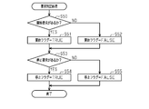
- the ECU 80 sets a start flag related to the start request determination of the regenerative operation in the request determination process (step S13 in FIG. 5).
- the ECU 80 determines whether or not there is a request to start the regenerative operation (step S50 in FIG. 9). For example, if the conditions in which the air pressure detected by the pressure sensor 65 is less than the supply stop value CO, the acceptance flag is “TRUE”, and the compatibility flag is “TRUE” are satisfied, it is determined that there is a start request. .. If there is a start request (YES in step S50), ECU 80 sets the start flag to "TRUE" (step S51). If there is no start request (NO in step S50), the ECU 80 sets the start flag to "FALSE" (step S52).
- the ECU 80 also determines whether or not there is a stop request (step S53). For example, when the start flag is “FALSE” and the operation flag is “FALSE”, the ECU 80 determines that there is a stop request. When determining that there is a stop request (YES in step S53), the ECU 80 sets the stop flag to "TRUE" (step S54), and ends the request determination process. On the other hand, when determining that there is no stop request (NO in step S53), the ECU 80 sets the stop flag to "FALSE" (step S55), and ends the request determination process.
- step S60 the ECU 80 determines whether or not to execute the regenerative supply operation in the execution determination process.
- the ECU 80 determines to execute the regenerative supply operation based on at least one of the fact that the air pressure detected by the pressure sensor 65 is equal to or less than the supply start value CI and the start flag is “TRUE”. To do. If the ECU 80 determines to execute the regenerative supply operation (YES in step S60), the ECU 80 executes the regenerative supply operation (step S61), and ends the execution determination process. On the other hand, if the ECU 80 determines not to execute the regenerative supply operation (NO in step S60), the ECU 80 does not execute the regenerative supply operation (step S62) and ends the execution determination process.
- the ECU 80 performs a stop determination process when the regenerative supply operation is being executed.
- it is determined whether to stop the regenerative supply (step S70).
- the ECU 80 determines to stop the regenerative supply based on the fact that both the air pressure detected by the pressure sensor 65 is lower than the supply stop value CO and the stop flag is “TRUE”.
- the ECU 80 stops the regenerative supply (step S71) and ends the stop determination process.
- the ECU 80 determines not to stop the regenerative supply (NO in step S70)
- the ECU 80 does not stop the regenerative supply (step S72 in FIG. 11) and ends the stop determination process.
- the compressor 4 is driven by the rotation of the engine to supply compressed air. Is executed. Regenerative supply is performed prior to the supply of compressed air by the normal supply operation, and supplements the supply of compressed air by the normal supply operation. Further, during this regenerative supply, the engine does not consume fuel for driving the compressor 4, so that the fuel efficiency of the engine can be improved.
- the present embodiment can be modified and implemented as follows.
- the present embodiment and the following modified examples can be implemented in combination with each other within a technically consistent range.
- the air tank 13 may supply the compressed air to equipment other than the brake valve 14 that consumes the compressed air, such as a parking brake.
- the pressure sensor 65 may detect the air pressure at any position downstream of the check valve 19 as long as it can detect the air pressure corresponding to the air pressure of the air tank 13.
- the pressure sensor may detect the air pressure in the air tank. Thereby, it may be possible to control the supply operation, the non-supply operation, the regeneration operation, and the regeneration operation based on the detected air pressure in the air tank.
- filter 17 has both a desiccant and a filtration part, filter 17 may have only either of them.
- filter 17 may have only either of them.
- an oil mist separator may be provided upstream of the filter 17.
- the oil mist separator includes a filter that separates gas and liquid by collision with compressed air, and captures oil contained in the compressed air sent from the compressor 4.
- the filter may be a compression molded metal material or a porous material such as sponge.
- the regenerative supply may not be started while the regeneration operation is being performed. In this way, the regeneration operation is not wasted due to the regenerative supply. In addition, the regeneration operation does not waste the regenerative supply.
- the regeneration operation may not be started while regenerative supply is being performed. For example, even if the air pressure reaches the supply stop value CO when the regenerative supply is continued for a predetermined period, the regenerating operation may not be started until the predetermined period of the regenerative supply ends. In this way, the regenerative supply is not wasted due to the regeneration operation. Further, the regeneration performance does not deteriorate due to the interruption of the regeneration operation due to the regeneration supply.
- the air supply system 10 has been described as being mounted on a vehicle such as a truck, a bus, and a construction machine.
- the air supply system may be mounted on another vehicle such as a passenger car or a railroad vehicle.
Landscapes
- Engineering & Computer Science (AREA)
- Transportation (AREA)
- Mechanical Engineering (AREA)
- Valves And Accessory Devices For Braking Systems (AREA)
- Drying Of Gases (AREA)
Abstract
L'invention concerne un système d'alimentation en air qui peut améliorer la consommation de carburant associée à l'entraînement d'un compresseur. Le système d'alimentation en air selon l'invention effectue une action d'alimentation dans laquelle de l'air comprimé fourni par un compresseur (4) est amené à s'écouler de l'amont vers l'aval par l'intermédiaire d'un dessiccateur d'air (11) qui a un filtre (17) et un clapet de non-retour (19). Le système d'alimentation en air selon l'invention est pourvu d'une unité de commande électronique, ECU, (80) qui commute entre l'action d'alimentation effectuée au niveau ou au-dessous d'une valeur de début d'alimentation et une action de non-alimentation, effectuée au niveau ou au-dessus d'une valeur d'arrêt d'alimentation, dans laquelle l'air comprimé n'est pas fourni en aval du clapet de non-retour (19) et, pendant l'action de non-alimentation, effectue une action de régénération dans laquelle le filtre (17) est régénéré. L'ECU (80) exécute une alimentation régénérative si des conditions sont satisfaites qui comprennent l'action de régénération qui n'est pas en cours, la pression d'air détectée étant supérieure à la valeur de début d'alimentation et inférieure à la valeur d'arrêt d'alimentation et un ralenti du moteur.
Priority Applications (4)
| Application Number | Priority Date | Filing Date | Title |
|---|---|---|---|
| EP19903912.4A EP3904169B1 (fr) | 2018-12-28 | 2019-12-27 | Système d'alimentation en air |
| JP2020562472A JP7420740B2 (ja) | 2018-12-28 | 2019-12-27 | 空気供給システム |
| CN201980092997.9A CN113613972B (zh) | 2018-12-28 | 2019-12-27 | 空气供给系统 |
| JP2024002267A JP7678164B2 (ja) | 2018-12-28 | 2024-01-11 | 空気供給システム |
Applications Claiming Priority (2)
| Application Number | Priority Date | Filing Date | Title |
|---|---|---|---|
| JP2018246455 | 2018-12-28 | ||
| JP2018-246455 | 2018-12-28 |
Publications (1)
| Publication Number | Publication Date |
|---|---|
| WO2020138391A1 true WO2020138391A1 (fr) | 2020-07-02 |
Family
ID=71129132
Family Applications (1)
| Application Number | Title | Priority Date | Filing Date |
|---|---|---|---|
| PCT/JP2019/051357 Ceased WO2020138391A1 (fr) | 2018-12-28 | 2019-12-27 | Système d'alimentation en air |
Country Status (4)
| Country | Link |
|---|---|
| EP (1) | EP3904169B1 (fr) |
| JP (2) | JP7420740B2 (fr) |
| CN (1) | CN113613972B (fr) |
| WO (1) | WO2020138391A1 (fr) |
Families Citing this family (3)
| Publication number | Priority date | Publication date | Assignee | Title |
|---|---|---|---|---|
| JP7224280B6 (ja) * | 2016-10-04 | 2026-02-17 | ビー1、インスティテュート、オブ、イメージ、テクノロジー、インコーポレイテッド | 画像データ符号化/復号化方法及び装置 |
| ES2988737T3 (es) | 2016-10-04 | 2024-11-21 | B1 Institute Image Technology Inc | Procedimiento y aparato de codificación/decodificación de datos de imagen |
| SE2450370A1 (en) * | 2024-04-09 | 2025-10-10 | Scania Cv Ab | Method and arrangement for removing moist in air compressor of a vehicle |
Citations (3)
| Publication number | Priority date | Publication date | Assignee | Title |
|---|---|---|---|---|
| JP2006316626A (ja) * | 2005-05-10 | 2006-11-24 | Tajima Seisakusho:Kk | 自動車のエネルギー回生装置 |
| JP2015229127A (ja) | 2014-06-03 | 2015-12-21 | 日野自動車株式会社 | エア供給システム |
| JP2018100057A (ja) * | 2016-12-21 | 2018-06-28 | ナブテスコオートモーティブ株式会社 | トレーラ用空気供給システム |
Family Cites Families (10)
| Publication number | Priority date | Publication date | Assignee | Title |
|---|---|---|---|---|
| DE19714513A1 (de) | 1997-04-08 | 1998-10-15 | Knorr Bremse Systeme | Druckluftbeschaffungsanlage für Fahrzeuge mit einer Einrichtung zum Erkennen von Schubphasen |
| ITMI20032156A1 (it) * | 2003-11-10 | 2005-05-11 | Iveco Spa | Mertodo e dispositivo di controllo della regolazione, essiccazione e rigenerazione di un gruppo regolatore-essicatore di un sistema pneumatico o pneumoidraulico di frenatura di un veicolo. |
| DE102006035772A1 (de) * | 2006-08-01 | 2008-02-07 | Wabco Gmbh | Druckluftversorgungseinrichtung für Kraftfahrzeuge |
| JP4985458B2 (ja) * | 2008-02-20 | 2012-07-25 | 日産自動車株式会社 | アイドルストップ車両の回生制御装置 |
| DE102008056322A1 (de) * | 2008-11-07 | 2010-05-12 | Wabco Gmbh | Steuereinrichtung für eine Druckluftaufbereitungseinrichtung eines Fahrzeuges, Druckluftaufbereitungseinrichtung sowie Verfahren zu deren Steuerung |
| DE102009017903A1 (de) | 2009-04-17 | 2010-10-21 | Knorr-Bremse Systeme für Nutzfahrzeuge GmbH | Druckluftversorgungssystem für ein Kraftfahrzeug |
| DE102010018949A1 (de) * | 2010-04-30 | 2011-11-03 | Wabco Gmbh | Druckluftaufbereitungseinrichtung, Druckluftversorgungssystem mit einer Druckluftaufbereitungseinrichtung und Aufbereitungsmodul hierfür sowie Verfahren zum Betrieb einer Druckluftaufbereitungseinrichtung, Steuermodul und Fahrzeug mit einer Druckluftaufbereitungseinrichtung |
| DE102012021597B4 (de) * | 2012-11-02 | 2024-02-22 | Zf Cv Systems Hannover Gmbh | Verfahren zur Druckluftaufbereitung in Kraftfahrzeugen und Einrichtung zur Durchführung dieses Verfahrens |
| DE102013000275A1 (de) * | 2013-01-09 | 2014-07-10 | Wabco Gmbh | Verfahren und Vorrichtung zur Steuerung einer Druckluft-Bremsanlage eines Fahrzeuggespanns |
| JP6700174B2 (ja) * | 2014-05-09 | 2020-05-27 | ナブテスコオートモーティブ株式会社 | 圧縮空気乾燥装置、圧縮空気乾燥装置の制御方法及び車両 |
-
2019
- 2019-12-27 WO PCT/JP2019/051357 patent/WO2020138391A1/fr not_active Ceased
- 2019-12-27 JP JP2020562472A patent/JP7420740B2/ja active Active
- 2019-12-27 CN CN201980092997.9A patent/CN113613972B/zh active Active
- 2019-12-27 EP EP19903912.4A patent/EP3904169B1/fr active Active
-
2024
- 2024-01-11 JP JP2024002267A patent/JP7678164B2/ja active Active
Patent Citations (3)
| Publication number | Priority date | Publication date | Assignee | Title |
|---|---|---|---|---|
| JP2006316626A (ja) * | 2005-05-10 | 2006-11-24 | Tajima Seisakusho:Kk | 自動車のエネルギー回生装置 |
| JP2015229127A (ja) | 2014-06-03 | 2015-12-21 | 日野自動車株式会社 | エア供給システム |
| JP2018100057A (ja) * | 2016-12-21 | 2018-06-28 | ナブテスコオートモーティブ株式会社 | トレーラ用空気供給システム |
Also Published As
| Publication number | Publication date |
|---|---|
| CN113613972B (zh) | 2024-03-29 |
| EP3904169A1 (fr) | 2021-11-03 |
| JP7678164B2 (ja) | 2025-05-15 |
| CN113613972A (zh) | 2021-11-05 |
| JPWO2020138391A1 (ja) | 2021-11-04 |
| JP7420740B2 (ja) | 2024-01-23 |
| JP2024026707A (ja) | 2024-02-28 |
| EP3904169B1 (fr) | 2023-09-20 |
| EP3904169A4 (fr) | 2022-10-26 |
Similar Documents
| Publication | Publication Date | Title |
|---|---|---|
| JP7678164B2 (ja) | 空気供給システム | |
| JP2025015842A (ja) | 空気供給システム、空気供給システムの制御方法、及び空気供給システムの制御プログラム | |
| JP2020105989A (ja) | 空気供給システム | |
| JP7497477B2 (ja) | 空気供給システム | |
| JP2023165731A (ja) | 空気供給システムの制御方法 | |
| JP7476111B2 (ja) | 空気供給システム | |
| JP7736850B2 (ja) | 空気供給システム、空気供給システムの制御方法、及び空気供給システムの制御プログラム | |
| JP7263049B2 (ja) | 空気供給システム及び空気供給システムの制御方法 | |
| JP7629971B2 (ja) | 空気供給システム | |
| JP7476110B2 (ja) | 空気供給システム | |
| JP7226992B2 (ja) | 空気供給システム | |
| JP7436388B2 (ja) | 空気供給システム |
Legal Events
| Date | Code | Title | Description |
|---|---|---|---|
| 121 | Ep: the epo has been informed by wipo that ep was designated in this application |
Ref document number: 19903912 Country of ref document: EP Kind code of ref document: A1 |
|
| ENP | Entry into the national phase |
Ref document number: 2020562472 Country of ref document: JP Kind code of ref document: A |
|
| NENP | Non-entry into the national phase |
Ref country code: DE |
|
| ENP | Entry into the national phase |
Ref document number: 2019903912 Country of ref document: EP Effective date: 20210728 |