WO2020138531A1 - Étau à angle réglable - Google Patents
Étau à angle réglable Download PDFInfo
- Publication number
- WO2020138531A1 WO2020138531A1 PCT/KR2018/016705 KR2018016705W WO2020138531A1 WO 2020138531 A1 WO2020138531 A1 WO 2020138531A1 KR 2018016705 W KR2018016705 W KR 2018016705W WO 2020138531 A1 WO2020138531 A1 WO 2020138531A1
- Authority
- WO
- WIPO (PCT)
- Prior art keywords
- gear
- angle
- mounting
- adjustable angle
- vise
- Prior art date
- Legal status (The legal status is an assumption and is not a legal conclusion. Google has not performed a legal analysis and makes no representation as to the accuracy of the status listed.)
- Ceased
Links
Images


Classifications
-
- B—PERFORMING OPERATIONS; TRANSPORTING
- B23—MACHINE TOOLS; METAL-WORKING NOT OTHERWISE PROVIDED FOR
- B23K—SOLDERING OR UNSOLDERING; WELDING; CLADDING OR PLATING BY SOLDERING OR WELDING; CUTTING BY APPLYING HEAT LOCALLY, e.g. FLAME CUTTING; WORKING BY LASER BEAM
- B23K37/00—Auxiliary devices or processes, not specially adapted for a procedure covered by only one of the other main groups of this subclass
- B23K37/04—Auxiliary devices or processes, not specially adapted for a procedure covered by only one of the other main groups of this subclass for holding or positioning work
- B23K37/0426—Fixtures for other work
- B23K37/0452—Orientable fixtures
-
- B—PERFORMING OPERATIONS; TRANSPORTING
- B23—MACHINE TOOLS; METAL-WORKING NOT OTHERWISE PROVIDED FOR
- B23K—SOLDERING OR UNSOLDERING; WELDING; CLADDING OR PLATING BY SOLDERING OR WELDING; CUTTING BY APPLYING HEAT LOCALLY, e.g. FLAME CUTTING; WORKING BY LASER BEAM
- B23K37/00—Auxiliary devices or processes, not specially adapted for a procedure covered by only one of the other main groups of this subclass
- B23K37/04—Auxiliary devices or processes, not specially adapted for a procedure covered by only one of the other main groups of this subclass for holding or positioning work
-
- B—PERFORMING OPERATIONS; TRANSPORTING
- B25—HAND TOOLS; PORTABLE POWER-DRIVEN TOOLS; MANIPULATORS
- B25B—TOOLS OR BENCH DEVICES NOT OTHERWISE PROVIDED FOR, FOR FASTENING, CONNECTING, DISENGAGING OR HOLDING
- B25B1/00—Vices
- B25B1/02—Vices with sliding jaws
-
- B—PERFORMING OPERATIONS; TRANSPORTING
- B25—HAND TOOLS; PORTABLE POWER-DRIVEN TOOLS; MANIPULATORS
- B25B—TOOLS OR BENCH DEVICES NOT OTHERWISE PROVIDED FOR, FOR FASTENING, CONNECTING, DISENGAGING OR HOLDING
- B25B1/00—Vices
- B25B1/06—Arrangements for positively actuating jaws
- B25B1/10—Arrangements for positively actuating jaws using screws
-
- B—PERFORMING OPERATIONS; TRANSPORTING
- B25—HAND TOOLS; PORTABLE POWER-DRIVEN TOOLS; MANIPULATORS
- B25B—TOOLS OR BENCH DEVICES NOT OTHERWISE PROVIDED FOR, FOR FASTENING, CONNECTING, DISENGAGING OR HOLDING
- B25B1/00—Vices
- B25B1/22—Arrangements for turning or tilting vices
Definitions
- the present invention relates to an adjustable angle vise that is a fixing device capable of performing work requiring assembly and welding between materials at a fixed position by setting a specific angle and pipe notching, more specifically
- the angle is set by using the displacement angle of the circumscribed gear that is rotated by driving, and the material can be fixed using a step clamp and a binding device attached to the extension plane of the circumscribed gear.
- An angle confirmation window is provided to confirm the setting of the protractor and the angle, and it is possible to actively respond to accurate and intuitive confirmation and change of the setting angle, and to implement various types of finished products and work ranges by implementing a wide range of configurable angles. It relates to an adjustable angle vice for the purpose of providing operator convenience due to efficient utilization.
- the assembly and welding work of the finished product is performed by binding the material with a fixed clamp, a vise in the form of moving in a single straight line on a plane, and an angle-fixed and angle-adjustable angle vise using two axes intersecting on the plane. It has been.
- angle vices are used to bind the material by using a jaw in the form of a fixed angle and an angle block, such as 22.5', 45', 90', 135', .., etc.
- traffic facilities such as bus stops, guide signs, and blocking installations, which are welded structures using structural steel such as square pipes or steel pipes, and bicycle storage and
- public facilities such as park chairs, indoor and outdoor furniture in office and residential facilities, indoor and outdoor advertisements, and sculptures based on personal hobbies and plans.
- the pipe notching operation involves laser processing and the holding and outsourcing of hydraulic/pneumatic notching equipment, and the pipe notcher is limited to its usefulness as a work tool for a single purpose.
- the completeness of the result is low during gas cutting and polishing, and it takes a lot of time for processing.
- the technical problem to be achieved by the present invention is to accurately and intuitively check the angle that can be set to respond more flexibly to the field situation, and to allow active deployment and binding between release materials, and the jamming phenomenon due to the difference in length between materials.
- the purpose of this is to provide the convenience of the operator and the construction of various types of finished products and the uniform quality by expanding the scope of use by eliminating and eliminating the need for the tubular material.
- the adjustable angle vise of the present invention is geared to form an angle by utilizing an extent that is rotated by driving in engagement with the gear 1 surface 100, gear 2 surface 110 and;
- a protractor set 120 and an angle confirmation window 130 provided on the upper surfaces of the gear 1 surface 100 and the gear 2 surface 110 to accurately and intuitively check the displacement and setting of the angle;
- the mounting 1 surface 140 and mounting 2 surface 150 are individually assigned to fasten the binding between release materials and various types of fastening devices, and thus the step clamp 400 and the binding device transfer table 440A capable of movement adjustment are attached.
- the step clamp 400 and the binding device transfer table 440A capable of movement adjustment are attached.
- the side projections of the mounting 1 surface 140 and the mounting 2 surface 150 include a vertical holder 500 provided to secure a fixing criterion during vertical development corresponding to a plane;
- a seating groove that includes a central axis of the gear 1 surface 100 and the gear 2 surface 110 and is capable of detaching the device fastening part 330 and the ball fixing method ball B formed to be fastened to a workbench or equipment. It provides an adjustable angle vise, characterized in that consisting of a gear fixing part (320) is formed.
- the ball fixing method ball (B) and the spring (S) are formed to form a ball fixing internal part 520 to move up and down, thereby fixing the gear. It is preferable that the ball B is selectively detached from the seating groove 320 provided in 300. In addition, it is preferable that an adjusting bolt W for adjusting the elastic force of the spring S is provided at the upper end of the ball fixing inner portion 520.
- the gear 1 surface 100, the gear 2 surface 110 and the relative surfaces of the gear fixing part 300 have a friction plate 220 and a gear 1 surface 100 for securing wear resistance due to friction generated in driving rotation. ), on the central axis where the gear 2 surface 110 and the gear fixing part 300 are linked, insert the fixing bushing 210 to correct the clearance generated during rotation expansion and fixation, and quickly constrain the set angle of the device. Decision making is preferably provided with a fixed handle (200).
- the adjustable angle vise according to the present invention provides the following effects.
- the adjustable angle vise of the present invention can be rotated and unfolded on a plane
- the purpose of use of the adjustable angle vise that is, the angle set for the purpose of use such as assembly and welding work through the maintenance of fixing between materials
- the adjustable angle vise of the present invention has a protractor set 120 and an angle confirmation window 130 to accurately and intuitively check the change and setting of the angle on the gear 1 side 100 and the gear 2 side 110. Since it does not require the use of additional measurement tools, it has the effect of providing speed, accuracy and convenience of angle setting work.
- the adjustable angle vise of the present invention is a gear 1 surface 100, the gear 2 surface 110 and the gear fixing part 300, which are rotationally deployed, and the detachable ball fixing inner part 520 and the seating groove 320.
- the adjustable angle vice of the present invention by placing the step clamp 400 that can be linearly moved on the mounting 1 surface 140 and mounting 2 surface 150 individually, eliminates the jamming phenomenon due to the difference in length between materials at the same angle, It has the effect of realizing various tasks by having structural characteristics that can selectively engage various types of engagement devices or pipe notchers that can secure the centers of circles and polygons.
- adjustable angle vise of the present invention has the effect of simplifying the structure, so that it is easy to operate and various angles are configurable to obtain various types of creative finished products.
- FIG. 1 is a combined perspective view showing the outer shape of the adjustable angle vise according to the present invention.
- FIG. 2 is an exploded perspective view showing an assembled state of the protractor set 120 and the angle confirmation window 130 of the adjustable angle vise according to the present invention.
- FIG 3 is an exploded perspective view showing an assembled state of the gear 1 surface 100, the gear 2 surface 110, the mounting 1 surface 140, and the mounting 2 surface 150 of the adjustable angle vise according to the present invention.
- FIG 4 is an enlarged perspective view of the protractor set 120 and the angle confirmation window 130 of the adjustable angle vise according to the present invention.
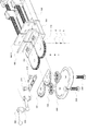
- FIG 5 is a perspective view showing a gear fixing part 300 of an adjustable angle vise according to the present invention.
- FIG. 6 is a perspective view showing the structure of a mounting angle side vise according to the present invention, such as the mounting surface 1, 140, mounting surface 2 150 and step clamp 400.
- FIG. 7 is an exemplary view showing the driving and rotational development of the adjustable angle vise according to the present invention.
- Figure 8 is an exemplary view showing the vertical deployment function of the adjustable angle vice according to the present invention.
- FIG. 9 is an exploded perspective view showing the configuration and assembly state of the pipe notch of the adjustable angle vise according to the present invention.
- FIG. 10 is an exemplary view showing a pipe notching function of the adjustable angle vise according to the present invention.
- the adjustable angle vise is gear 1 side 100 and gear 2 side 110, a pair of facing protractor sets 120 and an angle confirmation window 130, mounting 1 side 140 and mounting 2 side 150 ), step clamp 400 and binding device (440A/B), gear fixing part 300 and vertical fixture 500, central shaft 310, fixing bushing 210 and friction plate 220 as fixing members, fixing It is composed of a handle bolt 230, a fixing handle 200 and a bolt, a nut, which is a connecting member.
- Each gear 1 surface 100 and gear 2 surface 110 are rotated by being engaged with respect to two parallel central shafts 310 of the gear fixing part 300, and rotated, and the step clamp 400 in a fixed alignment position )
- the step clamp 400 Refers to the part formed in the form of a circumscribed gear.
- the first surface 140 and the second surface 150 which are the extended planes of the gear 1 surface 100 and the gear 2 surface 110, are formed so that the material can be disposed. And it is composed of structural features that can be fastened, such as a binding device (440A / B) that can be fixed.
- the concept is to set the angle by utilizing and use the step clamp 400 and the binding device 440A/B that are individually assigned to the mounting 1 surface 140 and mounting 2 surface 150 to bind the material.
- the gear 1 surface 100 and the gear 2 surface 110 have a form of a circumscribed gear in which a pitch circle circumscribes and meshes with respect to two parallel central axes 310 of the gear fixing part 300, and the binding of the material
- the angles of the states in which the two side clamps 400 aligned at fixed positions are parallel to each other and the sides of the mounting 1 surface 140 and mounting 2 surface 150, which are the extended planes for the "machine,” 0 degrees".
- the upper side of the gear 1 surface 100 and the gear 2 surface 110 is directed to a pitch circle circumscribed from each central axis 310, corresponds to the rotation of the pitch circle, and is indicated by dividing the leader line and the number at an equal angle. It is provided with a pair of protractor sets 120 to actively cope with the intuitive confirmation and change of the angle to be set.
- the notation of the angle indicator and the number of the protractor set 120 is based on “mechanical 0 degree”, and the central axis 310 and the pitch circle of the gear 1 side 100 and the gear 2 side 110 are different.
- the angle formed by the corresponding protractor set 120 when in a straight line in contact is set to 0 degrees, and the actual notation is set to 180 degrees. The reason for this is because the angle at which the material is engaged in a straight line between the step clamp 400 and the binding device 440A/B when it is "mechanical 0 degree” is 180 degrees.
- the notation of the indicator lines and numbers of the angle is the case of the gear 1 surface 100, for example, to limit the notation from the circumscribed point of the pitch circle to 180 degrees clockwise, and the position of -90 degrees from the circumscribed point of the pitch circle.
- marking "Actual 0 degree” mark the leader and the number by dividing them evenly symmetrically, but the interval between the angle indicators is 5 degrees, and the number of angle values is arranged in 15-degree units of the angle indicator.
- the reference unit of the angle indicator is 5 degrees, but in order to cause displacement to the corresponding angle, the gear 1 surface 100 and the gear 2 surface 110 correspond to the circumference of the pitch circle and each central axis 310. Therefore, if the displacement occurs every 2.5 degrees, it can be confirmed from the structural characteristic that utilizes the angle of the range to be driven by driving.
- an angle confirmation window 130 capable of confirming the change and setting of the angle according to the rotation of the gear 1 surface 100 and the gear 2 surface 110 is provided, but the gear 1 surface 100 and the gear 2 surface 110 are provided.
- the two parallel central axes 310 and the pitch circle are provided in a straight line circumscribed
- the dimensional notation of the above-mentioned dividing angle is for understanding, and it is exemplified by applying a typical setting angle frequently used in the production of actual finished products, and it is stated that the dimension can be rearranged by varying the number of teeth of the module and the gear.
- Mounting 1 surface 140 and mounting 2 surface 150 refer to portions of the extended plane excluding gear 1 surface 100 and gear 2 surface 110 based on step clamp 400 in a fixed alignment position. And it can be seen that the step clamp 400 for binding the material, the binding device 440A/B, and the vertical fixture 500 performing a vertical deployment function are provided.
- each of the mounting surface 1 140 and mounting surface 2 150 forms a linear slide groove 530 penetrating the central portion to form a step clamp 400 for binding the material and a binding device transfer table 440A.
- a linear slide groove 530 penetrating the central portion to form a step clamp 400 for binding the material and a binding device transfer table 440A.
- the fastening bolts 420 may be moved from an aligned position to a horizontal surface on which the step clamps 400 of the respective mounting 1 surface 140 and mounting 2 surface 150 are located to be fixed and released at a selective position. It is provided. The reason for this is to secure the space of the binding position at the same angle when binding between the materials after the setting restraint is completed at the specified angle and to eliminate the jamming phenomenon due to the length difference between the materials.
- the vertical clamping device 400 and the clamping unit 470A are formed on the vertical surfaces of the step clamp 400 and the binding device transfer table 440A to notch the clamping device and the tubular material to secure the center point of the material having a circular or polygonal cross section. It is possible to selectively fasten the pipe notch, etc. to perform the.
- the vertical fixture 500 when the vertical fixture 500 is described, it is provided at the bottom of the protrusions, which are the same sides of the mounting 1 surface 140 and the mounting 2 surface 150, and the adjustable angle vise rotates and develops even in a vertical state corresponding to the plane. It plays a role to ensure that the standard is secured.
- the vertical fixture 500 is a gear fixing part 300 in the outline of the right protrusion of the mounting 2 surface 150 when the adjustable angle vice is mechanical 0 degrees.
- a tangent line is formed.
- Such a tangent comprises a continuous tangent along the circumference (circle) of the outline of the gear fixing part 300 along with rotation of the mounting 2 surface 150 to secure the mounting 2 surface 150 in a vertical position on the plane.
- the table is made of steel, and the vertical holder 500 is assumed to be a strong magnet, and when the adjustable angle vice is vertically positioned on the table, the protrusion 2 and the gear fixing part 300 of the mounting 2 surface 150 are formed. It is possible to secure a fixed criterion in which the tangent line is in horizontal contact with the table, and the mounting 1 surface 140 and the gear fixing part 300 can be rotated and developed based on the mounting 2 surface 150 fixed to the table. Those of ordinary skill in the art can easily understand.
- the gear fixing part 300 is located at the lower end of the gear 1 surface 100 and the gear 2 surface 110 which are engaged, and the gear 1 surface 100 and the gear 2 surface 110 are located on two parallel central axes 310. ) A through hole is formed so that it can be fastened by using the fixing handle bolt 230 and the fixing handle 200 to serve as a reference for the rotation axis of the gear 1 surface 100 and the gear 2 surface 110.
- the ball B of the ball fixing internal part 520 of the gear 1 surface 100 and the gear 2 surface 110 and the seating groove 320 of the gear fixing part 300 are linked to each other. It can be confirmed that it is functional.
- the diameter of the seating groove 320 provided in the gear fixing part 300 is processed to a dimension of about 70% of the ball fixing internal parts 520 formed on the gear 1 surface 100 and the gear 2 surface 110 to be detached.
- the incoming and outgoing of the ball (B) is made to function smoothly.
- the pitch of the screw is M4*0.7P
- the ball fixing recess 520 formed on the gear 1 surface 100 and the gear 2 surface 110 has an actual inner diameter of 3.3 mm and a diameter of the ball B. Assuming 3.0mm.
- the ratio of the ball (B) introduced into the seating groove 320 of the gear fixing part 300 is configured to be 3:1 so that the wear-resistance of the gear fixing part 300 can be increased and a stable fixing function can be performed when detaching. do.
- the gear is used using a fixed bushing 210, which is one type of lubrication-free bearing having excellent lubricity and wear resistance. It connects from the central axis of the one surface 100 and the second surface 110 to each central axis 310 formed in the gear fixing part 300. At this time, by vertically pressing to prevent eccentricity, the restraint of the central axis 310 is secured to have a function of correcting the clearance generated during driving rotation of the gear 1 surface 100 and the gear 2 surface 110.
- a friction plate 220 conforming to the dimension of about 0.02 to 0.05 mm is disposed to minimize the friction of the opposite surface and durability.
- the clamp lever nut which is the fixing handle 200 is a device for quickly binding the gear 1 surface 100, the gear 2 surface 110, and the gear fixing part 300, the lower surface of the gear fixing part 300 It is fastened by using a fixed handle bolt 230 penetrating from the top surface of each of the gear 1 surface 100 and the gear 2 surface 110 to the extended plane of the gear 1 surface 100 and the gear 2 surface 110 In order to avoid interference with the step clamp 400 provided in and to have a function to be selectively fastened in various directions.
- the adjustable hanger vise of the present invention has a structural feature capable of direct processing work in addition to the function as a fixing device of a material by mounting a pipe notcher capable of performing notching work of a tubular material.
- case unit 600 linear bushing 610, linear shaft 620, spindle shaft 630, ball bearing 640A, snap ring 640C, spindle It consists of a structure such as a lock guide rail 680 and guide 660.
- the jaw fixing part 650 is formed, and includes a linear bushing 610 capable of linear and rotational motion.
- the linear bushing 610 serves to induce the linear shaft 620 to reach the material to be processed.
- a spindle lock guide rail 680 is formed in the longitudinal direction on the outside of the linear shaft 620 to face the spindle lock guide 660 that suppresses rotational motion, and only linear motion is possible. Actual rotation is linear shaft.
- the spindle shaft 630 is in charge of the bearing 640A installed on both sides of the 620 as a main axis. This is because it is an essential safety factor to prevent a pinching or curling disaster that may occur from the rotation of the linear shaft 620 protruding to the outside to reach the workpiece.
- the adjustable angle vise of the present invention provides the convenience of operation due to the quick and accurate setting of the angle and structural characteristics, and allows the binding between the release materials, the notching of the tubular material, and the development in the vertical direction. In addition to the vise's original function and purpose of use, it can be used more widely.
- the adjustable angle vise according to the present invention is based on the structure of an intuitive and simplified operation type, so that the user's convenience is prioritized, and various types of operating ranges are utilized to obtain various types of creative, stable, and repetitive results.
- gear 1 side 110 gear 2 side
- protractor set 130 angle confirmation window 140: mounting 1 side 150: mounting 2 side
- gear fixing part 310 central axis 320: seating groove 330: device fastening part
- Step clamp 410 Step clamp fixing washer 420: Step clamp fixing bolt
- binding unit transfer base 440B binding unit fixing unit 450: slide rail fixing washer
- slide groove 540 slide rail
Landscapes
- Engineering & Computer Science (AREA)
- Mechanical Engineering (AREA)
- Physics & Mathematics (AREA)
- Optics & Photonics (AREA)
- Gripping Jigs, Holding Jigs, And Positioning Jigs (AREA)
Abstract
La présente invention concerne un étau à angle réglable qui est un appareil de fixation susceptible de réaliser une opération nécessitant un assemblage et un soudage entre des matériaux et un entaillage de tuyau d'un matériau tubulaire à une position fixe et à un angle particulier prédéfini et, plus particulièrement, un étau à angle réglable comprenant : une première surface d'engrenage (100) et une seconde surface d'engrenage (110), qui sont entraînées en rotation et entre lesquelles un angle de déplacement déployé est utilisé pour régler un angle ; une pince à pas (400) et un appareil de liaison (440A/B) qui sont montés sur une première surface de montage (140) et une seconde surface de montage (150) et sont utilisés pour fixer un matériau ; une paire d'ensembles de rapporteur (120) sur lesquels des lignes d'indication d'angle correspondantes sont marquées ; une fenêtre de confirmation d'angle (130) à travers lequel le réglage d'un angle peut être identifié pour permettre une identification exacte et intuitive d'un angle réglé et une réaction active à un changement de l'angle réglé ; et une table de fixation verticale (500) qui permet à l'étau à angle réglable de se déployer perpendiculairement à un plan. L'étau à angle réglable a des plages de mise en œuvre de diverses manières d'un angle réglable et permet ainsi l'acquisition de divers types de produits finis et l'utilisation efficace d'une plage de fonctionnement et fournit une commodité à un travailleur.
Applications Claiming Priority (3)
| Application Number | Priority Date | Filing Date | Title |
|---|---|---|---|
| KR20170183263 | 2017-12-29 | ||
| KR1020180168069A KR102148580B1 (ko) | 2017-12-29 | 2018-12-24 | 조절형 앵글 바이스 및 이를 이용하는 파이프노쳐 |
| KR10-2018-0168069 | 2018-12-24 |
Publications (1)
| Publication Number | Publication Date |
|---|---|
| WO2020138531A1 true WO2020138531A1 (fr) | 2020-07-02 |
Family
ID=67261948
Family Applications (1)
| Application Number | Title | Priority Date | Filing Date |
|---|---|---|---|
| PCT/KR2018/016705 Ceased WO2020138531A1 (fr) | 2017-12-29 | 2018-12-27 | Étau à angle réglable |
Country Status (2)
| Country | Link |
|---|---|
| KR (1) | KR102148580B1 (fr) |
| WO (1) | WO2020138531A1 (fr) |
Cited By (2)
| Publication number | Priority date | Publication date | Assignee | Title |
|---|---|---|---|---|
| CN115539777A (zh) * | 2022-09-05 | 2022-12-30 | 中铁高新工业股份有限公司 | 一种盾构法隧道用可角度定位的通信抱杆安装架 |
| CN115971777A (zh) * | 2023-03-21 | 2023-04-18 | 山西中部智造科技有限公司 | 一种基于bim的钢结构梁焊接用定位装置 |
Families Citing this family (4)
| Publication number | Priority date | Publication date | Assignee | Title |
|---|---|---|---|---|
| CN111532009A (zh) * | 2020-06-17 | 2020-08-14 | 京东方科技集团股份有限公司 | 柔性屏的贴合治具和柔性屏的贴合方法 |
| CN112355555B (zh) * | 2021-01-13 | 2021-04-30 | 迈赫机器人自动化股份有限公司 | 一种便于调节角度的焊接工装 |
| CN114083127B (zh) * | 2022-01-19 | 2022-04-15 | 铭镭激光智能装备(河源)有限公司 | 一种可翻转式激光焊接机夹紧机构及其工作方法 |
| KR102902988B1 (ko) * | 2024-02-06 | 2025-12-19 | 한남대학교 산학협력단 | 자작 전기자동차의 용접용 지그 프레임 |
Citations (6)
| Publication number | Priority date | Publication date | Assignee | Title |
|---|---|---|---|---|
| US4418901A (en) * | 1981-04-22 | 1983-12-06 | International Design Corporation | Vise system |
| US4953839A (en) * | 1989-09-28 | 1990-09-04 | Chern Sen Kuen | Vise |
| KR200191364Y1 (ko) * | 1999-11-26 | 2000-08-16 | 류인일 | 공구연마대 |
| CN102001060A (zh) * | 2009-09-02 | 2011-04-06 | 铜陵市永生机电制造有限责任公司 | 一种可调倾角的台钳 |
| US8152419B1 (en) * | 2008-11-25 | 2012-04-10 | Holly R Snyder | Tubular member notching system and method |
| US20120243954A1 (en) * | 2011-03-23 | 2012-09-27 | Rusch Christopher J | Hole saw tube notcher |
-
2018
- 2018-12-24 KR KR1020180168069A patent/KR102148580B1/ko active Active
- 2018-12-27 WO PCT/KR2018/016705 patent/WO2020138531A1/fr not_active Ceased
Patent Citations (6)
| Publication number | Priority date | Publication date | Assignee | Title |
|---|---|---|---|---|
| US4418901A (en) * | 1981-04-22 | 1983-12-06 | International Design Corporation | Vise system |
| US4953839A (en) * | 1989-09-28 | 1990-09-04 | Chern Sen Kuen | Vise |
| KR200191364Y1 (ko) * | 1999-11-26 | 2000-08-16 | 류인일 | 공구연마대 |
| US8152419B1 (en) * | 2008-11-25 | 2012-04-10 | Holly R Snyder | Tubular member notching system and method |
| CN102001060A (zh) * | 2009-09-02 | 2011-04-06 | 铜陵市永生机电制造有限责任公司 | 一种可调倾角的台钳 |
| US20120243954A1 (en) * | 2011-03-23 | 2012-09-27 | Rusch Christopher J | Hole saw tube notcher |
Cited By (2)
| Publication number | Priority date | Publication date | Assignee | Title |
|---|---|---|---|---|
| CN115539777A (zh) * | 2022-09-05 | 2022-12-30 | 中铁高新工业股份有限公司 | 一种盾构法隧道用可角度定位的通信抱杆安装架 |
| CN115971777A (zh) * | 2023-03-21 | 2023-04-18 | 山西中部智造科技有限公司 | 一种基于bim的钢结构梁焊接用定位装置 |
Also Published As
| Publication number | Publication date |
|---|---|
| KR20190082104A (ko) | 2019-07-09 |
| KR102148580B1 (ko) | 2020-08-26 |
Similar Documents
| Publication | Publication Date | Title |
|---|---|---|
| WO2020138531A1 (fr) | Étau à angle réglable | |
| CN102554631B (zh) | 组合夹具集成平台 | |
| US8172234B2 (en) | Collet tool holder having adjustable axis | |
| US7094012B1 (en) | Quick set-up tilt table | |
| BR0002727A (pt) | Dispositivo para fixar uma peça de trabalho | |
| JP2005169537A (ja) | ワークの位置決め固定冶具 | |
| CN214519000U (zh) | 一种用于龙门机床加工中心的环形工件定位夹紧工装 | |
| CN111408966B (zh) | 一种汽车曲轴中心孔cnc加工钻孔定位模具 | |
| CN217252916U (zh) | 一种多爪同心卡盘用可调节夹具 | |
| CN211939114U (zh) | 一种钻床夹具 | |
| JP2004098201A (ja) | 角度固定装置、該装置を備えた加工装置、及び角度固定方法 | |
| CN119501635A (zh) | 一种轴承座加工夹具 | |
| CN220279398U (zh) | 一种汽车配件加工用定位装置 | |
| CN218556754U (zh) | 一种夹持装置 | |
| CN219131558U (zh) | 一种cnc数控机床的夹具用快速定位机构 | |
| US827062A (en) | Combined drill-block and bench-block. | |
| CN113070709B (zh) | 一种加工中心四轴转台夹具用具有自锁机构的固定装置 | |
| CN212735115U (zh) | 一种定位夹具 | |
| CN213968530U (zh) | 钢管高精度冲弧成型工艺装置 | |
| CN210210061U (zh) | 一种机械加工用台钳 | |
| CN222059534U (zh) | 一种碰撞锁止装置旋转工装 | |
| CN121624717B (zh) | 一种焊接工装及其焊接方法 | |
| CN223406488U (zh) | 圆虎钳可调式通用工装底板 | |
| CN110919415A (zh) | 多角度旋转台钳 | |
| CN223588352U (zh) | 一种轴承车加工用夹具工装 |
Legal Events
| Date | Code | Title | Description |
|---|---|---|---|
| 121 | Ep: the epo has been informed by wipo that ep was designated in this application |
Ref document number: 18945016 Country of ref document: EP Kind code of ref document: A1 |
|
| NENP | Non-entry into the national phase |
Ref country code: DE |
|
| 122 | Ep: pct application non-entry in european phase |
Ref document number: 18945016 Country of ref document: EP Kind code of ref document: A1 |