WO2020144492A1 - Générateur à cycle combiné à rendement de 100 % - Google Patents
Générateur à cycle combiné à rendement de 100 % Download PDFInfo
- Publication number
- WO2020144492A1 WO2020144492A1 PCT/IB2019/050091 IB2019050091W WO2020144492A1 WO 2020144492 A1 WO2020144492 A1 WO 2020144492A1 IB 2019050091 W IB2019050091 W IB 2019050091W WO 2020144492 A1 WO2020144492 A1 WO 2020144492A1
- Authority
- WO
- WIPO (PCT)
- Prior art keywords
- generator
- coils
- fixed
- outer shell
- motor
- Prior art date
- Legal status (The legal status is an assumption and is not a legal conclusion. Google has not performed a legal analysis and makes no representation as to the accuracy of the status listed.)
- Ceased
Links
Images


Classifications
-
- H—ELECTRICITY
- H02—GENERATION; CONVERSION OR DISTRIBUTION OF ELECTRIC POWER
- H02K—DYNAMO-ELECTRIC MACHINES
- H02K21/00—Synchronous motors having permanent magnets; Synchronous generators having permanent magnets
- H02K21/12—Synchronous motors having permanent magnets; Synchronous generators having permanent magnets with stationary armatures and rotating magnets
-
- H—ELECTRICITY
- H02—GENERATION; CONVERSION OR DISTRIBUTION OF ELECTRIC POWER
- H02K—DYNAMO-ELECTRIC MACHINES
- H02K7/00—Arrangements for handling mechanical energy structurally associated with dynamo-electric machines, e.g. structural association with mechanical driving motors or auxiliary dynamo-electric machines
- H02K7/20—Structural association with auxiliary dynamo-electric machines, e.g. with electric starter motors or exciters
Definitions
- the combined cycle generator with 100% efficiency has an F01 international classification.In the area of energy, there are problems such as heavy costs of generating energy and the lack of access to unlimited resources and the use of renewable energy is not always possible.
- This generator consists of two fixed and moving parts. The fixed part involves the cores and wires, while the moving part of the generator contains the outer shell. The components of this generator include 48 magnet magnets, compact plastics, electromagnetic coils, outer shell, and two shafts and ball bearings. The rotor is constant in this generator and the crust (shell) rotates around the rotor, which can generate more power with lower engine speed (RPM) compared to electric power generation similar generators.
- RPM engine speed
- This device can be used at combined cycle power plants or at any kind of power plants. It can be also utilized in agriculture, industry, home applications, electric cars, factories, and especially in areas far from the power grid.
- the counterclockwise rotor axial flux generator system is made up of 4 main parts of the first rotor, the second rotor, a stator, and a frame.
- the first rotor is consisted of bars radially arranged together by a metallic ring within the ring as short circuit and a half-axis is attached vertically to its center as its axis.
- the second rotor is like a disk that is split on both sides and two three-phase coils are wrapped on both its sides.
- the generator frame task is to keep the two rotors fixed so that they rotate slightly in the opposite direction of each other.
- the stator is connected to the main body and is responsible for receiving the electric energy produced in the second rotational rotor through induction and transferring it to its outlet terminals. This stator frees the generator from the need for brushless and the sliding ring.
- a capacitive bank will be connected to the output with the task of controlling the voltage and creating the field for the second rotor.
- Gravity-based generator for generating electricity using a generator
- the gravity-based generator (for generating electricity using a generator) is a device that produces electricity completely free of charge without using even a fossil fuel drop or other fuels, only by using the gravity of the earth, and provides is to the electricity consumers (all humans, factories, etc.).
- This machine consists of a series of weights that rotate around an axis. a series of special mechanical and geometric techniques are used to disturb the static equilibrium of the device. The rotation is permanent and the torque generated by the device can move the generator embedded into the device and produce an electric energy between 2 kW and 5 megawatts depends on the dimensions of the device.
- power generation includes a thermal / electrical power converter, which contains a gas-turbine with a blocked axial loop with an input connectable to the output of an inert gas supply of thermal energy and a mechanical connecting compressor connected to the gas turbine.
- the heat exchanger includes a heat exchanger with a super-heater of the steam boiler heat exchanger and the water preheater heat exchanger.
- the heat/electric exchanger also contains an indirect gas tank, which flow is controlled into the compressor inlet through a tank control valve and the compressor outlet through another tank control valve.
- the mechanical compressor to the gas turbine is regulated with an input to the mentioned gas outlet and an outlet-inlet to the compressor is adjusted through another tank control valve to set the output by controlling the amount of inert gas in the thermal energy source of the gas turbine and the thermal process with the input along with another output of the heat exchanger to finally regulate the output .
- Patent: US8534039B1 Combined power generation plant
- This project is a hybrid power plant that increases the efficiency of power generation by increasing the temperature of the exhaust gas without combustion due to the combustion of the fuel in the gas boiler.
- the electrical power is produced by a gas turbine.
- the output gas from the gas turbine of generating electricity sent to the exhaust gas boiler rotates.
- the steam boiler contains a high-pressure steam system, in which the fuel is supplied with the exhaust gas.
- the boiler and the reserved fuel are pressured under the title of catalytic reaction in the combustion catalyst section to increase the temperature of the exhaust gas, due to its efficiency, the power generation improves.
- the engine is a normal internal combustion engine with a horizontal output shaft.
- the engine is connected to an electric generator while the engine output shaft is directly connected to the generator with an input shaft.
- the compressor is directly connected to the generator output shaft or other output of the engine.
- the engine, generator, and the compressor each have an applied guiding shaft located along the axis.
- the generator is used to generate electricity and the compressor is employed for compressing the gas.
- the generator and compressor are rotated by the engine at 1800 rpm or 3600 rpm, in which, the generator with the air under the pneumatic pressure of compressor generates normal and typical electricity.
- the direct compressor connection eliminates the need for a separate compressor and conducting engine, a flat panel, and the connected hardware.
- the engine operational speed is in accordance with the generator and the compressor.
- the combined cycle generator with 100% efficiency has an F01 international classification.
- This generator consists of two fixed and moving parts.
- the fixed part involves the cores and wires, while the moving part of the generator contains the outer shell.
- the components of this generator include 48 magnet magnets, compact plastics, electromagnetic coils, outer shell, and two shafts and ball bearings.
- the rotor is constant in this generator and the crust (shell) rotates around the rotor, which can generate more power with lower engine speed (RPM) compared to electric power generation similar generators.
- This device can be used at combined cycle power plants or at any kind of power plants. It can be also utilized in agriculture, industry, home applications, electric cars, factories, and especially in areas far from the power grid.
- the invented generator is a hybrid combination with a very high efficiency rate.
- the generator consists of two fixed and moving parts.
- the fixed part involves the cores and coils, while the moving part of the generator contains the outer shell.
- the components of this generator include 48 magnet magnets, compact plastics, electromagnetic coils, outer shell, and two shafts and ball bearings.
- This generator has 36 coils that each has wrapped around 120 turns.
- the wires (windings) are coated with a compressed plastic insulation to be arranged as stars in series. They can be increased due to the output power of the machine and fixed.
- the magnetic magnets are arranged at regular intervals and create a permanent magnetic field that can be increased for higher powers.
- the shell containing the magnet is located on the coils.
- a rotating holder plate (stack) is placed in the bearing ball with the help of a shaft embedded in the middle of it, which keeps the generator fixed while the outer shell rotates around it. The rotating magnetic field interrupts the coils, leading to induction in the coils.
- This machine consists of an AC motor, a hand-made generator, and a mechanical flywheel cycle connected to each other, which also includes an AC motor control electronic board.
- the AC motor which speed is controlled, first initiates to work and sets the generator to the desired speed (rpm).
- the measuring devices display our intended voltage. Since the motor rotates at a low rpm, its energy consumption is very little (less than 1 ampere). Therefore, the input power is very small.
- This generator is designed in such a way to generate the highest voltage at a low speed (due to the large number of poles). Therefore, the output power becomes several times the input power. This means a very high productivity and efficiency of the device.
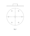
- FIG. 1 The outer shell surrounding the generator 1 - Magnets 2 - Compressed plastic insulators round the coils 3 - The core of the generator 4 - Outer shells of the sides 5 - Coils 6 - The internal holder plate of the generator 7 - Holder (Supporting) screws 8 - Outer shells of the sides 9 - The ball bearing of the outer shell 10 .
- This product can quickly replace the diesel and gasoline generators on the market, and by investing more, the power plants prototypes can be manufactured.
- This device can be used in agriculture, industry, home applications, the industry of electric cars, factories, and especially areas far from the electricity grid.
Landscapes
- Engineering & Computer Science (AREA)
- Power Engineering (AREA)
- Connection Of Motors, Electrical Generators, Mechanical Devices, And The Like (AREA)
Abstract
La présente invention concerne une machine constituée d'un moteur en CA, d'un générateur fait à la main et d'un cycle en roue libre mécanique connectés les uns aux autres, ce qui inclut également une carte électronique de commande de moteur en CA. Le générateur est constitué de deux parties, une fixe et une mobile. La partie fixe implique les noyaux et les bobines, tandis que la partie mobile du générateur contient la coque extérieure. Les composants de ce générateur incluent 48 aimants, des plastiques compacts, des bobines électromagnétiques, une coque extérieure, et deux arbres et roulements à billes. La coque en contact avec l'aimant mobile tourne sur le rotor fixe avec la bobine, laquelle conduit complètement l'opération d'induction. Une plaque de rétention rotative est située à l'intérieur de la bille de roulement à l'aide d'un arbre incorporé en son milieu, lequel maintient le générateur stable et fixe.
Priority Applications (1)
| Application Number | Priority Date | Filing Date | Title |
|---|---|---|---|
| PCT/IB2019/050091 WO2020144492A1 (fr) | 2019-01-07 | 2019-01-07 | Générateur à cycle combiné à rendement de 100 % |
Applications Claiming Priority (1)
| Application Number | Priority Date | Filing Date | Title |
|---|---|---|---|
| PCT/IB2019/050091 WO2020144492A1 (fr) | 2019-01-07 | 2019-01-07 | Générateur à cycle combiné à rendement de 100 % |
Publications (1)
| Publication Number | Publication Date |
|---|---|
| WO2020144492A1 true WO2020144492A1 (fr) | 2020-07-16 |
Family
ID=71521058
Family Applications (1)
| Application Number | Title | Priority Date | Filing Date |
|---|---|---|---|
| PCT/IB2019/050091 Ceased WO2020144492A1 (fr) | 2019-01-07 | 2019-01-07 | Générateur à cycle combiné à rendement de 100 % |
Country Status (1)
| Country | Link |
|---|---|
| WO (1) | WO2020144492A1 (fr) |
Cited By (1)
| Publication number | Priority date | Publication date | Assignee | Title |
|---|---|---|---|---|
| WO2025022171A1 (fr) * | 2023-12-04 | 2025-01-30 | Rezaei Sani Meysam | Générateur à cycle combiné ayant une efficacité maximale |
Citations (4)
| Publication number | Priority date | Publication date | Assignee | Title |
|---|---|---|---|---|
| US5962939A (en) * | 1997-01-22 | 1999-10-05 | Honda Giken Kogyo Kabushiki Kaisha | Outer-rotor type engine-operated generator |
| US20060250034A1 (en) * | 2002-09-25 | 2006-11-09 | Jun Umezu | Outer rotor type multipolar generator |
| DE202008000580U1 (de) * | 2008-01-15 | 2008-03-20 | Lin, Lily, Yuanshan | Kombinierter Generator mit einem eingebauten, magnetischen Wirbelstromwiderstand |
| US20090174271A1 (en) * | 2008-01-08 | 2009-07-09 | Lily Lin | Combined generator with built-in eddy-current magnetic resistance |
-
2019
- 2019-01-07 WO PCT/IB2019/050091 patent/WO2020144492A1/fr not_active Ceased
Patent Citations (4)
| Publication number | Priority date | Publication date | Assignee | Title |
|---|---|---|---|---|
| US5962939A (en) * | 1997-01-22 | 1999-10-05 | Honda Giken Kogyo Kabushiki Kaisha | Outer-rotor type engine-operated generator |
| US20060250034A1 (en) * | 2002-09-25 | 2006-11-09 | Jun Umezu | Outer rotor type multipolar generator |
| US20090174271A1 (en) * | 2008-01-08 | 2009-07-09 | Lily Lin | Combined generator with built-in eddy-current magnetic resistance |
| DE202008000580U1 (de) * | 2008-01-15 | 2008-03-20 | Lin, Lily, Yuanshan | Kombinierter Generator mit einem eingebauten, magnetischen Wirbelstromwiderstand |
Cited By (1)
| Publication number | Priority date | Publication date | Assignee | Title |
|---|---|---|---|---|
| WO2025022171A1 (fr) * | 2023-12-04 | 2025-01-30 | Rezaei Sani Meysam | Générateur à cycle combiné ayant une efficacité maximale |
Similar Documents
| Publication | Publication Date | Title |
|---|---|---|
| US20070007771A1 (en) | Energy recovery system | |
| US10458269B2 (en) | Controllable multi-spool gas turbine plant with independent generator speed control and hollow turbine-compressor separator | |
| US10626746B2 (en) | Controllable two-spool gas turbine arrangement | |
| ZA200602322B (en) | Energy recovery system | |
| WO2020144492A1 (fr) | Générateur à cycle combiné à rendement de 100 % | |
| US20130121844A1 (en) | Variable Speed High Efficiency Gas Compressor System | |
| WO2025022171A1 (fr) | Générateur à cycle combiné ayant une efficacité maximale | |
| WO2013155491A1 (fr) | Système de stockage d'énergie à gaz comprimé | |
| RU186778U1 (ru) | Ветрогенератор | |
| Istiawan et al. | Analysis of Steam Power Generators in Fulfilling Electricity Needs: A Case Study at PT Madubaru Yogyakarta, Indonesia | |
| JP2021527775A (ja) | 熱電分散型コジェネレーション用のコンパクトなランキンターボジェネレータ装置 | |
| US20210293181A1 (en) | A system and a method for power generation | |
| RU2323347C1 (ru) | Способ работы тепловой электрической станции | |
| Syahputra et al. | Performance Analysis of Synchronous Generator: A Case Study in Steam Power Plant at PT POMI Paiton Unit 7 Probolinggo, East Java, Indonesia | |
| Thirion et al. | Natural Gas for Power Generation | |
| CN202946245U (zh) | 十字型排列的离心式微小型燃气轮机 | |
| KR20070020365A (ko) | 에너지 회수 시스템 | |
| US20170298782A1 (en) | System and method for increasing the responsiveness of a duct fired, combined cycle, power generation plant | |
| Shumilin | Development of low-power high-speed turbogenerator | |
| RU120145U1 (ru) | Газотурбинная установка с накопителем энергии | |
| Kovalenko et al. | Multi-fuel Autonomous Electric Generating Unit with Stabilization System of the Output Voltage | |
| Kushary et al. | A Review of Wind Energy Conversion System | |
| Adi Widodo et al. | Design And Construction Of Wind Power For Street Lighting | |
| GB2498540A (en) | A gas turbine heat and electricity generating apparatus | |
| WO2014155392A2 (fr) | Procédé et dispositif de génération d'énergie électrique par distribution d'énergie électrique |
Legal Events
| Date | Code | Title | Description |
|---|---|---|---|
| 121 | Ep: the epo has been informed by wipo that ep was designated in this application |
Ref document number: 19909272 Country of ref document: EP Kind code of ref document: A1 |
|
| NENP | Non-entry into the national phase |
Ref country code: DE |
|
| 122 | Ep: pct application non-entry in european phase |
Ref document number: 19909272 Country of ref document: EP Kind code of ref document: A1 |