WO2020145023A1 - Appareil et programme d'analyse de caractéristiques optiques - Google Patents
Appareil et programme d'analyse de caractéristiques optiques Download PDFInfo
- Publication number
- WO2020145023A1 WO2020145023A1 PCT/JP2019/048744 JP2019048744W WO2020145023A1 WO 2020145023 A1 WO2020145023 A1 WO 2020145023A1 JP 2019048744 W JP2019048744 W JP 2019048744W WO 2020145023 A1 WO2020145023 A1 WO 2020145023A1
- Authority
- WO
- WIPO (PCT)
- Prior art keywords
- reflection component
- measured
- image data
- specular reflection
- optical characteristic
- Prior art date
- Legal status (The legal status is an assumption and is not a legal conclusion. Google has not performed a legal analysis and makes no representation as to the accuracy of the status listed.)
- Ceased
Links
Images






Classifications
-
- G—PHYSICS
- G01—MEASURING; TESTING
- G01N—INVESTIGATING OR ANALYSING MATERIALS BY DETERMINING THEIR CHEMICAL OR PHYSICAL PROPERTIES
- G01N21/00—Investigating or analysing materials by the use of optical means, i.e. using sub-millimetre waves, infrared, visible or ultraviolet light
- G01N21/84—Systems specially adapted for particular applications
- G01N21/8422—Investigating thin films, e.g. matrix isolation method
-
- G—PHYSICS
- G01—MEASURING; TESTING
- G01N—INVESTIGATING OR ANALYSING MATERIALS BY DETERMINING THEIR CHEMICAL OR PHYSICAL PROPERTIES
- G01N21/00—Investigating or analysing materials by the use of optical means, i.e. using sub-millimetre waves, infrared, visible or ultraviolet light
- G01N21/17—Systems in which incident light is modified in accordance with the properties of the material investigated
- G01N21/55—Specular reflectivity
-
- G—PHYSICS
- G01—MEASURING; TESTING
- G01N—INVESTIGATING OR ANALYSING MATERIALS BY DETERMINING THEIR CHEMICAL OR PHYSICAL PROPERTIES
- G01N21/00—Investigating or analysing materials by the use of optical means, i.e. using sub-millimetre waves, infrared, visible or ultraviolet light
- G01N21/17—Systems in which incident light is modified in accordance with the properties of the material investigated
- G01N21/55—Specular reflectivity
- G01N2021/557—Detecting specular reflective parts on sample
-
- G—PHYSICS
- G01—MEASURING; TESTING
- G01N—INVESTIGATING OR ANALYSING MATERIALS BY DETERMINING THEIR CHEMICAL OR PHYSICAL PROPERTIES
- G01N21/00—Investigating or analysing materials by the use of optical means, i.e. using sub-millimetre waves, infrared, visible or ultraviolet light
- G01N21/84—Systems specially adapted for particular applications
- G01N21/8422—Investigating thin films, e.g. matrix isolation method
- G01N2021/8427—Coatings
-
- G—PHYSICS
- G01—MEASURING; TESTING
- G01N—INVESTIGATING OR ANALYSING MATERIALS BY DETERMINING THEIR CHEMICAL OR PHYSICAL PROPERTIES
- G01N21/00—Investigating or analysing materials by the use of optical means, i.e. using sub-millimetre waves, infrared, visible or ultraviolet light
- G01N21/17—Systems in which incident light is modified in accordance with the properties of the material investigated
- G01N21/55—Specular reflectivity
- G01N21/57—Measuring gloss
Definitions
- the present invention relates to an optical characteristic analysis device and a program for analyzing the surface optical characteristics of an object to be measured having a bright material-containing layer containing a flake-shaped aluminum piece, a mica piece or a pigment, which is called a bright material, in a surface layer portion. ..
- the coatings containing the above-mentioned luster materials appear to have different colors depending on the observation angle, they are widely used in various industrial products such as automobiles that require designability as metallic coatings or pearl coatings. It is used.
- Patent Document 1 discloses that a measured object is illuminated from a specific direction or diffused illuminated from all directions, and reflected light is reflected.
- a method has been proposed in which a two-dimensional sensor receives light and the reflected image is analyzed to quantify the brilliance and particle sensation of an object to be measured, which is expressed by a brilliant material contained in the interior of an automobile paint.
- -Highly designed pigments may exhibit physical properties such as high brightness and high saturation only near specular reflection.
- the light distribution component of the luster material is concentrated in the horizontal direction of the coating film, and the reflected light reaches the vicinity of regular reflection, For these reasons, the inventors have found that it is good to measure the surface in the vicinity of specular reflection.
- the reflected light received by the two-dimensional sensor includes only the reflected light of the glittering material and the surface of the measured object only.
- the reflected light of will be included.
- the present invention has been made in view of such a technical background, and a substantially regular reflection direction when illumination light is irradiated from an illumination device to an object to be measured having a luster material-containing layer in a surface layer portion.
- the optical characteristics of the glitter material are analyzed from the image data obtained by receiving the reflected light of the glittering light by a two-dimensional photoelectric conversion element, the optical characteristics of the glitter material cannot be directly evaluated, or near specular reflection. It is an object of the present invention to provide an optical characteristic analysis device and a program capable of solving the problem that the angle change of the particle feeling of the glitter material cannot be quantified.
- Image data by receiving reflected light in a substantially regular reflection direction when the illumination light is irradiated from the illumination device to the object to be measured having a single illumination device and a surface layer portion containing a glittering material
- a two-dimensional photoelectric conversion element to convert to, the image data, a calculating means for calculating the specular reflection component of only the surface of the measured object, only the surface of the measured object calculated by the calculating means
- An optical characteristic analyzing apparatus comprising: an extracting unit that extracts a reflection component of the glitter material by subtracting a regular reflection component from the entire image data.
- the calculating means calculates the specular reflection component of only the surface of the object to be measured by fitting the image data with a predetermined model function matching the illuminance distribution of the illumination device to the object to be measured.
- the optical characteristic analyzing device according to the above 1 or 2.
- the calculation means performs an analysis at a place on the image data that can be regarded as having an equivalent illuminance in an illuminance distribution of the illumination device to the object to be measured, and is common to places where it can be regarded as having an equivalent illuminance.
- the optical characteristic analyzing apparatus according to 1 or 2 above, wherein the specular reflection component of only the surface of the object to be measured is calculated by obtaining the specular reflection component of.
- the calculation means is the same as the first processing for fitting with a predetermined model function that matches the illuminance distribution of the illumination device to the DUT, and the illuminance distribution of the illumination device to the DUT.
- the optical device obtains the luminance of a place on the image data that can be regarded as having the same illuminance, and sets the minimum value of the luminance as a specular reflection component common to the place.
- Characteristic analysis device (7)
- the calculation means includes a frequency component of a predetermined threshold value or less among frequency domain data obtained by performing a Fourier transform on luminance information of a place on the image data that can be regarded as having the same illuminance. 6.
- the optical characteristic analyzing apparatus according to item 4 or 5, wherein the data obtained by subjecting the extracted data to the inverse Fourier transform of the extracted data is a specular reflection component common to the location.
- the calculating means determines the value of the image data.
- the optical characteristic analyzing apparatus according to any one of items 4 to 7, which is not used for calculating a specular reflection component of only the surface of the object to be measured.
- the calculating means determines the value of the image data of the object to be measured. 8.
- the optical characteristic analyzer according to any one of items 4 to 7 above, which is not used for calculating a specular reflection component of only the surface.
- the calculating means determines the value of the image data. 10.
- the optical characteristic analyzer according to any one of items 4 to 9 above, which is not used for calculating a specular reflection component of only the surface of the object to be measured.
- the calculation means calculates the value of the image data from the surface of the object to be measured. 10.
- the optical characteristic analyzing apparatus according to any one of items 4 to 9 above, which is not used for calculation of the specular reflection component only.
- the optical characteristic analyzer according to the above item 3 or 5, wherein the predetermined model function adapted to the illuminance distribution by the illumination device is a polynomial function of 0th order or more.
- the optical characteristic analyzing device according to the above item 3 or 5, wherein the predetermined model function adapted to the illuminance distribution by the illumination device is a periodic function.
- the optical characteristic analysis device according to the above 3 or 5, wherein the predetermined model function adapted to the illuminance distribution by the illumination device is a Gaussian function.
- the image data obtained by receiving the reflected light by the photoelectric conversion element when the illumination light is irradiated from the single illumination device with respect to the DUT having the bright material-containing layer on the surface layer portion Based on the calculation step of calculating the specular reflection component of only the surface of the measured object, the specular reflection component of only the surface of the measured object calculated by the calculation step, subtracted from the image data, the brightness A program for causing a computer to execute an extraction step of extracting a reflection component of a material.
- the specular reflection component of only the surface of the object to be measured is calculated by fitting the image data with a predetermined model function that matches the illuminance distribution of the illumination device to the object to be measured. 17.
- the program according to item 16 which causes the computer to execute a process to be performed.
- an analysis is performed at a place on the image data that can be regarded as having an equivalent illuminance in an illuminance distribution by the illumination device to the object to be measured, and is common to places where it can be regarded as having an equivalent illuminance.
- the first processing for fitting a measured object to the object to be measured by a predetermined model function in accordance with the illuminance distribution of the lighting apparatus is the same as the illuminance distribution to the object to be measured by the illumination apparatus.
- a second process for analyzing the value of the image data for each place that can be regarded as having an illuminance of 2 and obtaining a specular reflection component specific to each place for the entire image data 17.
- the program according to item 16 which causes the computer to execute a process of calculating a specular reflection component of only the surface of the measurement object.
- the reflected light when the illumination light is irradiated from the single illumination device to the object to be measured having the glittering material-containing layer in the surface layer portion is subjected to two-dimensional photoelectric conversion.
- the specular reflection component only on the surface of the object to be measured is calculated based on the image data obtained by the light received by the element.
- the regular reflection component of the glitter material is extracted.
- the specular reflection component of only the surface of the measured object can be removed, it is possible to directly and accurately determine the optical characteristics of the luster material in the vicinity of the specular reflection of the measured object. It is possible to solve the problems that the direct evaluation cannot be performed and the angle change of the graininess of the glittering material in the vicinity of regular reflection cannot be quantified. Further, both the specular reflection component of only the glitter material and the specular reflection component of only the surface of the measured object can be obtained, so that the ratio of the glitter material in the glitter feeling of the measured object can be quantified. Furthermore, since only the reflection component of the glitter material can be extracted, it is possible to compare data acquired at various light-receiving angles including the vicinity of the regular reflection angle.
- the lighting device can display a specific lighting pattern
- a display device such as a liquid crystal display that can display the specific lighting pattern can be used as the lighting device.
- the specular reflection component only on the surface of the object to be measured is surely obtained by fitting the image data by a predetermined model function that matches the illuminance distribution of the illumination device to the object to be measured. Can be calculated.
- the image data is analyzed for each place that can be regarded as having the same illuminance in the illuminance distribution of the illumination device for the object to be measured, and the specular reflection component unique to each place is obtained.
- the specular reflection component of only the surface of the object to be measured can be reliably calculated.
- the first process for fitting with a predetermined model function that matches the illuminance distribution of the illumination device to the DUT is equivalent to the illuminance distribution of the illumination device to the DUT.
- the surface of the object to be measured is analyzed by analyzing the value of the image data for each place that can be regarded as having the illuminance, and performing the second process for obtaining the specular reflection component peculiar to each place on the entire image data. It is possible to accurately calculate only the regular reflection component.
- the luminance of the image data in a place that can be regarded as having the same illuminance is analyzed, and the minimum value of the luminance is used as the peculiar specular reflection component in the place. It is possible to reliably calculate the specular reflection component of only the surface.
- Data that is obtained by extracting the data that has a component and performing inverse Fourier transform on the extracted data is used as the regular specular reflection component at that location, so the specular reflection component of only the surface of the DUT can be reliably calculated. can do.
- image data of a small value that does not fall within the predetermined dispersion is regarded as a noise component and is not used for calculating the specular reflection component of only the surface of the object to be measured.
- the specular reflection component of only the surface of the object to be measured can be calculated more accurately.
- the image data having a value smaller than the predetermined threshold value is regarded as a noise component and is not used for calculating the specular reflection component of only the surface of the object to be measured.
- the specular reflection component of only the surface of the object can be calculated more accurately.
- the image data having a large value that does not fall within the predetermined dispersion is regarded as something other than the specular reflection component only on the surface of the measured object including the reflection by the glittering material, and Since it is not used for calculating the specular reflection component of only the surface of the measured object, the specular reflection component of only the surface of the measured object can be calculated with higher accuracy.
- the image data having a value exceeding the predetermined threshold value is regarded as something other than the specular reflection component of only the surface of the object to be measured including reflection by the glittering material, and the object to be measured is considered. Since it is not used for calculating the specular reflection component of only the surface, the specular reflection component of only the surface of the object to be measured can be calculated more accurately.
- the measured data is fitted by fitting the image data with a polynomial function of 0 or higher order, a periodic function, an exponential function, or a Gaussian function, which is adjusted to the illuminance distribution by the lighting device. It is possible to accurately calculate the specular reflection component of only the surface of the object.
- the reflected light when the illumination light is irradiated from the single illumination device to the object to be measured having the glittering material-containing layer in the surface layer portion is subjected to two-dimensional photoelectric conversion.
- calculate the specular reflection component of only the surface of the DUT by subtracting the specular reflection component of the calculated surface of the DUT from the image data.
- the computer can be caused to execute the process of extracting the specular reflection component of the glitter material contained in the surface layer of the object to be measured.
- the image data is fitted by a predetermined model function that matches the illuminance distribution of the illumination device to the object to be measured, so that only the surface of the object to be measured is corrected.
- the computer can be caused to execute the process of calculating the reflection component.
- the image data is analyzed for each place that can be regarded as having the same illuminance in the illuminance distribution by the illumination device to the object to be measured, and the unique positive value for each place is analyzed.
- the first process of fitting with a predetermined model function matching the illuminance distribution of the illumination device to the object to be measured and the illumination device to the object to be measured are performed.
- a second process of analyzing the value of the image data for each place that can be regarded as having the same illuminance in the illuminance distribution and obtaining the specular reflection component peculiar for each place the entire image data is processed.
- the computer can be caused to execute the process of calculating the regular reflection component of only the surface of the measurement object.
- FIG. 3A is the same two-dimensional image as in FIG. 3C
- FIG. 3B is a graph in which the vertical axis represents the luminance and the horizontal axis represents the distance r from the center.
- 3A is the same two-dimensional image as in FIG. 3C, FIG.
- FIG. 3B is a graph in which the vertical axis represents the luminance of a pixel on a concentric circle, and the horizontal axis represents the central angle ⁇ .
- FIG. 5 is a graph showing the reflection component of the glitter material in FIG.
- (A) is a graph in which the vertical axis represents the luminance of pixels on a certain concentric circle and the horizontal axis represents the central angle ⁇
- (B) is a graph in which small luminance is excluded
- (C) represents the concentric circle. It is a graph which shows the reflection component of a glitter material.
- (A) is a graph in which the vertical axis represents the luminance of a pixel on a certain concentric circle, and the horizontal axis represents the central angle ⁇ .
- (B) is a graph in which large luminance is excluded. It is a graph which shows the reflection component of a glitter material.
- (A) is a plane image of an illumination device displaying another illumination pattern
- (B) is a two-dimensional image obtained by a photoelectric conversion element.
- 8A is the same two-dimensional image as in FIG. 8B
- FIG. 8B is the two-dimensional image in FIG. 8A, where the vertical axis represents the luminance and the horizontal axis represents the position X from the center with the highest luminance.
- Is a graph of. 8A is the same two-dimensional image as FIG. 8B, FIG.
- FIG. 8B is a graph in which the vertical axis represents the luminance of pixels on a certain column and the horizontal position represents the vertical position Y; Is a graph showing the reflection component of the glittering material in that row.
- (A) is a graph in which the vertical axis represents the luminance of pixels on a certain column and the horizontal position represents the vertical position Y.
- (B) is a graph in which small luminance is excluded. It is a graph which shows the reflection component of the bright material in a row.
- (A) is a graph in which the vertical axis represents the brightness of pixels on a certain column and the horizontal position represents the vertical position Y.
- (B) is a graph in which large brightness is excluded. It is a graph which shows the reflection component of the bright material in a row.
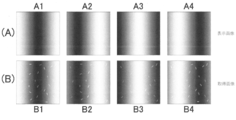
- FIG. 13A is a plane image of the illumination device displaying another illumination pattern
- FIG. 13B is the two-dimensional image acquired by the photoelectric conversion element during illumination by each front pattern.
- 13A is the same two-dimensional image as B1 in FIG. 13B
- FIG. 13B is the two-dimensional image in FIG. 13A.
- the vertical axis represents the brightness and the horizontal axis represents the distance X from the center of the highest brightness. It is a graph when it is.
- 13A is the same two-dimensional image as B1 in FIG. 13B
- FIG. 13B is a graph in which the vertical axis represents the luminance of pixels on a certain column and the horizontal position represents the vertical position Y.
- C) is a graph showing the reflection component of the glittering material in that row.
- FIG. 1 is a block diagram showing the configuration of an optical characteristic analyzing apparatus according to an embodiment of the present invention.
- the optical characteristic analyzing apparatus shown in FIG. 1 includes a single illuminating device 1, an objective lens 2, a two-dimensional photoelectric conversion element 3 including a CCD sensor, a computing unit 4, a liquid crystal display device, and the like.
- the measurement result display unit 5 is provided.
- the illuminating device 1 is configured by a display device that can display a specific illumination pattern in this embodiment, and illuminates the measurement site 100a of the DUT 100 with the illumination light L1 from the displayed illumination pattern.
- a point light source or the like may be used as the lighting device 1.
- the DUT 100 has a translucent luster material-containing layer 101 containing a luster material 110 in the surface layer portion, and the luster material-containing layer 101 further has a surface.
- a translucent clear layer 102 is formed.
- the glitter material-containing layer 101 and the clear layer 102 are formed, for example, by coating the surface of the sample 100 with a transparent resin containing the glitter material 110, and then coating the clear layer 102.
- the photoelectric conversion element 3 includes a large number of pixels arranged two-dimensionally, receives the reflected light L2 from the DUT 100 through the objective lens 2 for each pixel, and forms two-dimensional image data. Convert and output.
- the lighting device 1 and the photoelectric conversion element 3 are arranged in such a positional relationship that the photoelectric conversion element 3 can receive the reflected light in the substantially regular reflection direction from the measured portion 100a.
- the term “generally specular reflection direction” is intended to allow not only reflected light in the specular reflection direction but also reflected light slightly deviated from the specular reflection direction.
- the reason for this arrangement relationship is that when the bright material-containing layer 101 is formed of a coating film containing a bright material, the orientation distribution of the bright material in the coating film is generally in the horizontal direction of the coating surface. This is because the distribution has a peak in the (0 degree direction), and such information in the vicinity of regular reflection of the glitter material can be accurately captured.
- the surface of the measured portion 100a of the sample 100 and the photoelectric conversion element 3 have a conjugate relationship.
- the image data which is an electric signal output from the photoelectric conversion element 3, is converted into a digital signal through an IV conversion circuit and an AD conversion circuit (not shown) as necessary, and sent to the arithmetic unit 4.
- the image data sent to the calculation unit 4 includes the specular reflection component from only the surface of the DUT 100 in addition to the reflected light component of the glitter material 110. Therefore, the calculation unit 4 uses the CPU or the like to calculate the specular reflection component of only the surface of the DUT 100, and subtracts the calculated specular reflection component of only the surface of the DUT 100 from the image data to obtain the DUT.
- a process of extracting the reflection component of the glitter material 110 included in the glitter material-containing layer 101 of the object 100 is executed. These processes will be described later.
- the arithmetic unit 4 may be a dedicated device or may be configured by a personal computer.
- the image data output from the photoelectric conversion element 3 and processed into a digital signal may be sent to the arithmetic unit 4 via a network. In this case, even if the calculation unit 4 is present in a place apart from the measurement location, the process of calculating the specular reflection component of only the surface of the DUT 100, the reflection component of the glitter material 110 included in the glitter material-containing layer 101. Can be extracted.
- the photoelectric conversion element 3 In order for the photoelectric conversion element 3 to detect a phenomenon visually observed, the photoelectric conversion element 3 needs a spatial resolution equivalent to that of a human eye. According to one study, the minimum width that the human eye can distinguish is about 0.6 minutes. If the distance from the pupil to the observed object is 20 to 30 cm, the distance between two distinguishable points is calculated to be 30 to 50 ⁇ m.
- the particle diameter of the glitter material contained inside the coating film is 10 to 20 ⁇ m for the small one and about 100 ⁇ m for the large one. It is more desirable that the photoelectric conversion element 3 be capable of spatially distinguishing each glitter material.
- the spatial resolution of the photoelectric conversion element 3 is about 10 to 100 ⁇ m.
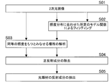
- FIG. 2 is a flowchart showing these processing procedures.
- a process of calculating the regular reflection component of only the surface of the DUT 100 is executed in step S02 and/or step S03.
- step S04 the calculated specular reflection component of only the surface of the DUT 100 is subtracted from the image data and removed, whereby the reflection component of the glitter material 110 is extracted in step S05.
- step S02 Whether the calculation process of the specular reflection component only on the surface of the DUT 100 is performed by fitting the image data by a predetermined model function that matches the illuminance distribution of the illumination device 1 on the DUT 100 (step S02). This is performed by analyzing the image data for each place where the illuminance distribution of the illumination device 1 on the DUT 100 can be regarded as having an equivalent illuminance (step S03), or a combination of both.
- step S03 equivalent illuminance
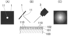
- Embodiment 1 It is assumed that the object to be measured 100 is illuminated by displaying on the illumination device 1 a point that is sufficiently smaller than the distance from the object to be measured 100. The same applies when a light source that is sufficiently smaller than the distance from the object to be measured 100 is used as the illumination device 1.
- a planar image of the illumination device 1 also simply referred to as a display image
- B a schematic diagram of a measurement system
- C a two-dimensional image acquired by the photoelectric conversion element 3 (simply (Also referred to as an acquired image).
- the white spot 11 at the center is the illuminated portion, and in this display image and the acquired image shown in FIG. 3C, the white portion has high brightness and the black portion has low brightness. Represents. Further, the white fine line segment in the acquired image of FIG. 7C represents the reflected light from the glitter material 110.
- the photoelectric conversion element 3 acquires a small white spot 11 on the illumination device 1 as a blurred image.
- the calculation unit 4 obtains the brightness for each pixel in the acquired two-dimensional image data. Then, using the obtained luminance data, the following calculation process of the specular reflection component only on the surface of the DUT 100 is executed.
- Step S2 of FIG. 2 This process is the process of step S2 of FIG. 2, that is, by fitting the image data with a predetermined model function that matches the illuminance distribution of the illumination device 1 on the object to be measured 100, only the surface of the object to be measured 100 is corrected.
- the reflection component is calculated.
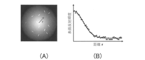
- the brightness is highest at the center of the blurred white point and decreases as the distance from the center increases. ..
- the density of the glittering material 110 is sufficiently small, the luminance distribution from the central portion having the highest luminance in the acquired image in the radial direction is represented by a two-dimensional Gaussian function.
- FIG. 4(A) is the same acquired image as FIG. 3(C)
- FIG. 4(B) is a graph when the vertical axis is the luminance and the horizontal axis is the distance r from the center.
- Many black dots in the graph of FIG. 4B are measured values of the brightness of each pixel in the radius r direction measured in the acquired image.
- the specular reflection component of only the surface of the measured object 100 thus obtained is subtracted from the measured value of the luminance data to extract the reflected component of the bright material 110 contained in the bright material-containing layer 101 of the measured object 100. ..
- step S3 of FIG. 2 This processing is performed in step S3 of FIG. 2, that is, by analyzing the image data for each place where it can be considered that the illuminance distribution of the illumination device 1 on the DUT 100 has the same illuminance.
- the brightness of the surface reflection is equal on the concentric circle from the place showing the maximum brightness.
- the reflection component of the glitter material 110 is added.
- the place on the concentric circle where no glittering material is present should show the minimum value of the luminance
- the specular reflection of only the surface of the DUT 100 on the concentric circle is obtained. The components can be calculated reliably.
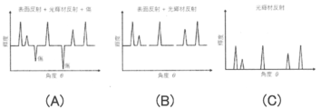
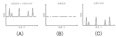
- FIG. 5(A) is the same acquired image as FIG. 3(C), and FIG. 5(B) is a graph with the vertical axis representing the luminance of pixels on a certain concentric circle and the horizontal axis representing the central angle ⁇ . is there.
- the minimum value of the luminance in the graph of FIG. 5B is the specular reflection component only on the surface of the DUT 100 on the concentric circle. Then, when this regular reflection component is subtracted from each luminance data of FIG. 5B, a graph as shown in FIG. 5C is obtained, and the reflection component of the glittering material 110 on the concentric circle is displayed.
- the calculation processing on the concentric circles is performed for each concentric circle while changing the distance r from the center, and the specular reflection component of only the surface of the DUT 100 on each concentric circle is calculated, and each calculated value is calculated.
- the reflection component of the glitter material can be obtained.
- the minimum value of the brightness on the concentric circle is set as the specular reflection component of only the surface of the DUT 100.
- the minimum value of the brightness on the concentric circle is only the original surface of the object to be measured 100. Is smaller than the regular reflection component of, and the calculation accuracy of the regular reflection component is reduced.
- the small brightness caused by scratches, dirt, unevenness, etc. is excluded and is not used for calculating the specular reflection component of only the surface of the DUT 100. Is desirable. Thereby, the specular reflection component of only the surface of the DUT 100 can be accurately calculated.
- a method of excluding a small luminance that does not fall within a preset variance (standard deviation) from the average value, or excluding a luminance smaller than a preset threshold value can be mentioned. ..
- the method of excluding small luminances that do not fall within the preset variance (standard deviation) from the average value is effective when the location of scratches, stains, and irregularities on the concentric circle is sufficiently small.
- the specular reflection component of only the surface of the DUT 100 on the concentric circle is calculated, and the specular reflection component on each calculated concentric circle is calculated. Is subtracted from each of the brightness data on the concentric circles, the reflection component of the glitter material 110 can be extracted.
- FIG. 6A is a graph in which the vertical axis represents the luminance of a pixel on a certain concentric circle and the horizontal axis represents the central angle ⁇ .
- the luminance is small in a portion where a scratch or the like exists. If these small luminances are excluded, the graph of FIG.
- the minimum value of the luminance in the graph of FIG. 6B is the specular reflection component of only the surface of the DUT 100 on the concentric circle.
- a graph as shown in FIG. 6C is obtained, which is the reflection component of the glitter material 110 in the concentric circle.
- the specular reflection component of only the surface of the DUT 100 is calculated in a state where the reflection component of the glitter material 110 is excluded.
- a large brightness that does not fall within a preset variance (standard deviation) from the average value is excluded, or a brightness that is larger than a preset threshold value is excluded. This is because these luminances are considered to be reflection components due to the glitter material 110.
- the method of excluding a large luminance that does not fall within the preset dispersion (standard deviation) from the average value is particularly effective when the ratio of the glittering material 110 on the concentric circles is sufficiently small.
- the reflection component of the glitter material 110 can be extracted.
- FIG. 7A is a graph in which the vertical axis represents the brightness of pixels on a certain concentric circle and the horizontal axis represents the central angle ⁇ .
- the graph of FIG. 7B is obtained when large brightness is excluded. From each luminance data in the graph of FIG. 7B, the specular reflection component of only the surface of the DUT 100 on the same circle is obtained, and the obtained specular reflection component is subtracted from each luminance data of FIG. 7A. Then, a graph as shown in FIG. 7C is obtained, which is the reflection component of the glitter material 110 in the concentric circle.
- the surface of the DUT 100 is obtained by combining the processing of the above-described embodiment 1-2 (processing of step S3 of FIG. 2) and the processing of embodiment 1-1 (processing of step S2 of FIG. 2). Only the specular reflection component is calculated.
- the minimum value of the brightness on the concentric circle is set as the specular reflection component only on the surface of the DUT 100, but a constant noise is added to each of the obtained values.
- a constant noise is added to each of the obtained values.
- the specular reflection component of only the surface of the DUT 100 can be calculated with high accuracy.
- the illumination device 1 illuminates the DUT 100 by displaying a point that is sufficiently smaller than the distance from the DUT 100.
- the same optical system as that of the first embodiment is used to illuminate the DUT 100 by displaying a line that is sufficiently thin in comparison with the distance from the DUT 100 on the illumination device 1. The same applies when a linear light source that is sufficiently thinner than the distance from the object to be measured 100 is used as the illumination device 1.
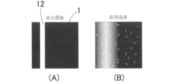
- FIG. 8A shows a display image of the lighting device 1
- FIG. 8B shows an image obtained by the photoelectric conversion element 3.
- the vertically long white line 12 is an illuminated portion
- white portions represent high luminance and black portions represent low luminance.
- the white fine line segment in the acquired image of FIG. 6B represents the reflected light from the glitter material 110.
- the photoelectric conversion element 3 acquires an illuminated portion on the illumination device 1 as a blurred image.
- the calculation unit 4 obtains the brightness for each pixel in the acquired two-dimensional image data. Then, using the obtained luminance data, the following calculation process of the specular reflection component only on the surface of the DUT 100 is executed.
- step S2 of FIG. 2 that is, by fitting the image data by a predetermined model function that matches the illuminance distribution of the illumination device 1 on the DUT 100, The specular reflection component of only the surface of the DUT 100 is calculated.
- the central part in the width direction (horizontal direction) of the blurred thin line has the highest brightness, and the central part has the highest brightness.
- the brightness decreases with increasing distance from the width direction.
- the vertical direction is a row, it can be considered that the luminance of the specularly reflected light from the surface of the DUT 100 is the same on the same row. Therefore, when the density of the glittering material 110 is sufficiently small, the brightness distribution of the acquired image has a Gaussian distribution in the horizontal direction and does not depend on the vertical coordinate, that is, the horizontal axis coordinate (column position) is used as a variable. It is shown by the Gaussian function.
- FIG. 9A shows the same acquired image as FIG. 8B.
- the vertical axis represents the luminance
- the horizontal axis represents the horizontal position (row position) X from the central portion having the highest brightness. It is a graph when taking. Many black dots in the graph of FIG. 9B are measured values of the brightness of each pixel in the X direction measured in the acquired image.
- the curve becomes as shown in FIG. 9B, and this curve is a positive curve of only the surface of the DUT 100. It is calculated as a reflection component.
- the specular reflection component of only the surface of the measured object 100 thus obtained is subtracted from the measured value of the luminance data to extract the reflected component of the bright material 110 contained in the bright material-containing layer 101 of the measured object 100. ..
- the brightness on the same column can be regarded as being equal.
- the reflection component of the glitter material 110 is added.
- the specular reflection component of only the surface of the DUT 100 in that row is obtained. Can be reliably calculated.
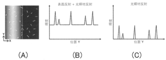
- FIG. 10A is the same acquired image as FIG. 8B, and assuming that the horizontal position is X and the vertical (column) position is Y, FIG. 10B shows the pixel on a certain column.
- 6 is a graph in which luminance is plotted on the vertical axis and vertical position Y is plotted on the horizontal axis.
- the calculation process on the same row is performed for each row by changing the position X in the horizontal direction, and the specular reflection component of only the surface of the DUT 100 on each row is calculated, and the calculated respective values are calculated. By subtracting the luminance data on each row, the reflection component of the glitter material 110 can be obtained.
- Embodiment 2-3 In this example, as in the case of Embodiment 1-3, when there are scratches, stains, irregularities, etc. on the surface of the object to be measured 100, the influence thereof is eliminated and only the surface of the object to be measured 100 is corrected. The calculation accuracy of the reflection component is improved.
- the small luminance due to scratches, stains, unevenness, etc. is excluded and is not used for calculating the specular reflection component of only the surface of the DUT 100. Is desirable. Thereby, the specular reflection component of only the surface of the DUT 100 can be accurately calculated.
- a method of excluding a small luminance that does not fall within a preset variance (standard deviation) from the average value, or excluding a luminance smaller than a preset threshold value can be mentioned. ..
- the method of excluding small luminances that do not fall within the preset dispersion (standard deviation) from the average value is effective when the location of scratches, stains, and irregularities on the same row is sufficiently small.
- the specular reflection component of only the surface of the DUT 100 on the same row is calculated, and the calculated specular reflection component on each same row is calculated. Is subtracted from each of the luminance data on the same column, the reflection component of the glitter material 110 can be extracted.
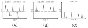
- FIG. 11A is a graph in which the vertical axis represents the luminance of a pixel on a certain column and the horizontal axis represents the position Y in the vertical axis direction.
- the luminance decreases when a scratch or the like exists. There is.
- the graph of FIG. 11B is obtained, and when the minimum value of the luminance in the graph of FIG. 11B is subtracted from each luminance data, the graph of FIG. And becomes a reflection component of the glitter material 110 at.
- Embodiment 2-4 In this example, as in the case of Embodiment 1-4, the specular reflection component of only the surface of the DUT 100 is calculated in a state where the reflection component of the glitter material 110 is excluded.
- the specular reflection component of only the surface of the DUT 100 on the same row is obtained.
- the inverse Fourier transform is performed after the frequency after the Fourier transform is less than or equal to the threshold value.
- FIG. 12A is a graph in which the vertical axis represents the luminance of pixels on a certain column and the horizontal position represents the vertical position Y.
- the graph in FIG. 12B is obtained. ..
- the specular reflection component of only the surface of the DUT 100 on the same row is obtained, and the obtained specular reflection component is subtracted from each luminance data of FIG. 12A.
- the graph is as shown in FIG. 12(C), which is the reflection component of the glittering material 110 in that column.
- FIG. 12(C) is the reflection component of the glittering material 110 in that column.
- the minimum value of the luminance on the same row is used as the specular reflection component of only the surface of the DUT 100, but a constant noise is added to each of the obtained values.
- a constant noise is added to each of the obtained values.
- the fitting process by the model function described in the embodiment 2-1 is performed. Specifically, the brightness data in the horizontal direction from the central part where the brightness is highest in the acquired image is used as the variable of the coordinates (column position) on the horizontal axis.
- the Gaussian function of 1) By combining the processing of fitting with the Gaussian function of 1), these noises can be removed and the regular reflection component of only the surface of the DUT 100 can be calculated with high accuracy.
- the specular reflection component of only the surface of the DUT 100 thus calculated is subtracted from the entire image data to extract the reflection component of the glitter material 110.
- the calculation process of the specular reflection component of only the surface of the DUT 100 will be described when the illumination device 1 that displays small dots is used in the first embodiment and the illumination device 1 that displays thin lines is used in the second embodiment. did.
- the illumination device 1 displaying an illumination pattern in which the brightness changes in one direction may be used.
- the illumination pattern in which the brightness changes in one direction a pattern in which the brightness changes periodically such as a sine wave or a cosine wave in the horizontal axis direction can be mentioned.
- the acquired images captured by the photoelectric conversion element 3 when the DUT 100 is illuminated with the illumination light of each of the display images A1 to A4 are shown in B1 to B4 of FIG. 13(B).
- the vertically long white lines are the illuminated portions, and in these display images A1 to A4 and the acquired images B1 to B4 of FIG. Black spots represent places with low brightness.
- White fine line segments in the acquired images B1 to B4 represent reflected light from the glitter material 110.
- the calculation unit 4 obtains the brightness for each pixel in the acquired two-dimensional image data. Then, using the obtained luminance data, the following calculation process of the specular reflection component only on the surface of the DUT 100 is executed.
- step S2 of FIG. 2 similarly to the embodiment 2-1, by performing the process of step S2 of FIG. 2, that is, by fitting the image data by a predetermined model function that matches the illuminance distribution of the illumination device 1 on the DUT 100, The specular reflection component of only the surface of the DUT 100 is calculated.
- the luminance distribution changes in the horizontal axis direction with a cosine wave
- the luminance of the specular reflection light from the surface of the DUT 100 is the same on the same row without depending on the coordinate in the vertical axis direction. Therefore, when the density of the glitter material 110 is sufficiently small, the brightness distribution of the acquired image is represented by a cosine function having a cosine wave in the horizontal axis direction and independent of the coordinate in the vertical axis direction.
- FIG. 14(A) is the same acquired image as B1 in FIG. 13(B), and FIG. 14(B) shows the position in the horizontal direction (the position of the row) from the central part where the vertical axis represents the brightness and the horizontal axis represents the highest brightness.
- FIG. 14(B) shows the position in the horizontal direction (the position of the row) from the central part where the vertical axis represents the brightness and the horizontal axis represents the highest brightness.
- a curve shown in FIG. 14B is obtained, and this curve is a positive curve of only the surface of the DUT 100. It is calculated as a reflection component.
- the specular reflection component of only the surface of the measured object 100 thus obtained is subtracted from the measured value of the luminance data to extract the reflected component of the bright material 110 contained in the bright material-containing layer 101 of the measured object 100. ..
- the reflection component of the glitter material 110 contained in the glitter material-containing layer 101 of the DUT 100 in the entire acquired image can be reliably extracted.
- the luminance on the same column can be regarded as being equal.
- the reflection component of the glitter material 110 is added.
- the specular reflection component of only the surface of the DUT 100 in that row is obtained. Can be reliably calculated.
- FIG. 15A is the acquired image B1 of FIG. 13B, and assuming that the horizontal position is X and the vertical (column) position is Y, FIG. 6 is a graph in which luminance is plotted on the vertical axis and vertical position Y is plotted on the horizontal axis.
- FIG. 15C When the minimum value of the luminance in the graph of FIG. 15B is subtracted from each luminance data, the graph is as shown in FIG. 15C, and the reflection component of the glittering material 110 in that column is displayed.
- the calculation process on the same row is performed for each row by changing the position X in the horizontal direction, and the specular reflection component of only the surface of the DUT 100 on each row is calculated, and the calculated respective values are calculated. By subtracting each of the brightness data on each row, the reflection component of the glitter material can be obtained.
- Embodiment 3-3 when there are scratches, stains, irregularities, etc. on the surface of the DUT 100, the influence thereof is excluded and the specular reflection component of only the surface of the DUT 100 is calculated. In order to improve the accuracy, the same processing as in the embodiment 2-3 may be executed.
- the same processing as that of the embodiment 2-4 is executed in order to calculate the regular reflection component of only the surface of the DUT 100 in a state where the reflection component due to the glitter material 110 is excluded. May be.
- the specular reflection component of only the surface of the DUT 100 can be calculated with higher accuracy. ..
- the specular reflection component of only the surface of the DUT 100 can be removed, the optical characteristics of the glitter material 110 near the specular reflection of the DUT 100. Can be obtained directly and accurately. Therefore, it is possible to solve the problems that the optical characteristics of the glitter material cannot be directly evaluated, and the angular change of the graininess of the glitter material 110 in the vicinity of regular reflection cannot be quantified. Further, both the specular reflection component of only the glitter material 100 and the specular reflection component of only the surface of the DUT 100 can be obtained, so that the ratio of the glitter material 110 in the glitter feeling of the DUT 100 can be quantified. Furthermore, since only the reflection component of the glitter material 110 can be extracted, it is possible to compare data acquired at various light reception angles including the vicinity of the regular reflection angle.
- the method for evaluating the optical characteristics of the glitter material 110 after removing the specular reflection component only from the surface of the DUT 100 is not limited, and various evaluation methods may be used.
- the present invention is not limited to the above embodiment.
- a Gaussian function or a periodic function such as a cosine wave or a sine wave is used as the model function, but another model is used according to the illuminance distribution according to the illumination pattern of the illumination device 1.
- a function for example, a polynomial function of 0th order or higher, an exponential function, or the like may be used.
- the present invention can be used for, for example, analyzing surface optical characteristics of an object to be measured having a bright material-containing layer containing a flaky aluminum piece, a mica piece, or a pigment, which is called a bright material, in a surface layer portion.
- Measurement result display part 100 Measurement object 100a Measured part 101 Bright material containing layer 102 Clear layer 110 Bright material
Landscapes
- Physics & Mathematics (AREA)
- Health & Medical Sciences (AREA)
- Life Sciences & Earth Sciences (AREA)
- Chemical & Material Sciences (AREA)
- Analytical Chemistry (AREA)
- Biochemistry (AREA)
- General Health & Medical Sciences (AREA)
- General Physics & Mathematics (AREA)
- Immunology (AREA)
- Pathology (AREA)
- Mathematical Physics (AREA)
- Investigating Or Analysing Materials By Optical Means (AREA)
Abstract
La présente invention concerne un appareil d'analyse de caractéristiques optiques qui est pourvu : d'un seul dispositif d'éclairage (100) ; d'un élément de conversion photoélectrique bidimensionnel (3) qui reçoit la lumière réfléchie, dans une direction de réflexion sensiblement régulière, obtenue lorsque de la lumière d'éclairage est appliquée depuis le dispositif d'éclairage vers un objet à mesurer (100) ayant une couche contenant un matériau brillant (101) sur une partie de couche de surface, et qui convertit la lumière réfléchie en données d'image ; un moyen de calcul (4) pour calculer une composante de réflexion régulière de seulement la surface de l'objet à mesurer à partir des données d'image ; et un moyen d'extraction (4) pour extraire une composante de réflexion d'un matériau brillant par soustraction de la composante de réflexion régulière, de seulement la surface de l'objet à mesurer, qui est calculée par le moyen de calcul, à partir de la totalité des données d'image.
Priority Applications (2)
| Application Number | Priority Date | Filing Date | Title |
|---|---|---|---|
| EP19908193.6A EP3889582B1 (fr) | 2019-01-10 | 2019-12-12 | Appareil et programme d'analyse de caractéristiques optiques |
| JP2020565649A JP7380596B2 (ja) | 2019-01-10 | 2019-12-12 | 光学特性解析装置及びプログラム |
Applications Claiming Priority (2)
| Application Number | Priority Date | Filing Date | Title |
|---|---|---|---|
| JP2019002534 | 2019-01-10 | ||
| JP2019-002534 | 2019-01-10 |
Publications (1)
| Publication Number | Publication Date |
|---|---|
| WO2020145023A1 true WO2020145023A1 (fr) | 2020-07-16 |
Family
ID=71520950
Family Applications (1)
| Application Number | Title | Priority Date | Filing Date |
|---|---|---|---|
| PCT/JP2019/048744 Ceased WO2020145023A1 (fr) | 2019-01-10 | 2019-12-12 | Appareil et programme d'analyse de caractéristiques optiques |
Country Status (3)
| Country | Link |
|---|---|
| EP (1) | EP3889582B1 (fr) |
| JP (1) | JP7380596B2 (fr) |
| WO (1) | WO2020145023A1 (fr) |
Cited By (2)
| Publication number | Priority date | Publication date | Assignee | Title |
|---|---|---|---|---|
| WO2022065038A1 (fr) * | 2020-09-25 | 2022-03-31 | コニカミノルタ株式会社 | Dispositif et procédé de mesure de caractéristiques optiques |
| JP2023100441A (ja) * | 2022-01-06 | 2023-07-19 | 凸版印刷株式会社 | 反射特性記録システム、反射特性記録方法、およびプログラム |
Citations (7)
| Publication number | Priority date | Publication date | Assignee | Title |
|---|---|---|---|---|
| JP2002174595A (ja) * | 2000-12-07 | 2002-06-21 | Nippon Telegr & Teleph Corp <Ntt> | 表面種別識別方法および装置 |
| JP2003294622A (ja) * | 2002-04-02 | 2003-10-15 | Nippon Paint Co Ltd | 光輝材含有塗膜の光輝材種類の識別方法 |
| JP2005070026A (ja) * | 2003-08-04 | 2005-03-17 | Nippon Telegr & Teleph Corp <Ntt> | 物体認識装置、物体認識方法、プログラム及び記録媒体 |
| JP2006208327A (ja) | 2005-01-31 | 2006-08-10 | Konica Minolta Sensing Inc | メタリック塗装面評価方法、装置、及び動作プログラム |
| JP2009303018A (ja) * | 2008-06-16 | 2009-12-24 | Nippon Telegr & Teleph Corp <Ntt> | 画像変換装置、画像変換方法、画像変換プログラム及び画像変換プログラムを記録したコンピュータ読み取り可能な記録媒体 |
| JP2015088087A (ja) * | 2013-11-01 | 2015-05-07 | 大日本印刷株式会社 | 画像処理装置、画像処理方法、及び、プログラム |
| JP2019002534A (ja) | 2017-06-19 | 2019-01-10 | 株式会社デンソー | 断熱装置 |
Family Cites Families (1)
| Publication number | Priority date | Publication date | Assignee | Title |
|---|---|---|---|---|
| JP5585228B2 (ja) * | 2010-06-15 | 2014-09-10 | 株式会社リコー | 画像検査装置、画像検査方法、及び画像形成装置 |
-
2019
- 2019-12-12 WO PCT/JP2019/048744 patent/WO2020145023A1/fr not_active Ceased
- 2019-12-12 EP EP19908193.6A patent/EP3889582B1/fr active Active
- 2019-12-12 JP JP2020565649A patent/JP7380596B2/ja active Active
Patent Citations (7)
| Publication number | Priority date | Publication date | Assignee | Title |
|---|---|---|---|---|
| JP2002174595A (ja) * | 2000-12-07 | 2002-06-21 | Nippon Telegr & Teleph Corp <Ntt> | 表面種別識別方法および装置 |
| JP2003294622A (ja) * | 2002-04-02 | 2003-10-15 | Nippon Paint Co Ltd | 光輝材含有塗膜の光輝材種類の識別方法 |
| JP2005070026A (ja) * | 2003-08-04 | 2005-03-17 | Nippon Telegr & Teleph Corp <Ntt> | 物体認識装置、物体認識方法、プログラム及び記録媒体 |
| JP2006208327A (ja) | 2005-01-31 | 2006-08-10 | Konica Minolta Sensing Inc | メタリック塗装面評価方法、装置、及び動作プログラム |
| JP2009303018A (ja) * | 2008-06-16 | 2009-12-24 | Nippon Telegr & Teleph Corp <Ntt> | 画像変換装置、画像変換方法、画像変換プログラム及び画像変換プログラムを記録したコンピュータ読み取り可能な記録媒体 |
| JP2015088087A (ja) * | 2013-11-01 | 2015-05-07 | 大日本印刷株式会社 | 画像処理装置、画像処理方法、及び、プログラム |
| JP2019002534A (ja) | 2017-06-19 | 2019-01-10 | 株式会社デンソー | 断熱装置 |
Cited By (4)
| Publication number | Priority date | Publication date | Assignee | Title |
|---|---|---|---|---|
| WO2022065038A1 (fr) * | 2020-09-25 | 2022-03-31 | コニカミノルタ株式会社 | Dispositif et procédé de mesure de caractéristiques optiques |
| JPWO2022065038A1 (fr) * | 2020-09-25 | 2022-03-31 | ||
| JP7632472B2 (ja) | 2020-09-25 | 2025-02-19 | コニカミノルタ株式会社 | 光学特性測定装置及び光学特性測定方法 |
| JP2023100441A (ja) * | 2022-01-06 | 2023-07-19 | 凸版印刷株式会社 | 反射特性記録システム、反射特性記録方法、およびプログラム |
Also Published As
| Publication number | Publication date |
|---|---|
| JP7380596B2 (ja) | 2023-11-15 |
| JPWO2020145023A1 (ja) | 2021-11-18 |
| EP3889582B1 (fr) | 2024-04-03 |
| EP3889582A4 (fr) | 2022-01-12 |
| EP3889582A1 (fr) | 2021-10-06 |
Similar Documents
| Publication | Publication Date | Title |
|---|---|---|
| EP3220101B1 (fr) | Appareil d'évaluation de texture, procédé d'évaluation de texture et support d'enregistrement lisible par ordinateur | |
| US9404858B2 (en) | Method and apparatus for determination of surface properties of coatings by determining contrast of an evaluated image | |
| CA3132115C (fr) | Procede et systeme de detection de defaut dans des donnees d'image d'un revetement cible | |
| JPH11211673A (ja) | 表面性状評価装置および表面性状評価方法 | |
| CN106124052B (zh) | 具有深浅检测的颜色匹配 | |
| JP2017173300A (ja) | 質感評価装置、質感評価方法、及びプログラム | |
| JP7380596B2 (ja) | 光学特性解析装置及びプログラム | |
| WO2020054381A1 (fr) | Dispositif de sortie pour données de mesure de caractéristiques de surface et dispositif de mesure de caractéristiques de surface | |
| JP3688520B2 (ja) | 表面検査装置及び表面検査方法 | |
| JPH08247954A (ja) | 光学歪の測定方法 | |
| JP3854585B2 (ja) | 液晶パネルの表示欠陥検出方法及び表示欠陥検査装置 | |
| US6768812B1 (en) | Method for locating features on an object using varied illumination | |
| Ferreira et al. | Evaluating sub-pixel functional defects of a display using an arbitrary resolution camera | |
| JP7411155B2 (ja) | 色ムラ検査装置および色ムラ検査方法 | |
| JP2020101417A (ja) | 検査システム | |
| JP2020094936A (ja) | 塗装面評価方法、塗装面評価装置、及びプログラム | |
| Lin et al. | Computer-aided transmitted deformation inspection system for see-through glass products | |
| JP2020201188A (ja) | 色ムラ検査方法、色ムラ検査装置、およびプログラム | |
| JP7632472B2 (ja) | 光学特性測定装置及び光学特性測定方法 | |
| JPS63266343A (ja) | 表面性状測定方法および装置 | |
| JP2026056012A (ja) | 表面検査装置、表面検査方法及びプログラム | |
| CN121195150A (zh) | 用于研究样品表面视觉外观的方法及设备 | |
| KR20140128520A (ko) | 색분석을 이용한 내지문성의 정량적 평가 장치 및 방법 | |
| CN119223852A (zh) | 一种基于机器视觉的塑胶颗粒检测方法、装置及存储介质 | |
| Harvey et al. | Modeling Metallicity: Low Level Visual Features Support Robust Material Perception |
Legal Events
| Date | Code | Title | Description |
|---|---|---|---|
| 121 | Ep: the epo has been informed by wipo that ep was designated in this application |
Ref document number: 19908193 Country of ref document: EP Kind code of ref document: A1 |
|
| ENP | Entry into the national phase |
Ref document number: 2020565649 Country of ref document: JP Kind code of ref document: A |
|
| ENP | Entry into the national phase |
Ref document number: 2019908193 Country of ref document: EP Effective date: 20210630 |
|
| NENP | Non-entry into the national phase |
Ref country code: DE |