WO2020145155A1 - Culasse - Google Patents
Culasse Download PDFInfo
- Publication number
- WO2020145155A1 WO2020145155A1 PCT/JP2019/050942 JP2019050942W WO2020145155A1 WO 2020145155 A1 WO2020145155 A1 WO 2020145155A1 JP 2019050942 W JP2019050942 W JP 2019050942W WO 2020145155 A1 WO2020145155 A1 WO 2020145155A1
- Authority
- WO
- WIPO (PCT)
- Prior art keywords
- intake
- resin
- cylinder head
- port
- intake port
- Prior art date
- Legal status (The legal status is an assumption and is not a legal conclusion. Google has not performed a legal analysis and makes no representation as to the accuracy of the status listed.)
- Ceased
Links
Images


Classifications
-
- F—MECHANICAL ENGINEERING; LIGHTING; HEATING; WEAPONS; BLASTING
- F02—COMBUSTION ENGINES; HOT-GAS OR COMBUSTION-PRODUCT ENGINE PLANTS
- F02F—CYLINDERS, PISTONS OR CASINGS, FOR COMBUSTION ENGINES; ARRANGEMENTS OF SEALINGS IN COMBUSTION ENGINES
- F02F1/00—Cylinders; Cylinder heads
- F02F1/24—Cylinder heads
- F02F1/42—Shape or arrangement of intake or exhaust channels in cylinder heads
-
- Y—GENERAL TAGGING OF NEW TECHNOLOGICAL DEVELOPMENTS; GENERAL TAGGING OF CROSS-SECTIONAL TECHNOLOGIES SPANNING OVER SEVERAL SECTIONS OF THE IPC; TECHNICAL SUBJECTS COVERED BY FORMER USPC CROSS-REFERENCE ART COLLECTIONS [XRACs] AND DIGESTS
- Y02—TECHNOLOGIES OR APPLICATIONS FOR MITIGATION OR ADAPTATION AGAINST CLIMATE CHANGE
- Y02T—CLIMATE CHANGE MITIGATION TECHNOLOGIES RELATED TO TRANSPORTATION
- Y02T10/00—Road transport of goods or passengers
- Y02T10/10—Internal combustion engine [ICE] based vehicles
- Y02T10/12—Improving ICE efficiencies
Definitions
- the present invention relates to a cylinder head of a multi-cylinder engine.
- Patent Document 1 discloses an engine intake passage structure in which a resin heat insulating member is arranged on the inner surface of an intake port to suppress a rise in intake air temperature.
- the heat insulating member described in Patent Document 1 is formed by injection molding of resin.
- the resin member as the heat insulating material is formed by injection molding in this way, the cylinder head is provided with an injection port for injecting the molten resin to be the resin member into the intake port.
- mounting parts (bosses) for various members such as fuel injection valves (in-cylinder injection valve, port injection valve) and a delivery pipe for supplying fuel to the fuel injection valve are formed. Therefore, it is difficult to secure a space for forming the injection port.
- a plurality of intake ports are arranged side by side, but providing a space for arranging a dedicated inlet for each intake port causes a problem that the cylinder head becomes large.
- a plurality of intake ports communicating with the combustion chamber of a multi-cylinder engine are arranged in parallel, and a cylinder having a resin portion arranged along the inner surface of each of the intake ports.
- a resin passage that flows to the resin portion when injected from the inlet is
- the cylinder head is provided with a seating surface provided in parallel with the lower surface of the flat cylinder head joined to the cylinder block between the two intake ports.
- the injection port is opened to the seat surface and the resin passage has an injection portion that extends from the injection port perpendicularly to the seat surface.
- the resin passage has a distributor that extends along the flow direction of intake air between the two intake ports and communicates with each of the two intake ports.
- the dimension in the flow direction (length dimension) and the dimension in the direction in which the intake ports are arranged in parallel (width dimension) and the dimension in the direction orthogonal to the flow direction and the direction in parallel (higher) are higher. It is preferably larger than any of (4)
- the cylinder head includes a rib portion provided between outer walls of the two intake ports. In this case, it is preferable that the injection port is formed in the rib portion.
- the cylinder head extends from the intake port toward the outside at a position different from the injection port, and extends from the intake port to the discharge port, and when the molten resin is injected from the injection port. And a gas passage through which the gas in the intake port flows toward the outside.
- the opening of the resin passage and the opening of the gas passage are located apart from each other in the intake air flow direction on the inner surface.
- the opening of the resin passage is located upstream of the opening of the gas passage in the flow direction.
- the exhaust port is formed between two intake ports adjacent to each other, and the gas passage extends from each of the intake ports located on both sides of the exhaust port to the exhaust port. Is preferred.
- the discharge port is opened on a lower surface of a flat cylinder head joined to the cylinder block.
- the molten resin can be supplied from one injection port to each inner surface of the two intake ports through the resin passage.
- the number of inlets is reduced as compared with a structure in which an inlet is provided for each intake port, so that the inlets can be efficiently arranged in a narrow space of the cylinder head, and the cylinder head can be prevented from becoming large.
- the temperature rise of the intake air can be suppressed by the resin portion arranged in the intake port.
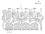
- FIG. 3 is a schematic front view of the intake side portion of the cylinder head according to the embodiment as seen from the front side of the engine.
- FIG. 2 is a schematic side view of the cylinder head of FIG. 1 viewed from the intake side (a view in the direction of arrow A in FIG. 1 ). It is a bottom view of the cylinder head of FIG.
- FIG. 2 is a cross-sectional view (cross-sectional view taken along the line BB of FIG. 1) showing the inside of an intake port of the cylinder head of FIG.
- A) is a cross-sectional view (cross-sectional view taken along the line CC of FIG. 3) showing the arrangement of the inlet and the outlet in the cylinder head of FIG. 1, and (b) shows the resin portion from FIG. 5(a).
- FIG. FIG. 6 is a cross-sectional view [cross-sectional view taken along the line DD in FIG. 5(b)] showing a configuration of a resin passage. It is the figure which expanded one of the intake ports of FIG. 4, and abbreviate
- 8A is a plan view showing an example of a core for molding an intake port
- FIG. 8B is a sectional view taken along the line EE of FIG. 8A.
- FIG. 8 is a cross-sectional view showing a discharge port and a gas passage according to a modification [a view corresponding to FIG. 5B].
- FIG. 1 is a schematic front view of an intake side portion of a cylinder head 1 according to the present embodiment as viewed from the front side of an engine
- FIG. 2 is a side view of the cylinder head 1 (a view in the direction of arrow A in FIG. 1).
- the cylinder head 1 is a component that constitutes, for example, an engine mounted on a vehicle.
- This embodiment exemplifies a cylinder head 1 of an engine in which four cylinders are arranged side by side in a row, and one cylinder is provided with two intake valves and two exhaust valves.
- the engine of the present embodiment includes a cylinder injection valve (not shown) that injects fuel into the combustion chamber 2 (see FIG. 3) and a port injection valve (not shown) that injects fuel into the intake port 3. Equipped.
- the side to which the cylinder block (not shown) is fixed with respect to the cylinder head 1 is referred to as "lower side", and the opposite side is referred to as “upper side” to determine the vertical direction of the cylinder head 1.
- the vertical direction of the cylinder head 1 does not necessarily have to match the vertical direction (vertical direction) when the engine is mounted on a vehicle or the like.
- the simple term “vertical direction” means the vertical direction of the cylinder head 1.
- 3 is a bottom view of the cylinder head 1 (a view of the cylinder head 1 viewed from the bottom surface 1b side)
- FIG. 4 is a cross-sectional view showing the inside of the intake port 3 (a cross section taken along the line BB in FIG. 1). Figure).
- the cylinder head 1 has a cylinder head body 10 formed by casting using, for example, aluminum or an aluminum alloy, and a resin portion 20 arranged along the inner surface of the intake port 3.
- the cylinder head main body 10 constitutes the main body of the cylinder head 1.
- the components other than the resin portion 20 of the cylinder head 1 (such as the above-mentioned intake port 3, the mounting holes 5 and 6 and the boss portion 8 described later) are provided in the cylinder head body 10. 2 and 4 and FIG. 5A described later, the resin portion 20 is shown with dots for easy understanding.
- the cylinder head 1 includes an intake port 3, a port injection valve mounting hole 5, a cylinder injection valve mounting hole 6, and a boss portion 8 to which a delivery pipe connected to the cylinder injection valve is fixed. It is formed for each cylinder.
- the intake port 3 and the mounting holes 5 and 6 open in the wall portion 1a of the cylinder head 1 on the intake side. Further, the boss portion 8 is provided at a position of the wall portion 1a adjacent to the mounting hole 6 of the in-cylinder injection valve.
- An intake manifold (not shown) is connected to the opening 3e (upstream end) of the intake port 3 in the wall portion 1a. 2 to 4 and FIGS. 5(a) and 5(b) which will be described later, the reference numerals of the mounting holes 5 and 6, the boss portion 8 and the like that are similarly provided in each of the four cylinders are given to only one cylinder.
- the lower surface 1b of the cylinder head 1 (hereinafter, also referred to as “cylinder head lower surface 1b") is machined into a flat surface orthogonal to the vertical direction, and serves as a joint surface with the cylinder block. As shown in FIG. 3, a combustion chamber 2 forming the upper part of the cylinder is recessed in the lower surface 1b of the cylinder head.
- the cylinder head 1 is coupled to the cylinder block with a gasket (not shown) interposed between the cylinder head lower surface 1b and the cylinder block upper surface. That is, the cylinder head lower surface 1b and the cylinder block are joined.
- the four intake ports 3 are arranged in a line.
- the direction D1 in which the four intake ports 3 are lined up is referred to as the “port side-by-side direction D1”.
- the four intake ports 3 are referred to as the first intake port 3A, the second intake port 3B, the third intake port 3C, and the fourth intake port 3D in order from the front side of the engine. ..
- the port juxtaposition direction D1 coincides with each of the front-rear direction of the engine and the cylinder row direction (direction in which the cylinders are arranged), and is orthogonal to the vertical direction.
- each intake port 3 is formed in a bifurcated shape that communicates with the combustion chamber 2 via two intake valve holes 4.
- intake air flows in a direction D2 from the opening 3e toward the intake valve hole 4.
- the flow direction D2 of the intake air is referred to as "intake direction D2".
- a center line O of the intake port 3 along the intake direction D2 is shown by a dashed line.
- the center line O corresponds to a line connecting the center points of the cross sections orthogonal to the intake direction D2 in the upstream portion of the intake port 3 relative to the bifurcated portion.
- the cylinder head 1 includes a rib portion 7 provided between the outer walls of two intake ports 3 adjacent to each other, and a seating surface 9 formed on the rib portion 7. There is.
- the rib portion 7 has a function of reinforcing the cylinder head 1. In the present embodiment, between the outer walls of the first intake port 3A and the second intake port 3B, between the outer walls of the second intake port 3B and the third intake port 3C, and between the outer walls of the third intake port 3C and the fourth intake port 3D.
- the case where the rib portion 7 is formed in each of the spaces will be exemplified.
- the seat surface 9 is provided in parallel with the cylinder head lower surface 1b between the two intake ports 3 adjacent to each other.
- the rib portion 7 between the first intake port 3A and the second intake port 3B and the rib portion 7 between the third intake port 3C and the fourth intake port 3D are integrally provided.
- the sitting surface 9 is illustrated.
- Each seat surface 9 is formed in a flat shape facing the same side (lower side) as the cylinder head lower surface 1b. Both the rib portion 7 and the seat surface 9 are arranged on the upstream side (intake manifold side) of the intake port 3 with respect to the mounting hole 6 and the boss portion 8 of the in-cylinder injection valve.
- the resin portion 20 is a heat insulating member that suppresses the heat of the cylinder head body 10 from being transferred to the intake air.
- the resin portion 20 is formed of a resin having a lower thermal conductivity than the material of the cylinder head body 10, and more preferably a resin having a high heat resistance.
- the resin portion 20 is arranged along the inner surface of the portion of the entire length of the intake port 3 excluding the portion on the intake valve hole 4 side (downstream portion).
- the resin portion 20 is formed by injection molding.
- the resin portion 21 provided between the two resin portions 20 adjacent to each other is referred to as a “connecting resin portion 21”.
- the connecting resin portion 21 is formed when the resin portion 20 is molded.
- the connecting resin part 21 of the present embodiment is disposed between the two resin parts 20 arranged in the first intake port 3A and the second intake port 3B and in the third intake port 3C and the fourth intake port 3D. It is provided between each of the two resin portions 20.
- FIG. 5A is a sectional view taken along the line CC of FIG. 3, and FIG. 5B is a view in which the resin portion 20 is omitted from FIG. 5A (that is, before the resin portion 20 is arranged). It is a cross-sectional view of the cylinder head body 10.
- the cylinder head 1 has a structure for supplying the molten resin to be the resin portion 20 to the inner surface of the intake port 3 when the resin portion 20 is injection-molded.
- a resin passage 12, a discharge port 13 and a gas passage 14 are provided.
- the two-dot chain line shown in each intake port 3 in FIG. 5B and FIG. 7 described later is a contour line of a mold used for injection molding of the resin portion 20.
- the injection port 11 is a supply port into which the tip of the injection machine 40 for injecting the molten resin is inserted to supply (inject) the molten resin.
- the exhaust port 13 is a gas vent port for expelling the gas (air) in the intake port 3 when the molten resin is injected into the injection port 11.
- Both the inlet 11 and the outlet 13 are open to the outside of the cylinder head 1.
- the outlet port 13 is provided for each intake port 3, whereas only one inlet port 11 is provided for the two intake ports 3.
- the outlet 13 is dedicated to each intake port 3, while the inlet 11 is shared by the two intake ports 3.
- the inlet 11 is specifically formed between two intake ports 3 adjacent to each other.
- the injection port 11 of the present embodiment is formed in each rib portion 7 integrally provided with the above-mentioned seat surface 9 and opens in each seat surface 9. That is, the inlet 11 is provided between the first intake port 3A and the second intake port 3B and between the third intake port 3C and the fourth intake port 3D, respectively.
- the two inlets 11 have the same circular shape.
- the resin passage 12 is a space through which the molten resin flows to the resin portion 20 when the molten resin is injected from the injection port 11.
- the resin passage 12 extends from the inlet 11 to each of the two intake ports 3 on both sides of the inlet 11. In other words, the resin passage 12 connects the inlet 11 and the intake ports 3 on both sides of the inlet 11.
- the resin passage 12 opens to the outside of the cylinder head 1 through the injection port 11 and also to the inner surface of the intake port 3.
- the opening 15 of the resin passage 12 on the inner surface of each intake port 3 is referred to as "resin inlet 15".
- the resin inlet 15 is a portion that serves as an inlet for the molten resin in the intake port 3 when the resin portion 20 is injection molded.
- the resin inlet 15 of the present embodiment has a larger opening area than the injection port 11.
- the molten resin solidified in the resin passage 12 becomes the above-mentioned connecting resin portion 21.
- the resin passage 12 of the present embodiment has an injection portion 12a that extends perpendicularly to the seat surface 9 from the injection port 11 and a distribution portion 12b that intersects the injection portion 12a and extends to the two intake ports 3. It has a T-shaped branched shape.
- the injection part 12a is a part to which the tip of the injection machine 40 is connected and the molten resin is supplied.
- the injection part 12a of the present embodiment extends straight upward from the injection port 11. That is, the injection part 12a is extended in the up-down direction between the two intake ports 3 adjacent to each other.
- the shape of the cross section (cross section perpendicular to the vertical direction) of the injection portion 12a is circular.
- the distribution part 12b is a part that distributes the molten resin flowing through the injection part 12a to the two intake ports 3. As shown in FIG. 6, the distribution portion 12b extends along the intake direction D2 between two intake ports 3 adjacent to each other, and communicates with each of the two intake ports 3 on both sides.
- the distribution portion 12b of the present embodiment extends straight along each of the port juxtaposed direction D1 and the intake direction D2.
- the cross-sectional shape along the intake direction D2 and the vertical direction is an elliptical shape having a long axis extending in the intake direction D2. That is, in the distributor 12b, the length dimension L in the intake direction D2 is set to be larger than the height dimension H in the direction orthogonal to the port juxtaposed direction D1 and the intake direction D2 (H ⁇ L). Further, in the distributor 12b of the present embodiment, the length dimension L described above is set to be larger than the width dimension W in the port juxtaposing direction D1 (see FIG. 7) (W ⁇ L).
- each outlet 13 is provided at a position different from the inlet 11.
- each injection port 11 is located closer to the intake manifold side than the mounting hole 6 and the boss portion 8 of the in-cylinder injection valve, while each discharge port 13 is more combustion chamber than the injection port 11 and the boss portion 8. It is located on the second side and opens to the cylinder head lower surface 1b.
- each inlet 11 does not overlap with the intake port 3 in the vertical direction (shifts in the port juxtaposed direction D1), whereas the outlet 13 of the present embodiment does not move vertically. It is provided so as to overlap with the intake port 3 in the direction (that is, below the intake port 3).
- the four outlets 13 have the same circular shape.
- the gas passage 14 is a space where the gas expelled from the intake port 3 flows toward the outside of the cylinder head 1 when the molten resin is injected from the injection port 11.
- the gas passage 14 extends from one intake port 3 to an exhaust port 13 provided for the intake port 3. In other words, the gas passage 14 communicates with one intake port 3 and one exhaust port 13 provided therein.
- the gas passage 14 opens to the inner surface of the intake port 3 and also to the outside of the cylinder head 1 through the exhaust port 13.
- the gas passage 14 of the present embodiment extends vertically.
- the cross section of the gas passage 14 (cross section orthogonal to the vertical direction) has a circular shape.
- the opening 16 of the gas passage 14 on the inner surface of each intake port 3 is referred to as a “resin outlet 16”.
- the resin outlet 16 is a portion serving as an outlet for gas and molten resin in the intake port 3 when the resin portion 20 is injection molded.
- FIG. 7 is an enlarged view of the fourth intake port 3D in FIG. 4 with the resin portion 20 omitted.
- the resin inlet 15 and the resin outlet 16 on the inner surface of one intake port 3 are located apart from each other (shifted) in the intake direction D2.
- the resin inlet 15 is located upstream of the resin outlet 16 in the intake direction D2.
- the resin inlet 15 and the resin outlet 16 on the inner surface of one intake port 3 are arranged so as to sandwich the above-mentioned center line O (that is, on both sides of the center line O) when viewed from above and below (for example, in a bottom view). Has been done.
- the resin inlet 15 and the resin outlet 16 of the present embodiment are located apart from each other in the port juxtaposition direction D1 and the intake direction D2 when the intake port 3 is viewed from above and below, and both A center line O is interposed between them.
- the cylinder head 1 is manufactured by the method of molding the intake port 3, the inlet 11 and the resin passage 12 in the cylinder head body 10 described above and by disposing the resin portion 20 in the intake port 3 of the cylinder head body 10. The method and will be described.
- the cylinder head body 10 is molded by casting.
- the cylinder head body 10 has an outer shape molded by a mold (not shown) (for example, an upper mold and a lower mold), and an internal space such as the intake port 3, the injection port 11 and the resin passage 12 has a shape as shown in FIG. It is molded using a core 30 as shown in (b).
- the core 30 includes an intake port portion 33 arranged at a position that becomes the intake port 3, an injection port portion 31 arranged at a position that becomes the injection port 11, and a resin passage portion arranged at a position that becomes the resin passage 12. 32 and.
- the extension portion 34 extending from the position that becomes the opening 3e of the intake port 3 in each intake port portion 33, and the connection portion 35 that connects the extension portions 34 adjacent to each other. And further.
- the extension portion 34 and the connecting portion 35 are portions arranged on the upstream side of the intake port 3 of the cylinder head body 10.
- the four intake port parts 33 are integrally provided (as one core 30) by being connected via the extending part 34 and the connecting part 35.
- the four intake port parts 33 are sequentially arranged from the front side of the engine in the order of the first intake port part 33A, the second intake port part 33B, the third intake port part 33C, and the third intake port part 33C.
- Four intake ports 3D are sequentially arranged from the front side of the engine in the order of the first intake port part 33A, the second intake port part 33B, the third intake port part 33C, and the third intake port part 33C.
- Four intake ports 3D are sequentially arranged from the front side of the engine in the order of the first intake port part 33A, the second intake port part 33B, the third intake port part 33C, and the third intake port part 33C.
- Four intake ports 3D are sequentially arranged from the front side of the engine in the
- the inlet 11 and the resin passage 12 of the present embodiment are provided between the first intake port 3A and the second intake port 3B and between the third intake port 3C and the fourth intake port 3D, respectively. Will be placed. Therefore, in the core 30, the injection port portion 31 and the resin passage portion 32 are provided between the first intake port portion 33A and the second intake port portion 33B and between the third intake port portion 33C and the fourth intake port portion 33D. It is located in two places, the room and the room.
- the resin passage portion 32 includes an injection core portion 32a arranged at a position to be the injection portion 12a and a distribution core portion 32b arranged at a position to be the distribution portion 12b.
- the distribution unit 12b that communicates the first intake port 3A and the second intake port 3B and the distribution unit 12b that communicates the third intake port 3C and the fourth intake port 3D are provided. It is provided. Therefore, in the core 30, the first intake port portion 33A and the second intake port portion 33B are connected by the distribution core portion 32b, and the third intake port portion 33C and the fourth intake port portion 34D are also distributed core portion 32b. Are connected by.
- the cylinder head body 10 is molded by pouring a molten metal obtained by melting a material (for example, aluminum or an aluminum alloy) to be the cylinder head body 10 from the spout while the core 30 is placed inside the mold and solidifying the molten metal. To be done.
- a material for example, aluminum or an aluminum alloy
- the resin portion 20 is formed by injection molding. Specifically, first, a mold is arranged in the intake port 3 of the cylinder head main body 10 (see the chain double-dashed line in FIG. 5(b) and FIG. 7), and a space for supplying the molten resin is defined as an inner surface of the intake port 3. Partition with the outer surface of the mold. Next, the tip of the injection machine 40 is inserted into the injection port 11, and the molten resin is injected from the injection machine 40 into the injection portion 12 a of the resin passage 12.
- the molten resin injected into the injection part 12a is supplied to each inner surface of the two intake ports 3 through the distribution part 12b.
- the molten resin flows along the inner surface of the intake port 3 and spreads into the space between the inner surface of the intake port 3 and the outer surface of the mold.
- the gas in the intake port 3 is expelled toward the outside of the cylinder head body 10 through the gas passage 14 and is exhausted from the exhaust port 13.
- the injection of the molten resin into the injection port 11 is stopped. Then, when the molten resin is solidified, the resin portion 20 is formed in the intake port 3 and the connecting resin portion 21 is formed in the resin passage 12. After that, the cylinder head 1 is completed by removing the mold arranged in the intake port 3.
- the injection port 11 is provided between the two intake ports 3 adjacent to each other, and the resin passage 12 extends from the injection port 11 to each of the intake ports 3 on both sides. Therefore, when the resin portion 20 is molded, if the molten resin is injected into one inlet 11, the molten resin can be supplied to the inner surfaces of the two intake ports 3 through the resin passage 12. That is, the injection port 11 for the molten resin can be shared by the two intake ports 3. Therefore, the number of the injection ports 11 can be reduced as compared with the configuration in which the injection ports 11 are provided for each intake port 3. That is, since the injection port 11 can be efficiently arranged in the narrow space of the cylinder head 1, it is possible to avoid increasing the size of the cylinder head 1. In addition, the degree of freedom in the shape and arrangement of each injection port 11 can be increased.
- the resin portion 20 since the resin portion 20 is arranged in the intake port 3, the resin portion 20 functions as a heat insulating material between the inner surface of the intake port 3 and the intake air flowing in the intake port 3. As a result, the heat transferred from the inner surface of the intake port 3 to the intake air is reduced, so that the temperature rise of the intake air can be suppressed. Therefore, the reduction of the intake air amount and the occurrence of knocking can be suppressed, and the engine performance can be improved.
- the resin passage 12 is extended to each of the two intake ports 3, in the state where the molding of the resin portion 20 is completed, the resin solidified in the resin passage 12 between the two intake ports 3 (the connecting resin portion). 21) is arranged. Thereby, the heat insulating effect between the intake ports 3 can be enhanced. Therefore, according to the cylinder head 1 described above, since the temperature rise of the intake air can be suppressed also from this point, the decrease of the intake air amount and the occurrence of knocking can be suppressed, and the engine performance can be improved. ..
- the resin passage 12 is provided, so that in the core 30 used for casting the intake port 3 and the resin passage 12, two intake port portions 33 are connected to each other by the resin passage portion 32. That is, in the core 30, the two intake port portions 33 adjacent to each other can be connected not only by the extension portion 34 and the connecting portion 35 but also by the resin passage portion 32. As a result, the positional relationship between the intake port portions 33 is easily maintained, so that the shape of the core 30 can be stabilized. Therefore, the positional accuracy of the intake port 3 in the cylinder head 1 can be improved.
- the injection port 11 is opened to the seat surface 9 parallel to the cylinder head lower surface 1b and the resin passage 12 has the injection portion 12a extending from the injection port 11 perpendicularly to the seat surface 9, the molten resin
- the seat surface 9 can be horizontally arranged and the injecting portion 12 can be vertically extended.
- the resin passage 12 has the distribution portion 12b extending between the two intake ports 3 adjacent to each other along the intake direction D2 and communicating with each of these intake ports 3, the molding of the resin portion 20 is completed.
- the resin (connecting resin portion 21) extending along the intake direction D2 can be arranged between the two intake ports 3.
- the heat insulating effect between the intake ports 3 can be enhanced in the intake direction D2.
- the two intake port portions 33 since the two intake port portions 33 are connected by the distribution core portion 32b, the two intake port portions 33 can be connected over a wide range along the intake direction D2. This makes it easier to maintain the positional relationship between the intake port portions 33, so that the shape of the core 30 can be further stabilized and the positional accuracy of the intake port 3 in the cylinder head 1 can be further improved. ..
- the inlet 11 is formed in the rib portion 7 provided between the outer walls of the two intake ports 3 adjacent to each other, the rib portion 7 can reinforce the space between the intake ports 3 and the rib portion 7 Can be utilized as a pedestal portion of the injection port 11. As a result, the space efficiency is improved as compared with the case where a dedicated pedestal portion is provided in the injection port 11, so that the strength and rigidity around the intake port 3 can be increased while suppressing an increase in the size of the cylinder head 1.
- the exhaust port 13 Since the exhaust port 13 is formed at a position different from the injection port 11 and the gas passage 14 extends from the intake port 3 to the exhaust port 13, the inside of the intake port 3 is filled when the molten resin is injected into the injection port 11. This gas can be discharged to the outside through the gas passage 14 and the discharge port 13. Thereby, the molten resin can be more smoothly supplied into the intake port 3. Further, since the resin inlet 15 and the resin outlet 16 are located apart from each other in the intake direction D2 on the inner surface of the intake port 3, the molten resin may flow in the process of flowing from the resin inlet 15 toward the resin outlet 16. Can be made to flow in the intake direction D2 along the inner surface of the intake port 3. Thereby, the molten resin can be easily spread in the intake direction D2. Therefore, the resin portion 20 can be easily molded.
- the resin inlet 15 and the resin outlet 16 are arranged so as to sandwich the center line O along the intake direction D2 of the intake port 3 when viewed from above and below, so that the molten resin is filled with the resin inlet 15
- the molten resin can be made to flow in the port side-by-side direction D1 along the inner surface of the intake port 3 while flowing from the direction toward the resin outlet 16. Thereby, the molten resin can be easily spread in the port parallel direction D1. Therefore, the resin portion 20 can be more easily molded.
- the inlet 11 can be easily arranged closer to the upstream side (intake manifold side). This makes it easier to dispose the injection port 11 apart from the configuration such as the mounting hole 6 and the boss portion 8 of the in-cylinder injection valve provided in the cylinder head 1. That is, since the injection port 11 can be efficiently arranged, interference between the injection port 11 and other components can be easily avoided.
- the discharge port 13 Since the discharge port 13 is open to the cylinder head lower surface 1b, it is possible to process the discharge port 13 at the same time as the cylinder head lower surface 1b is processed when the cylinder head 1 is manufactured. As a result, the processing of the discharge port 13 is facilitated, and the manufacturing cost can be reduced.
- the opening area of the resin inlet 15 is larger than the opening area of the inlet 11, the molten resin injected from the inlet 11 can be more smoothly supplied from the resin inlet 15 into the intake port 3. Therefore, the resin portion 20 can be more easily molded.
- the configuration of the cylinder head 1 described above is an example and is not limited to the above. For example, it may not be the cylinder head of an in-line four-cylinder engine, or the cylinder head of an engine equipped with both an in-cylinder injection valve and a port injection valve.
- the shape of the intake port 3 is not limited to the bifurcated shape described above. Further, the rib portion 7 and the boss portion 8 may be omitted.
- the configuration of the core 30 described above is an example.
- the core 30 may further have a portion arranged at a position to be the discharge port 13 and the gas passage 14. Further, the extending portion 34 and the connecting portion 35 may be omitted.
- the inlet 11, the resin passage 12, the outlet 13, and the gas passage 14 are not limited to those formed by using the core, and may be formed by, for example, drilling.
- the position and the number of the injection ports 11 are not limited to those described above.
- the inlet 11 may be provided between the two intake ports 3 adjacent to each other, and may be provided, for example, between the second intake port 3B and the third intake port 3C described above. Further, in the above-described embodiment, the case where one inlet 11 is provided for the two intake ports 3 is illustrated, but one inlet 11 may be provided for three or more intake ports 3. Good.
- the inlet 11 is provided between the second intake port 3B and the third intake port 3C, and the first intake port 3A and the second intake port 3B, and the third intake port 3C and the fourth intake port 3D are respectively described above.
- the molten resin can be supplied from one injection port 11 to each of the four intake ports 3 by connecting the same with the distribution unit 12a. In this case, the number of injection ports 11 in the cylinder head 1 can be reduced to one.
- the position and the number of the discharge ports 13 are not limited to those described above.
- the outlet 13 may be shared by the plurality of intake ports 3 in the same manner as the inlet 11 is shared by the plurality of intake ports 3.
- the exhaust ports 13 provided for each of the second intake port 3B and the third intake port 3C described above may be integrated into one exhaust port 13'. More specifically, the exhaust port 13' is formed between the second intake port 3B and the third intake port 3C which are adjacent to each other, and the second intake port 3B and the third intake port 3C (that is, both sides of the exhaust port 13' are formed.
- the gas passage 14' may extend from each of the intake ports 3) to the exhaust port 13'.
- the gas in the two intake ports 3 can be collectively discharged from one exhaust port 13'. That is, in the two intake ports 3, the gas outlet 13' can be shared. Therefore, the number of the exhaust ports 13 and 13' can be reduced as compared with the configuration in which the exhaust port 13 is provided for each intake port 3. As a result, the narrow space of the cylinder head 1 can be used more efficiently, the cylinder head 1 can be prevented from becoming larger, and the flexibility of the shape and arrangement of the individual discharge ports 13, 13' can be increased.
- the arrangement of the resin inlet 15 and the resin outlet 16 described above is an example.
- the resin inlet 15 may be located downstream of the resin outlet 16 in the intake direction D2.
- the shapes of the resin passage 12 and the gas passage 14 are not limited to those described above.
- the injection portion 12a of the resin passage 12 may extend obliquely with respect to the vertical direction or may be curved.
- the distribution portion 12b of the resin passage 12 may have a circular cross-sectional shape, or may have a shape other than a circular shape or an oval shape, depending on the characteristics of the resin.
- the size relationship among the length dimension L, the width dimension W, and the height dimension H of the distribution portion 12b is not limited to the above.
- Cylinder head 1b Lower surface (Cylinder head lower surface) 2 Combustion chamber 3 Intake port 7 Rib portion 9 Seat surface 10 Cylinder head body 11 Injection port 12 Resin passage 12a Injection portion 12b Distribution portion 13, 13' Discharge port 14, 14' Gas passage 15 Resin inlet (opening of resin passage) 16 Resin outlet (opening of gas passage) 20 Resin part
Landscapes
- Engineering & Computer Science (AREA)
- Chemical & Material Sciences (AREA)
- Combustion & Propulsion (AREA)
- Mechanical Engineering (AREA)
- General Engineering & Computer Science (AREA)
- Cylinder Crankcases Of Internal Combustion Engines (AREA)
Abstract
L'invention concerne une culasse (1) qui comprend : une pluralité d'orifices d'admission parallèles (3) qui communiquent avec une chambre de combustion d'un moteur à cylindres multiples; et des parties de résine (20) qui sont agencées le long de surfaces internes des orifices d'admission (3). La culasse (1) comprend : des orifices d'injection (11) qui s'ouvrent vers l'extérieur entre deux orifices d'admission adjacents (3); et des passages de résine (12) qui s'étendent depuis les orifices d'injection (11) vers chacun des deux orifices d'admission (3) et permettent à de la résine fondue de s'écouler vers les parties de résine (20) lorsque la résine fondue est injectée à partir des orifices d'injection (11).
Priority Applications (1)
| Application Number | Priority Date | Filing Date | Title |
|---|---|---|---|
| JP2020565700A JP7136232B2 (ja) | 2019-01-07 | 2019-12-25 | シリンダヘッド |
Applications Claiming Priority (2)
| Application Number | Priority Date | Filing Date | Title |
|---|---|---|---|
| JP2019-000831 | 2019-01-07 | ||
| JP2019000831 | 2019-01-07 |
Publications (1)
| Publication Number | Publication Date |
|---|---|
| WO2020145155A1 true WO2020145155A1 (fr) | 2020-07-16 |
Family
ID=71521363
Family Applications (1)
| Application Number | Title | Priority Date | Filing Date |
|---|---|---|---|
| PCT/JP2019/050942 Ceased WO2020145155A1 (fr) | 2019-01-07 | 2019-12-25 | Culasse |
Country Status (2)
| Country | Link |
|---|---|
| JP (1) | JP7136232B2 (fr) |
| WO (1) | WO2020145155A1 (fr) |
Citations (10)
| Publication number | Priority date | Publication date | Assignee | Title |
|---|---|---|---|---|
| JPH0269043U (fr) * | 1988-11-14 | 1990-05-25 | ||
| JPH0341151U (fr) * | 1989-08-28 | 1991-04-19 | ||
| US5842342A (en) * | 1997-02-21 | 1998-12-01 | Northrop Grumman Corporation | Fiber reinforced ceramic matrix composite internal combustion engine intake/exhaust port liners |
| JPH11182367A (ja) * | 1997-12-15 | 1999-07-06 | Toyota Motor Corp | 樹脂製インテークマニホールド |
| JP2011094515A (ja) * | 2009-10-28 | 2011-05-12 | Toyoda Gosei Co Ltd | シリンダヘッドブロック |
| JP2014008638A (ja) * | 2012-06-28 | 2014-01-20 | Aisan Ind Co Ltd | デリバリパイプの成形方法 |
| WO2015093256A1 (fr) * | 2013-12-19 | 2015-06-25 | 東洋製罐グループホールディングス株式会社 | Procédé de moulage de plastique |
| JP2016205267A (ja) * | 2015-04-24 | 2016-12-08 | 三菱自動車工業株式会社 | シリンダヘッドのポート部の製造方法 |
| JP2018003602A (ja) * | 2016-06-27 | 2018-01-11 | 三菱自動車工業株式会社 | エンジンの吸気通路構造 |
| JP2018003601A (ja) * | 2016-06-27 | 2018-01-11 | 三菱自動車工業株式会社 | エンジンの吸気通路構造 |
-
2019
- 2019-12-25 JP JP2020565700A patent/JP7136232B2/ja active Active
- 2019-12-25 WO PCT/JP2019/050942 patent/WO2020145155A1/fr not_active Ceased
Patent Citations (10)
| Publication number | Priority date | Publication date | Assignee | Title |
|---|---|---|---|---|
| JPH0269043U (fr) * | 1988-11-14 | 1990-05-25 | ||
| JPH0341151U (fr) * | 1989-08-28 | 1991-04-19 | ||
| US5842342A (en) * | 1997-02-21 | 1998-12-01 | Northrop Grumman Corporation | Fiber reinforced ceramic matrix composite internal combustion engine intake/exhaust port liners |
| JPH11182367A (ja) * | 1997-12-15 | 1999-07-06 | Toyota Motor Corp | 樹脂製インテークマニホールド |
| JP2011094515A (ja) * | 2009-10-28 | 2011-05-12 | Toyoda Gosei Co Ltd | シリンダヘッドブロック |
| JP2014008638A (ja) * | 2012-06-28 | 2014-01-20 | Aisan Ind Co Ltd | デリバリパイプの成形方法 |
| WO2015093256A1 (fr) * | 2013-12-19 | 2015-06-25 | 東洋製罐グループホールディングス株式会社 | Procédé de moulage de plastique |
| JP2016205267A (ja) * | 2015-04-24 | 2016-12-08 | 三菱自動車工業株式会社 | シリンダヘッドのポート部の製造方法 |
| JP2018003602A (ja) * | 2016-06-27 | 2018-01-11 | 三菱自動車工業株式会社 | エンジンの吸気通路構造 |
| JP2018003601A (ja) * | 2016-06-27 | 2018-01-11 | 三菱自動車工業株式会社 | エンジンの吸気通路構造 |
Also Published As
| Publication number | Publication date |
|---|---|
| JP7136232B2 (ja) | 2022-09-13 |
| JPWO2020145155A1 (ja) | 2021-09-27 |
Similar Documents
| Publication | Publication Date | Title |
|---|---|---|
| CN101400462B (zh) | 用于制造气缸盖的方法以及气缸盖 | |
| CN103775234B (zh) | 气缸盖的水套结构 | |
| US7100559B2 (en) | Engine air intake manifold | |
| JP6624102B2 (ja) | エンジンのシリンダヘッド | |
| CN103775235B (zh) | 气缸盖的水套结构 | |
| CN103775230A (zh) | 气缸盖的水套结构 | |
| US10975812B2 (en) | Method and system for manufacturing a family of intake manifolds for a family of internal combustion engines | |
| JP2018184939A (ja) | 内燃機関の冷却構造 | |
| JP2014084738A (ja) | シリンダヘッドの冷却液通路構造 | |
| WO2020145155A1 (fr) | Culasse | |
| JP2004270588A (ja) | エンジンの吸気装置 | |
| JP7136233B2 (ja) | シリンダヘッド | |
| JP3622445B2 (ja) | 直噴式内燃機関のシリンダヘッド製造方法 | |
| JP3618593B2 (ja) | 内燃機関におけるシリンダヘッドの構造 | |
| JP2018028268A (ja) | インテークマニホールド | |
| JP7040645B2 (ja) | シリンダヘッド | |
| JP7173166B2 (ja) | シリンダヘッド | |
| WO2020145158A1 (fr) | Culasse | |
| JP7491656B2 (ja) | 吸気マニホールド | |
| JPH10169504A (ja) | 内燃機関のシリンダヘッド | |
| CN107002592A (zh) | 汽缸盖和具备该汽缸盖的内燃机以及汽缸盖的制造方法 | |
| JP5782728B2 (ja) | 内燃機関の吸気構造 | |
| JPH10280954A (ja) | シリンダヘッドの冷却構造 |
Legal Events
| Date | Code | Title | Description |
|---|---|---|---|
| 121 | Ep: the epo has been informed by wipo that ep was designated in this application |
Ref document number: 19908294 Country of ref document: EP Kind code of ref document: A1 |
|
| ENP | Entry into the national phase |
Ref document number: 2020565700 Country of ref document: JP Kind code of ref document: A |
|
| NENP | Non-entry into the national phase |
Ref country code: DE |
|
| 122 | Ep: pct application non-entry in european phase |
Ref document number: 19908294 Country of ref document: EP Kind code of ref document: A1 |