WO2020145204A1 - Appareil et procédé de production de plaque d'électrode pour batterie - Google Patents
Appareil et procédé de production de plaque d'électrode pour batterie Download PDFInfo
- Publication number
- WO2020145204A1 WO2020145204A1 PCT/JP2019/051460 JP2019051460W WO2020145204A1 WO 2020145204 A1 WO2020145204 A1 WO 2020145204A1 JP 2019051460 W JP2019051460 W JP 2019051460W WO 2020145204 A1 WO2020145204 A1 WO 2020145204A1
- Authority
- WO
- WIPO (PCT)
- Prior art keywords
- slurry
- valve
- manifold
- opening
- adjusting
- Prior art date
- Legal status (The legal status is an assumption and is not a legal conclusion. Google has not performed a legal analysis and makes no representation as to the accuracy of the status listed.)
- Ceased
Links
Images






Classifications
-
- B—PERFORMING OPERATIONS; TRANSPORTING
- B05—SPRAYING OR ATOMISING IN GENERAL; APPLYING FLUENT MATERIALS TO SURFACES, IN GENERAL
- B05C—APPARATUS FOR APPLYING FLUENT MATERIALS TO SURFACES, IN GENERAL
- B05C11/00—Component parts, details or accessories not specifically provided for in groups B05C1/00 - B05C9/00
- B05C11/10—Storage, supply or control of liquid or other fluent material; Recovery of excess liquid or other fluent material
-
- B—PERFORMING OPERATIONS; TRANSPORTING
- B05—SPRAYING OR ATOMISING IN GENERAL; APPLYING FLUENT MATERIALS TO SURFACES, IN GENERAL
- B05C—APPARATUS FOR APPLYING FLUENT MATERIALS TO SURFACES, IN GENERAL
- B05C5/00—Apparatus in which liquid or other fluent material is projected, poured or allowed to flow on to the surface of the work
- B05C5/02—Apparatus in which liquid or other fluent material is projected, poured or allowed to flow on to the surface of the work the liquid or other fluent material being discharged through an outlet orifice by pressure, e.g. from an outlet device in contact or almost in contact, with the work
-
- B—PERFORMING OPERATIONS; TRANSPORTING
- B05—SPRAYING OR ATOMISING IN GENERAL; APPLYING FLUENT MATERIALS TO SURFACES, IN GENERAL
- B05D—PROCESSES FOR APPLYING FLUENT MATERIALS TO SURFACES, IN GENERAL
- B05D1/00—Processes for applying liquids or other fluent materials
- B05D1/26—Processes for applying liquids or other fluent materials performed by applying the liquid or other fluent material from an outlet device in contact with, or almost in contact with, the surface
-
- B—PERFORMING OPERATIONS; TRANSPORTING
- B05—SPRAYING OR ATOMISING IN GENERAL; APPLYING FLUENT MATERIALS TO SURFACES, IN GENERAL
- B05D—PROCESSES FOR APPLYING FLUENT MATERIALS TO SURFACES, IN GENERAL
- B05D3/00—Pretreatment of surfaces to which liquids or other fluent materials are to be applied; After-treatment of applied coatings, e.g. intermediate treating of an applied coating preparatory to subsequent applications of liquids or other fluent materials
-
- B—PERFORMING OPERATIONS; TRANSPORTING
- B05—SPRAYING OR ATOMISING IN GENERAL; APPLYING FLUENT MATERIALS TO SURFACES, IN GENERAL
- B05D—PROCESSES FOR APPLYING FLUENT MATERIALS TO SURFACES, IN GENERAL
- B05D7/00—Processes, other than flocking, specially adapted for applying liquids or other fluent materials to particular surfaces or for applying particular liquids or other fluent materials
-
- H—ELECTRICITY
- H01—ELECTRIC ELEMENTS
- H01M—PROCESSES OR MEANS, e.g. BATTERIES, FOR THE DIRECT CONVERSION OF CHEMICAL ENERGY INTO ELECTRICAL ENERGY
- H01M4/00—Electrodes
- H01M4/02—Electrodes composed of, or comprising, active material
- H01M4/04—Processes of manufacture in general
-
- H—ELECTRICITY
- H01—ELECTRIC ELEMENTS
- H01M—PROCESSES OR MEANS, e.g. BATTERIES, FOR THE DIRECT CONVERSION OF CHEMICAL ENERGY INTO ELECTRICAL ENERGY
- H01M4/00—Electrodes
- H01M4/02—Electrodes composed of, or comprising, active material
- H01M4/13—Electrodes for accumulators with non-aqueous electrolyte, e.g. for lithium-accumulators; Processes of manufacture thereof
- H01M4/139—Processes of manufacture
-
- Y—GENERAL TAGGING OF NEW TECHNOLOGICAL DEVELOPMENTS; GENERAL TAGGING OF CROSS-SECTIONAL TECHNOLOGIES SPANNING OVER SEVERAL SECTIONS OF THE IPC; TECHNICAL SUBJECTS COVERED BY FORMER USPC CROSS-REFERENCE ART COLLECTIONS [XRACs] AND DIGESTS
- Y02—TECHNOLOGIES OR APPLICATIONS FOR MITIGATION OR ADAPTATION AGAINST CLIMATE CHANGE
- Y02E—REDUCTION OF GREENHOUSE GAS [GHG] EMISSIONS, RELATED TO ENERGY GENERATION, TRANSMISSION OR DISTRIBUTION
- Y02E60/00—Enabling technologies; Technologies with a potential or indirect contribution to GHG emissions mitigation
- Y02E60/10—Energy storage using batteries
Definitions
- the present invention relates to a manufacturing apparatus for manufacturing a battery electrode plate by applying a slurry containing an active material to a base material, and a battery electrode plate manufacturing method.
- a battery electrode plate used in a lithium-ion battery or the like is manufactured by applying a slurry containing an active material, a binder, a conductive auxiliary agent and a solvent to a base material sent by roll-to-roll.
- the thickness of the layer containing the active material formed on the base material directly affects the charge/discharge amount of the battery, and thus, particularly in a high-capacity battery ( In the case of a battery), it is very important to control the film thickness of the slurry applied to the base material. That is, the slurry needs to be applied with a uniform thickness along the width direction and the feed direction of the base material.
- the die in addition to a discharge port for discharging the slurry to the base material, the die discharges the slurry in front of the discharge port to allow the slurry to flow from the discharge port.
- a plurality of adjusting portions for adjusting the discharge amount of the die are provided across the width direction of the die, and the slurry applied to the base material has a uniform thickness along the width direction of the base material so that the slurry in the width direction of the die The distribution of the discharge amount of is finely adjusted.
- the slurry discharged from the die may include a large amount of an organic solvent such as alcohol as a solvent, and by continuing the discharge of the slurry from the die, the inside and the periphery of the manufacturing apparatus is an organic solvent volatilized from the slurry. May fill up.
- an organic solvent such as alcohol as a solvent
- the adjusting unit is driven for adjusting the discharge amount of the slurry from the discharge port, for example, when the opening degree of the valve forming the adjusting unit is adjusted by the motor
- the motor serves as an ignition source, and a slight spark generated by driving the motor may cause an explosion in the manufacturing apparatus.
- the electrical equipment associated with it also corresponds to the ignition source.
- the present invention has been made in view of the above problems, the thickness of the coating layer formed on the substrate without causing an explosion even when using a slurry containing a large amount of organic solvent It is an object of the present invention to provide an apparatus for manufacturing a battery electrode plate and a method for manufacturing a battery electrode plate that can make the temperature uniform.
- the battery electrode plate manufacturing apparatus of the present invention is connected to a first manifold, which is long in the width direction and has a space for accumulating the slurry, and the first manifold via a slit that is wide in the width direction, and the slurry is used as a base material.
- a die formed with a discharge port for discharging to the first manifold, and a supply means for supplying a slurry to the first manifold from an inflow portion communicating with the first manifold, and the die of the slit.
- a plurality of adjusting valves for adjusting the discharge amount of the slurry from the discharge port by causing the slurry to flow out or flow in are provided in plural in the width direction.
- the adjustment valve the opening degree of the valve is adjusted by the change of the internal pressure due to the flow of fluid, and the outflow amount or the inflow amount of the slurry from the adjustment valve is adjusted by adjusting the opening degree of the valve,
- An opening degree sensor for measuring the opening degree of the valve is detachably provided, and the opening degree sensor is removed from the adjusting valve when the slurry is discharged from the die.
- the thickness of the coating layer formed on the substrate is uniform without causing an explosion.
- a slurry containing a large amount of an organic solvent is used, the thickness of the coating layer formed on the substrate is uniform without causing an explosion.
- the width direction distribution of the discharge amount of the slurry from the discharge port of the die so that the coating layer has a uniform thickness. it can.
- the opening degree of the valve is adjusted by the change of the internal pressure due to the inflow and outflow of the fluid, and the outflow amount or the inflow amount of the slurry from the adjustment valve is adjusted by adjusting the opening degree of the valve
- the adjusting valve can be configured to have no electrical components, and can be prevented from becoming an ignition source. Further, since the opening sensor is removed from the adjusting valve when discharging the slurry from the die, it is possible to discharge the slurry to the base material in the absence of the opening sensor that can be an ignition source. it can.
- the fluid may be a non-flammable gas.
- the fluid may be a non-flammable liquid.
- the adjustment valve has a moving end that moves with a change in the opening of the valve, and the opening sensor is a displacement sensor that detects the position of the moving end.
- the opening sensor may be provided in each of the adjusting valves.
- it further has a film thickness sensor for measuring the film thickness of the coating film layer of the slurry discharged onto the base material, and at the time of discharging the slurry from the die onto the base material, the measurement result by the film thickness sensor is constantly fed back. Therefore, it is preferable that the opening of the valve is constantly controlled.
- the slurry stored in the first manifold formed in the die and long in the width direction is passed through the slits wide in the width direction, and then the first manifold.
- a method of manufacturing an electrode plate for a battery which is performed by discharging from a discharge port connected to, and applying to a base material, wherein slurry is allowed to flow out between the first manifold of the slit and the discharge port,
- a plurality of adjusting valves for adjusting the discharge amount of the slurry from the discharge port by inflowing are provided in the width direction, and the adjusting valve has an opening degree of the valve due to a change in internal pressure due to the inflow and outflow of a fluid.
- the outflow amount or inflow amount of the slurry from the control valve is adjusted by adjusting the opening of the valve, the opening sensor for measuring the opening of the valve is detachably provided, The discharge of the slurry from the die is stopped, and in a state in which the opening sensor is attached to the adjustment valve, the opening of the valve is adjusted by the value of the internal pressure of the adjustment valve and the measured value of the opening sensor.
- the thickness of the coating layer formed on the substrate is uniform without causing an explosion.
- a slurry containing a large amount of an organic solvent is used, even if a slurry containing a large amount of an organic solvent is used, the thickness of the coating layer formed on the substrate is uniform without causing an explosion.
- the width direction distribution of the discharge amount of the slurry from the discharge port of the die so that the coating layer has a uniform thickness. it can.
- the opening degree of the valve is adjusted by the change of the internal pressure due to the inflow and outflow of the fluid, and the outflow amount or the inflow amount of the slurry from the adjustment valve is adjusted by adjusting the opening degree of the valve
- the adjusting valve can be configured to have no electrical components, and can be prevented from becoming an ignition source.
- a calibration curve of the opening of the valve is obtained by the value of the internal pressure of the adjusting valve and the measured value of the opening sensor.
- the present invention even when a slurry containing a large amount of an organic solvent is used, it is possible to make the thickness of the coating layer formed on the base material uniform without causing an explosion.
- FIG. 1A is a cross-sectional view taken along the arrow b in FIG. 1
- FIG. 1B is a plan view of the shim plate 15.
- FIG. 1B is a plan view of the shim plate 15.
- (A) is an explanatory view showing a schematic configuration of a regulating valve at the time of discharging the slurry
- (B) is a graph showing a calibration curve between the opening of the valve and the flow rate of the slurry. It is explanatory drawing which shows schematic structure of the modification of a regulation valve. It is an example of forming a coating layer by the manufacturing apparatus of the electrode plate for a battery of the present invention.
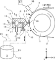
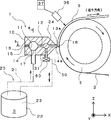
- FIG. 1 is an explanatory diagram showing a schematic configuration of a battery electrode plate manufacturing apparatus according to an embodiment of the present invention.
- the manufacturing apparatus 1 is an apparatus for applying a slurry 3 containing an active material, a binder, a conductive auxiliary agent and a solvent to a base material 2 made of a metal foil which is sent by roll-to-roll. According to this manufacturing apparatus, a coating layer containing an active material is formed on the base material 2 by drying the applied slurry 3, and the base material 2 is cut into a predetermined shape to form a battery electrode plate.
- the film of the coating layer formed by the slurry 3 applied to the base material 2 is formed. Thickness control is very important, and according to the manufacturing apparatus 1, the slurry 3 has a uniform thickness (uniform coating amount) along the feeding direction of the substrate 2, as described in the following embodiments. ) Is applied.
- the width direction of the base material 2 is a direction orthogonal to the feeding direction of the base material 2, and the Y-axis direction in FIG. 1 corresponds to this.
- the manufacturing apparatus 1 includes a die 10 configured to be long along the width direction of the base material 2, and a supply unit 20 that supplies the slurry 3 to the die 10.
- the longitudinal direction (Y-axis direction in FIG. 1) is called the width direction.
- the roller 5 facing the die 10 is installed, and the width direction of the die 10 and the direction of the rotation center line of the roller 5 are parallel to each other.
- the base material 2 is guided by the roller 5, and the gap (gap) between the base material 2 and the die 10 (the tip of the slit 12 described later) is kept constant, and the slurry 3 is applied in this state.
- the die 10 of the present embodiment includes a first divided body 13 having a first lip 13a having a tapered shape and a second divided body 14 having a second lip 14a having a tapered shape, and a shim plate 15 interposed therebetween. It is composed by sandwiching the two.
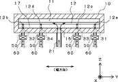
- FIG. 2 is a sectional view taken along the arrow a in FIG. 3A is a sectional view taken along the arrow b in FIG. 1, and the shim plate 15 is shown in FIG. 3B.
- the die 10 is provided with a first manifold 11 having a space that is long in the width direction and a slit 12 connected to the first manifold 11, and the die 10 includes a first lip 13a and a second lip 14a.
- a discharge port 18 which is an open end of the slit 12 is formed between them. That is, the first manifold 11 and the discharge port 18 are connected via the slit 12.
- the slurry 3 supplied by the supply means 20 is first accumulated in the first manifold 11, and then discharged from the discharge port 18 via the slit 12.
- the slit 12 is formed to be long in the width direction similarly to the first manifold 11, and the size of the slit 12 in the width direction is a substantially U-shape formed of the main body portion 15a, the protruding piece 15b, and the protruding piece 15c.
- the slurry 3 having a widthwise dimension substantially the same as the widthwise dimension of the slit 12 and determined by the inner dimension W of the shim plate 15 (see FIG. 3B) can be applied onto the base material 2.
- the clearance dimension (height dimension) of the slit 12 is 0.4 to 1.5 mm, for example.
- the die 10 is installed in a posture in which the gap direction of the slit 12 is the vertical direction and the width direction is the horizontal direction.
- the die 10 is installed in a posture in which the first manifold 11 and the slit 12 are arranged side by side in the horizontal direction. Therefore, the direction in which the slurry 3 stored in the first manifold 11 flows to the substrate 2 through the slit 12 and the discharge port 18 is horizontal.
- the pressure inside the first manifold 11 (coating pressure) can be adjusted by changing the thickness of the shim plate 15. By this adjustment, the slurry 3 having various characteristics can have a uniform film thickness. Can be applied.
- An inflow part 16 is provided in the center of the die 10 in the width direction, and the inflow part 16 is formed of a through hole (inflow port) connected to the first manifold 11 from the outside of the die 10.
- the supply means 20 supplies the inflow pipe 21 whose one end is connected to the inflow part 16, the tank 22 storing the slurry 3, and the slurry 3 in the tank 22 to the die 10 through the pipe 21. And a pump 23 for.
- the supply unit 20 can supply the slurry 3 to the first manifold 11 from the inflow section 16.
- the inflow part 16 is connected to the bottom part 17 of the first manifold 11, and the slurry 3 is allowed to flow in from the bottom part 17.
- the first manifold 11 can store the slurry 3 supplied from the supply means 20, and the slurry 3 stored in the first manifold 11 passes through the slit 12 and is rolled to roll from the discharge port 18.
- the slurry 3 can be continuously applied to the base material 2 by being discharged onto the base material 2 sent by.
- the gap size of the slit 12 is constant in the width direction, and the thickness of the slurry 3 applied on the base material 2 is constant in the width direction.
- the die 10 is provided with a pressure sensor (not shown), and this pressure sensor measures the internal pressure of the slurry 3 in the first manifold 11. Then, the supply of the slurry 3 by the supply means 20 is controlled based on the measurement result, and the internal pressure of the slurry 3 in the first manifold 11 is kept constant.
- the slurry 3 having a constant internal pressure in the first manifold 11 is discharged from the slit 12 in an equal amount over the entire length in the width direction, and the slurry 3 discharged from the slit 12 based on the measurement result of the pressure sensor. Is controlled so as not to fluctuate, and the thickness of the slurry 3 applied on the base material 2 in the feed direction is made constant.
- a filter for the slurry 3 is provided in the middle of the pipe 21.
- 33, 34 are provided.
- the first and second adjusting portions 31 and 32 are provided at both ends 12a and 12b of the slit 12 in the width direction, and the first and second adjusting portions 31 and 32 are provided at intermediate portions 12c and 12d between the both ends 12a and 12b. 3 and a fourth adjusting portion 33, 34 are provided.
- the adjusting parts 31, 32, 33, 34 include a through hole connecting the slit 12 and the outside of the die 10, a pipe 50 connected to the through hole, and an adjusting valve 60 described later.
- one end of the pipe 50 is connected to the tank 22, and in addition to the slurry 3 stored in the tank 22 flowing into the first manifold 11 from the inflow section 16, the adjusting sections 31, 32, It flows into the slit 12 from 33 and 34.
- the slurry 3 that has flowed out of these adjusting units 31, 32, 33, 34 is returned to the tank 22.
- a filter (not shown) is preferably provided in the middle of the pipe 50.
- the adjusting parts 31, 32, 33, 34 for allowing the slurry 3 of the first manifold 11 to flow into the slit 12 of the die 10 from a place other than the inflow part 16 or to flow out of the die 10 from a place other than the discharge port 18.
- the slurry 3 is provided in the width direction of the slit 12, the amount of the slurry 3 flowing from the manifold 11 into the slit 12 in the width direction is reduced because the slurry 3 becomes difficult to flow (retain) at both ends of the manifold 11, for example.
- the amount of the slurry 3 discharged from the discharge port 18 becomes uneven in the width direction by adjusting the amount of the slurry 3 flowing out to the discharge port 18 by the adjusting portions 31, 32, 33, 34. It can be prevented from becoming uniform.
- viscosity viscosity
- a slurry having a viscosity of several thousand to several tens of thousands cP (when the shear rate is 1) can be adopted.
- the adjusting portions 31, 32, 33, 34 are provided not in the first manifold 11 but in the slit 12. This is because the first manifold 11 is formed to have a large cross-sectional area in the width direction, that is, a large volume, in order to spread the slurry 3 that has flowed in from the inflow portion 16 to the entire first manifold 11.
- the adjusting units 31, 32, 33, and 34 are provided in the first manifold 11, even if the amount of slurry is locally adjusted by each adjusting unit, the sensitivity is poor and it is difficult to obtain a sufficient adjusting effect.
- the adjustment in each adjusting portion is performed with high sensitivity from the discharge port 18. It can be reflected in the discharge amount.
- each of the adjusting units 31, 32, 33, 34 is provided with a control unit that adjusts the amount of the slurry 3 that flows into or out of the slit 12.
- an adjusting valve 60 is connected to each of the pipes 50 of the adjusting units 31, 32, 33, 34 as the control unit.
- Each of these adjusting valves 60 has a function of adjusting the flow rate of the slurry 3 flowing out from each of the adjusting units 31, 32, 33, 34.
- the manufacturing apparatus 1 also includes a film thickness sensor 36 that measures the film thickness of the slurry 3 applied on the base material 2 (see FIG. 1).
- a plurality of film thickness sensors 36 may be provided along the width direction.
- the film thickness sensor 36 uses, for example, X-rays or ⁇ -rays and is a non-contact type, and the film thickness of the slurry 3 on the base material 2 is measured at a plurality of positions along the width direction or in the width direction. It is possible to measure over the entire length, and the measurement result is output to the control device (computer) 37 included in the manufacturing apparatus 1.
- the controller 37 performs feedback control based on the measurement result from the film thickness sensor 36, and adjusts the opening degree of the adjusting valve 60 of the adjusting units 31, 32, 33, 34.
- control device 37 outputs a control signal to each of the adjusting valves 60 of the adjusting units 31, 32, 33, and 34 according to the measurement result of the film thickness of the slurry 3, and the opening degree of each adjusting valve 60. Adjust.
- This makes it possible to keep the thickness of the slurry 3 constant in the width direction. Further, by performing this feedback control at all times when the slurry 3 is discharged from the die 10 to the base material 2, a coating film of the slurry 3 formed on the long base material 2 which is continuously conveyed by roll-to-roll for a long time. It is also possible to keep the overall film thickness constant.
- each of the adjusting valves 60 of the adjusting units 31, 32, 33, 34 may be controlled by the timer function of the control device 37. That is, when a certain time has elapsed from the start of coating, precipitation or aggregation of the solid component of the slurry 3 becomes a problem, so a timer measures a predetermined time before this time elapses, and when the predetermined time elapses, the control device 37 may perform control to increase the opening degree of the adjusting valve 60.
- the adjusting portions 33 and 34 are also provided in the intermediate portions 12c and 12d between the both ends 12a and 12b of the slit 12, and the flow rate of the slurry 3 is large only at the both ends 12a and 12b. It has been suppressed. Then, by adjusting the opening degree of the adjusting valve 60 of the adjusting portions 33 and 34 connected to the intermediate portions 12c and 12d, even if the discharge work of the slurry 3 is continued for a long time, the substrate 2 It is possible to make the film thickness of the slurry 3 formed above uniform.
- the opening degrees of the respective adjustment valves 60 are all set to the same degree (the opening degrees may be zero).
- the opening degree of the adjusting valve 60 corresponding to both ends is largely changed. Thereby, it is possible to prevent the slurry 3 from being replenished at both ends and the discharge amount of the slurry 3 from decreasing at both ends of the slit 12.
- the opening degree of the adjustment valve 60 corresponding to both ends 12a and 12b of the slit 12 is (gradually) greatly changed.
- control is performed so that the opening degree of the adjustment valve 60 corresponding to the midway portions 12c and 12d is also (gradually) changed.
- the opening degree of the adjustment valve 60 of the adjustment units 33 and 34 during the opening degree change is set to be smaller than the opening degree of the adjustment valve 60 of the adjustment units 31 and 32 during the opening degree adjustment, and adjustments provided in the middle
- the inflow amount of the slurry 3 from the parts 33 and 34 is made smaller than the inflow amount of the slurry 3 from the adjusting parts 31 and 32 at both ends.
- the internal pressure of the slurry 3 in the first manifold 11 is also controlled to be constant.
- the width direction of the amount of the slurry 3 discharged from the discharge port 18 is adjusted. Distribution is adjusted. Therefore, it becomes possible to perform more strict control for uniformly discharging the slurry 3 from the discharge port 18 over the entire length in the width direction, and the thickness of the slurry 3 formed on the base material 2 in the width direction and the feed direction can be controlled. It becomes possible to make them uniform.
- the length of the second manifold 24 in the width direction is equal to that of the first manifold 11 and the slit 12, and the cross-sectional area in the width direction is smaller than that of the first manifold 11. That is, the volume is smaller than that of the second manifold.
- the flow rate of the slurry 3 generated in the first manifold 11 can be reduced. It is possible to maintain the discharge amount of the slurry 3 from the discharge port 18 at a predetermined amount in the width direction by reducing the variation in each adjustment unit and leveling the flow rate by the second manifold 24.
- the flow rates of the slurry 3 are supplemented by the adjusting units 31, 32, 33, 34 to obtain ⁇ 1%. It is assumed that the variation of the flow rate can be reduced. Even if there is some variation in the flow rate of the slurry 3 across the width direction after passing through the adjusting portions 31, 32, 33, 34 in this manner, the slurry 3 then flows into the second manifold 24 and the second In the manifold 24, the slurry 3 spreads in the width direction to equalize the flow rate, so that the flow rate of the slurry 3 in the width direction becomes uniform and is discharged from the discharge port 18.
- a second manifold 24 is provided in the middle of the slit 12 (between the first manifold 11 and the discharge port 18), and the second manifold 24 is provided in the second manifold 24.
- Adjustment units 31, 32, 33, 34 may be provided.
- the second manifold 24 has a length in the width direction equivalent to that of the first manifold 11 and the slit 12, and a cross-sectional area in the width direction smaller than that of the first manifold 11. .. That is, the volume is smaller than that of the second manifold.
- the adjusting portions 31, 32, 33, and 34 are not provided in the first manifold 11, but are provided in the second manifold 24 having a smaller volume than the first manifold 11, so that the adjusting portions 31, 32, 33, and 34 are provided in the first manifold 11.
- the flow rate can be adjusted by the adjusting units 31, 32, 33, and 34 with better sensitivity than the case.
- FIG. 6 shows a schematic configuration of a regulating valve according to an embodiment of the present invention.
- the adjustment valve 60 causes the slurry 3 to flow out from the die 10 is described.
- the slurry 3 flows in the opposite direction except the following. The same operation as described is performed.
- the adjusting valve 60 is provided in the middle of the flow path of the slurry 3 by the pipe 50, has a main body 61 and a moving portion 62, and the moving portion 62 is displaced when the internal pressure of the main body 61 changes. ..
- the displacement of the moving portion 62 causes the valve 66 provided at the tip of the moving portion 62 to be displaced, and the opening degree of the valve 66 with respect to the open end of the pipe 50 connected to the adjusting valve 60 changes. Then, as the opening degree of the valve 66 changes, the flow rate of the slurry 3 passing through the adjustment valve 60 changes.
- the main body portion 61 has a hollow portion 63 and a hollow portion 64 therein, and the hollow portion 63 and the hollow portion 64 are connected by a through hole for allowing the shaft of the moving portion 62 to pass through.
- the periphery of the moving portion 62 is sealed so that no fluid flows to and from the cavity 64.
- the hollow portion 63 has two through holes connected to the pipe 50, and the slurry 3 flows through the hollow portion 63 in the flow path of the pipe 50.
- One opening end of the through hole is provided in the moving direction of the valve 66 provided at the tip of the moving portion 62 (Z-axis direction in FIG. 6), and the opening end can be closed by the valve 66. It is possible.
- the cavity 64 is a substantially cylindrical space, and is divided into two spaces by a partition 67 included in the moving unit 62, and the fluid supply unit 65a and the fluid supply unit 65b are connected to the respective spaces. .. Fluid is supplied from the fluid supply section 65a and the fluid supply section 65b, and the two spaces of the cavity 64 are filled with the fluid. Then, the pressure in the two spaces of the cavity 64 changes due to the inflow and outflow of the fluid from the fluid supply unit 65a and the fluid supply unit 65b. That is, the internal pressure of the adjusting valve 60 changes.
- the fluid may be gas or liquid. In particular, it is preferable to use a non-flammable gas such as air or nitrogen, or a non-flammable liquid such as water.
- the moving portion 62 has a structure in which a valve 66 and a partition portion 67 are integrally formed via a shaft, and is an end portion of the valve 66, the partition portion 67, and the moving portion 62 on the opposite side to the valve 66.
- the moving end portion 68 moves as a unit.
- the valve 66 has a substantially conical shape, and when the moving portion 62 moves, the valve 66 is in a state of completely closing the opening connected to the pipe 50, as shown in FIG. 6(B). As described above, there is also a state in which a gap is provided between the pipe 50 and the opening to be connected.
- the position of the valve 66 By changing the position of the valve 66 in this way, the amount of the slurry 3 that can pass through the adjusting valve 60 in a predetermined time, that is, the flow rate of the slurry 3 changes.
- the opening degree of the valve 66 changes or “the opening degree of the adjustment valve 60 changes”.
- the partition 67 has a substantially disc shape, and divides the cavity 64 of the main body 61 into two spaces as described above. Then, the pressure of the two spaces of the cavity portion 64 changes due to the fluid flowing in and out of the fluid supply portion 65a and the fluid supply portion 65b, and the relative position of the partition portion 67 with respect to the main body portion 61 changes accordingly. .. That is, the relative position of the entire moving portion 62 with respect to the main body portion 61 changes.
- the adjusting valve 60 in which the opening degree of the valve 66 is adjusted by taking in and out the fluid, there is no fear that a spark is generated during the operation, and therefore, it can be safely used even in the environment filled with the organic solvent. is there.
- the moving end portion 68 of the moving portion 62 projects from the main body portion 61.
- the position of the moving end portion 68 can be measured by an opening degree sensor 70 attached to the outside of the adjustment valve 60.
- the position of the moving end portion 68 By grasping the position of the moving end portion 68, the position of the valve 66, that is, the opening degree of the valve 66. Can be grasped. That is, the opening degree of the valve 66 inside the adjustment valve 60 can be grasped from the outside of the adjustment valve 60.
- the opening sensor 70 is an electrical component, and in the present embodiment, it is a displacement sensor that measures the position of the measurement object by light projection and reception. By projecting light from the opening sensor 70 toward the moving end portion 68 and receiving reflected light from the moving end portion 68, as shown by distances d1 and d2 in FIGS. 6A and 6B. The distance between the opening degree sensor 70 and the moving end portion 68 can be measured. By measuring this distance, the opening degree of the valve 66 can be calculated.
- the opening sensor 70 is detachably provided near the moving end 68 of the adjusting valve 60.
- “detachable” means that the opening sensor 70 can be easily operated while the adjusting valve 60 is still incorporated in the manufacturing apparatus 1, that is, the adjusting valve 60 remains connected to the die 10 via the pipe 50.
- the figure shows that it can be attached and detached, and includes, for example, a form in which it is simply inserted into a predetermined jig and a form in which it is fastened by bolts, and does not include a form in which it is completely fixed by welding or the like.
- FIG. 7 shows pressure values (pressure A and pressure B shown in FIG. 6) in the two spaces of the hollow portion 64 and a measurement value of the opening sensor 70 at that time, that is, a calibration curve obtained from the opening degree of the valve 66.
- the solid line shows the relationship between the pressure A and the pressure B
- the alternate long and short dash line shows the relationship between the pressure A and the opening of the valve 66.
- the pressure A and the pressure B are adjusted by taking in and out the fluid, so that the opening degree of the valve 66 is finely adjusted, not just the on/off control.
- the relationship between the pressure A and the opening degree of the valve 66 is linear in FIG. 7, but the relationship is not limited to this and may be, for example, a quadratic curve.
- the opening sensor 70 is an electric component such as a photoelectric sensor as in the present embodiment
- the environment for obtaining the calibration curve of the supply pressure to the adjusting valve 60 and the opening of the valve 66 as shown in FIG. May explode in an environment full of organic solvents. Therefore, the step of obtaining the calibration curve is performed in a state where the adjusting valve 60 is incorporated in the manufacturing apparatus 1 and the slurry 3 is not supplied to the die 10.
- this calibration curve is unlikely to change depending on the physical properties of the slurry 3, it is not necessary to obtain this calibration curve every time the slurry 3 is exchanged, and for example, the supply of the slurry 3 may be stopped during periodic maintenance. Good.
- each adjustment valve 60 arranged in the width direction of the die 10 is provided respectively. Therefore, even if there is an individual difference in the operation of each adjustment valve 60, it is possible to accurately obtain a calibration curve of the operation of each adjustment valve 60.
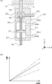
- FIG. 8A shows a schematic configuration of the adjusting valve 60 when the slurry 3 is discharged from the die 10.
- the configuration of the adjusting valve 60 is similar to that shown in FIGS. 6A and 6B, and when the valve 66 is separated from the opening of the cavity 63, the adjustment valve 60 is separated from the die 10 via the pipe 50.
- the slurry 3 flows in, and the amount of the slurry 3 discharged from the discharge port 18 of the die 10 decreases accordingly.
- the opening degree of the valve 66 of the adjusting valve 60 in this manner, the amount of the slurry 3 discharged from the discharge port 18 of the die 10 can be adjusted.
- the opening degree of the valves 66 of the plurality of adjustment valves 60 arranged in the width direction of the die 10 is individually adjusted to adjust the width direction distribution of the amount of the slurry 3 discharged from the discharge port 18 of the die 10. be able to.
- the opening degree sensor 70 is detached from the manufacturing apparatus 1 as shown in FIG. 8(A). Therefore, it is possible to prevent the explosion from occurring.
- FIG. 8B is a graph showing a calibration curve of the opening degree of the valve 66 and the flow rate of the slurry 3 flowing through the adjustment valve 60.
- the straight line, the one-dot chain line, and the two-dot chain line in the graph of FIG. 8B show the calibration curves for three different types of slurry 3. Even if the opening degree of the valve 66 is the same, if the viscosity of the slurry 3 is different, the flow rate of the slurry 3 flowing through the adjusting valve 60 is different. Therefore, this calibration curve is basically acquired every time the slurry 3 is replaced. Therefore, the frequency of acquiring the calibration curve of the opening degree of the valve 66 and the flow rate of the slurry 3 flowing through the adjustment valve 60 is more than the frequency of acquiring the calibration curve of the supply pressure to the adjustment valve 60 and the opening degree of the valve 66. Is high.
- the adjustment valve 60 can be supplied to the adjustment valve 60 without measuring the position of the moving portion 62 at the time of discharging the slurry 3. If only the supply pressure value can be measured, the opening degree of the valve 66 can be estimated. Therefore, as shown in FIG. 8A, it is possible to perform the operation without the opening sensor 70, that is, with the opening sensor 70 removed from the manufacturing apparatus 1. Therefore, it is possible to prevent the explosion due to the operation of the adjusting valve 60.
- the calibration curve between the supply pressure to the regulating valve 60 and the opening degree of the valve 66 shown in FIG. 7 and the opening degree of the valve 66 and the flow rate of the slurry 3 in the regulating valve 60 shown in FIG. The two types of calibration curves are combined to adjust the amount of the slurry 3 discharged from the die 10. Accordingly, the calibration curve of the opening degree of the valve 66 and the flow rate of the slurry 3 flowing through the adjustment valve 60, which are frequently acquired, is acquired by only one adjustment valve 60, and the obtained calibration curve is sent to the adjustment valve 60 in each adjustment valve 60. Since it can be combined with the calibration curve of the supply pressure and the opening degree of the valve 66, it is possible to reduce the labor required to acquire the calibration curve when the number of the adjusting valves 60 is relatively large.
- the manufacturing method of the battery electrode plate by the manufacturing apparatus 1 having the above configuration is as follows.
- the valve 66 is opened by the value of the internal pressure of the adjusting valve 60 and the measured value of the opening sensor 70.
- the frequency of obtaining the calibration curve may be the frequency for each periodic maintenance of the manufacturing apparatus 1.
- the slurry 3 is discharged from the discharge port 18 of the die 10 and the opening degree of the valve 66 of each adjustment valve 60 by using the calibration curve. Is controlled to adjust the outflow amount or inflow amount of the slurry 3 from the adjusting valve 60.
- FIG. 9 is a diagram showing a schematic configuration of a modified example of the adjusting valve 60.
- a spring 69 is used instead of the fluid as a means for applying pressure to one of the spaces.
- the opening of the valve 66 is reduced by the reaction force of the spring 69, and the opening of the cavity 63 is closed.
- the spring 69 may be installed on the opposite side of the cavity 64.
- the manufacturing apparatus 1 of the present invention is not limited to the illustrated form, and may have other forms within the scope of the present invention.
- the inflow part 16 is connected to the bottom part 17 of the first manifold 11, and the slurry 3 is allowed to flow in from the bottom part 17, but the inflow part 16 is It may be configured to be connected to the side portion (the middle portion in the height direction) of the first manifold 11.
- the die 10 is installed so that the slurry 3 of the first manifold 11 flows from the discharge port 18 to the substrate 2 through the slit 12 in the horizontal direction.
- the installation posture of the die 10 may be other than this.
- the die 10 may be installed in a posture in which the first manifold 11 and the slit 12 are arranged side by side in the vertical direction.
- the slurry 3 of the first manifold 11 is discharged through the slit 12 through the discharge port.
- the die 10 may be installed so that the flow direction from 18 to the base material 2 is vertically upward.
- the adjusting portions 33 and 34 are provided at the two intermediate portions 12c and 12d between the both end portions 12a and 12b, but the number of adjusting portions provided at the intermediate portions is not limited. Other than this, the adjusting portion may be provided at least at one place in the middle between the both ends 12a and 12b.
- the opening sensor 70 can be attached to and detached from only one adjustment valve 60, and there is no opening sensor in the vicinity of the other adjustment valves 60. Is also good. Then, the calibration curve of the opening degree of the valve 66 obtained by the adjustment valve 60 having the opening degree sensor 70 may be reflected in another adjustment valve 60.
- the form of the adjusting valve 60 is a needle valve, but the form is not limited to this, and any other form can be adopted as long as the opening of the valve is adjusted by the change of the internal pressure due to the inflow and outflow of the fluid.
- a butterfly valve or a diaphragm valve may be used.
- the manufacturing apparatus 1 of the present invention is effective when the coating liquid to be applied is a slurry having a high viscosity, and is applied when manufacturing a product (for example, an optical film) by applying a slurry having a high viscosity. Good.
- the thickness of the coating layer formed on the base material 2 is made uniform in the width direction by making the amount of discharge from the discharge port 18 uniform in the width direction.
- the discharge amount of the discharge port 18 is not limited to be uniform in the width direction.
- FIG. 10(A) when the thickness of the coating layer formed on the base material 2 changes so that the thickness of the end portion decreases with the passage of time, the slurry at both ends of the slit 12 is adjusted by each adjusting portion. It is better to increase the flow rate of 3. As a result, as shown in FIG.
- the shape of the coating layer becomes thicker in the width direction immediately after ejection, but the thickness of the end portion decreases with the lapse of time, resulting in a thickness in the width direction. It is possible to obtain a coating film layer having a uniform thickness.
Landscapes
- Engineering & Computer Science (AREA)
- Chemical & Material Sciences (AREA)
- Manufacturing & Machinery (AREA)
- Chemical Kinetics & Catalysis (AREA)
- Electrochemistry (AREA)
- General Chemical & Material Sciences (AREA)
- Coating Apparatus (AREA)
- Life Sciences & Earth Sciences (AREA)
- Wood Science & Technology (AREA)
- Materials Engineering (AREA)
- Battery Electrode And Active Subsutance (AREA)
- Application Of Or Painting With Fluid Materials (AREA)
Abstract
L'invention concerne un appareil et un procédé pour produire une plaque d'électrode pour batterie avec laquelle il est possible de rendre uniforme l'épaisseur d'une couche de film revêtue formée sur un matériau de base sans provoquer d'explosion même lors de l'utilisation d'une suspension comprenant de grandes quantités d'un solvant organique. Plus précisément, l'appareil comprend : une filière (10) dans laquelle un premier collecteur (11), qui est formé à partir d'un espace qui est long dans la direction de la largeur et stocke une suspension (3), et un orifice d'évacuation (18), qui se raccorde au premier collecteur (11) par l'intermédiaire d'une fente (12) qui est large dans la direction de la largeur et évacue la suspension (3) sur un matériau de base (2), sont formés ; et un moyen d'alimentation (20) pour alimenter la suspension (3) au premier collecteur (11) à partir d'une partie d'entrée (16), qui est en communication avec le premier collecteur (11). La fente (12), entre le premier collecteur (11) et l'orifice d'évacuation (18), est disposée, dans la direction de la largeur, avec de multiples vannes de réglage (60) pour régler la quantité de suspension (3) évacuée à partir de l'orifice d'évacuation (18) en permettant à la suspension (3) de s'écouler à l'extérieur ou à l'intérieur. Dans les vannes de réglage (60), le degré d'ouverture d'une vanne (66) est réglé par des changements de pression interne résultant de la sortie/entrée d'un fluide, et en conséquence du réglage du degré d'ouverture de la vanne (66), la quantité d'écoulement à l'extérieur ou à l'intérieur de la suspension (3) à partir de la vanne de réglage (60) est réglée. De plus, un capteur de degré d'ouverture (70), qui mesure le degré d'ouverture de la vanne (66), est disposé sur les vannes de réglage (60) de manière amovible et le capteur de degré d'ouverture (70) est détaché de la vanne de réglage (60) lorsque la suspension (3) est évacuée de la filière (10).
Applications Claiming Priority (2)
| Application Number | Priority Date | Filing Date | Title |
|---|---|---|---|
| JP2019001614A JP7208798B2 (ja) | 2019-01-09 | 2019-01-09 | 電池用極板の製造装置および電池用極板の製造方法 |
| JP2019-001614 | 2019-01-09 |
Publications (1)
| Publication Number | Publication Date |
|---|---|
| WO2020145204A1 true WO2020145204A1 (fr) | 2020-07-16 |
Family
ID=71521311
Family Applications (1)
| Application Number | Title | Priority Date | Filing Date |
|---|---|---|---|
| PCT/JP2019/051460 Ceased WO2020145204A1 (fr) | 2019-01-09 | 2019-12-27 | Appareil et procédé de production de plaque d'électrode pour batterie |
Country Status (2)
| Country | Link |
|---|---|
| JP (1) | JP7208798B2 (fr) |
| WO (1) | WO2020145204A1 (fr) |
Cited By (3)
| Publication number | Priority date | Publication date | Assignee | Title |
|---|---|---|---|---|
| CN116871124A (zh) * | 2023-08-01 | 2023-10-13 | 苏州擎动动力科技有限公司 | 一种涂布模头以及涂布装置 |
| WO2024008857A1 (fr) * | 2022-07-06 | 2024-01-11 | Northvolt Ab | Système de revêtement d'une bouillie sur un substrat et procédé de revêtement utilisant ledit système |
| WO2024114103A1 (fr) * | 2022-11-29 | 2024-06-06 | 宁德时代新能源科技股份有限公司 | Matrice de revêtement et appareil de revêtement |
Families Citing this family (3)
| Publication number | Priority date | Publication date | Assignee | Title |
|---|---|---|---|---|
| JP7398347B2 (ja) * | 2020-09-01 | 2023-12-14 | 東レエンジニアリング株式会社 | 塗工装置 |
| JP2022063935A (ja) * | 2020-10-13 | 2022-04-25 | 正文 松永 | 塗布方法、燃料電池の製造方法または燃料電池、2次電池の製造方法または2次電池、全固体電池の製造方法または全固体電池 |
| JP7813988B2 (ja) * | 2020-11-11 | 2026-02-16 | パナソニックIpマネジメント株式会社 | 電極合剤スラリーの塗工装置 |
Citations (5)
| Publication number | Priority date | Publication date | Assignee | Title |
|---|---|---|---|---|
| JPH0361962U (fr) * | 1989-10-23 | 1991-06-18 | ||
| JP2014188426A (ja) * | 2013-03-27 | 2014-10-06 | Nec Corp | 間欠塗布装置および塗布方法 |
| JP2015062869A (ja) * | 2013-09-25 | 2015-04-09 | 日本電気株式会社 | 塗工装置及び塗工方法 |
| JP2015097198A (ja) * | 2013-10-11 | 2015-05-21 | 東レエンジニアリング株式会社 | 電池用極板の製造装置及びその製造方法 |
| JP2015153527A (ja) * | 2014-02-12 | 2015-08-24 | 東レエンジニアリング株式会社 | 電池用極板の製造装置 |
Family Cites Families (2)
| Publication number | Priority date | Publication date | Assignee | Title |
|---|---|---|---|---|
| KR101211776B1 (ko) * | 2006-03-09 | 2012-12-12 | 삼성에스디아이 주식회사 | 슬러리 공급 장치 및 그 장치를 가지는 슬러리 도포 장비 |
| JP2018037206A (ja) * | 2016-08-30 | 2018-03-08 | 東レエンジニアリング株式会社 | 電池用極板の製造装置及びその保守方法 |
-
2019
- 2019-01-09 JP JP2019001614A patent/JP7208798B2/ja active Active
- 2019-12-27 WO PCT/JP2019/051460 patent/WO2020145204A1/fr not_active Ceased
Patent Citations (5)
| Publication number | Priority date | Publication date | Assignee | Title |
|---|---|---|---|---|
| JPH0361962U (fr) * | 1989-10-23 | 1991-06-18 | ||
| JP2014188426A (ja) * | 2013-03-27 | 2014-10-06 | Nec Corp | 間欠塗布装置および塗布方法 |
| JP2015062869A (ja) * | 2013-09-25 | 2015-04-09 | 日本電気株式会社 | 塗工装置及び塗工方法 |
| JP2015097198A (ja) * | 2013-10-11 | 2015-05-21 | 東レエンジニアリング株式会社 | 電池用極板の製造装置及びその製造方法 |
| JP2015153527A (ja) * | 2014-02-12 | 2015-08-24 | 東レエンジニアリング株式会社 | 電池用極板の製造装置 |
Cited By (3)
| Publication number | Priority date | Publication date | Assignee | Title |
|---|---|---|---|---|
| WO2024008857A1 (fr) * | 2022-07-06 | 2024-01-11 | Northvolt Ab | Système de revêtement d'une bouillie sur un substrat et procédé de revêtement utilisant ledit système |
| WO2024114103A1 (fr) * | 2022-11-29 | 2024-06-06 | 宁德时代新能源科技股份有限公司 | Matrice de revêtement et appareil de revêtement |
| CN116871124A (zh) * | 2023-08-01 | 2023-10-13 | 苏州擎动动力科技有限公司 | 一种涂布模头以及涂布装置 |
Also Published As
| Publication number | Publication date |
|---|---|
| JP7208798B2 (ja) | 2023-01-19 |
| JP2020113382A (ja) | 2020-07-27 |
Similar Documents
| Publication | Publication Date | Title |
|---|---|---|
| JP7208798B2 (ja) | 電池用極板の製造装置および電池用極板の製造方法 | |
| JP6422711B2 (ja) | 電池用極板の製造装置及びその製造方法 | |
| JP6280383B2 (ja) | 電池用極板の製造装置 | |
| JP6215098B2 (ja) | 電池用極板の製造装置 | |
| KR102473483B1 (ko) | 전지용 극판의 제조 장치 | |
| KR101252957B1 (ko) | 코팅장치 및 이를 이용한 코팅 방법 | |
| US8753710B2 (en) | Coating method | |
| KR20150060704A (ko) | 도포 장치 및 도포 방법 | |
| JP2016033884A (ja) | 電池用極板の製造装置 | |
| JP2017079180A (ja) | 電池極板の製造装置及び電池極板の製造方法 | |
| JP6011007B2 (ja) | 塗工システム | |
| JP2017183010A (ja) | 電池用極板の製造装置 | |
| CN110997159B (zh) | 涂敷装置及涂敷方法 | |
| JP5023335B2 (ja) | ダイ、ダイ方式塗布装置及び塗布方法 | |
| KR101211776B1 (ko) | 슬러리 공급 장치 및 그 장치를 가지는 슬러리 도포 장비 | |
| JP7398347B2 (ja) | 塗工装置 | |
| JP2018037206A (ja) | 電池用極板の製造装置及びその保守方法 | |
| JP4974580B2 (ja) | ダイ方式塗布装置及び塗布方法 | |
| JP2020032361A (ja) | 塗工装置及び塗工方法 | |
| JP2020131145A (ja) | 塗工装置及び塗工方法 | |
| JP2016038936A (ja) | 電池用極板の製造装置 | |
| JP2017079179A (ja) | 電池極板の製造装置及び電池極板の製造方法 | |
| KR100566408B1 (ko) | 반도체 제조 공정에서의 도포막 두께 제어 장치 및 그의제어 방법 | |
| JP2016175003A (ja) | 塗布装置及び塗布方法 | |
| JP2023133667A (ja) | 塗布装置 |
Legal Events
| Date | Code | Title | Description |
|---|---|---|---|
| 121 | Ep: the epo has been informed by wipo that ep was designated in this application |
Ref document number: 19908107 Country of ref document: EP Kind code of ref document: A1 |
|
| NENP | Non-entry into the national phase |
Ref country code: DE |
|
| 122 | Ep: pct application non-entry in european phase |
Ref document number: 19908107 Country of ref document: EP Kind code of ref document: A1 |