WO2020145389A1 - 自動分析装置 - Google Patents
自動分析装置 Download PDFInfo
- Publication number
- WO2020145389A1 WO2020145389A1 PCT/JP2020/000687 JP2020000687W WO2020145389A1 WO 2020145389 A1 WO2020145389 A1 WO 2020145389A1 JP 2020000687 W JP2020000687 W JP 2020000687W WO 2020145389 A1 WO2020145389 A1 WO 2020145389A1
- Authority
- WO
- WIPO (PCT)
- Prior art keywords
- reagent container
- reagent
- stopper
- automatic analyzer
- container
- Prior art date
- Legal status (The legal status is an assumption and is not a legal conclusion. Google has not performed a legal analysis and makes no representation as to the accuracy of the status listed.)
- Ceased
Links
Images



Classifications
-
- G—PHYSICS
- G01—MEASURING; TESTING
- G01N—INVESTIGATING OR ANALYSING MATERIALS BY DETERMINING THEIR CHEMICAL OR PHYSICAL PROPERTIES
- G01N35/00—Automatic analysis not limited to methods or materials provided for in any single one of groups G01N1/00 - G01N33/00; Handling materials therefor
- G01N35/10—Devices for transferring samples or any liquids to, in, or from, the analysis apparatus, e.g. suction devices, injection devices
- G01N35/1002—Reagent dispensers
-
- G—PHYSICS
- G01—MEASURING; TESTING
- G01N—INVESTIGATING OR ANALYSING MATERIALS BY DETERMINING THEIR CHEMICAL OR PHYSICAL PROPERTIES
- G01N35/00—Automatic analysis not limited to methods or materials provided for in any single one of groups G01N1/00 - G01N33/00; Handling materials therefor
- G01N35/10—Devices for transferring samples or any liquids to, in, or from, the analysis apparatus, e.g. suction devices, injection devices
-
- G—PHYSICS
- G01—MEASURING; TESTING
- G01N—INVESTIGATING OR ANALYSING MATERIALS BY DETERMINING THEIR CHEMICAL OR PHYSICAL PROPERTIES
- G01N35/00—Automatic analysis not limited to methods or materials provided for in any single one of groups G01N1/00 - G01N33/00; Handling materials therefor
- G01N35/00584—Control arrangements for automatic analysers
- G01N35/00722—Communications; Identification
- G01N35/00732—Identification of carriers, materials or components in automatic analysers
-
- G—PHYSICS
- G01—MEASURING; TESTING
- G01N—INVESTIGATING OR ANALYSING MATERIALS BY DETERMINING THEIR CHEMICAL OR PHYSICAL PROPERTIES
- G01N35/00—Automatic analysis not limited to methods or materials provided for in any single one of groups G01N1/00 - G01N33/00; Handling materials therefor
- G01N35/10—Devices for transferring samples or any liquids to, in, or from, the analysis apparatus, e.g. suction devices, injection devices
- G01N35/1079—Devices for transferring samples or any liquids to, in, or from, the analysis apparatus, e.g. suction devices, injection devices with means for piercing stoppers or septums
-
- G—PHYSICS
- G01—MEASURING; TESTING
- G01N—INVESTIGATING OR ANALYSING MATERIALS BY DETERMINING THEIR CHEMICAL OR PHYSICAL PROPERTIES
- G01N35/00—Automatic analysis not limited to methods or materials provided for in any single one of groups G01N1/00 - G01N33/00; Handling materials therefor
- G01N35/10—Devices for transferring samples or any liquids to, in, or from, the analysis apparatus, e.g. suction devices, injection devices
- G01N35/1081—Devices for transferring samples or any liquids to, in, or from, the analysis apparatus, e.g. suction devices, injection devices characterised by the means for relatively moving the transfer device and the containers in an horizontal plane
- G01N35/1083—Devices for transferring samples or any liquids to, in, or from, the analysis apparatus, e.g. suction devices, injection devices characterised by the means for relatively moving the transfer device and the containers in an horizontal plane with one horizontal degree of freedom
-
- G—PHYSICS
- G01—MEASURING; TESTING
- G01N—INVESTIGATING OR ANALYSING MATERIALS BY DETERMINING THEIR CHEMICAL OR PHYSICAL PROPERTIES
- G01N35/00—Automatic analysis not limited to methods or materials provided for in any single one of groups G01N1/00 - G01N33/00; Handling materials therefor
- G01N35/00584—Control arrangements for automatic analysers
- G01N35/00722—Communications; Identification
- G01N35/00732—Identification of carriers, materials or components in automatic analysers
- G01N2035/00792—Type of components bearing the codes, other than sample carriers
- G01N2035/00811—Type of components bearing the codes, other than sample carriers consumable or exchangeable components other than sample carriers, e.g. detectors, flow cells
Definitions
- the present invention relates to an automatic analyzer that analyzes the concentration of a predetermined component in a biological sample (hereinafter referred to as a sample) such as blood or urine using a reagent.
- a biological sample hereinafter referred to as blood or urine
- Patent Document 1 discloses a container installation part in which a reagent container can be installed and an opening/closing provided in the reagent container installation part.
- reagents used in automatic analyzers There are two types of reagents used in automatic analyzers: reagents that are individually prepared for each measurement target item (hereinafter, assay reagents) and reagents commonly used for various measurement target items (hereinafter, system reagents). Often used reagents.
- a container installation part capable of installing a reagent container accommodating a reagent used for analysis and a cover for opening or closing the container installation part are installed, and a cover part is provided. It describes how to lock or unlock.
- the cover and the nozzle that is inserted into the reagent work together.
- the reagent type is recognized, and when it is recognized as the correct reagent type, the cover and the nozzle are allowed to descend, and when the reagent is not recognized as the correct reagent type, the nozzle descending is prohibited to prevent erroneous installation.
- the cover and the nozzle are prohibited from being raised except when the reagent should be replaced, thereby preventing the user from accidentally removing the reagent.
- the present invention has been made to solve the above problems, and provides an automatic analyzer that realizes prevention of misplacement of reagent species and prevention of reagent removal at the wrong timing with a smaller space and component parts.
- the present invention includes a plurality of means for solving the above problems.
- a reagent container setting section for setting a reagent container accommodating a reagent used for analysis, and the reagent are used.
- a joint portion for joining the supply channel connecting the reagent container installed in the reagent container installation portion to the reagent container, and a slot portion for introducing the reagent container into the joint portion.
- a stopper that prevents the installed reagent container from moving in the slot portion is inserted, and the stopper inserts the reagent container before joining the reagent container to the joining portion.
- FIG. 7 is a flowchart when a reagent container is installed in the automatic analyzer of the present invention. It is a figure which shows the positional relationship of the reagent container and stopper at the time of step S1, S2, S3A, and S3B in FIG. It is a figure which shows the positional relationship of a reagent container and a stopper at the time of step S4 in FIG. It is a figure which shows the positional relationship of the reagent container and stopper at the time of step S5, S6 in FIG. It is a figure which shows the positional relationship of the reagent container and stopper at the time of step S7 in FIG. It is a flowchart at the time of reagent container removal in the automatic analyzer of the present invention.
- FIG. 18 is a diagram showing a positional relationship between the reagent container and the stopper at step S11 in FIG. 17.
- FIG. 18 is a diagram showing a positional relationship between the reagent container and the stopper when all the steps in FIG.
- an immunoanalyzer will be described as an example.
- the automatic analyzer to which the configuration of the reagent container installation disclosed in the present invention is applied is not limited to the immunoanalyzer, and any automatic analyzer using a system reagent, for example, a biochemical automatic analyzer or a hematology test device, a liquid It can be applied to a chromatograph mass spectrometer and the like.
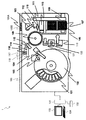
- FIG. 1 is a diagram showing the overall configuration of the automatic immune analyzer of the present embodiment.
- the automatic immunoassay device 1 shown in FIG. 1 is a device for reacting a sample with a reagent and measuring the reacted reaction solution, and includes a transport line 100, a sample dispensing mechanism 103, an incubator 109, a magazine 108, and a transport.
- Mechanism 113 Reagent Disk 102, Reagent Dispensing Mechanism 104, Magnetic Particle Stirring Mechanism 105, Magnetic Separation Unit 114, BF Separation Transfer Mechanism 115, Reaction Solution Suction Mechanism 116, Cleaning Solution A Discharging Mechanism 117, Cleaning Solution B Discharging Mechanism 118, Detection It is provided with a part transport mechanism 121, a detection solution ejection mechanism 119, a detection unit 120, a control unit 131, a recording device 132, a display device 133, and an input device 134.
- the transport line 100 is a line for transporting a rack 100A capable of mounting a plurality of sample containers 100B containing a sample to a sample dispensing position or the like.
- the sample dispensing mechanism 103 is a nozzle for sucking the sample contained in the sample container 100B and discharging the sample into the reaction container 106 on the incubator 109.
- the incubator 109 is a disk for carrying out the reaction between the sample and the reagent at a constant temperature, and the temperature of the incubator 109 is kept at a predetermined temperature by a heater (not shown) to accelerate the reaction between the sample and the reagent.
- a plurality of reaction vessels 106 are held in the incubator 109 and serve as a place where the sample and the reagent are mixed and reacted.
- the magazine 108 contains a disposable dispensing tip 107 used by being attached to the tip of the sample dispensing mechanism 103 when performing sample dispensing/dispensing, and a sample and a reagent dispensed by the sample dispensing mechanism 103 are put in and reacted.
- the reaction container 106 for carrying out is stored.
- the transport mechanism 113 transports the unused reaction container 106 held in the magazine 108 to the incubator 109, the used reaction container 106 to the reaction container discarding unit 110, and the unused reaction container 106 held in the magazine 108.
- the dispensing tip 107 is transported to the dispensing tip mounting position 111, and the used dispensing tip 107 is transported to the dispensing tip disposal place 112.
- the reagent disc 102 is a disc for storing the reagent container 101 containing the assay reagent, and is kept cold in order to suppress the deterioration of the assay reagent.
- the reagent dispensing mechanism 104 is a nozzle for sucking the reagent stored in the reagent container 101 in the reagent disk 102 and discharging it to the reaction container 106.
- the magnetic particle stirring mechanism 105 stirs the magnetic particle solution of the reagents in the reagent disk 102.
- the BF separation transfer mechanism 115 transfers the reaction container 106 in which the magnetic particle solution is dispensed from the incubator 109 to the magnetic separation unit 114.
- the magnetic separation unit 114 performs magnetic separation processing on the reaction container 106 in which the magnetic particle solution is dispensed.
- the reaction solution suction mechanism 116 sucks the reaction solution from the reaction container 106 conveyed to the magnetic separation unit 114.
- the cleaning liquid A ejection mechanism 117 ejects the cleaning liquid A into the reaction container 106 transported to the magnetic separation unit 114.
- the cleaning liquid B ejection mechanism 118 ejects the cleaning liquid B into the reaction container 106 conveyed to the magnetic separation unit 114.
- the detector transport mechanism 121 transports the reaction container 106 from the incubator 109 to the detector 120 or from the detector 120 to the incubator 109.
- the detection solution ejection mechanism 119 ejects a reagent for detection to the reaction container 106 conveyed to the detection unit 120 by the detection unit conveyance mechanism 121.
- the detection unit 120 detects the measurement target substance of the reaction liquid in the reaction container 106 in which the detection reagent is discharged by the detection solution discharge mechanism 119.
- the cleaning process executed in the magnetic separation unit 114 is performed to remove the substance derived from the sample remaining in the reaction solution.
- cleaning is performed using two kinds of cleaning liquids in sequence.
- An aqueous solution is used as the cleaning liquid A and mainly removes coexisting substances such as inorganic salts.
- a solution containing an organic solvent is used as the cleaning liquid B, and mainly removes coexisting substances such as lipids and proteins.
- the detection reagent ejected from the detection solution ejection mechanism 119 is used after the washing process to adjust the pH and the like so as to have a liquid property suitable for detection.
- the cleaning liquids A and B and the detection solution are collectively called a system reagent.
- the control unit 131 is a computer that controls various operations of the above-mentioned members and performs arithmetic processing to obtain the concentration of a predetermined component in the sample from the detection result performed by the detection unit 120. It is composed of a processor, a CPU, and the like. The control of the operation of each device by the control unit 131 is executed by various programs. This program is stored in the recording device 132 or the like and is read and executed by the CPU.
- control process of the operation executed by the control unit 131 may be integrated into one program, may be divided into a plurality of programs, or may be a combination thereof. Further, part or all of the program may be realized by dedicated hardware or may be modularized.
- the recording device 132 is a recording medium in which the data regarding the sample loaded in the automatic immune analyzer 1 and the analysis result are recorded, and is configured by a semiconductor memory such as a flash memory or a magnetic disk such as an HDD.
- the recording device 132 also records various computer programs and the like for controlling the operation of each device in the automatic immune analyzer 1 and executing various display processes described later.
- the display device 133 is a display device such as a liquid crystal display which displays the analysis result and information related to the progress of the analysis.
- the input device 134 is composed of a keyboard and a mouse for inputting data.
- the user inserts the rack 100A into the automatic analyzer with the sample such as blood or urine to be analyzed contained in the sample container 100B.
- the unused reaction container 106 and the dispensing tip 107 are transported to the incubator 109 and the dispensing tip mounting position 111 by the transport mechanism 113.
- the reagent dispensing mechanism 104 accesses the inside of the reagent disk 102, so that the reagent stored in the reagent container 101 is dispensed into the reaction container 106 on the incubator 109.
- the reaction referred to herein means, for example, the binding of the analyte and the luminescent labeling substance by the antigen-antibody reaction using the luminescent labeled antibody that reacts only with the specific antigen of the analyte as a reagent.
- the used dispensing tip 107 is transported to the dispensing tip discarding place 112 by the transport mechanism 113 and discarded.
- reaction container 106 placed in the incubator 109 for a predetermined time is transported to the magnetic separation unit 114 by the BF separation transport mechanism 115.
- the sample is magnetically separated, then the unnecessary solution is discharged from the reaction solution suction mechanism 116, and a system reagent called a cleaning liquid is discharged from the cleaning liquid A discharging mechanism 117 and the cleaning liquid B discharging mechanism 118. To be done.
- the BF separation transfer mechanism 115 transfers the reaction vessel 106 from the magnetic separation section 114 to the incubator 109 again.
- the reaction container 106 which has been in the incubator 109 for a predetermined time, is transported to the detection unit 120 by the detection unit transport mechanism 121, and the detection reagent is discharged by the detection solution discharge mechanism 119. After that, the detection unit 120 detects a signal from the reaction solution, and the detection result is output to the control unit 131.
- the control unit 131 obtains the concentration of the predetermined component in the sample, and the result is displayed on the display device 133 to notify the user and recorded in the recording device 132.
- reaction container 106 is transferred to the reaction container discarding unit 110 by the detection unit transfer mechanism 121 and the transfer mechanism 113, and is discarded.
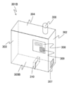
- FIG. 2 and FIG. 3 are diagrams showing an example of an outline of a reagent container that stores a system reagent used in the automatic immune analyzer.
- the reagent container 301A shown in FIG. 2 is a plastic container having a shape in which the depth is longer than the width.
- the respective surfaces shown in FIG. 2 will be described as the insertion direction front surface 302, side surface 303, top surface 304, and bottom surface 305A.
- a cylindrical screw lid 306 is provided on the upper surfaces 304 of the reagent containers 301A and 301B.
- the screw lid 306 is loosened by the user after installing the reagent container in the device and is used to introduce air through the gap.
- a septum portion 307 is provided on a front surface 302 of each of the reagent containers 301A and 301B at a position where a pierce needle 205 provided at a tip portion of a slot 201 of a system reagent installation portion 200 described later can be inserted.
- the septum portion 307 is made of rubber, and when the pierce needle 205 penetrates, the supply channel 206 provided at the tip of the pierce needle 205 communicates with the inside of the reagent containers 301A and 301B to supply the system reagent to the apparatus. Since the septum portion 307 is made of rubber, even if the pierce needle 205 penetrates, the sealing property can be secured and the system reagent does not leak out.
- a label 308 is attached to the side surface 303 of the reagent container 301A, which describes the type of reagent, the expiration date, and the like.
- An RFID tag 309 is attached to the label 308.
- the RFID tag 309 stores information about the system reagent such as reagent type, lot number, expiration date, whether it has been used, and the number of remaining uses.
- the reagent container 301B shown in FIG. 3 is provided with a cutout portion 310 on the bottom surface 305B.
- the function of the cutout portion 310 will be described later.
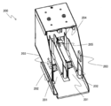
- FIG. 4 is a perspective view of the system reagent installation unit 200 in the automatic immune analyzer of the present embodiment.
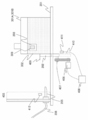
- FIG. 5 schematically shows one of the slots 201 installed two by two in the system reagent installation unit 200 described in FIG. Since the slots 201 have the same structure, only one of them will be described.
- system reagent installation units 200 as shown in FIG. 4 are installed at three places behind the front cover.
- the system reagent installation section 200 has two slots 201 into which reagent containers 301A and 301B containing system reagents used for analysis are inserted, and a total of six systems are provided in the system. Reagents can be installed.
- Each of the three types of system reagents has two installation locations. This is because when one reagent container becomes empty, the other reagent container is automatically used. This enables continuous operation without stopping the apparatus for installing the system reagent.
- the system reagent installation unit 200 includes a slot 201, a stopper 202, an RFID reader 203, a pierce needle 205, a motor 406, a belt 407, a stopper control unit 408, a stopper detection sensor 411, and a reagent container detection. It has a sensor 412.
- the slot 201 is a guide path for introducing reagent containers 301A and 301B described later into the piercing needle 205.
- the stopper 202 is installed on the guide path of the slot 201 at a position that prevents the installed reagent containers 301A and 301B from moving on the slot 201.
- the stopper 202 moves up and down by using the rotational force transmitted via the belt 407, so that the stopper 202 protrudes from the lower side of the slot 201 to the upper side or the upper side. It is configured to prevent the reagent containers 301A and 301B from being set or removed by retreating from the bottom to the bottom.
- the stopper 202 is arranged at a position where it comes into contact with the front surface 302 of the reagent containers 301A and 301B in the insertion direction before the reagent containers 301A and 301B are joined to the pierce needle 205 and prevents the installation. Furthermore, when the reagent containers 301A and 301B are joined to the pierce needle 205, even if the reagent containers 301A and 301B are to be removed, they interfere with the holding surfaces of the reagent containers 301A and 301B and prevent the slot 201 from moving. It is located in a position.
- the hold surface is a side surface 303 that is a surface facing the front surface 302 in the insertion direction of the reagent container 301A, and this surface is referred to as a reagent container rear end 509 (see FIG. 6 and the like) for convenience. Define.
- the reagent containers 301A and 301B interfere with the stopper 202, the reagent containers 301A and 301B are inserted into the slot tip portion 403 when the reagent containers 301A and 301B interfere with each other when the slot 201 is located above the slot 201 (the raised position 409 shown in FIG. 5). Interfere with.
- the stopper 202 when the stopper 202 is located below the slot 201 (the lowered position 410 shown in FIG. 5, the position shown by the alternate long and short dash line), the stopper 202 does not interfere with the front surface 302 of the reagent containers 301A and 301B in the insertion direction.
- the reagent containers 301A and 301B can be inserted into the slot tip portion 403.
- the stopper 202 holds the reagent container 301A, 301B. The surfaces interfere and you cannot pull them out.
- stopper control unit 408 fix the stopper 202 except when the reagent containers 301A and 301B are replaced, and drive-control the motor 406 so as to prevent the reagent containers 301A and 301B from moving.
- the stopper control unit 408 drives the stopper 202 to prevent the reagent containers 301A and 301B from being set when it is determined from the reagent information that the reagent containers 301A and 301B installed in the slot 201 are correct. It is desirable not to. When it is not determined that the reagent containers 301A and 301B are correct, it is desirable to prevent the stopper 202 from being driven and prevent the reagent containers 301A and 301B from being set.
- the stopper 202 By such operation of the stopper 202, it is desirable to control whether or not the reagent containers 301A and 301B can be inserted into the slot tip 403 and to control whether or not the reagent containers 301A and 301B can be pulled out from the slot tip 403.
- the stopper detection sensor 411 is installed in the lowered position of the stopper 202, and can determine whether the stopper 202 is in the raised position 409 or the lowered position 410.
- the reagent container detection sensor 412 is installed on the slot tip portion 403, and it is used to determine whether or not the reagent containers 301A and 301B have reached (installed) the slot tip portion 403.
- the RFID reader 203 is a device that reads the reagent information recorded on the RFID tag 309 attached to the label 308 of the reagent containers 301A and 301B, and is a front surface of the side surface of the slot 201 in the insertion direction of the reagent containers 301A and 301B.
- the RFID tag 309 is installed at a position where the RFID tag 309 can be read when the stopper 302 is stopped by hitting the stopper 202.
- the pierce needle 205 is a device for joining the supply channel 206 connecting the place where the reagent is used and the reagent containers 301A and 301B installed in the system reagent installation unit 200 to the reagent containers 301A and 301B, and is a slot. It is installed at the tip portion 204 of 201.
- the pierce needle 205 is connected to a liquid flow-driving device such as a supply channel 206 and a syringe (not shown), and can supply a reagent from the reagent containers 301A and 301B to a place of use on the device.
- a liquid flow-driving device such as a supply channel 206 and a syringe (not shown), and can supply a reagent from the reagent containers 301A and 301B to a place of use on the device.
- the stopper 202 is preferably installed in order to control whether the reagent containers 301A and 301B can be inserted into the pierce needle 205 by the stopper 202 and whether the reagent containers 301A and 301B can be pulled out from the pierce needle 205.
- the position condition will be described with reference to FIGS. 5 to 11.
- FIG. 5 is a diagram schematically showing the positional relationship between the reagent containers 301A and 301B in the slot 201, the stopper 202, and the pierce needle 205.
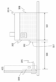
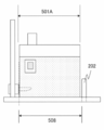
- 6 to 8 are diagrams for explaining the installation position of the stopper when the reagent container containing the system reagent shown in FIG. 2 is used.
- the insertion direction front surface 302 is inserted up to the abutting surface 504.
- the pierce needle 205 is sufficiently inserted into the reagent container 301A.
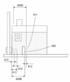
- the length of the reagent container 301A in the direction along the slot 201 is length 501, and the distance 508 from the pierce needle 205 (abutting surface 504) to the surface of the stopper 202 on the reagent container rear end 509 side is L2.
- the distance 510 from the reagent container rear end 509 to the surface of the stopper 202 on the reagent container rear end 509 side when the reagent container 301A is in contact with the pierce needle 205 is L3.
- the length from the abutting surface 504 of the reagent container 301A to the tip of the piercing needle 205 is a length 511
- the length obtained by removing the length 512 of the cut needle portion of the piercing needle 205 from the length 511 is a length 513.
- This length 513 is the minimum length required for the reagent container 301A to be kept bonded to the pierce needle 205, and the length 513 is L4. At this time, the relationship of L3 ⁇ L4 must be satisfied.
- condition (2) is that the connection between the reagent container 301A and the pierce needle 205 is not established even when the user mistakenly attempts to pull out the reagent container 301A in use while using the reagent container 301A. It is a condition that must be met to prevent loss and loss of system reagent to the device.
- the length 511 of the piercing needle 205 can be freely designed within a range satisfying the above condition (2).
- the length 511 of the piercing needle 205 be set to the minimum length within the range where the above condition is satisfied.
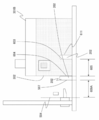
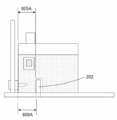
- FIGS. 9 to 11 are views for explaining the installation position of the stopper when the reagent container shown in FIG. 3 is used.
- the distance between the front surface 603 of the cutout portion 310 and the stopper rear end 604 is a distance 605.
- the distance from the abutting surface 504 to the stopper front surface 507 is a distance 609A.
- the maximum length 605A considering the manufacturing tolerance of the reagent container 301B is L5.
- the distance 609A from the pierce needle 205 to the surface of the stopper 202 on the rear end 611 side of the notch is L6, the relationship of L5 ⁇ L6 is satisfied.
- the manufacturing tolerance of the reagent container 301B is taken into consideration in the length from the pierce needle 205 of the reagent container 301B to the surface of the notch 310 on the rear end 611 side of the notch 310.
- the minimum length 605B is L7 and the distance 609B from the pierce needle 205 to the surface of the stopper 202 opposite to the rear end 611 side of the notch is L8, the relationship of L7>L8 must be satisfied.
- the length 612 from the surface of the cutout portion 310 on the cutout portion rear end 611 side to the surface of the stopper 202 facing the cutout portion rear end 611 side is L11.
- the distance from the abutting surface 504 to the tip of the piercing needle 205 is a length 613
- the length excluding the length 614 of the cut needle portion of the piercing needle 205 from the length 613 is a length 615.
- This length 615 is the minimum length necessary for the reagent container 301B to be kept bonded to the pierce needle 205, and when this length 615 is L12, it must satisfy the relationship of L12>L11.
- the length of the piercing needle 205 in FIG. 9 and the like is preferably set to the minimum length within the range satisfying the above-described conditions, as in the case of FIGS. 6 to 8.
- the notch portion 310 is not limited to being provided on the bottom surface of the reagent container 301B, but can be provided on the side surface 303 facing the front surface 302 in the insertion direction. In this case, among the conditions (3) to (6), the conditions (4) and (5) are unnecessary. In this case, the effect that the length of the slot 201 can be shortened is small, but the shape is simple.
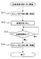
- FIG. 12 is a flowchart when installing the reagent container.
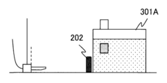
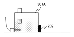
- 13 is a diagram showing the positional relationship between the reagent container 301B and the stopper 202 at steps S1, S2, S3A, and S3B in FIG. 12, and
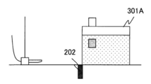
- FIG. 14 is the positional relationship between the reagent container 301B and the stopper 202 at step S4 in FIG.
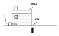
- FIG. 15 is a diagram showing the positional relationship between the reagent container 301B and the stopper 202 at steps S5 and S6 in FIG. 12, and
- FIG. 16 is a positional relationship between the reagent container 301B and the stopper 202 at step S7 in FIG.
- FIG. 13 is a diagram showing the positional relationship between the reagent container 301B and the stopper 202 at steps S1, S2, S3A, and S3B in FIG. 12
- FIG. 14 is the positional relationship between the reagent container 301B and the stopper 202 at step S4 in FIG.
- FIG. 15 is
- the user places the reagent container 301A to be installed in the slot 201.
- the stopper control unit 408 fixes the stopper 202 in the raised position.
- the tip of the reagent container 301A hits the stopper 202, and even if the reagent container 301A is inserted into the slot 201, the stopper 202 interferes and the further insertion is prevented (step S1 in FIG. 12).
- the stopper control unit 408 determines, based on the information from the reagent container detection sensor 412, whether or not the slot 201 in which the user intends to install the reagent container 301A is empty (step S2). If it is determined that the slot 201 is empty, the process proceeds to step S3A. On the other hand, when it is determined that the reagent container 301A is not empty, the reagent container 301A already in use is present, and the user cannot install the reagent container 301A. At this time, the process proceeds to step S8.
- the RFID reader 203 tries to read the RFID tag 309 at regular intervals (step S3A).
- the RFID reader 203 can read the information of the RFID tag 309.
- the stopper control unit 408 determines whether or not the reagent container 301A that the user intends to install is to be installed. Yes (step S3B).
- the stopper control unit 408 advances the process to step S8.
- the stopper control unit 408 issues an alarm (step S8) and notifies the user.
- the notification method includes, for example, turning on an indicator lamp and displaying an alarm on a user interface.
- the indicator lamp is composed of a button having a built-in LED, which is often arranged on the upper portion of the slot 201 in the system reagent installation unit 200. Depending on how the indicator lamp is turned on, it is often used to notify the user of the slot in which the reagent container that needs to be replaced is placed or to notify the user that an inappropriate reagent has been placed. .. Further, this indicator lamp also serves as a button as described above, and when the user presses the reagent container 301A when it is completely installed in the slot 201, the device side indicates that the installation of the reagent container 301A has been completed. It is recognizable.
- the stopper control unit 408 fixes the stopper 202 in the raised position (step S9), and ends the process. For this reason, the reagent container 301A interferes with the stopper 202, and the pushing of the reagent container 301A into the connection position remains blocked. This can prevent the user from installing the reagent container 301A, which should not be installed originally.
- the user confirms whether or not the reagent container 301A to be installed can be installed before the reagent container 301A is installed at the connection position.
- the pierce needle 205 When the reagent container 301A is installed at the connection position, the pierce needle 205 has already penetrated the septum portion 307 of the reagent container 301A and is in contact with the reagent in the container. Therefore, even if the user notices that the reagent container 301A has been mistaken by the notification from the device, mixing of the reagent occurs through the pierce needle 205 and the supply flow path 206 at the tip thereof. Since mixing with a reagent that should not be installed may affect the analysis performance, a complicated additional operation such as cleaning of the pierce needle 205 and the supply channel 206 is required before replacement with a correct reagent.
- the stopper control unit 408 also generate an alarm in this case.
- step S3B If it is determined in step S3B that the reagent container 301A that the user is trying to install may be installed, the stopper control unit 408 moves the stopper 202 to the lowered position and fixes it as shown in FIG. 14 (step S4).
- step S5 When the stopper 202 is fixed in the lowered position, the user can manually push the reagent container 301A to insert it into the slot 201 as shown in FIG. 15 (step S5). The user can easily recognize that the reagent container 301A may be installed since the stopper 202 is lowered.
- the stopper control unit 408 determines whether or not the reagent container 301A is at the connection position with the pierce needle 205 based on the information from the reagent container detection sensor 412 (step S6). As shown in FIG. 15, when the reagent container 301A is pushed to the connection position, the pierce needle 205 penetrates the septum portion 307 of the reagent container 301A to connect the device and the reagent, and the device is ready for use in the device.
- step S7 If it is determined that the reagent container 301A is present, the process proceeds to step S7. If not, the process returns to step S6 and waits for the reagent container 301A to be installed.
- step S6 If the reagent container 301A is not connected to the connection position within the predetermined time in step S6, there is a possibility that the installation of the reagent container 301A has been forgotten, and therefore the stopper control unit 408 notifies the alarm Is desirable.
- the stopper control unit 408 moves the stopper 202 to the raised position and fixes it as shown in FIG. 16 (step S7).
- the stopper control unit 408 moves the stopper 202 to the raised position and fixes it as shown in FIG. 16 (step S7).
- FIG. 17 is a flowchart when the reagent container 301A is removed
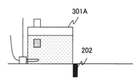
- FIG. 18 is a diagram showing the positional relationship between the reagent container 301A and the stopper 202 at step S11 in FIG. 17,
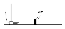
- FIG. 19 is a reagent when all the steps of FIG. 17 are completed. It is a figure which shows the positional relationship between the container 301A and the stopper 202.
- the control unit 131 When the reagent container 301A needs to be replaced, when the reagent container 301A is empty, when the reagent has expired, when the user explicitly instructs the device to replace the reagent, the device When it is determined that the installed reagent cannot be used based on the quality control result, etc. These determinations are made by the control unit 131.
- the stopper control unit 408 When it is determined that the replacement is necessary, the stopper control unit 408 notifies the user of the reagent replacement by blinking the indicator lamp or the like, and moves the stopper 202 to the lowered position to fix the reagent as shown in FIG. Yes (step S11).
- the user can pull out the reagent container 301A (step S12).
- the user can easily recognize whether or not the reagent container 301A can be removed by checking whether or not the stopper 202 is lowered.
- the stopper control unit 408 determines, based on the information from the reagent container detection sensor 412, the reagent container detection sensor 412 whether or not the reagent container 301A has been disconnected from the connection position (step S13).
- step S14 If it is determined that the reagent container 301A has been removed, the process proceeds to step S14. If not, the process returns to step S13 to wait for the reagent container 301A to be removed.
- the stopper control unit 408 preferably issues an alarm.
- the stopper control unit 408 moves the stopper 202 to the raised position and fixes it (step S14). This state is the state shown in FIG.
- the automatic immune analyzer 1 of the present embodiment described above is provided with a system reagent installation unit 200 in which reagent containers 301A and 301B containing reagents used in analysis are installed, a place where the reagent is used, and a system reagent installation unit 200. And a pierce needle 205 for joining the supply channel 206 connecting the reagent containers 301A, 301B installed in the reagent container 301A, 301B, and a slot 201 for introducing the reagent container 301A, 301B into the pierce needle 205. A stopper 202 that prevents the installed reagent containers 301A and 301B from moving in the slot 201 is provided.
- the stopper 202 contacts the front surface 302 of the reagent containers 301A and 301B in the insertion direction before joining the reagent containers 301A and 301B to the pierce needle 205 and prevents the installation, and the reagent containers 301A and 301B are joined to the pierce needle 205. In this state, even if the reagent containers 301A and 301B are to be removed, they are arranged at positions where they interfere with the hold surfaces of the reagent containers 301A and 301B and prevent the slot 201 from moving.
- the stopper 202 it is possible to achieve the two purposes by the operation of the stopper 202, that is, the reagent containers 301A and 301B are incorrectly installed, and the reagent containers 301A and 301B are accidentally removed during use of the reagent.
- the mechanism for achieving the above two purposes is only the stopper 202 and the devices related thereto, it is possible to downsize the system reagent installation unit 200.
- the system reagent installation unit 200 can be installed on the back side of the front cover that has more space than other locations.
- the number of mechanisms to be installed tends to increase.
- an increase in the size of the device imposes a limited space for installing the device, which is disadvantageous to the user.
- the reagent container 301A is manufactured from the length from the insertion direction front surface 302 of the reagent container 301A to the reagent container rear end 509.
- the maximum length 501A considering the above tolerance is L1 and the distance 508 from the pierce needle 205 to the surface of the stopper 202 on the reagent container rear end 509 side is L2, the relation of L1 ⁇ L2 is satisfied. The effect of preventing the removal of the reagent container 301A by 202 can be surely exhibited.
- the distance 510 from the reagent container rear end 509 to the surface of the stopper 202 on the reagent container rear end 509 side is L3, and the reagent container 301A is joined to the pierce needle 205.
- the minimum length 513 required to be maintained is L4, by satisfying the relationship of L3 ⁇ L4, it is possible to reliably prevent the pierce needle 205 from accidentally falling off from the reagent container 301A during use of the reagent. Therefore, stable analysis operation can be realized.
- the reagent container 301B has a cutout portion 310 on at least one of the bottom surface or the surface facing the insertion direction front surface 302, and the hold surface is the cutout portion rear end 611 of the cutout portion 310
- the maximum length 605A considering the manufacturing tolerance of the reagent container 301B is L5
- the notch portion of the pierce needle 205 to the stopper 202 is
- the distance 609A to the surface on the rear end 611 side is L6, the relationship of L5 ⁇ L6 is satisfied, and when the reagent container 301B has the cutout portion 310 on the bottom surface, the piercing of the reagent container 301B is performed.
- a minimum length 605B considering the manufacturing tolerance of the reagent container 301B is set to L7, and the pierce needle 205 is cut from the stopper 202.
- the distance 609B to the surface on the side opposite to the rear end 611 side of the notch is L8, the relationship of L7>L8 is satisfied, the width of the notch 310 is L9, and the width of the stopper 202 is L10.
- the relationship of L9>L10 it is possible to reliably exhibit the effect of preventing the reagent container 301B from being removed by the stopper 202.
- a distance 612 from the surface of the notch portion 310 on the notch portion rear end 611 side to the surface of the stopper 202 opposite to the notch portion rear end 611 side is L11, and the reagent container 301B is joined to the pierce needle 205.
- the minimum length 615 required to be maintained is L12, by satisfying the relationship of L12>L11, it is possible to reliably prevent the pierce needle 205 from accidentally falling off from the reagent container 301B during use of the reagent. Therefore, stable analysis operation can be realized.
- a stopper control unit 408 that drives and controls the stopper 202 is further provided, and the stopper control unit 408 fixes the stopper 202 except when the reagent containers 301A and 301B are replaced, and prevents the reagent containers 301A and 301B from moving. Therefore, it is possible to reliably prevent the wrong reagent containers 301A and 301B from being installed, and more stable sample analysis becomes possible.
- an RFID reader 203 for reading the reagent information recorded in the RFID tag 309 attached to the reagent containers 301A and 301B is further provided, and the stopper control unit 408
- the stopper 202 is not driven to prevent the reagent containers 301A and 301B from being set, and the reagent containers 301A and 301B are not determined to be correct.
- the stopper 202 is not driven and the setting of the reagent containers 301A and 301B is prevented. It is possible to make a judgment and notify the user, and it is possible to further reduce the burden on the user.
- the stopper 202 protrudes from the lower side of the slot 201 to the upper side to prevent the reagent containers 301A and 301B from being set or removed, so that the stopper 202 and the stopper 202 are provided below the system reagent installation unit 200 having a sufficient space.
- a motor 406 or the like for driving the stopper 202 can be arranged, and the increase in size of the device can be prevented more reliably.
- the stopper 202 may be mechanically projected from the transport surface of the slot 201 when the reagent containers 301A and 301B collide with the abutting surface. You can
- Reagent container detection sensor 501 Reagent container length 501A... Maximum length (L1) in consideration of manufacturing tolerance of reagent container 504... Reagent container abutting surface 507... Stopper front surface 508... Distance from reagent container abutting surface to stopper front surface (L2) 509... Rear end of reagent container (holding surface) 510: Distance between the rear end of the reagent container and the front surface of the stopper (L3) 511...Pierce needle length 512...Pierce needle needle-shaped portion length 513...Pierce needle total length minus needle-shaped portion length (L4) Reference numeral 603... Front surface of cutout portion 604... Rear end of stopper 605...
Landscapes
- Physics & Mathematics (AREA)
- Health & Medical Sciences (AREA)
- Life Sciences & Earth Sciences (AREA)
- Chemical & Material Sciences (AREA)
- Analytical Chemistry (AREA)
- Biochemistry (AREA)
- General Health & Medical Sciences (AREA)
- General Physics & Mathematics (AREA)
- Immunology (AREA)
- Pathology (AREA)
- Automatic Analysis And Handling Materials Therefor (AREA)
Priority Applications (4)
| Application Number | Priority Date | Filing Date | Title |
|---|---|---|---|
| JP2020565227A JPWO2020145389A1 (ja) | 2019-01-11 | 2020-01-10 | 自動分析装置 |
| EP20738909.9A EP3910343A4 (de) | 2019-01-11 | 2020-01-10 | Automatisierter analysator |
| US17/419,773 US20220065886A1 (en) | 2019-01-11 | 2020-01-10 | Automatic Analyzer |
| CN202080007554.8A CN113272652A (zh) | 2019-01-11 | 2020-01-10 | 自动分析装置 |
Applications Claiming Priority (2)
| Application Number | Priority Date | Filing Date | Title |
|---|---|---|---|
| JP2019-003570 | 2019-01-11 | ||
| JP2019003570 | 2019-01-11 |
Publications (1)
| Publication Number | Publication Date |
|---|---|
| WO2020145389A1 true WO2020145389A1 (ja) | 2020-07-16 |
Family
ID=71520364
Family Applications (1)
| Application Number | Title | Priority Date | Filing Date |
|---|---|---|---|
| PCT/JP2020/000687 Ceased WO2020145389A1 (ja) | 2019-01-11 | 2020-01-10 | 自動分析装置 |
Country Status (5)
| Country | Link |
|---|---|
| US (1) | US20220065886A1 (de) |
| EP (1) | EP3910343A4 (de) |
| JP (1) | JPWO2020145389A1 (de) |
| CN (1) | CN113272652A (de) |
| WO (1) | WO2020145389A1 (de) |
Cited By (1)
| Publication number | Priority date | Publication date | Assignee | Title |
|---|---|---|---|---|
| WO2021220571A1 (ja) * | 2020-04-27 | 2021-11-04 | 株式会社日立ハイテク | 自動分析装置 |
Families Citing this family (2)
| Publication number | Priority date | Publication date | Assignee | Title |
|---|---|---|---|---|
| EP4224165A4 (de) * | 2020-09-29 | 2024-10-23 | Hitachi High-Tech Corporation | Automatischer analysator |
| CN118618727A (zh) * | 2024-01-30 | 2024-09-10 | 中元汇吉生物技术股份有限公司 | 试剂容器存储装置、试剂交互模组、样本分析仪及系统 |
Citations (6)
| Publication number | Priority date | Publication date | Assignee | Title |
|---|---|---|---|---|
| JPH02128848A (ja) * | 1988-11-09 | 1990-05-17 | Canon Inc | インクジェット記録装置 |
| JPH05162335A (ja) * | 1991-12-11 | 1993-06-29 | Ricoh Co Ltd | 記録装置及びカートリッジ |
| JP2003246079A (ja) * | 2002-02-25 | 2003-09-02 | Konica Corp | インクジェット記録装置 |
| JP2010105268A (ja) * | 2008-10-30 | 2010-05-13 | Brother Ind Ltd | 液体供給装置及び液体容器 |
| JP2013039732A (ja) * | 2011-08-17 | 2013-02-28 | Seiko Epson Corp | 液体収容容器の誤挿入防止装置、液体収容容器、液体消費装置、および液体収容容器の誤挿入防止方法 |
| JP2016540221A (ja) * | 2013-12-13 | 2016-12-22 | エフ・ホフマン・ラ・ロッシュ・アー・ゲーF. Hoffmann La Roche Ag | 分析機器の試薬容器ホルダ、分析機器の試薬供給システム、及び分析機器 |
Family Cites Families (2)
| Publication number | Priority date | Publication date | Assignee | Title |
|---|---|---|---|---|
| DE3938559A1 (de) * | 1989-11-21 | 1991-05-23 | Boehringer Mannheim Gmbh | Reagenzbevorratungssystem fuer ein medizinisches analysegeraet |
| CN107554079B (zh) * | 2016-06-30 | 2019-06-07 | 珠海纳思达企业管理有限公司 | 一种打印机以及打印机用耗材容器插入方法 |
-
2020
- 2020-01-10 US US17/419,773 patent/US20220065886A1/en not_active Abandoned
- 2020-01-10 JP JP2020565227A patent/JPWO2020145389A1/ja active Pending
- 2020-01-10 WO PCT/JP2020/000687 patent/WO2020145389A1/ja not_active Ceased
- 2020-01-10 EP EP20738909.9A patent/EP3910343A4/de not_active Withdrawn
- 2020-01-10 CN CN202080007554.8A patent/CN113272652A/zh not_active Withdrawn
Patent Citations (6)
| Publication number | Priority date | Publication date | Assignee | Title |
|---|---|---|---|---|
| JPH02128848A (ja) * | 1988-11-09 | 1990-05-17 | Canon Inc | インクジェット記録装置 |
| JPH05162335A (ja) * | 1991-12-11 | 1993-06-29 | Ricoh Co Ltd | 記録装置及びカートリッジ |
| JP2003246079A (ja) * | 2002-02-25 | 2003-09-02 | Konica Corp | インクジェット記録装置 |
| JP2010105268A (ja) * | 2008-10-30 | 2010-05-13 | Brother Ind Ltd | 液体供給装置及び液体容器 |
| JP2013039732A (ja) * | 2011-08-17 | 2013-02-28 | Seiko Epson Corp | 液体収容容器の誤挿入防止装置、液体収容容器、液体消費装置、および液体収容容器の誤挿入防止方法 |
| JP2016540221A (ja) * | 2013-12-13 | 2016-12-22 | エフ・ホフマン・ラ・ロッシュ・アー・ゲーF. Hoffmann La Roche Ag | 分析機器の試薬容器ホルダ、分析機器の試薬供給システム、及び分析機器 |
Non-Patent Citations (1)
| Title |
|---|
| See also references of EP3910343A4 * |
Cited By (1)
| Publication number | Priority date | Publication date | Assignee | Title |
|---|---|---|---|---|
| WO2021220571A1 (ja) * | 2020-04-27 | 2021-11-04 | 株式会社日立ハイテク | 自動分析装置 |
Also Published As
| Publication number | Publication date |
|---|---|
| EP3910343A1 (de) | 2021-11-17 |
| EP3910343A4 (de) | 2022-10-05 |
| JPWO2020145389A1 (ja) | 2021-11-25 |
| CN113272652A (zh) | 2021-08-17 |
| US20220065886A1 (en) | 2022-03-03 |
Similar Documents
| Publication | Publication Date | Title |
|---|---|---|
| CN110873807B (zh) | 样本架 | |
| JP3553540B2 (ja) | 自動化学分析方法および装置 | |
| US10082517B2 (en) | Reagent management system | |
| US9128072B2 (en) | Apparatus for automatically performing analyses | |
| JP6573524B2 (ja) | 検体ラック搬送装置及び自動分析システム | |
| US20250208157A1 (en) | Method of transporting rack and sample measurement system | |
| US20130078617A1 (en) | Sample analyzer and method for controlling sample analyzer | |
| JP2008534924A (ja) | リニアラックを使用する自動化化学的又は生物学的分析装置のためのカルーセルシステム | |
| EP3508858B1 (de) | Probenmessverfahren und probenmessvorrichtung | |
| WO2020145389A1 (ja) | 自動分析装置 | |
| JP7080391B2 (ja) | 自動分析装置 | |
| US20110290890A1 (en) | Sample analyzer and reagent information writing method | |
| US11953511B2 (en) | Sample measurement system and method of transporting racks | |
| WO2017110486A1 (ja) | 検体ラック搬送装置及び自動分析システム | |
| JP5839987B2 (ja) | 自動分析装置 | |
| EP3779465B1 (de) | Probenmesssystem und gestellförderverfahren | |
| JP7281600B2 (ja) | 自動分析装置 | |
| JP5258090B2 (ja) | 自動分析装置 | |
| CN111683753A (zh) | 用于次级试管的试管托盘、次级试管搬运模块、以及搬运自动化处理系统中的次级试管的方法 | |
| WO2025224851A1 (ja) | 検体架設装置および自動分析装置 | |
| HK1227095A1 (en) | Reagent management system |
Legal Events
| Date | Code | Title | Description |
|---|---|---|---|
| 121 | Ep: the epo has been informed by wipo that ep was designated in this application |
Ref document number: 20738909 Country of ref document: EP Kind code of ref document: A1 |
|
| ENP | Entry into the national phase |
Ref document number: 2020565227 Country of ref document: JP Kind code of ref document: A |
|
| NENP | Non-entry into the national phase |
Ref country code: DE |
|
| ENP | Entry into the national phase |
Ref document number: 2020738909 Country of ref document: EP Effective date: 20210811 |