WO2020149005A1 - Outil de nettoyage de connecteur optique - Google Patents
Outil de nettoyage de connecteur optique Download PDFInfo
- Publication number
- WO2020149005A1 WO2020149005A1 PCT/JP2019/045543 JP2019045543W WO2020149005A1 WO 2020149005 A1 WO2020149005 A1 WO 2020149005A1 JP 2019045543 W JP2019045543 W JP 2019045543W WO 2020149005 A1 WO2020149005 A1 WO 2020149005A1
- Authority
- WO
- WIPO (PCT)
- Prior art keywords
- cleaning
- optical connector
- atomizer
- liquid
- unit
- Prior art date
- Legal status (The legal status is an assumption and is not a legal conclusion. Google has not performed a legal analysis and makes no representation as to the accuracy of the status listed.)
- Ceased
Links
Images


Classifications
-
- G—PHYSICS
- G02—OPTICS
- G02B—OPTICAL ELEMENTS, SYSTEMS OR APPARATUS
- G02B6/00—Light guides; Structural details of arrangements comprising light guides and other optical elements, e.g. couplings
- G02B6/24—Coupling light guides
- G02B6/36—Mechanical coupling means
- G02B6/38—Mechanical coupling means having fibre to fibre mating means
- G02B6/3807—Dismountable connectors, i.e. comprising plugs
- G02B6/3833—Details of mounting fibres in ferrules; Assembly methods; Manufacture
- G02B6/3866—Devices, tools or methods for cleaning connectors
-
- B—PERFORMING OPERATIONS; TRANSPORTING
- B05—SPRAYING OR ATOMISING IN GENERAL; APPLYING FLUENT MATERIALS TO SURFACES, IN GENERAL
- B05B—SPRAYING APPARATUS; ATOMISING APPARATUS; NOZZLES
- B05B17/00—Apparatus for spraying or atomising liquids or other fluent materials, not covered by the preceding groups
- B05B17/04—Apparatus for spraying or atomising liquids or other fluent materials, not covered by the preceding groups operating with special methods
- B05B17/06—Apparatus for spraying or atomising liquids or other fluent materials, not covered by the preceding groups operating with special methods using ultrasonic or other kinds of vibrations
- B05B17/0607—Apparatus for spraying or atomising liquids or other fluent materials, not covered by the preceding groups operating with special methods using ultrasonic or other kinds of vibrations generated by electrical means, e.g. piezoelectric transducers
- B05B17/0615—Apparatus for spraying or atomising liquids or other fluent materials, not covered by the preceding groups operating with special methods using ultrasonic or other kinds of vibrations generated by electrical means, e.g. piezoelectric transducers spray being produced at the free surface of the liquid or other fluent material in a container and subjected to the vibrations
-
- B—PERFORMING OPERATIONS; TRANSPORTING
- B05—SPRAYING OR ATOMISING IN GENERAL; APPLYING FLUENT MATERIALS TO SURFACES, IN GENERAL
- B05B—SPRAYING APPARATUS; ATOMISING APPARATUS; NOZZLES
- B05B17/00—Apparatus for spraying or atomising liquids or other fluent materials, not covered by the preceding groups
- B05B17/04—Apparatus for spraying or atomising liquids or other fluent materials, not covered by the preceding groups operating with special methods
- B05B17/06—Apparatus for spraying or atomising liquids or other fluent materials, not covered by the preceding groups operating with special methods using ultrasonic or other kinds of vibrations
- B05B17/0607—Apparatus for spraying or atomising liquids or other fluent materials, not covered by the preceding groups operating with special methods using ultrasonic or other kinds of vibrations generated by electrical means, e.g. piezoelectric transducers
- B05B17/0638—Apparatus for spraying or atomising liquids or other fluent materials, not covered by the preceding groups operating with special methods using ultrasonic or other kinds of vibrations generated by electrical means, e.g. piezoelectric transducers spray being produced by discharging the liquid or other fluent material through a plate comprising a plurality of orifices
- B05B17/0646—Vibrating plates, i.e. plates being directly subjected to the vibrations, e.g. having a piezoelectric transducer attached thereto
-
- B—PERFORMING OPERATIONS; TRANSPORTING
- B05—SPRAYING OR ATOMISING IN GENERAL; APPLYING FLUENT MATERIALS TO SURFACES, IN GENERAL
- B05B—SPRAYING APPARATUS; ATOMISING APPARATUS; NOZZLES
- B05B7/00—Spraying apparatus for discharge of liquids or other fluent materials from two or more sources, e.g. of liquid and air, of powder and gas
- B05B7/0012—Apparatus for achieving spraying before discharge from the apparatus
Definitions
- the present invention relates to an optical connector cleaning tool for cleaning a coupling end surface of an optical connector.
- optical coupling is realized for a fiber core having a diameter of only 10 ⁇ m with the coupling end faces of a ferrule fixed with optical fibers facing each other. ing. Therefore, if dirt such as oil and dust adheres to the coupling end surface of the optical connector, the insertion loss of the optical connector increases, the return loss decreases, and the optical signal cannot be transmitted normally. Therefore, it is important to clean the coupling end surface of the optical connector to remove dirt and deposits.
- Patent Document 2 As a cleaning tool for cleaning the above-mentioned coupling end surface of the optical connector, a cleaning tool for supplying the cleaning cloth from a reel around which the cleaning cloth is wound has been proposed (see Patent Document 2).
- JP 2006-204881 A JP, 2013-167875, A JP, 2017-217602, A
- the above-mentioned cleaning tool is a so-called dry type, and the cleaning power for dirt adhering to the coupling end surface of the optical connector was insufficient.
- a wet cleaning tool using a cleaning liquid is desired for cleaning this kind of adhered dirt.
- the cleaning liquid transported by pushing a piston pump is sprayed from a spray nozzle to supply the cleaning liquid to a cleaning unit such as a cleaning cloth.
- the cleaning liquid transported by pressing the piston pump is dripped from the liquid drop unit to supply the cleaning liquid to the cleaning unit.
- a cleaning tool has been proposed in which a cleaning liquid is supplied to a belt-shaped cleaning body by using a tube and the cleaning body is wetted with the cleaning liquid (see Patent Document 3).
- the cleaning liquid in the case of supplying the cleaning liquid as described above, it is not easy to control the amount of the cleaning liquid to be supplied, and the amount of cleaning liquid exceeding the required amount is supplied to the cleaning unit.
- the cleaning liquid that moistens the cleaning section may remain on the end surface of the optical connector, and rather may contaminate the end surface of the optical connector. ..
- the present invention has been made to solve the above problems, and an object of the present invention is to provide an optical connector cleaning tool capable of supplying an appropriate amount of cleaning liquid to a cleaning unit.
- the cleaning tool for an optical connector atomizes the cleaning liquid contained in the container, a cleaning unit capable of absorbing the cleaning liquid, a container having a liquid supply port and containing the cleaning liquid, and ultrasonic cleaning.
- An atomizer a supply unit that supplies the mist of the cleaning liquid atomized by the atomizer to the cleaning unit, and a control circuit that controls the operation time of the atomizer.
- the mist of the cleaning liquid atomized by the atomizer by ultrasonic atomization is supplied toward the cleaning unit, so that an appropriate amount of cleaning liquid is supplied to the cleaning unit. Can be supplied to.
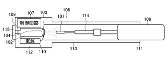
- FIG. 1 is a configuration diagram showing a configuration of a cleaning tool for an optical connector according to an embodiment of the present invention.
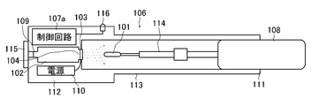
- FIG. 2A is a configuration diagram showing a configuration of another optical connector cleaning tool according to the embodiment of the present invention.
- FIG. 2B is a configuration diagram showing a configuration of another optical connector cleaning tool according to the embodiment of the present invention.
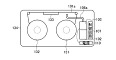
- FIG. 3A is a configuration diagram showing a configuration of another optical connector cleaning tool according to the embodiment of the present invention.
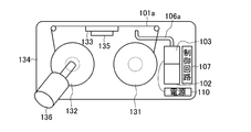
- FIG. 3B is a configuration diagram showing a configuration of another optical connector cleaning tool according to the embodiment of the present invention.
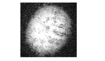
- FIG. 4A is a photograph showing a result of observing an end surface of a dirty optical connector.
- FIG. 4A is a photograph showing a result of observing an end surface of a dirty optical connector.
- FIG. 4B is a photograph showing the result of observing the end surface of the optical connector as a result of cleaning the end surface of the dirty optical connector with the conventional dry-type optical connector cleaning tool.
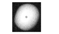
- FIG. 4C is a photograph showing the result of observing the end surface of the optical connector as a result of cleaning the dirty end surface of the optical connector with the optical connector cleaning tool according to the embodiment.
- This optical connector cleaning tool atomizes the cleaning unit 101 capable of absorbing (or adsorbing) the cleaning liquid 121, a container 102 containing the cleaning liquid 121, and the cleaning liquid 121 contained in the container 102 by ultrasonic atomization. And an atomizer 103.
- the container 102 includes a liquid supply port 104.
- the atomizer 103 is provided at the liquid supply port 104 of the container 102.
- the optical connector cleaning tool includes a supply unit 106 that supplies (sprays) the mist of the cleaning liquid 121 atomized by the atomizer 103 toward the cleaning unit 101.
- the cleaning unit 101 is composed of, for example, a cleaning cloth bag made of ultrafine fibers (see Patent Document 1).
- the cleaning unit 101 can also be configured by a brush made of a fiber bundle of a plurality of synthetic fiber filament yarns.
- the cleaning unit 101 can also be made of urethane foam.
- the cleaning unit 101 is attached to the tip of the grip unit 108.
- the cleaning unit 101 can also be made of a strip-shaped cloth (see Patent Documents 2 and 3).
- the atomizer 103 has an atomization separation unit 105 that covers the liquid supply port 104 and passes the mist without passing the liquid.
- the atomization separation unit 105 for example, the atomizer 103 can be made of piezoelectric ceramics made of polycrystalline ceramics produced by sintering powder of titanium oxide, barium oxide, or the like. By making a part of the atomizer 103 made of this polycrystalline ceramic thinner, the atomization separation unit 105 can be obtained.
- an atomization unit “NBC103SL” manufactured by Kado Co., Ltd. can be used as the atomizer 103, for example, a piezo ultrasonic humidifier disk with mesh holes manufactured by PZT can be used (see Non-Patent Document 1).
- the cleaning tool for optical connector also includes a control circuit 107 that controls the operation time of the atomizer 103.
- the control circuit 107 controls the operation time of the atomizer 103 at the set time.
- the control circuit 107 can be configured by a programmable logic device such as a microcomputer, an ASIC (Application Specific Integrated Circuit), or an FPGA (field-programmable gate array), for example.
- the atomizer 103 By applying an AC voltage with a frequency of 20 kHz or more to the electrode (not shown) provided on the atomizer 103, which is a piezoelectric ceramic, from the power supply 110, the atomizer 103 (atomization separation unit 105) vibrates. Ultrasonic waves are generated. When ultrasonic waves are emitted from the atomization separation unit 105 in this way, as is well known, the ultrasonic atomization is performed from the cleaning liquid 121 that is in contact with the atomization separation unit 105 on the liquid supply port 104 side. Fine droplets (mist) of about several ⁇ m are generated by chemical separation. The mist passes through the atomization separation unit 105 and is discharged to the supply unit 106 side.
- the amount of mist generated by the above can be controlled by the time during which the atomizer 103 is generating ultrasonic waves (the time during which it is operating).
- the control circuit 107 controls the operation time of the atomizer 103 at the set time to control the amount of mist of the cleaning liquid supplied from the atomization separation unit 105 to the supply unit 106. To do. For example, by turning on a switch (not shown), the control circuit 107 operates, and an AC voltage is applied from the power supply 110 to the electrodes provided in the atomizer 103 for a set time. While the AC voltage is being applied from the power supply 110 to the electrodes provided in the atomizer 103, the mist of the cleaning liquid atomized by the atomizer 103 is supplied toward the cleaning unit 101.
- a plurality of different times are set in the control circuit 107 to generate a mist of the cleaning liquid, and a plurality of test bodies in which the cleaning unit 101 is wetted with the cleaning liquid are produced under each condition.
- Test cleaning of the end face of the optical connector is carried out for each of the plurality of prepared test bodies.
- the time during which an appropriate amount of cleaning liquid is supplied to the cleaning unit 101 is obtained. The time thus obtained is set in the control circuit 107.
- an appropriate amount of cleaning liquid can be supplied to the cleaning unit 101.
- the supply unit 106 includes a tube 113 having an opening into which the cleaning unit 101 is inserted at one end 111.
- the atomizer 103 is provided at the other end 112 of the cylinder 113. Further, the cleaning unit 101 is inserted from one end 111 of the cylinder 113.
- the cleaning unit 101 is connected to the gripping unit 108 via the connecting unit 114.
- the container 102, the control circuit 107, and the power supply 110 are housed on the side of the other end 112 of the cylinder 113.
- the container 102 includes a liquid introduction hole 109 and a lid 115 that can be inserted into and removed from the liquid introduction hole 109. The mist atomized by the atomizer 103 is supplied toward the cleaning unit 101 inserted in the tube 113.
- the mist can be stably supplied to the cleaning unit 101.
- a fibrous body (not shown) is provided in the container 102 so as to contact the atomizer 103, the fibrous body absorbs the cleaning liquid, so that the supply unit 106 of the optical connector cleaning tool is oriented horizontally.
- the mist can be ejected from the atomizer 103 even in an arbitrary direction such as a vertical direction.
- the cleaning unit 101 which has absorbed the cleaning liquid is struck against the coupling end face and the cleaning body 101 is rotated.
- an operator holds the grip unit 108 and manually rotates the grip unit together with the cleaning unit 101.
- a mechanism for mechanically rotating by a spring or the like is provided inside the grip portion 108, and an operator holds the grip portion 108 and rotates the cleaning unit 101.
- a mechanism for rotating an electric motor, a battery, or the like is provided in the grip portion 108, and an operator holds the grip portion 108 and rotates the cleaning unit 101.
- the cleaning unit 101 When the grip 108 is connected to the cylinder 113, the cleaning unit 101 is arranged at a predetermined position with respect to the atomizer 103. After the cleaning operation, the position of the cleaning unit 101 with respect to the atomizer 103 is also the same when wetting another replaced cleaning unit 101. This contributes to maintaining or adjusting the degree of wetting of the cleaning unit 101.
- the degree of wetting of the cleaning body 101 can be controlled by the time during which the sprayer 103 is operated, but it can also be adjusted by changing the position of the cleaning unit 101 with respect to the atomizer 103. Of course, it is possible to adjust the electric power supplied to the atomizer 103.
- This optical connector cleaning tool having a mechanism for notifying a humidified state suitable for cleaning until the cleaning unit 101 moistened with the cleaning liquid immediately after the mist is supplied is dried will be described. To do.
- This optical connector cleaning tool includes, in addition to the optical connector cleaning tool shown in FIG. 2A, a timer (not shown) built in the control circuit 107a for measuring the time after completion of mist supply, and immediately after completion of mist supply. It has an indicator 116 composed of an LED or the like for notifying the completion of mist supply by turning on the light. The timer may be provided separately from the control circuit.
- the indicator 116 lights up when the operation time controlled by the control circuit 107a has elapsed.
- the timer measures the set time (specified time) from the time when the operation time controlled by the control circuit 107a has elapsed (immediately after the completion of mist supply)
- the indicator 116 is turned off.
- the indicator 116 is turned off under the control of the control circuit 107a. It is possible to determine an appropriate value for this prescribed time based on the relationship between the time from the completion of mist supply and the observation result of the cleaning state of the end surface by a plurality of tests in advance. As a result, the state suitable for cleaning is maintained while the indicator 116 is lit.
- the optical connector cleaning tool includes a belt-shaped cleaning cloth (cleaning portion) 101a, a supply reel 131 on which the cleaning cloth 101a is wound, and a winding reel 132 for winding the cleaning cloth 101a.
- a guide plate 133 for pressing the cleaning cloth 101a extending from the supply reel 131 to the winding reel 132 against the end face of the optical connector (not shown) is provided.
- the supply reel 131, the winding reel 132, and the guide plate 133 are housed in a housing 134 (see Patent Document 2).
- the optical connector cleaning tool may include a conduit 106a as a supply unit.
- the mist of the cleaning liquid atomized by the atomizer 103 is transported to the cleaning cloth 101a by the conduit 106a.
- the projecting hole of the conduit 106a is arranged near the cleaning cloth 101a extending from the supply reel 131 to the winding reel 132.
- the mist atomized by the atomizer 103 and transported by the conduit 106a is discharged from the discharge hole and sprayed (supplied) to the cleaning cloth 101a.
- the atomizer 103 can be provided in the vicinity of the guide plate 133, the cleaning liquid can be directly sprayed on the cleaning cloth without using the conduit 106a.
- a cleaning tool for an optical connector having a mechanism for automatically starting cleaning in a humidified state suitable for cleaning between the time when the cleaning cloth 101a immediately after supplying the mist is wet and the time when it is dried will be described with reference to FIG. 3B.
- This optical connector cleaning tool is composed of a switch, a pressure sensor, and the like in addition to the optical connector cleaning tool shown in FIG. 3A, and a start signal generator 135 for generating a start signal to signal cleaning start, and a winding device.
- An actuator 136 such as a motor for automatically rotating the reel 132 is added, and these are connected to the control circuit 107 like the atomizer 103.
- the start signal generating unit 135 is configured by a pressure sensor as an example.
- the start signal generator 135 is provided below the guide plate 133 against which the connector to be cleaned is pressed.
- the start signal generator 135 detects the pressing.
- the control circuit 107 including the pressure sensor measures the pressure value due to the pressing, and when it determines that the measured pressure value has reached the pressing suitable for cleaning, the atomizer 103 is brought into an appropriate humidification state. Operate only for time.
- the control circuit 107 immediately rotates the motor 136 so as to wind the cleaning cloth 101a in an amount required for cleaning.
- the cleaning cloth 101a can be wound by rotating the motor 136 during the operation of the atomizer 103. If the winding amount required for this cleaning is set to the distance required for the end face of the optical connector to pass through the humidified area of the cleaning cloth, only wet cleaning can be performed. Further, by further increasing the distance so as to pass through the dry area of the cleaning cloth, it is possible to perform the wipe-up cleaning in which the dry cleaning is performed after the wet cleaning. As a result, a series of operations from the humidification to the cleaning of the cleaning cloth 101a are automatically performed within a fixed time, so that the cleaning cloth 101a can be cleaned in an appropriate humidified state at any time.
- FIG. 2B an example in which an indicator shows an appropriate over-humidity state for the optical connector cleaning tool shown in FIG. 2A
- FIG. 3B the optical connector cleaning tool shown in FIG.
- An example of a mechanism that performs humidification and cleaning is shown in. Both are means for cleaning in an appropriate humidified state, and since that means does not depend on the device, a switch and a motor are added to the optical connector cleaning tool of FIG. 2A to automatically clean from humidification within a fixed time. It is also possible to perform the above, and it is also possible to add an indicator to the optical connector cleaning tool of FIG. 3A to indicate an appropriate overhumid state. Of course, both can be added to one optical connector cleaning tool.
- the mist of the cleaning liquid atomized by the atomizer by ultrasonic atomization is supplied toward the cleaning unit, an appropriate amount of cleaning liquid is cleaned. Can be supplied to the department. As a result, according to the present invention, a high cleaning force is exerted even with respect to dirt attached to the coupling end surface of the optical connector.
- the cleaning body can be evenly moistened with the cleaning liquid. Further, according to the present invention, it is easy to control the degree of wetness of the cleaning body by the cleaning liquid, and the degree of wetness is reproduced with high accuracy. Further, according to the present invention, since the cleaning liquid is not heated, the cleaning liquid can be widely selected from water-soluble liquids to organic liquids. Further, since it is possible to suppress the excessive supply of the cleaning liquid, it is possible to perform cleaning many times with a small amount of cleaning liquid.
Landscapes
- Physics & Mathematics (AREA)
- General Physics & Mathematics (AREA)
- Optics & Photonics (AREA)
- Mechanical Coupling Of Light Guides (AREA)
- Cleaning In General (AREA)
- Cleaning By Liquid Or Steam (AREA)
Abstract
L'invention concerne un outil de nettoyage de connecteur optique qui est pourvu d'une partie de nettoyage (101), d'un récipient (102) pour recevoir une solution de nettoyage (121), et d'un atomiseur (103) pour atomiser la solution de nettoyage (121) logée dans le récipient (102) par atomisation ultrasonore. L'atomiseur (103) a une partie de séparation d'atomisation (105) pour transmettre un vapeur sans transmettre de liquide, la partie de séparation d'atomisation (105) recouvrant un orifice d'alimentation en liquide (104). L'outil de nettoyage est également pourvu d'un circuit de commande (107) pour commander le temps de fonctionnement de l'atomiseur (103) en fonction d'un temps défini.
Priority Applications (4)
| Application Number | Priority Date | Filing Date | Title |
|---|---|---|---|
| EP19909810.4A EP3913413B1 (fr) | 2019-01-18 | 2019-11-21 | Outil de nettoyage de connecteur optique |
| US17/421,268 US11880073B2 (en) | 2019-01-18 | 2019-11-21 | Optical connector cleaning tool |
| CN201980089227.9A CN113302530B (zh) | 2019-01-18 | 2019-11-21 | 光学连接器清洁工具 |
| US18/523,389 US12222558B2 (en) | 2019-01-18 | 2023-11-29 | Optical connector cleaning tool |
Applications Claiming Priority (2)
| Application Number | Priority Date | Filing Date | Title |
|---|---|---|---|
| JP2019-006688 | 2019-01-18 | ||
| JP2019006688A JP6650539B1 (ja) | 2019-01-18 | 2019-01-18 | 光コネクタ用清掃具 |
Related Child Applications (2)
| Application Number | Title | Priority Date | Filing Date |
|---|---|---|---|
| US17/421,268 A-371-Of-International US11880073B2 (en) | 2019-01-18 | 2019-11-21 | Optical connector cleaning tool |
| US18/523,389 Continuation US12222558B2 (en) | 2019-01-18 | 2023-11-29 | Optical connector cleaning tool |
Publications (1)
| Publication Number | Publication Date |
|---|---|
| WO2020149005A1 true WO2020149005A1 (fr) | 2020-07-23 |
Family
ID=69568290
Family Applications (1)
| Application Number | Title | Priority Date | Filing Date |
|---|---|---|---|
| PCT/JP2019/045543 Ceased WO2020149005A1 (fr) | 2019-01-18 | 2019-11-21 | Outil de nettoyage de connecteur optique |
Country Status (5)
| Country | Link |
|---|---|
| US (2) | US11880073B2 (fr) |
| EP (1) | EP3913413B1 (fr) |
| JP (1) | JP6650539B1 (fr) |
| CN (1) | CN113302530B (fr) |
| WO (1) | WO2020149005A1 (fr) |
Families Citing this family (3)
| Publication number | Priority date | Publication date | Assignee | Title |
|---|---|---|---|---|
| JP6650539B1 (ja) * | 2019-01-18 | 2020-02-19 | エヌ・ティ・ティ・アドバンステクノロジ株式会社 | 光コネクタ用清掃具 |
| US11899248B2 (en) * | 2020-03-06 | 2024-02-13 | Intuitive Surgical Operations, Inc. | Systems and methods for optical fiber cleaning and interface particle reduction |
| US20250269406A1 (en) * | 2022-04-20 | 2025-08-28 | Ntt Advanced Technology Corporation | Optical connector cleaning device |
Citations (8)
| Publication number | Priority date | Publication date | Assignee | Title |
|---|---|---|---|---|
| US20030169991A1 (en) * | 2002-03-11 | 2003-09-11 | Vyacheslav Malevanets | Cleaner for fiber optic connectors |
| JP2005511302A (ja) * | 2001-12-13 | 2005-04-28 | スリーエム イノベイティブ プロパティズ カンパニー | 光学表面を清浄するための液体噴霧装置および方法 |
| JP2006208481A (ja) | 2005-01-25 | 2006-08-10 | Ntt Advanced Technology Corp | 光コネクタ用クリーナー |
| JP2007035662A (ja) * | 2005-07-22 | 2007-02-08 | Honda Electronic Co Ltd | 微細霧化粒子洗浄装置 |
| US7215864B1 (en) * | 2006-07-24 | 2007-05-08 | All Optronics, Inc. | Low-cost portable fiber-optic connector cleaner |
| JP2011156481A (ja) * | 2010-02-01 | 2011-08-18 | Mitsubishi Electric Corp | 超音波霧化装置及びそれを備えた設備機器 |
| JP2013167875A (ja) | 2012-01-19 | 2013-08-29 | Ntt Advanced Technology Corp | 光コネクタ用清掃具 |
| JP2017217602A (ja) | 2016-06-07 | 2017-12-14 | 株式会社フジクラ | 清掃工具及び清掃方法 |
Family Cites Families (24)
| Publication number | Priority date | Publication date | Assignee | Title |
|---|---|---|---|---|
| GB803917A (en) | 1956-02-01 | 1958-11-05 | Gen Electric Co Ltd | Improvements in or relating to refrigerator condensers |
| US3816868A (en) * | 1971-12-21 | 1974-06-18 | Singer Co | Glass cleaning apparatus |
| JP3549610B2 (ja) * | 1995-04-13 | 2004-08-04 | 株式会社フジクラ | 光ファイバのクリーニング方法及び光ファイバクリーナ |
| US20020162582A1 (en) * | 2000-12-13 | 2002-11-07 | Ching Chu | Optical fiber connector system cleaning machine |
| JP2003200116A (ja) * | 2002-01-09 | 2003-07-15 | Ntt Advanced Technology Corp | 光コネクタ用清掃具 |
| JP2003232545A (ja) * | 2002-02-06 | 2003-08-22 | Dasukomu Aomori:Kk | 超音波式噴霧器およびその超音波式噴霧器に用いるヒノキチオール溶液の抽出方法 |
| US6865329B2 (en) | 2002-03-07 | 2005-03-08 | Fujikura Ltd. | Optical connector cleaning instrument and optical connector cleaning method |
| US6839935B2 (en) * | 2002-05-29 | 2005-01-11 | Teradyne, Inc. | Methods and apparatus for cleaning optical connectors |
| US6853794B2 (en) * | 2002-07-02 | 2005-02-08 | Lightel Technologies Inc. | Apparatus for cleaning optical fiber connectors and fiber optic parts |
| JP2004216221A (ja) * | 2003-01-10 | 2004-08-05 | Omc:Kk | 霧化装置 |
| KR20170016014A (ko) * | 2003-04-11 | 2017-02-10 | 가부시키가이샤 니콘 | 액침 리소그래피에 의한 광학기기의 세정방법 |
| US7837801B2 (en) * | 2006-06-06 | 2010-11-23 | Ksaria Corporation | Apparatus and method for cleaning an optical fiber |
| JP4728889B2 (ja) * | 2006-06-27 | 2011-07-20 | 日本電信電話株式会社 | 光ファイバ端面の清掃方法 |
| US20080028567A1 (en) * | 2006-08-03 | 2008-02-07 | The United States Of America As Represented By The Secretary Of The Navy | Cleaning device for fiber optic connectors |
| GB2458107A (en) * | 2008-03-03 | 2009-09-09 | Alker Optical Equipment Ltd | Method and apparatus for cleaning fibre optic connectors |
| JP5493074B2 (ja) * | 2008-06-16 | 2014-05-14 | 本多電子株式会社 | 超音波霧化分離装置 |
| US9910227B2 (en) * | 2014-12-11 | 2018-03-06 | Illinois Tool Works Inc. | Oscillating fiber optic cleaning tool |
| CN106540889B (zh) * | 2015-09-16 | 2019-05-28 | 泰科电子(上海)有限公司 | 擦拭系统 |
| CN105511026B (zh) * | 2015-10-15 | 2017-07-18 | 无锡百立德自动化有限公司 | 光纤头清理装置 |
| WO2018009802A1 (fr) * | 2016-07-08 | 2018-01-11 | Commscope Technologies Llc | Outil d'inspection de ferrule de fibre optique avec dispositif de détection et de nettoyage de contamination |
| CN110709123A (zh) * | 2017-05-31 | 2020-01-17 | 坪田实验室股份有限公司 | 保湿喷雾的喷雾装置和喷雾方法 |
| EP3814820B1 (fr) * | 2018-06-29 | 2023-11-29 | Corning Research & Development Corporation | Buse de pulvérisation, systèmes, et procédés de nettoyage de connecteurs de fibres optiques |
| MX2021002326A (es) * | 2018-08-29 | 2021-04-28 | Corning Inc | Boquillas y metodos de limpieza para conectores o adaptadores de fibra optica. |
| JP6650539B1 (ja) * | 2019-01-18 | 2020-02-19 | エヌ・ティ・ティ・アドバンステクノロジ株式会社 | 光コネクタ用清掃具 |
-
2019
- 2019-01-18 JP JP2019006688A patent/JP6650539B1/ja active Active
- 2019-11-21 US US17/421,268 patent/US11880073B2/en active Active
- 2019-11-21 WO PCT/JP2019/045543 patent/WO2020149005A1/fr not_active Ceased
- 2019-11-21 EP EP19909810.4A patent/EP3913413B1/fr active Active
- 2019-11-21 CN CN201980089227.9A patent/CN113302530B/zh active Active
-
2023
- 2023-11-29 US US18/523,389 patent/US12222558B2/en active Active
Patent Citations (8)
| Publication number | Priority date | Publication date | Assignee | Title |
|---|---|---|---|---|
| JP2005511302A (ja) * | 2001-12-13 | 2005-04-28 | スリーエム イノベイティブ プロパティズ カンパニー | 光学表面を清浄するための液体噴霧装置および方法 |
| US20030169991A1 (en) * | 2002-03-11 | 2003-09-11 | Vyacheslav Malevanets | Cleaner for fiber optic connectors |
| JP2006208481A (ja) | 2005-01-25 | 2006-08-10 | Ntt Advanced Technology Corp | 光コネクタ用クリーナー |
| JP2007035662A (ja) * | 2005-07-22 | 2007-02-08 | Honda Electronic Co Ltd | 微細霧化粒子洗浄装置 |
| US7215864B1 (en) * | 2006-07-24 | 2007-05-08 | All Optronics, Inc. | Low-cost portable fiber-optic connector cleaner |
| JP2011156481A (ja) * | 2010-02-01 | 2011-08-18 | Mitsubishi Electric Corp | 超音波霧化装置及びそれを備えた設備機器 |
| JP2013167875A (ja) | 2012-01-19 | 2013-08-29 | Ntt Advanced Technology Corp | 光コネクタ用清掃具 |
| JP2017217602A (ja) | 2016-06-07 | 2017-12-14 | 株式会社フジクラ | 清掃工具及び清掃方法 |
Also Published As
| Publication number | Publication date |
|---|---|
| EP3913413A4 (fr) | 2022-09-07 |
| EP3913413B1 (fr) | 2024-07-31 |
| CN113302530A (zh) | 2021-08-24 |
| JP2020115196A (ja) | 2020-07-30 |
| JP6650539B1 (ja) | 2020-02-19 |
| EP3913413A1 (fr) | 2021-11-24 |
| US20240094474A1 (en) | 2024-03-21 |
| US11880073B2 (en) | 2024-01-23 |
| CN113302530B (zh) | 2023-01-03 |
| US20220026642A1 (en) | 2022-01-27 |
| US12222558B2 (en) | 2025-02-11 |
| EP3913413C0 (fr) | 2024-07-31 |
Similar Documents
| Publication | Publication Date | Title |
|---|---|---|
| US12222558B2 (en) | Optical connector cleaning tool | |
| US20240351059A1 (en) | Aerosol-generating system comprising a vibratable element | |
| AU2018100587A4 (en) | Vacuum cleaner accessory tool configured to distribute mist | |
| JP7701927B2 (ja) | 複数のアトマイザーを含むエアロゾル発生器 | |
| US12017242B2 (en) | Atomiser assembly with oscillation chamber | |
| KR20180121777A (ko) | 흡연 장치 및 에어로졸 발생 방법 | |
| KR20210009307A (ko) | 분무기 조립체용 2층 메쉬 요소 | |
| KR20180111845A (ko) | 액체 에어로졸 형성 기재 식별을 갖는 에어로졸 발생 시스템 | |
| US20020074426A1 (en) | Atomizer and inhalator using same | |
| KR102679238B1 (ko) | 카트리지 및 이를 포함하는 에어로졸 생성 장치 | |
| JP2025178270A (ja) | トランスデューサのフィードバック制御を有するエアロゾル発生装置 | |
| WO2006129592A1 (fr) | Pulvérisateur électrostatique et soufflante l’utilisant | |
| KR20220096964A (ko) | 에어로졸 생성 장치 및 그의 동작 방법 | |
| JP2011075196A (ja) | ミスト生成器 | |
| JP2000245841A (ja) | アイケア用噴霧装置 | |
| US20260014587A1 (en) | Method and device for controlling driving circuit for vibrator | |
| RU2804294C2 (ru) | Генерирующая аэрозоль система, картридж для генерирующей аэрозоль системы и распылитель для распыления жидкого образующего аэрозоль субстрата для генерирования аэрозоля | |
| JP2023540416A (ja) | エアロゾル生成装置用カートリッジ及びそれを含むエアロゾル生成装置 | |
| RU2833155C1 (ru) | Устройство для генерирования аэрозоля с управлением преобразователем по обратной связи и способ его функционирования | |
| JP6338983B2 (ja) | 噴霧装置 | |
| JPH08280806A (ja) | 医療用ホースレス型スプレー装置 | |
| JP3939535B2 (ja) | 描画装置 | |
| RU2812692C2 (ru) | Курительное устройство и способ генерирования аэрозоля | |
| CN120091768A (zh) | 确定超声波振动器的状态的方法及执行该方法的电子装置 |
Legal Events
| Date | Code | Title | Description |
|---|---|---|---|
| 121 | Ep: the epo has been informed by wipo that ep was designated in this application |
Ref document number: 19909810 Country of ref document: EP Kind code of ref document: A1 |
|
| NENP | Non-entry into the national phase |
Ref country code: DE |
|
| ENP | Entry into the national phase |
Ref document number: 2019909810 Country of ref document: EP Effective date: 20210818 |