WO2020149009A1 - Dispositif de marquage et procédé de fabrication d'un produit doté de parties en saillie - Google Patents
Dispositif de marquage et procédé de fabrication d'un produit doté de parties en saillie Download PDFInfo
- Publication number
- WO2020149009A1 WO2020149009A1 PCT/JP2019/045773 JP2019045773W WO2020149009A1 WO 2020149009 A1 WO2020149009 A1 WO 2020149009A1 JP 2019045773 W JP2019045773 W JP 2019045773W WO 2020149009 A1 WO2020149009 A1 WO 2020149009A1
- Authority
- WO
- WIPO (PCT)
- Prior art keywords
- work
- dispenser
- marking device
- marking
- resin material
- Prior art date
- Legal status (The legal status is an assumption and is not a legal conclusion. Google has not performed a legal analysis and makes no representation as to the accuracy of the status listed.)
- Ceased
Links
Images


Classifications
-
- B—PERFORMING OPERATIONS; TRANSPORTING
- B05—SPRAYING OR ATOMISING IN GENERAL; APPLYING FLUENT MATERIALS TO SURFACES, IN GENERAL
- B05C—APPARATUS FOR APPLYING FLUENT MATERIALS TO SURFACES, IN GENERAL
- B05C11/00—Component parts, details or accessories not specifically provided for in groups B05C1/00 - B05C9/00
-
- B—PERFORMING OPERATIONS; TRANSPORTING
- B05—SPRAYING OR ATOMISING IN GENERAL; APPLYING FLUENT MATERIALS TO SURFACES, IN GENERAL
- B05C—APPARATUS FOR APPLYING FLUENT MATERIALS TO SURFACES, IN GENERAL
- B05C11/00—Component parts, details or accessories not specifically provided for in groups B05C1/00 - B05C9/00
- B05C11/10—Storage, supply or control of liquid or other fluent material; Recovery of excess liquid or other fluent material
-
- B—PERFORMING OPERATIONS; TRANSPORTING
- B05—SPRAYING OR ATOMISING IN GENERAL; APPLYING FLUENT MATERIALS TO SURFACES, IN GENERAL
- B05C—APPARATUS FOR APPLYING FLUENT MATERIALS TO SURFACES, IN GENERAL
- B05C5/00—Apparatus in which liquid or other fluent material is projected, poured or allowed to flow on to the surface of the work
-
- B—PERFORMING OPERATIONS; TRANSPORTING
- B05—SPRAYING OR ATOMISING IN GENERAL; APPLYING FLUENT MATERIALS TO SURFACES, IN GENERAL
- B05C—APPARATUS FOR APPLYING FLUENT MATERIALS TO SURFACES, IN GENERAL
- B05C9/00—Apparatus or plant for applying liquid or other fluent material to surfaces by means not covered by any preceding group, or in which the means of applying the liquid or other fluent material is not important
- B05C9/08—Apparatus or plant for applying liquid or other fluent material to surfaces by means not covered by any preceding group, or in which the means of applying the liquid or other fluent material is not important for applying liquid or other fluent material and performing an auxiliary operation
- B05C9/12—Apparatus or plant for applying liquid or other fluent material to surfaces by means not covered by any preceding group, or in which the means of applying the liquid or other fluent material is not important for applying liquid or other fluent material and performing an auxiliary operation the auxiliary operation being performed after the application
-
- B—PERFORMING OPERATIONS; TRANSPORTING
- B41—PRINTING; LINING MACHINES; TYPEWRITERS; STAMPS
- B41J—TYPEWRITERS; SELECTIVE PRINTING MECHANISMS, i.e. MECHANISMS PRINTING OTHERWISE THAN FROM A FORME; CORRECTION OF TYPOGRAPHICAL ERRORS
- B41J2/00—Typewriters or selective printing mechanisms characterised by the printing or marking process for which they are designed
- B41J2/005—Typewriters or selective printing mechanisms characterised by the printing or marking process for which they are designed characterised by bringing liquid or particles selectively into contact with a printing material
- B41J2/01—Ink jet
-
- B—PERFORMING OPERATIONS; TRANSPORTING
- B41—PRINTING; LINING MACHINES; TYPEWRITERS; STAMPS
- B41J—TYPEWRITERS; SELECTIVE PRINTING MECHANISMS, i.e. MECHANISMS PRINTING OTHERWISE THAN FROM A FORME; CORRECTION OF TYPOGRAPHICAL ERRORS
- B41J3/00—Typewriters or selective printing or marking mechanisms characterised by the purpose for which they are constructed
- B41J3/32—Typewriters or selective printing or marking mechanisms characterised by the purpose for which they are constructed for printing in Braille or with keyboards specially adapted for use by blind or disabled persons
Definitions
- the present invention relates to a marking device and a method for manufacturing a product with protrusions, and in particular, a marking device for marking dot-shaped protrusions using a dispenser, and a product with protrusions by marking dot-shaped protrusions using a dispenser.
- the present invention relates to a method for manufacturing a product with protrusions to be manufactured.
- Patent Document 1 discloses a braille display plate creating device that creates a braille display plate by drawing Braille using a dispenser. Specifically, in the braille display board creating apparatus disclosed in Patent Document 1, a drawing tool is used to draw and cure a black ink with a resin, and then a dispenser is used to draw and cure the braille of the resin. ..
- the present invention has been made to solve such a problem, and a marking device capable of marking dot-like protrusions on demand on a work conveyed in-line, and a dot-like protrusion are formed. It is an object of the present invention to provide a method for manufacturing a product with a protrusion.
- one mode of a marking device is a marking device for marking a dot-shaped projection by ejecting droplets onto each of a plurality of works continuously conveyed by a conveying path.
- a jet-type dispenser that can eject the droplets in a non-contact manner at a constant cycle, and the droplets can be delivered to the dispenser at a plurality of timings in the constant cycle based on the marking pattern of the protrusion.
- a non-ejection timing at which the droplet is not ejected to the dispenser and a control unit that transmits an ejection command to the dispenser at the ejection timing, the dispenser receiving from the control unit.
- the droplets are ejected based on the ejection command.
- one aspect of the method for manufacturing a product with protrusions according to the present invention is to use a jet type dispenser capable of ejecting droplets in a non-contact manner at a constant cycle, and to form a dot-like pattern on a work conveyed by a conveyance path.
- -Dot-shaped protrusions can be marked on-demand on the work conveyed in-line.
- FIG. 1 is a schematic configuration diagram of a marking device according to the first embodiment.
- FIG. 2 is a functional block diagram of the marking device according to the first embodiment.
- FIG. 3 is a flowchart illustrating the operation of the marking device according to the first embodiment.
- FIG. 4 is a diagram illustrating a marking device according to the first modification.
- FIG. 5 is a schematic configuration diagram illustrating a marking device according to the second modification.
- FIG. 6 is an enlarged perspective view of a dispenser for explaining the marking device according to the second embodiment.
- FIG. 7 is a diagram for explaining the operation of the marking device according to the second embodiment.
- a method of marking a protrusion on a work As a method of marking a protrusion on a work, a method of using embossing by backing is known. For example, Braille for distinguishing alcoholic beverages from others is marked on the top surface of a beverage can by the above method.
- the above method has limitations such as the material that can be deformed by the lining and the thickness. Further, the above method is complicated because it is necessary to provide an embossing process separately from the production line.
- a method of applying a resin material and marking the protrusions on the work is known.
- This is known as, for example, a silk screen that marks a protrusion by applying and curing a resin material in accordance with the hole using a plate-shaped screen in which a hole is provided in a shape for marking the protrusion.
- a silk screen that marks a protrusion by applying and curing a resin material in accordance with the hole using a plate-shaped screen in which a hole is provided in a shape for marking the protrusion.
- a method of applying the resin material there is a method of discharging the resin material from a nozzle that moves along a position where the protrusion is desired to be marked, as disclosed in Patent Document 1.
- a contact method is used in which the dispenser tip from which the resin material is fed is brought into contact with the surface to be marked and applied.
- the relative positional relationship between the marked surface and the dispenser needs to be kept constant while the dispenser is in contact.
- each of the mass-produced workpieces has manufacturing variations, and the position of the marked surface is not stable. Therefore, for example, when a resin material is applied to the top surface of a work, a dispenser that delivers the resin material from above the top surface comes into contact with the work, and the application amount of the resin material is not stable due to variations in the contact area. Occurs. For this reason, when using the above contact-type dispenser, the positions of the work and the dispenser need to be strictly controlled.
- the marking device according to the present invention and the method for manufacturing a product with protrusions in which protrusions are marked on the work are made based on such knowledge.
- the marking device can mark a dot-like protrusion on a work conveyed inline on demand.
- each diagram used for explanation is a schematic diagram, and is not necessarily strictly illustrated. Further, in each of the drawings, substantially the same configurations are denoted by the same reference numerals, and redundant description may be omitted or simplified.
- FIG. 1 is a schematic configuration diagram of a marking device 100 according to the first embodiment.
- FIG. 1 shows an x-axis, a y-axis, and a z-axis, which are orthogonal to each other.
- the marking device 100 is arranged such that the belt surface of the transport path (that is, the transport surface) is on the xy plane and the movement direction of the work 20 is the x-axis plus direction.
- the side on which the work 20 is placed is the z-axis positive direction (or the upward direction), and the opposite side is the z-axis negative direction (or the downward direction). To do.
- FIG. 1A is a top view of a production line 200 including the marking device 100.
- FIG. 1B is a view of the production line 200 including the marking device 100 as viewed from the side (the y-axis minus direction).
- 2 is a functional block diagram of the marking device 100 according to the first embodiment.
- the work 20 and the hidden part of the encoder 11 are indicated by broken lines.
- the hidden part of the work 20 is indicated by a broken line.
- the marking device 100 is installed in the production line 200 of the work 20, and the resin material is discharged to the cap 20a of the work 20 conveyed in the production line 200 and cured. Mark the dot-shaped protrusions.
- the production line 200 of the work 20 is, for example, a line in which the work of attaching the cap 20a after filling the liquid which is the content of the work 20 is performed, and the plurality of work 20 to which the cap 20a is attached is continuously conveyed. It is something.
- the liquid of the content will be described as a drink.
- the contents may be liquids other than beverages, such as fats and oils, detergents, or paints.
- the top surface of the attached cap 20a is used as a marking surface, and a dot-shaped protrusion is marked on the marking surface of each of the plurality of works 20.
- the top surface of the cap 20a is a surface parallel to the transport surface of the transport path. Therefore, the workpiece 20 in the present embodiment will be described assuming that the surface to be marked is a surface parallel to the transport surface of the transport path.
- the work 20 is, for example, a main body of an article, a container filled with contents, or an article in which an article is packaged in an outer box or the like.
- the production line 200 may be a line before filling the contents in which the above container is prepared, a line after being packaged in an outer box, or the like. Therefore, the marking device 100 may be installed in the production line 200 corresponding to any step in the production of a series of products with protrusions.
- the resin material (that is, droplets) before curing is applied to any surface (marked surface) of the body of the article, the container filled with the contents, or the package such as the exterior film or the exterior box.
- the work 20 may have any shape.
- surface treatment such as coating for improving the fixing property of the resin material may be appropriately performed.
- the marking device 100 includes an encoder 11, a detection unit 12, a dispenser 13, a control unit 14, an acquisition unit 15, a vertical belt 16, and a curing unit 17.
- the marking device 100 is installed in the production line 200 on a conveyance path for conveying the work 20.
- the transport path is specifically a belt type conveyor 21.
- the transfer path is not limited to this, and may be a roller type conveyor, a linear type conveyor, or a transfer robot.
- the transport path may have any configuration as long as the work 20 is moved along a predetermined route.
- the conveyor 21 moves the workpiece 20 placed on the belt surface 21a at a speed of 400 mm/s in the moving direction (x-axis plus direction) indicated by the one-dot chain line in FIG.
- the moving speed of the work 20 by the conveyor 21 is not limited to this, and may be higher or lower than 400 mm/s. Such limitation on the moving speed of the work 20 will be described together with the dispenser 13 described later.
- a plurality of works 20 are placed on the belt surface 21a of the conveyor 21 at intervals of 200 mm on average (that is, pitch).
- the marking device 100 can mark dot-like protrusions on each of the plurality of works 20. That is, the marking device 100 can mark the protrusions on 120 workpieces 20 per minute.
- the interval at which the work 20 is placed is not limited to the above, and may be wider or narrower than 200 mm.
- the interval at which the work 20 is placed will be described later together with the movement speed of the work 20 together with the dispenser 13.
- the works 20 onto which the resin material is discharged may be arranged at a constant interval, or may be arranged irregularly with the intervals being varied.
- the main body 10 of the marking device 100 which includes the detection unit 12, the dispenser 13, the control unit 14, and the acquisition unit 15, is installed above the belt surface 21 a of the conveyor 21 by a predetermined distance.
- the predetermined distance is a distance through which the work 20 conveyed by the conveyor 21 can pass, and is set according to the size of the work 20 to which the marking device 100 is applied in the z-axis direction. Further, the predetermined distance is configured so as to be able to correspond to the position deviation of the surface to be marked of the work 20 in the z-axis direction.
- the lower end of the nozzle 13a of the dispenser 13 that discharges the resin material is at a predetermined distance from the surface to be marked of the work 20. Is set to a value such that they are separated by about 5 to 10 mm.
- the main body 10 of the marking device 100 is provided with columns extending in the vertical direction on both sides sandwiching the conveyor 21 in the y-axis direction, for example, and is supported by the columns so that the columns are spaced a predetermined distance above the conveyor 21. It is installed.
- the support column has a mechanism capable of expanding and contracting in the vertical direction
- the position of the main body unit 10 in the vertical direction can be appropriately set according to the size of the work 20.
- the main body 10 may be configured to be suspended from above without providing such a support.
- a suspending mechanism may be configured to be suspended from a ceiling of a building having the production line 200 by means of a chain or the like.
- the encoder 11 is provided in the drive unit 21b that operates the conveyor 21, and is connected to the control unit 14 described below so as to be communicable.
- the encoder 11 is realized by, for example, a servo motor.
- the encoder 11 detects the operation of the conveyor 21 and generates (outputs) a pulse corresponding to the operation.
- the generated pulse is converted into the drive amount of the drive unit 21b by counting the pulse wave number, and the operation amount of the conveyor 21 (in other words, the movement amount of the work 20) is calculated. Therefore, the movement amount of the work 20 can be detected by the encoder 11.
- the pulse generated by the encoder 11 is received by the control unit 14, and the cycle of the pulse is used as a master clock (that is, a fixed cycle). Therefore, the control unit 14 can calculate the movement amount of the work 20 by counting the master clock.
- the pulse generated by the encoder 11 has a frequency higher than the maximum discharge frequency in discharging the resin material by the dispenser 13 described later.
- the pulse generated by the encoder 11 has a higher resolution than the discharge of the resin material by the dispenser 13. Therefore, the ejection of the resin material controlled based on the pulse generated from the encoder 11 is controlled with sufficient accuracy for the ejection of the resin material from the dispenser 13.
- the encoder 11 is not limited to being installed at the drive unit 21b of the conveyor 21, and may be a rotary encoder that contacts the belt surface 21a of the conveyor 21 and detects the movement of the work 20, for example.
- the detection unit 12 is included in the main body 10 of the marking device 100, and detects the position of the work 20 when the work 20 placed on the conveyor 21 is conveyed along with the operation of the conveyor 21. More specifically, the detection unit 12 is realized by means such as image recognition using a camera, a processor, and a memory. For example, the detection unit 12 detects the position of the work 20 in the image acquired by the camera by using the software stored in the memory. Such image recognition is performed by recognizing the feature of the work 20 (or the marker attached to the work 20) registered in the software in advance.
- Such a detector 12 is installed, for example, on the upstream side (minus side in the x-axis direction) of the dispenser 13 described later. Further, the detection unit 12 can accurately discharge the resin material by photographing the direction perpendicular to the transport surface and detecting the position of the work 20. That is, after detecting that the work 20 is at the position corresponding to the detection unit 12, and after the time required for moving from the position where the detection unit 12 is installed to the landing position of the resin material discharged from the dispenser 13, A resin material is discharged from the dispenser 13.
- the above-mentioned camera may be configured to be capable of photographing the landing position of the resin material discharged by the dispenser 13 installed on the downstream side. That is, the above camera may be configured by using a wide-angle lens such that the landing position falls within the angle of view. Further, the above-mentioned camera may be configured to be installed on the upstream side and arranged such that the axial direction of the lens is inclined toward the landing position on the downstream side, and installed on the downstream side to the landing position on the upstream side. The configuration may be such that the axial direction of the lens is inclined.
- the detector 12 may be arranged at any position as long as the landing position is within the angle of view of the camera. In this case, the resin material is discharged from the dispenser 13 when the position of the work 20 detected by the detection unit 12 matches a preset position.
- the detection unit 12 is communicatively connected to the control unit 14 and transmits the detected position of the work 20 to the control unit 14.
- the detection unit 12 may transmit the simple position of the work 20, or may be configured to transmit that the preset position and the detected position of the work 20 match.
- the detection unit 12 may be configured by a distance sensor using reflection of sound waves or infrared rays instead of the camera.
- it may be configured by an infrared transmission unit and a reception unit passing sensor of the work 20 arranged so as to sandwich the conveyor 21 in a direction (y-axis direction) orthogonal to the conveyance direction of the work 20 by the conveyor 21. Good.
- a configuration is used in which the fact that the work 20 has passed a preset position (that is, the installation position of the passage sensor in the transport direction) is transmitted to the control unit 14.
- the dispenser 13 is a device that is included in the main body 10 of the marking device 100 and discharges the resin material to the work 20 in a non-contact manner.
- the dispenser 13 can discharge the resin material at a constant cycle by a jet method.
- the discharge of the resin material from the dispenser 13 is performed by a piezo jet method, but a thermal jet method may be used. Further, any method may be used as long as the resin material can be discharged in a non-contact manner with high responsiveness.
- the dispenser 13 is communicably connected to the control unit 14, and discharges the resin material based on a discharge command received from the control unit 14 for causing the dispenser 13 to discharge the resin material.
- the dispenser 13 has a storage chamber for storing a resin material, a piezo element, and a nozzle 13a.
- a voltage is applied to the internal electrodes of the piezo element, and the piezo element is deformed.
- the piezo element is in contact with the storage chamber and deforms to press the contact surface of the storage chamber.
- the pressing reduces the volume of the storage chamber and increases the internal pressure of the storage chamber. Thereby, the internal pressure escapes to the nozzle 13a that communicates the storage chamber with the outside, and at that time, a part of the resin material in the storage chamber is discharged.
- the piezo element restores to its original shape and the internal pressure of the storage chamber decreases, so that the resin material communicating with the storage chamber different from the nozzle 13a
- the storage chamber is refilled with the resin material via the supply pipe.
- the dispenser 13 repeats such a discharge operation each time a discharge command is received, and discharges one droplet of resin material for each discharge command.
- the resin material discharged from the dispenser 13 is, for example, a high-viscosity material having a viscosity of 10 Pa ⁇ s or more and 2000 Pa ⁇ s or less. More preferably, the resin material is a high-viscosity material having a viscosity of 15 Pa ⁇ s or more and 2000 Pa ⁇ s or less.
- the maximum discharge frequency in discharging the resin material by the dispenser 13 will be described.
- the ejection frequency required for the dispenser 13 that is, how many droplets of resin material can be ejected per second
- the ejection frequency required for the dispenser 13 that is, how many droplets of resin material can be ejected per second
- the interval between each of the plurality of works 20 placed on the conveyor 21 is defined by the moving speed of the works 20 and the number of works 20 to be marked.
- the works 20 are arranged at an average distance of 200 mm.
- the moving speed of the work 20 is proportional to the interval at which the works 20 are placed when marking the same number of the works 20 within the same time, and if the moving speed is doubled, the work 20 is placed. The spacing is also doubled.
- the required ejection frequency is determined depending on the moving speed of the work 20 by the conveyor 21 and the interval of each droplet ejection on one work 20.
- Any dispenser 13 having a maximum discharge frequency equal to or higher than the required discharge frequency can be preferably used.
- the dispenser 13 may be used.
- the marking device 100 will be described as including the dispenser 13 having a maximum ejection frequency of 1000 Hz as an example. That is, if only one droplet is ejected on one work 20, the projections can be marked on 60,000 works 20 per minute. Further, if the configuration is such that two or more droplets are ejected on one workpiece 20 and the interval between droplets is 2.1 mm, it is possible to cope with the moving speed of the workpiece 20 of 2100 mm/s.
- the dispenser 13 discharges the high-viscosity resin material as described above. Therefore, the heating device may be provided in a storage chamber or in a tank of resin material to reduce the viscosity of the resin material and improve the discharge performance. Further, the cooling device may be provided in a storage chamber or in a tank of resin material to increase the viscosity of the resin material so that the resin material can easily maintain its three-dimensional shape after landing on the marking surface. Such an additional device may be appropriately configured according to the specifications of the dispenser 13 used for marking and the resin material. When the resin material is composed of a material having high thixotropy, the dispenser 13 may be provided with a stirring device in a storage chamber, a tank of the resin material, or the like.
- the control unit 14 is a processing device including a processor and a memory, and is included in the main body unit 10 of the marking device 100.
- the control unit 14 transmits a discharge command for discharging the resin material to the dispenser 13 based on the movement amount of the work 20 based on the pulse received from the encoder 11 and the position of the work 20 received from the detection unit 12.
- control unit 14 uses the pulse cycle acquired from the encoder 11 as a master clock, determines the discharge timing of the resin material, and sends a discharge command to the dispenser 13. More specifically, the control unit 14 acquires the pulse cycle from the encoder 11 and divides a plurality of timings for each cycle into ejection timing and non-ejection timing. At this time, the control unit 14 divides the ejection timing and the non-ejection timing based on the marking pattern of the protrusion acquired by the acquisition unit 15 described later.
- the discharge timing is a timing at which the dispenser 13 discharges the resin material
- the non-discharge timing is a timing at which the dispenser 13 does not discharge the resin material.
- the control unit 14 generates a timing chart including the ejection timing and the non-ejection timing thus divided from the plurality of timings, and transmits the ejection command to the dispenser 13 at the ejection timing on the timing chart. As a result, the control unit 14 causes the dispenser 13 to discharge the resin material according to the marking pattern of the protrusion.
- the acquisition unit 15 is a device that acquires information indicating a marking pattern, and is included in the main body unit 10 of the marking device 100.
- the acquisition unit 15 transmits information indicating the acquired marking pattern to the control unit 14. Therefore, the acquisition unit 15 is communicatively connected to the control unit 14, and also communicatively connected to the external device 22 that generates information indicating the marking pattern.
- the acquisition unit 15 is wirelessly connected to the external device 22 in a communicable manner, but may be wired to be connected.
- the external device 22 is, for example, a user interface such as a touch panel provided in the marking device 100.
- the marking pattern of the protrusion input by the user via the touch panel is included in the information indicating the marking pattern, and is acquired by the acquisition unit 15.
- the external device 22 may be a mobile terminal, or may be configured to send information indicating a marking pattern generated by an application stored in the mobile terminal to the acquisition unit 15.
- the vertical belt 16 has at least two belts 16a whose belt surfaces face each other and a pulley 16b for rotating at least two belts 16a.
- the vertical belt 16 includes at least two belts from both sides in a direction (y-axis direction) orthogonal to the moving direction of the work 20 by the conveyor 21 in a top view seen from the direction in which the conveyor 21 and the work 20 overlap (that is, from above). It is arranged so as to sandwich the work 20 by the belt surface of 16a.
- the vertical belt 16 holds the work 20 and suppresses the deviation of the marking surface due to the movement of the work 20 by the conveyor 21 and the like.
- the vertical belt 16 is preferably synchronized with the movement of the work 20 by the conveyor 21. That is, the pulley 16b of the vertical belt 16 is configured to rotate at least two belts 16a at a speed corresponding to the moving speed of the work 20 by the conveyor 21.
- the drive force may be shared by an appropriate power transmission means such as a gear.
- the vertical belt 16 may not be provided.
- a guide rail that partially suppresses the shake of the work 20 in the y-axis direction may be provided.
- the curing unit 17 is a device including a curing unit for curing the three-dimensional shape of the discharged resin material.
- the resin material is composed of an ultraviolet light curable resin. That is, it is necessary to irradiate with ultraviolet light in order to cure the resin material. Therefore, the curing unit 17 includes a light source that irradiates the three-dimensional shape of the resin material discharged onto the marking surface of the work 20 with ultraviolet light.
- the curing unit 17 extends along the moving direction of the work 20 by the conveyor 21 so that the ultraviolet light is irradiated for a necessary time in accordance with the amount of the resin material discharged onto the marking surface of the work 20.
- the curing unit 17 may be controlled by the control unit 14. More specifically, the control unit 14 controls the curing unit 17 only for a required curing time from the time when the work 20 enters the ultraviolet irradiation range of the curing unit 17 depending on the amount of the discharged resin material and the position of the work 20.
- the light source may be turned on, and the light source may be turned off when the curing time has elapsed.
- the control unit 14 may also control the emission intensity of the light source.
- the curing unit 17 may be replaced with an apparatus that works to appropriately cure the resin material, depending on the curing characteristics of the resin material.
- FIG. 3 is a flowchart illustrating the operation of the marking device 100 according to the first embodiment.
- the acquisition unit 15 acquires information indicating the marking pattern of the protrusion to be marked on the product with protrusions (S101). This is performed by the acquisition unit 15 receiving information indicating the marking pattern of the external device 22 by communicating with the external device 22. The information indicating the acquired marking pattern is further transmitted to the control unit 14 and stored in the memory included in the control unit 14.
- the control unit 14 reads out the information indicating the stored marking pattern, and generates a timing chart in which ejection timing and non-ejection timing are arranged according to the marking pattern.
- the control unit 14 detects the movement amount of the work 20 from the pulse generated by the encoder 11 (S102). Specifically, the control unit 14 receives the pulse transmitted from the encoder 11, and uses the period of the pulse as a master clock to count the master clock, whereby the control unit 14 detects the movement amount of the work 20 moved by the conveyor 21.
- the control unit 14 updates the generated timing chart based on the detected movement amount of the work 20. More specifically, the length between the ejection timings included in the timing chart or a plurality of timings that are non-ejection timings is set, and the time between each ejection or non-ejection and the next ejection or non-ejection is set. The distance that the work 20 moves is set.
- the control unit 14 starts detecting the movement amount of the work, and thereafter continuously detects the movement amount of the work 20. That is, when there is a change in the operation amount of the conveyor 21, the control unit 14 receives a pulse with a changed cycle, and the master clock changes in synchronization with this.
- the moving distance of the work 20 between each of the plurality of timings set on the timing chart is specified based on the master clock. That is, the timing chart specifies how many pulse wave numbers the encoder 11 generates between the ejection or non-ejection of the resin material and the next ejection or non-ejection. Therefore, the control unit 14 detects the fluctuation of the movement amount of the work 20 from the fluctuation of the master clock and updates the timing chart, so that the resin material can be accurately discharged regardless of the fluctuation of the operation amount of the conveyor 21. Can be controlled.
- control unit 14 divides the plurality of timings on the master clock into the ejection timing and the non-ejection timing based on the marking pattern by the processing up to this point, and the timing including the ejection timing at which the resin material can be accurately ejected. Generating a chart.
- the detection unit 12 detects the position of the work 20 moved by the conveyor 21 by image recognition (S103). More specifically, on the upper surface of the work 20 (the surface on which the cap 20a is attached), a marker preprinted on a part of the plus side of the cap 20a in the x-axis direction is recognized by image recognition and acquired. The position of the work 20 is detected based on where the position of the marker is in the image displayed. The detected position of the work 20 is transmitted to the control unit 14. Such detection of the position of the work 20 is continuously executed. Therefore, the detection unit 12 starts the position detection of the work, and thereafter continuously transmits the position of the work 20.
- image recognition S103
- the first ejection timing is based on the time point when the position of the work 20 detected by the detection unit 12 coincides with a predetermined position set in advance. That is, the time when the time required for the work 20 to move from the predetermined position to the position corresponding to the nozzle 13a of the dispenser 13 has elapsed is the first discharge timing. The time required for such movement is calculated based on the movement amount of the work 20 based on the pulse received from the encoder 11.
- the control unit 14 sets 1 on the timing chart.
- a control step (S104) of transmitting a discharge command at the discharge timing of the second time to the dispenser 13 is performed.
- the dispenser 13 performs a discharge step (S105) of discharging the resin material in a non-contact manner with the work 20 according to the received discharge command.
- the discharge amount of the resin material is three-dimensional by the solvent that volatilizes during curing and the resin material that is caused by the fluidity so that the height of the marked protrusion is higher than at least 0.5 mm. It is set in consideration of the radial spread of the shape.
- the predetermined position is the processing time from generation, update, transmission/reception, and reception of the timing chart to the start of the resin material ejection operation, and the flight time from the ejection of the resin material to the impact of the resin material. , It is set considering the time lag. Therefore, in addition to the distance to the position corresponding to the nozzle 13a of the dispenser 13, the predetermined position is set to the upstream side (minus side) in the x-axis direction by the distance corresponding to the movement distance of the work 20 within the time lag.
- control unit 14 transmits an ejection command at each ejection timing on the timing chart (S104), and causes the dispenser 13 to perform an operation of ejecting the resin material (S105). Further, as described above, when the fluctuation of the movement amount of the conveyor 21, that is, the fluctuation of the movement amount of the work 20 is detected, the dispenser 13 is transmitted from the control unit 14 at the ejection timing based on the updated timing chart. The discharge command is received and the resin material is discharged. In this way, the marking device 100 discharges the resin material on the surface to be marked according to the marking pattern. Therefore, the marking device 100 can mark the dot-shaped projection on the work 20 conveyed inline on demand.
- the control unit 14 causes the discharge You may implement the control step (S104) which transmits a command to the dispenser 13.
- the resin material may be discharged from the dispenser 13 at constant intervals. Therefore, the discharge command may be transmitted to the dispenser 13 at regular intervals based on the pulse transmitted from the encoder 11 regardless of the detection unit 12 (S104).
- an arrangement device that aligns the works 20 may be provided, and the positions of the plurality of works 20 may be aligned with the discharge intervals of the resin material by the dispenser 13 by the alignment device.
- Such an aligning device is realized by stopping the movement of each of the plurality of works 20 at equal intervals against the operation of the conveyor 21 by each of a plurality of comb-teeth-shaped holders arranged at equal intervals. After that, the plurality of holders are released at the same time to return the work 20 to the movement by driving the conveyor 21 again.
- the marking device 100 marks the work 20 conveyed in-line with the dot-shaped protrusions on demand even in such a configuration. be able to.
- the resin material discharged onto the marked surface of the work 20 by the above operation is a high-viscosity material as described above, and therefore the conveyor 21 continues to move while having a three-dimensional shape.
- a curing unit 17 is installed further downstream in the moving direction of the work 20 by the conveyor 21, and the work 20 after the resin material has been discharged moves to a position corresponding to the curing unit 17 as the conveyor 21 operates. Then, the three-dimensional shape made of the resin material is cured. More specifically, the curing unit 17 includes a light source that emits ultraviolet light, and is always in a lighting state.
- the resin material in the present embodiment is an ultraviolet light curable resin as described above, and is irradiated with ultraviolet light when passing through the position corresponding to the curing portion 17 (S106). The three-dimensional shape of the material is hardened.
- the color of the protrusion formed by curing the resin material is, for example, the same color as the surface to be marked, but is not limited to this.
- the formed protrusion may have a color different from that of the surface to be marked.
- the formed protrusion may be transparent, and the protrusion may be transmitted so that the surface to be marked can be visually recognized by a healthy person.
- information that can be visually recognized by a healthy person may be printed on the surface to be marked by color arrangement and shading.
- the color of the surface to be marked can be configured in any color without limitation.
- the dispenser 13 is configured to be capable of scanning in the direction (y-axis direction) orthogonal to the moving direction of the work piece 20 in a top view
- the dot-shaped protrusions are arranged in 3 rows and 2 columns.
- the 6 points can be marked. That is, it is also possible to mark a plurality of projections in 3 rows and 2 columns in units of 6 points on the surface to be marked of the work 20, and to form 6-dot Braille by these projections.
- the above operation is sequentially performed for each of the plurality of works 20 flowing through the production line 200. Therefore, the marking device 100 is incorporated in the production line 200 for mass-produced products with projections, and the dot-shaped projections are moved for each of the works 20 conveyed in-line and used as a marking pattern of the projections. Can be marked on demand based on.
- the marking device 100 divides a plurality of timings for each fixed cycle into the ejection timing and the non-ejection timing based on the jet type dispenser 13 and the marking pattern of the protrusions.
- the dispenser 13 discharges the resin material based on the received discharge command.
- the jet type dispenser 13 enables the marking device 100 to discharge the resin material at a high speed, and controls the dispenser 13 by setting the timing of discharging and non-discharging from the marking pattern, so that the marking device 100 is based on the marking pattern at high speed.
- a resin material can be discharged. Therefore, the marking device 100 can be incorporated into the production line 200 (in-line) and can mark the workpiece 20 being conveyed on-demand with the dot-like protrusions without lowering the productivity.
- the marking device 100 may further include an encoder 11 that is provided on the conveyor 21 and outputs a pulse corresponding to the movement of the work 20, and the constant cycle may be the cycle of the pulse output by the encoder 11.
- the marking device 100 further includes a detection unit 12 that detects the position of the work 20, the marking pattern is associated with at least two ejection timings, and the first ejection timing of at least two ejection timings is detected. It may be based on the time when the position of the work 20 detected by the unit 12 and the predetermined position set in advance coincide with each other.
- the position of the work 20 moved by the conveyor 21 can be detected, and the resin material can be discharged based on the detected position of the work 20. Therefore, even if the placement intervals of the works 20 placed on the conveyor 21 vary, the resin material can be accurately discharged from the position of the works 20 to the marked surface of the works 20.
- the marking device 100 may further include an acquisition unit 15 that acquires information indicating a marking pattern.
- the height of the protrusion may be at least 0.5 mm.
- the dot-shaped protrusions marked by the marking device 100 have a shape that can be easily identified by touch. Therefore, it is possible to mark a protrusion having high legibility for a visually impaired person.
- the transport speed of the conveyor 21 may be 400 mm/s or more.
- the marking device 100 can be incorporated into the production line 200 having a transport speed of at least 400 mm/s. Therefore, the productivity of the production line 200 can be maintained above a certain level.
- a plurality of works 20 may be placed on the conveyor 21, and the marking device 100 may mark the protrusions on at least 120 works 20 per minute.
- the marking device 100 can be incorporated into the production line 200 that produces at least 120 workpieces 20 per minute. Therefore, the productivity of the production line 200 can be maintained above a certain level.
- the marking device 100 may mark a plurality of protrusions on the work 20 and the Braille may be formed by the plurality of protrusions.
- the marking device 100 can configure Braille on the marked surface of the work 20 without significantly impairing the productivity of the production line 200. Therefore, it is possible to mark a dot-shaped protrusion that can be discriminated by a visually impaired person and has more information.
- the resin material is made of an ultraviolet light curable resin
- the marking device 100 further includes a curing unit 17 that irradiates the three-dimensional shape of the resin material discharged onto the work 20 with ultraviolet light to cure the resin material. May be.
- the marking device 100 can quickly cure the three-dimensional shape of the resin material by irradiation with ultraviolet light, and can mark the dot-shaped protrusions without significantly impairing the productivity of the production line 200.
- the resin material may be a high-viscosity material having a viscosity of 10 Pa ⁇ s or more and 2000 Pa ⁇ s or less.
- the resin material discharged onto the marked surface of the work 20 is cured while having a three-dimensional shape. Therefore, the dot-shaped protrusion can be marked.
- the marking device 100 can be used for a wide range of production including those in which the production line 200 is stopped or accelerated/decelerated, and those in which the mounting intervals (pitch) of the works 20 are not constant and the works are arranged irregularly. It can be fitted to the line 200. Therefore, the marking device 100 can be additionally installed in the existing production line 200 that produces various products.
- a visually impaired person can easily mark dot-shaped protrusions such as Braille that can be read by touch. You can
- the example in which the marked surface of the work 20 is a surface parallel to the transport surface of the conveyor 21 on which the work 20 is placed has been described.
- an example in which the marked surface of the work is a surface inclined with respect to the conveyance surface of the conveyor 21 on which the work is placed will be described. That is, in the present modified example, a marking device capable of marking a dot-shaped protrusion on a work whose surface to be marked is inclined with respect to the above-described transport surface will be described.
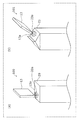
- FIG. 4 is a diagram illustrating a marking device 101 according to the first modification of the first embodiment.
- FIG. 4A shows the relative positional relationship between the work 20 and the dispenser 13 in the first embodiment.
- FIG. 4B shows a relative positional relationship between the work 23 and the dispenser 13 in the first modification.
- the dispenser 13 of the marking device 101 is focused on in the drawing, and the other parts are omitted.
- the surface to be marked of the work 20 in the first embodiment is the top surface of the cap 20a of the container filled with the liquid beverage, and the work 20 of the conveyor 21 is placed thereon. It is a surface parallel to the transport surface.
- the dispenser 13 is configured such that the axial direction of the nozzle 13a substantially coincides with the vertical direction of the surface to be marked. Therefore, the axial direction of the nozzle 13a is in a relationship that substantially coincides with the vertical direction even on the conveyance surface of the work 20.
- the marking surface of the work 20 is a surface parallel to the transport surface, and thus the configuration in which the resin material is discharged in the direction following the gravity direction is most suitable because the accuracy of the landing position of the resin material is high. Because it is a simple configuration.
- the marking surface of the work 23 in this modification shown in FIG. 4B is common to the first embodiment described above in that it is the top surface of the cap 23a of the container filled with the liquid beverage.
- the top surface is different from that of the first embodiment in that the top surface is a surface that forms a predetermined angle with the transport surface on which the work 23 of the conveyor 21 is placed.
- the marking surface is a surface to which the resin material is landed on a surface perpendicular to the traveling direction of the discharged resin material.
- the dispenser 13 in this modification is arranged so that the traveling direction of the resin material is inclined with respect to the marking surface.
- the axial direction of the nozzle 13a and the vertical direction of the surface to be marked are substantially aligned.
- the traveling direction of the resin material discharged from the nozzle 13a substantially coincides with the axial direction of the nozzle 13a, and enters the marking surface from the vertical direction. Therefore, it is possible to realize the marking device 101 which has a high precision of the landing position even on the work 23 having the surface to be marked which is inclined with respect to the transport surface and which can accurately mark the dot-shaped projection.
- the dispenser 13 and the nozzle 13a may be tilted so that the axial direction of the nozzle 13a is tilted with respect to the transport surface.
- the main body 10 and the dispenser 13 may be tilted so that the axial direction of the nozzle 13a is tilted with respect to the transport surface.
- the marking device 101 and the main body 10 may be tilted so that the axial direction of the nozzle 13a is tilted with respect to the transport surface.
- the nozzle 13a may eject the resin material in the direction of gravity, and the conveyance surface may be inclined with respect to the horizontal plane orthogonal to the direction of gravity, so that the inclination of the surface to be marked may be relaxed.
- Such a configuration may be realized by inclining the conveyor 21 or the vertical belt 16.
- the workpiece 23 conveyed by the conveyor 21 has the marking surface on which the projection is formed inclined with respect to the conveying surface on which the workpiece 23 is placed.
- the dispenser 13 is arranged so as to be inclined with respect to the transport surface so that the vertical direction of the surface to be marked and the axial direction of the nozzle 13a through which the resin material is discharged match.
- the marking device 101 can discharge the resin material to the work 23 having the surface to be marked which is inclined with respect to the transport surface by using the dispenser 13 which is also inclined. Therefore, the marking device 101 has high accuracy in the landing position and can accurately mark the dot-shaped projection.
- the marking device 101 according to the present modification is different from the above-described first embodiment in that the dispenser 13 inclines corresponding to the inclination of the surface to be marked of the work 23, so that more various works can be marked with dot-like protrusions. be able to.
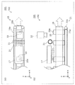
- FIG. 5 is a schematic configuration diagram illustrating a marking device 102 according to the second modification of the first embodiment.
- FIG. 5A is a top view of the production line 201 including the marking device 102.
- FIG. 5B is a side view of the production line 201 including the marking device 102. Note that, as in FIG. 1, in FIG. 5A and FIG. 5B, a hidden part of the work 20 is indicated by a broken line. The upstream side (x-axis minus side) of the curing section 17 of the conveyor 21 of the production line 201 is omitted. Further, in this modification, the protrusion formed by curing the resin material is inspected. Therefore, a product on the production line 201 until the inspection is completed is described as a work 20, and a product in a state in which the inspection is completed and determined to be ready for shipment is described as a product with a protrusion.
- the present modification further includes a loading device that applies a load to the protrusion marked on the work 20, and an observation device that observes the protrusion after the load is applied by the loading device.
- the marking device 102 including an inspection unit that inspects whether or not the protrusion has a predetermined drop resistance will be described.
- FIG. 5 shows the further downstream (x-axis plus side) of the curing section 17 in the marking device 102 installed on the production line 201.
- a load roller 31 an example of a load device
- an observation camera 32 an example of an observation device
- the load roller 31 and the observation camera 32 configure an inspection unit that inspects whether or not the projection on the work 20 has a predetermined drop resistance.
- the load roller 31 and the observation camera 32 will be further described below in detail.
- the load roller 31 has a motor, a cylindrical roller that rotates around the rotation axis of the motor when the motor is driven, and a brush that includes bristles formed along the radial direction of the roller.
- the motor rotates the brushed roller at a predetermined speed and force. In the brush rotated together with the roller, the bristles contact the protrusions marked on the work 20.
- the load roller 31 is set with a predetermined load applied to the protrusion by the force (torque) of the motor and the hardness of the hair-like member.
- the predetermined load is a value that virtually sets the load that can be applied to the protrusion when the produced product with the protrusion is handled, and the load due to vibration during transportation of the product with the protrusion is set. ..
- a plurality of load rollers 31 may be provided so as to apply forces in a plurality of directions to the protrusion.
- the load roller 31 may be replaced with a device that applies a load that leads to dropout of an arbitrary projection, in accordance with various loads that can be applied to the projection.
- the observation camera 32 is a camera that acquires an image for determining whether or not the protrusion marked on the work 20 is formed according to the marking pattern of the protrusion.
- the observation camera 32 is further provided with a processing device including a processor, a memory, and an application.
- the observation camera 32 analyzes the acquired image by the processing device to determine whether or not the protrusion marked on the work 20 has fallen off.
- observation camera 32 may have a function of detecting not only the protrusion of the load roller 31 but also the defect of formation of the protrusion due to ejection failure of the dispenser 13.
- the observation camera 32 further outputs an alarm signal for issuing an alarm to a manager of the production line 201 (for example, a person in charge of manufacturing a product with protrusions) when an image in which it is determined that the protrusions are missing is acquired. It may be configured to. Further, the observation camera 32 may be configured to output a stop signal for stopping the production line 201 when acquiring the image in which it is determined that the protrusion has fallen off.
- a manager of the production line 201 for example, a person in charge of manufacturing a product with protrusions
- the marking device 102 further observes the load roller 31 that applies a load to the protrusion marked on the work 20, and the protrusion after the load is applied by the load roller 31.
- the marking device 102 determines whether or not the marked protrusions are normally formed, and guarantees that the dot-shaped protrusions can be accurately marked on each of a plurality of mass-produced products with protrusions. it can.
- This modification can be applied not only to the first embodiment but also to the above-described modification 1.
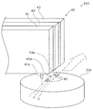
- FIG. 6 is an enlarged perspective view of the dispenser 40 for explaining the marking device 103 according to the second embodiment.
- the difference from the dispenser 13 in the first embodiment will be mainly described, and the description of the other substantially the same components will be omitted.
- the marking device 103 according to the present embodiment is different from the marking device 100 according to the first embodiment in that a plurality of dispensers 40 are provided.
- FIG. 6 shows a plurality of dispensers 40 and a cap 20a of a container filled with a liquid beverage having a surface to be marked on the top surface.
- a three-dimensional shape 45 ejected from a plurality of dispensers 40 is formed on the top surface of the cap 20a.
- the plurality of dispensers 40 are configured by three dispensers 41, 42, and 43 in this description, but the present invention is not limited to this.
- the number of the plurality of dispensers 40 may be four, five, or six.
- the number of the plurality of dispensers 40 is appropriately set in accordance with the marking pattern and in consideration of various restrictions such as the size of the surface to be marked.
- each of the dispensers 41 to 43 has nozzles 41a to 43a for discharging a resin material.
- a discharge command is transmitted from the control unit 14 to each of the plurality of dispensers 40, and each of the dispensers 41 to 43 can independently discharge the resin material. More specifically, the dispenser 41 receives a discharge command from the control unit 14 to cause the dispenser 41 to discharge the resin material.
- the dispenser 42 also receives, from the control unit 14, a discharge command for causing the dispenser 42 to discharge the resin material.
- the dispenser 43 also receives, from the control unit 14, a discharge command for causing the dispenser 43 to discharge the resin material.
- Each of the dispensers 41 to 43 of the plurality of dispensers 40 is assigned a row for discharging the resin material on the marking pattern. That is, the dispensers 41 to 43 are fixed at positions in the direction orthogonal to the moving direction of the work 20, and the discharge of the resin material is assigned to the respective positions in the orthogonal direction. Therefore, the nozzles 41a to 43a are arranged so as to be offset from each other in the direction orthogonal to the movement direction of the work 20, and are assigned to the dispensers 41 to 43 in the first row to the third row on the marking pattern.
- the resin material is discharged according to the row pattern designated in the row iii (two-dot chain line in FIG. 6).
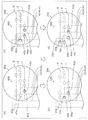
- FIG. 7 is a diagram for explaining the operation of the marking device 103 according to the second embodiment.
- FIG. 7 shows a plurality of dispensers 40 and a marked surface of the cap 20a, and a marking pattern 400 corresponding to the marked surface is virtually overlapped.
- the matrix of the protrusions shown in the marking pattern 400 is assigned to each of the three dispensers in one row (first row i to third row iii), the ejection of the resin material is performed for each droplet. It is shown separated by. Further, in FIG. 7, the movement of the marking pattern 400 (that is, the movement of the marked surface of the work 20) is the movement from the right side to the left side of the drawing.
- FIG. 7A shows the operation of the plurality of dispensers 40 in the first droplet ejection.
- FIG. 7B shows the operation of the plurality of dispensers 40 in the second droplet ejection.
- FIG. 7C shows the operation of the plurality of dispensers 40 in the third droplet ejection.
- FIG. 7D shows the operation of the plurality of dispensers 40 in the fourth droplet ejection.
- the work 20 further moves, and the ejection timing shown in the first row i and the position of the nozzle 41a of the dispenser 41 match. Therefore, the dispenser 41 discharges the resin material to form a three-dimensional shape 45c of the resin material for the third droplet ejection on the surface to be marked.
- FIG. 7D the work 20 further moves, and the ejection timing shown in the third row and the position of the nozzle 43a of the dispenser 43 match. Therefore, the dispenser 43 discharges the resin material to form a three-dimensional shape 45d of the resin material for the fourth droplet ejection on the surface to be marked.
- the first droplet ejection shown in (a) of FIG. 7 is performed based on the time when the position of the work piece 20 detected by the detection unit 12 coincides with a preset predetermined position. .. Further, the second to fourth droplets shown in FIGS. 7B to 7D are based on the pulse transmitted from the encoder 11 with the position of the workpiece 20 at the time of the first droplet being the starting point. It is managed by the moving distance of 20.
- the configuration of the marking device 103 with three dispensers can be particularly preferably used for marking the protrusions in a matrix of three rows. That is, the marking device 103 is suitable for use in braille marking such as 6-dot braille, which is represented by a matrix of protrusions in 3 rows and 2 columns.
- the marking device 103 is not limited to the Braille marking described above, but can be used for any purpose of marking a dot-shaped protrusion such as a convex mark.
- the marking device 103 further includes the plurality of dispensers 40, and each of the plurality of dispensers 40 includes the resin material in the top view seen from the direction in which the work 20 and the conveyor 21 overlap.
- the ejecting nozzles 41a to 43a are arranged so as to be offset from each other in a direction orthogonal to the conveying direction of the conveyor 21, and the control unit 14 transmits an ejecting command to each of the plurality of dispensers 40.
- the marking device 103 uses a finer marking. Can be adapted to patterns. Therefore, the marking device 103 is incorporated in the production line 200 (in-line), and can mark a plurality of dot-shaped projections on demand on the conveyed work 20 without lowering productivity.
- each function of the constituent elements of the marking device may be distributed to a plurality of parts of the marking device in any way.
- a cooling unit may be provided to help maintain the three-dimensional shape until the resin material is further cured.
- This may be realized by a configuration in which the ambient temperature of the work 20 is lowered on the downstream side of the position corresponding to the dispenser 13 in the production line 200.
- the three-dimensional shape 45 made of the resin material discharged onto the work 20 may be blown with cool air to cool the three-dimensional shape 45 made of the resin material.
- the surface to be marked and the axis of the nozzle 13a of the dispenser 13 are orthogonal to each other.
- the positional relationship between the surface to be marked and the axial direction of the nozzle 13a may not be vertical. Good.
- control unit 14 has described the configuration for transmitting the discharge command to the dispenser 13.
- the control unit 14 may send the timing chart to the dispenser 13.
- the dispenser 13 may perform control according to the received timing chart to eject the resin material at the ejection timing and not eject the resin material at the non-ejection timing.
- timing chart is updated as the master clock changes, it is necessary to send the updated timing chart.
- the transmission of such a timing chart may be configured such that the latest timing chart at that time is transmitted every time the timing chart is updated, every preset period, or every ejection of one droplet.
- the marking surface is a metal or the like having a sufficiently high melting point
- molten metal, molten glass, or the like may be used as the droplet.
- either one or both of the encoder 11 and the detection unit 12 may not be provided.
- the marking pattern 400 may be included in the marking device in advance.
- the marking device can be realized without the acquisition unit 15.
- the dispensers may be arranged at a plurality of locations on the production line 200, and a three-dimensional shape made of a resin material may be formed on each of the marking surfaces. More specifically, the configuration in which the plurality of dispensers 40 are divided into three marking patterns and assigned to the respective dispensers 41 to 43 has been described in the second embodiment. On the other hand, each of the plurality of dispensers may discharge the resin material according to an individual marking pattern.
- the height of the protrusion is at least 0.5 mm has been described, but since the height of the protrusion can be controlled by the discharge amount of the resin material by the dispenser 13, even if a protrusion having an arbitrary height is marked. Good.
- the resin material used in the embodiment is an ultraviolet light curable resin, and the resin material is cured by the curing unit 17 that radiates ultraviolet light to form protrusions.
- the resin material may be made of a curable resin by thermosetting, infrared light curing, or radiant light curing, and the curing portion may be configured to include a heat source and a light source necessary for curing each resin.
- the marking device and the like in the present invention can form protrusions on a work in-line, and are useful, for example, in applications such as providing tactilely readable descriptions to products.
Landscapes
- Coating Apparatus (AREA)
- Application Of Or Painting With Fluid Materials (AREA)
Abstract
L'invention concerne un dispositif de marquage (100), qui marque des parties en saillie sur chaque pièce d'une pluralité de pièces (20) transportées en continu par un transporteur (21), comprenant un distributeur de type à jet (13) et une unité de commande (14) qui divise une pluralité de périodes en périodes de décharge pendant lesquelles un matériau en résine est déchargé et des périodes de non-décharge pendant lesquelles le matériau en résine n'est pas déchargé et qui transmet une instruction de décharge pendant les périodes de décharge sur la base d'un motif de marquage, le distributeur (13) déchargeant le matériau en résine sur la base de l'instruction de décharge reçue.
Priority Applications (1)
| Application Number | Priority Date | Filing Date | Title |
|---|---|---|---|
| JP2020566128A JP7012886B2 (ja) | 2019-01-18 | 2019-11-22 | マーキング装置 |
Applications Claiming Priority (2)
| Application Number | Priority Date | Filing Date | Title |
|---|---|---|---|
| JP2019-007241 | 2019-01-18 | ||
| JP2019007241 | 2019-01-18 |
Publications (1)
| Publication Number | Publication Date |
|---|---|
| WO2020149009A1 true WO2020149009A1 (fr) | 2020-07-23 |
Family
ID=71614289
Family Applications (1)
| Application Number | Title | Priority Date | Filing Date |
|---|---|---|---|
| PCT/JP2019/045773 Ceased WO2020149009A1 (fr) | 2019-01-18 | 2019-11-22 | Dispositif de marquage et procédé de fabrication d'un produit doté de parties en saillie |
Country Status (2)
| Country | Link |
|---|---|
| JP (1) | JP7012886B2 (fr) |
| WO (1) | WO2020149009A1 (fr) |
Cited By (2)
| Publication number | Priority date | Publication date | Assignee | Title |
|---|---|---|---|---|
| US20240009695A1 (en) * | 2022-07-07 | 2024-01-11 | Corey Albert Graves | Personalized marking apparatus, system and method for container identification |
| TWI855542B (zh) * | 2022-02-14 | 2024-09-11 | 瑞士商巴柏斯特麥克斯合資公司 | 檢測盲文之檢查系統及其方法 |
Families Citing this family (1)
| Publication number | Priority date | Publication date | Assignee | Title |
|---|---|---|---|---|
| KR102719503B1 (ko) * | 2024-03-14 | 2024-10-18 | 주식회사 되살림패키지 | 잉크 공급 헤드 및 이를 구비하는 점자 인쇄 장치 |
Citations (3)
| Publication number | Priority date | Publication date | Assignee | Title |
|---|---|---|---|---|
| JPH05143767A (ja) * | 1991-11-16 | 1993-06-11 | Goro Tsuchiya | 2次元コード装置 |
| JP2009039658A (ja) * | 2007-08-09 | 2009-02-26 | Seiko Epson Corp | 液状体の吐出制御方法、液滴吐出装置 |
| JP2013095116A (ja) * | 2011-11-04 | 2013-05-20 | Musashi Eng Co Ltd | 点字形成方法および点字塗布装置 |
Family Cites Families (1)
| Publication number | Priority date | Publication date | Assignee | Title |
|---|---|---|---|---|
| JPH09319295A (ja) * | 1996-05-28 | 1997-12-12 | Puroka Corp:Kk | 点字表示板作成方法および装置 |
-
2019
- 2019-11-22 JP JP2020566128A patent/JP7012886B2/ja active Active
- 2019-11-22 WO PCT/JP2019/045773 patent/WO2020149009A1/fr not_active Ceased
Patent Citations (3)
| Publication number | Priority date | Publication date | Assignee | Title |
|---|---|---|---|---|
| JPH05143767A (ja) * | 1991-11-16 | 1993-06-11 | Goro Tsuchiya | 2次元コード装置 |
| JP2009039658A (ja) * | 2007-08-09 | 2009-02-26 | Seiko Epson Corp | 液状体の吐出制御方法、液滴吐出装置 |
| JP2013095116A (ja) * | 2011-11-04 | 2013-05-20 | Musashi Eng Co Ltd | 点字形成方法および点字塗布装置 |
Cited By (3)
| Publication number | Priority date | Publication date | Assignee | Title |
|---|---|---|---|---|
| TWI855542B (zh) * | 2022-02-14 | 2024-09-11 | 瑞士商巴柏斯特麥克斯合資公司 | 檢測盲文之檢查系統及其方法 |
| US20240009695A1 (en) * | 2022-07-07 | 2024-01-11 | Corey Albert Graves | Personalized marking apparatus, system and method for container identification |
| US12485449B2 (en) * | 2022-07-07 | 2025-12-02 | Corey Albert Graves | Personalized marking apparatus, system and method for container identification |
Also Published As
| Publication number | Publication date |
|---|---|
| JPWO2020149009A1 (ja) | 2021-09-30 |
| JP7012886B2 (ja) | 2022-01-28 |
Similar Documents
| Publication | Publication Date | Title |
|---|---|---|
| JP7012886B2 (ja) | マーキング装置 | |
| KR100870451B1 (ko) | 액적 토출 장치 및 식별 코드 | |
| CN107115999B (zh) | 用于将粘性介质喷射在工件上的方法和设备 | |
| CN101282842B (zh) | 用于将物质小滴受控地定位到基底上的喷墨装置和方法 | |
| JP5073501B2 (ja) | プラスチック容器上にデジタル画像を印刷する方法 | |
| JP5956738B2 (ja) | 点字形成方法および点字塗布装置 | |
| JPWO2018062463A1 (ja) | 作業装置および作業方法 | |
| US20130307890A1 (en) | Ink jet printer and method for depositing a protective layer on a substrate | |
| TWI548531B (zh) | 一種噴墨印表機用凹凸面定位及列印方法 | |
| US20100129542A1 (en) | Verfahren und vorrichtung zum beschichten zumindest eines teiles eines substrates | |
| US11458727B2 (en) | Printer | |
| KR20120103450A (ko) | 인쇄 장치 | |
| TW202138204A (zh) | 印刷裝置 | |
| CN206718471U (zh) | 一种高效3d打印机 | |
| KR20220010395A (ko) | 홀의 내측면 또는 기판의 외측면을 프린팅하는 프린팅 장치 | |
| JP5712730B2 (ja) | インクジェット描画装置 | |
| JP2016182695A (ja) | 液体吐出装置及び液体吐出方法 | |
| CN108394197A (zh) | 喷墨印刷方法 | |
| US10654290B2 (en) | Liquid dispensing amount control apparatus and control method thereof and inkjet printing apparatus | |
| JP6414888B2 (ja) | 液滴吐出装置、着滴精度検査装置、及び、着滴精度検査方法 | |
| KR102852397B1 (ko) | 복수의 패키징 용기가 정렬되어 배치되는 베이스를 이동시키는 방식에 의해 복수의 패키징 용기에 신속하고 정밀하게 프린팅을 수행하는 디지털 프린터기 | |
| JP2010280195A (ja) | インクミストによる液体吐出装置の汚染防止方法、および液体吐出装置 | |
| JP2023045796A (ja) | 立体物印刷装置 | |
| JP2012213739A (ja) | 液体噴射装置 | |
| KR20260024198A (ko) | 잉크 토출 장치 및 잉크 토출 방법 |
Legal Events
| Date | Code | Title | Description |
|---|---|---|---|
| 121 | Ep: the epo has been informed by wipo that ep was designated in this application |
Ref document number: 19910292 Country of ref document: EP Kind code of ref document: A1 |
|
| ENP | Entry into the national phase |
Ref document number: 2020566128 Country of ref document: JP Kind code of ref document: A |
|
| NENP | Non-entry into the national phase |
Ref country code: DE |
|
| 122 | Ep: pct application non-entry in european phase |
Ref document number: 19910292 Country of ref document: EP Kind code of ref document: A1 |