WO2020152731A1 - 燃料電池セル及び燃料電池モジュール - Google Patents
燃料電池セル及び燃料電池モジュール Download PDFInfo
- Publication number
- WO2020152731A1 WO2020152731A1 PCT/JP2019/001578 JP2019001578W WO2020152731A1 WO 2020152731 A1 WO2020152731 A1 WO 2020152731A1 JP 2019001578 W JP2019001578 W JP 2019001578W WO 2020152731 A1 WO2020152731 A1 WO 2020152731A1
- Authority
- WO
- WIPO (PCT)
- Prior art keywords
- fuel cell
- solid electrolyte
- oxygen ion
- layer
- cathode electrode
- Prior art date
- Legal status (The legal status is an assumption and is not a legal conclusion. Google has not performed a legal analysis and makes no representation as to the accuracy of the status listed.)
- Ceased
Links
Images








Classifications
-
- H—ELECTRICITY
- H01—ELECTRIC ELEMENTS
- H01M—PROCESSES OR MEANS, e.g. BATTERIES, FOR THE DIRECT CONVERSION OF CHEMICAL ENERGY INTO ELECTRICAL ENERGY
- H01M8/00—Fuel cells; Manufacture thereof
- H01M8/10—Fuel cells with solid electrolytes
- H01M8/12—Fuel cells with solid electrolytes operating at high temperature, e.g. with stabilised ZrO2 electrolyte
- H01M8/1286—Fuel cells applied on a support, e.g. miniature fuel cells deposited on silica supports
-
- H—ELECTRICITY
- H01—ELECTRIC ELEMENTS
- H01M—PROCESSES OR MEANS, e.g. BATTERIES, FOR THE DIRECT CONVERSION OF CHEMICAL ENERGY INTO ELECTRICAL ENERGY
- H01M4/00—Electrodes
- H01M4/86—Inert electrodes with catalytic activity, e.g. for fuel cells
- H01M4/8605—Porous electrodes
- H01M4/8621—Porous electrodes containing only metallic or ceramic material, e.g. made by sintering or sputtering
-
- H—ELECTRICITY
- H01—ELECTRIC ELEMENTS
- H01M—PROCESSES OR MEANS, e.g. BATTERIES, FOR THE DIRECT CONVERSION OF CHEMICAL ENERGY INTO ELECTRICAL ENERGY
- H01M8/00—Fuel cells; Manufacture thereof
- H01M8/10—Fuel cells with solid electrolytes
- H01M8/12—Fuel cells with solid electrolytes operating at high temperature, e.g. with stabilised ZrO2 electrolyte
- H01M8/1213—Fuel cells with solid electrolytes operating at high temperature, e.g. with stabilised ZrO2 electrolyte characterised by the electrode/electrolyte combination or the supporting material
-
- H—ELECTRICITY
- H01—ELECTRIC ELEMENTS
- H01M—PROCESSES OR MEANS, e.g. BATTERIES, FOR THE DIRECT CONVERSION OF CHEMICAL ENERGY INTO ELECTRICAL ENERGY
- H01M8/00—Fuel cells; Manufacture thereof
- H01M8/10—Fuel cells with solid electrolytes
- H01M8/12—Fuel cells with solid electrolytes operating at high temperature, e.g. with stabilised ZrO2 electrolyte
- H01M8/124—Fuel cells with solid electrolytes operating at high temperature, e.g. with stabilised ZrO2 electrolyte characterised by the process of manufacturing or by the material of the electrolyte
- H01M8/1246—Fuel cells with solid electrolytes operating at high temperature, e.g. with stabilised ZrO2 electrolyte characterised by the process of manufacturing or by the material of the electrolyte the electrolyte consisting of oxides
- H01M8/1253—Fuel cells with solid electrolytes operating at high temperature, e.g. with stabilised ZrO2 electrolyte characterised by the process of manufacturing or by the material of the electrolyte the electrolyte consisting of oxides the electrolyte containing zirconium oxide
-
- H—ELECTRICITY
- H01—ELECTRIC ELEMENTS
- H01M—PROCESSES OR MEANS, e.g. BATTERIES, FOR THE DIRECT CONVERSION OF CHEMICAL ENERGY INTO ELECTRICAL ENERGY
- H01M8/00—Fuel cells; Manufacture thereof
- H01M8/10—Fuel cells with solid electrolytes
- H01M8/12—Fuel cells with solid electrolytes operating at high temperature, e.g. with stabilised ZrO2 electrolyte
- H01M8/124—Fuel cells with solid electrolytes operating at high temperature, e.g. with stabilised ZrO2 electrolyte characterised by the process of manufacturing or by the material of the electrolyte
- H01M8/1246—Fuel cells with solid electrolytes operating at high temperature, e.g. with stabilised ZrO2 electrolyte characterised by the process of manufacturing or by the material of the electrolyte the electrolyte consisting of oxides
- H01M8/126—Fuel cells with solid electrolytes operating at high temperature, e.g. with stabilised ZrO2 electrolyte characterised by the process of manufacturing or by the material of the electrolyte the electrolyte consisting of oxides the electrolyte containing cerium oxide
-
- H—ELECTRICITY
- H01—ELECTRIC ELEMENTS
- H01M—PROCESSES OR MEANS, e.g. BATTERIES, FOR THE DIRECT CONVERSION OF CHEMICAL ENERGY INTO ELECTRICAL ENERGY
- H01M8/00—Fuel cells; Manufacture thereof
- H01M8/10—Fuel cells with solid electrolytes
- H01M8/12—Fuel cells with solid electrolytes operating at high temperature, e.g. with stabilised ZrO2 electrolyte
- H01M2008/1293—Fuel cells with solid oxide electrolytes
-
- H—ELECTRICITY
- H01—ELECTRIC ELEMENTS
- H01M—PROCESSES OR MEANS, e.g. BATTERIES, FOR THE DIRECT CONVERSION OF CHEMICAL ENERGY INTO ELECTRICAL ENERGY
- H01M2300/00—Electrolytes
- H01M2300/0017—Non-aqueous electrolytes
- H01M2300/0065—Solid electrolytes
- H01M2300/0068—Solid electrolytes inorganic
- H01M2300/0071—Oxides
- H01M2300/0074—Ion conductive at high temperature
-
- H—ELECTRICITY
- H01—ELECTRIC ELEMENTS
- H01M—PROCESSES OR MEANS, e.g. BATTERIES, FOR THE DIRECT CONVERSION OF CHEMICAL ENERGY INTO ELECTRICAL ENERGY
- H01M2300/00—Electrolytes
- H01M2300/0017—Non-aqueous electrolytes
- H01M2300/0065—Solid electrolytes
- H01M2300/0068—Solid electrolytes inorganic
- H01M2300/0071—Oxides
- H01M2300/0074—Ion conductive at high temperature
- H01M2300/0077—Ion conductive at high temperature based on zirconium oxide
-
- Y—GENERAL TAGGING OF NEW TECHNOLOGICAL DEVELOPMENTS; GENERAL TAGGING OF CROSS-SECTIONAL TECHNOLOGIES SPANNING OVER SEVERAL SECTIONS OF THE IPC; TECHNICAL SUBJECTS COVERED BY FORMER USPC CROSS-REFERENCE ART COLLECTIONS [XRACs] AND DIGESTS
- Y02—TECHNOLOGIES OR APPLICATIONS FOR MITIGATION OR ADAPTATION AGAINST CLIMATE CHANGE
- Y02E—REDUCTION OF GREENHOUSE GAS [GHG] EMISSIONS, RELATED TO ENERGY GENERATION, TRANSMISSION OR DISTRIBUTION
- Y02E60/00—Enabling technologies; Technologies with a potential or indirect contribution to GHG emissions mitigation
- Y02E60/30—Hydrogen technology
- Y02E60/50—Fuel cells
-
- Y—GENERAL TAGGING OF NEW TECHNOLOGICAL DEVELOPMENTS; GENERAL TAGGING OF CROSS-SECTIONAL TECHNOLOGIES SPANNING OVER SEVERAL SECTIONS OF THE IPC; TECHNICAL SUBJECTS COVERED BY FORMER USPC CROSS-REFERENCE ART COLLECTIONS [XRACs] AND DIGESTS
- Y02—TECHNOLOGIES OR APPLICATIONS FOR MITIGATION OR ADAPTATION AGAINST CLIMATE CHANGE
- Y02P—CLIMATE CHANGE MITIGATION TECHNOLOGIES IN THE PRODUCTION OR PROCESSING OF GOODS
- Y02P70/00—Climate change mitigation technologies in the production process for final industrial or consumer products
- Y02P70/50—Manufacturing or production processes characterised by the final manufactured product
Definitions
- the present invention relates to a fuel cell and a fuel cell module.
- Non-Patent Document 1 describes a cell technology for forming an anode layer, a solid electrolyte layer and a cathode layer of a fuel cell membrane by a thin film deposition process.
- ionic conductivity can be improved and power generation efficiency can be increased.
- the ionic conductivity of the solid electrolyte exhibits activation-type temperature dependence. Therefore, the ionic conductivity is high at high temperature and low at low temperature.
- thinning the solid electrolyte a sufficiently large ionic conductivity can be obtained even at a low temperature, and a practical power generation efficiency can be realized.
- YSZ Yttria Stabilized Zirconia
- zirconia doped with yttria is often used. This is because it has the advantages of excellent chemical stability and less current due to electrons and holes that cause internal leakage current of the fuel cell.
- Patent Document 1 discloses a fuel cell technology using a proton conductor such as BaCeO 3 or SrCeO 3 as a solid electrolyte. Since these solid electrolytes have high proton conductivity, they are advantageous in improving power generation efficiency. However, it is known that this solid electrolyte reacts when it comes into contact with carbon dioxide gas, and carbonates such as BaCO 3 and SrCO 3 are produced, thereby significantly deteriorating the performance of the fuel cell. In Patent Document 1, assuming that carbon dioxide gas is contained in the reformed gas of the fuel, a palladium (Pd) film that allows hydrogen as a fuel to pass through but does not allow carbon dioxide to pass through is formed on the surface of the solid electrolyte membrane. The technique for forming the same is described.
- a palladium (Pd) film that allows hydrogen as a fuel to pass through but does not allow carbon dioxide to pass through is formed on the surface of the solid electrolyte membrane. The technique for forming the same is described.
- Patent Document 2 describes a fuel cell technique in which BaZrO 3 , SrZrO 3, or the like, which is a proton conductor, is used for a solid electrolyte layer on a hydrogen-permeable anode (anode) substrate.
- the main charge carriers of BaZrO 3 and SrZrO 3 are protons, but oxygen ions (O 2 ⁇ ) also conduct.
- oxygen ions generated from oxygen gas in the atmosphere on the cathode side conduct through the solid electrolyte layer and reach the boundary between the hydrogen-permeable anode substrate and the solid electrolyte layer, they react with hydrogen to produce water, and the anode substrate And the problem of deteriorating the adhesiveness of the solid electrolyte layer.
- Patent Document 3 in a fuel cell using an oxygen ion conductor Bi 2 O 3 , a proton block layer and an electron current block are provided in order to suppress current due to charge carriers other than oxygen ions, that is, protons, electrons and holes.
- a technique for providing a layer and a hole current blocking layer is described.
- Patent Document 4 describes a technique related to a single-chamber fuel cell that supplies a gas in which oxygen and fuel are mixed to both an anode electrode and a cathode electrode. It is possible to simplify the structure of the fuel cell compared to supplying the fuel gas and the oxygen gas to the anode electrode side and the cathode electrode side, respectively.
- Doped zirconia such as YSZ is known as an oxygen ion conductor, but there is a problem that the ionic conductivity is not very high.
- the present inventors have found for the first time that when a thin film is formed to improve the power generation efficiency of doped zirconia, proton conduction exceeding oxygen ion conduction occurs.
- the thin film zirconia doped in the solid electrolyte layer of the fuel cell is used, both proton conduction and oxygen ion conduction occur, so that water is generated in the solid electrolyte. If the generated water is not immediately removed into the atmosphere, the electromotive force will drop.
- the present invention uses a fuel cell having doped zirconia as a solid electrolyte layer, which exhibits proton conductivity by thinning, and prevents oxygen ions from conducting in the solid electrolyte layer in the fuel cell.
- the purpose is to suppress the generation of water inside.
- the present invention prevents oxygen ions generated at the cathode from conducting in the solid electrolyte and also suppresses the generation of water in the solid electrolyte. To aim.
- the present inventors have found that the oxygen ion conductivity between a cathode electrode of a solid oxide fuel cell (SOFC) exposed to oxygen gas and a solid electrolyte layer formed of doped thin film zirconia or doped thin film ceria. It was found that the above problems can be solved by forming an oxygen ion blocking layer lower than the solid electrolyte layer, and completed the invention.
- SOFC solid oxide fuel cell
- the fuel cell of the present invention comprises a cathode electrode, an anode electrode, and polycrystalline zirconia having proton conductivity, which is disposed between the cathode electrode and the anode electrode and is doped with divalent or trivalent positive ions. Or a solid electrolyte layer made of polycrystalline ceria, wherein the cathode electrode and the solid electrolyte layer are laminated via a first oxygen ion blocking layer.
- an oxygen ion blocking layer can be formed at the boundary between both electrodes and the solid electrolyte layer so that oxygen ions do not diffuse into the solid electrolyte layer formed of the doped thin film zirconia or the doped thin film ceria.
- FIG. 6A is a schematic diagram showing movements of oxygen ions and protons in the thin film process type SOFC of the first embodiment.
- (B) is a schematic diagram showing the movement of oxygen ions and protons in a conventional thin film process type SOFC. It is a graph which shows the film thickness of the 1st oxygen ion blocking layer in 1st Embodiment, and the relationship of proton conductivity.
- It is a schematic diagram showing an example of composition of a thin film process type SOFC of a 2nd embodiment.
- the X direction, the Y direction, and the Z direction are used as directions for explanation.
- the X direction and the Y direction are orthogonal to each other and constitute a horizontal plane, and the Z direction is a direction perpendicular to the horizontal plane.
- hatching may be omitted even in a sectional view in order to make the drawings easy to see. Further, even a plan view may be hatched to make the drawing easier to see.
- the size of each part does not correspond to the actual device, and in order to make the drawing easy to understand, a specific part may be displayed relatively large. Even when the cross-sectional view and the plan view correspond to each other, a specific portion may be displayed relatively large in order to make the drawing easy to understand.
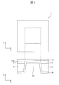
- FIG. 1 is a schematic diagram showing an example of the configuration of a conventional thin film process fuel cell.
- the fuel cell 1 of FIG. 1 includes an anode electrode 20, a solid electrolyte layer 100, and a cathode electrode 10.
- the mechanical strength of the fuel cell membrane electrode assembly is weakened. However, by supporting the assembly on the substrate 2 as shown in FIG. , Can supplement the mechanical strength.
- the insulating film 3 is provided between the substrate 2 and the solid electrolyte layer 100.
- An opening 50 is provided in the center of the substrate 2, and the anode electrode 20 and the solid electrolyte layer 100 are in contact with each other in the opening 50.
- the substrate for example, silicon, ceramic, glass, SUS or the like can be used.
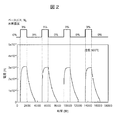
- Fig. 2 is data showing the atmosphere dependency of the current flowing through YSZ. Specifically, it is a graph showing the result of measuring the current due to hydrogen ion conduction in the thin film zirconia doped with yttria. Platinum was used for the electrodes, and measurement was performed with a zirconia thin film having a film thickness of 500 nm doped with 8% yttria. In the experiment, a platinum electrode was formed on the surface of YSZ, and the hydrogen concentration in the atmosphere was changed while a constant voltage was applied between the electrodes. The base gas is nitrogen. It was observed that the current increased every time the hydrogen concentration was changed from 0% to 3%. This result indicates that a current is flowing due to proton conduction. The current seen in FIG.
- the solid electrolyte which is an oxygen ion conductor in bulk, exhibits proton conductivity due to the thin film formation. Therefore, the solid electrolyte is used for the solid electrolyte layer to fabricate the fuel cell according to the first embodiment. did.
- polycrystalline zirconia in which a divalent or trivalent positive ion is doped in a zirconium site, or polycrystalline ceria in which a divalent or trivalent positive ion is doped in a cerium site is a chemical that shows proton conductivity by thinning and does not decompose even when exposed to carbon dioxide as compared with (BaY)ZrO 3 , (SrY)ZrO 3 , (BaY)CeO 3 , and (SrY)CeO 3. Excellent stability.
- polycrystalline zirconia obtained by doping a zirconium site with divalent or trivalent positive ions has a small amount of electron current and hole current, which are internal leak currents of the fuel cell, the solid electrolyte layer is thinned to improve power generation efficiency. be able to.
- Patent Document 2 discloses (BaY)CeO 3 or (SrY). A method is described in which CeO 3 is used for the solid electrolyte layer and oxygen ions that are slightly conducted by these solid electrolyte layers are blocked by the intervening layer.
- the present embodiment it is known as an oxygen ion conductor in a bulk state, and compared with other metal oxides, an electron current that becomes an internal leak of the battery, and a doped zirconia having a very small hole current in the solid electrolyte layer.
- an oxygen ion conductor in a bulk state, and compared with other metal oxides, an electron current that becomes an internal leak of the battery, and a doped zirconia having a very small hole current in the solid electrolyte layer.
- doped zirconia other ionic conductors have been conventionally investigated, because the oxygen ionic conductivity of doped zirconia was insufficient to improve power generation performance, As a result of the study by the present inventors, it was found that the doped zirconia thinned has a proton conductivity higher than that of oxygen ion.
- the properties of doped zirconia are summarized as follows. In each item, the substances listed on the left are superior.
- the divalent or trivalent positive Ion-doped polycrystalline zirconia can be dramatically thinned by utilizing the small electron current and hole current, so the proton conductivity in the thin film state can be expected to outperform these materials.
- Examples of the positive ions doped into the polycrystalline zirconia include one or more positive ions selected from the group consisting of Y 3+ , Mg 2+ , Ca 2+ and Sc 3+ .
- CeGdO polycrystalline ceria doped with divalent or trivalent positive ions
- doped ceria such as CeGdO is an oxygen ion conductor in the bulk, but exhibits proton conductivity when it is thinned.
- the positive ions doped into the polycrystalline ceria include one or more positive ions selected from the group consisting of Gd 3+ and Sm 3+ .
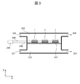
- FIG. 3 is a schematic diagram showing an example of the configuration of a fuel cell module using a thin film process type solid oxide fuel cell (SOFC) according to the first embodiment.
- the gas flow path in the fuel cell module includes a fuel gas introduction port 201, a fuel gas chamber 202, a fuel gas exhaust port 203, which are fuel gas flow paths, and a flow of, for example, air containing oxygen gas. It is separated into an air inlet port 204, an air chamber 205, and an air exhaust port 206 which are channels. The fuel gas and the air are shielded by a shield plate 207 so that they are not mixed in the module.
- a lead wire 208 is drawn out from the anode electrode and the cathode electrode of the fuel cell 1 and connected to the external load 209.
- the fuel cell 1 is mounted on the shield plate 207.
- the number of the fuel cells 1 may be one, generally, a plurality of the fuel cells 1 are arranged.
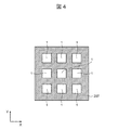
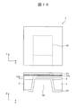
- FIG. 4 is a view seen from the fuel cell 1 side (air chamber side) on the shielding plate 207.
- FIG. 5 is a view seen from the back side (fuel gas chamber side) of the shielding plate 207.
- a hole 210 is formed in the shielding plate 207 for each fuel cell 1 so that the fuel gas is supplied to the fuel cell 1 from the fuel gas chamber.
- the anode electrode is formed in contact with the fuel gas
- the cathode electrode is formed in contact with the air.
- FIG. 6 is a schematic diagram showing an example of the configuration of a thin film process type solid oxide fuel cell (SOFC) according to the first embodiment, and corresponds to the fuel cell 1 shown in FIGS. 3 to 5.
- the insulating film 3 is formed on the upper surface of the substrate 2 made of silicon or the like.
- the insulating film 3 can be formed of, for example, a silicon oxide film or a silicon nitride film.
- An opening 50 is formed in the center of the substrate 2.
- YSZ yttria-doped polycrystalline zirconia
- the thickness of the solid electrolyte layer 100 can be, for example, 1000 nm or less. In order to obtain sufficient proton conductivity, the thickness is preferably in the range of 10 nm or more and 500 nm or less. Since YSZ has an extremely small electron current and hole current, which are internal leak currents of the fuel cell, even at high temperatures, YSZ can be thinned to 100 nm or less.
- the solid electrolyte layer 100 is formed so as to completely cover the opening 50.
- a second metal layer serving as the anode electrode 20 is formed on the lower layer of the substrate 2, that is, on the opposite side of the substrate 2 where the solid electrolyte layer 100 is formed in the Z direction.
- the second metal layer can be formed of platinum, for example, and is in contact with the solid electrolyte layer 100 through the opening 50.
- a polycrystalline titanium oxide film to be the first oxygen ion blocking layer 110 is formed on the upper layer of the solid electrolyte layer 100.
- a first metal layer serving as the cathode electrode 10 is formed on the first oxygen ion blocking layer 110.
- the first metal layer can be formed of platinum, for example.
- the polycrystalline titanium oxide forming the first oxygen ion blocking layer 110 has low oxygen ion conductivity but high proton conductivity. That is, it has a function of selectively permeating only protons out of oxygen ions and protons.
- a 3d transition metal oxide such as nickel oxide or a polycrystalline film such as alumina has a similar function and can be used as the first oxygen ion blocking layer 110.
- the second metal layer (platinum) serving as the anode electrode 20 from the lower layer, the solid electrolyte layer 100 (polycrystalline YSZ), the first oxygen ion blocking layer 110 (polycrystalline titanium oxide), and the cathode electrode 10 are formed.
- the fuel cell 1 including the membrane electrode assembly for a fuel cell composed of the first metal layer (platinum) the fuel gas containing hydrogen, for example, on the anode electrode 20 side, the air, for example, on the cathode electrode 10 side.
- a gas containing oxygen is supplied.
- the anode electrode 20 side and the cathode electrode 10 side are sealed so that the two kinds of gas to be supplied are not mixed with each other.
- the substrate 2 is a silicon substrate
- the solid electrolyte layer 100 is YSZ
- the cathode electrode 10 is platinum
- the anode electrode 20 is platinum.
- the following modifications are, of course, possible.
- the substrate 2 may be formed of a member containing ceramic, glass, or steel instead of the silicon substrate.
- the solid electrolyte layer 100 can also use polycrystalline zirconia doped with divalent or trivalent positive ions other than Y.
- the positive ions to be doped can be Y 3+ , for example Mg 2+ , Ca 2+ or Sc 3+ .
- the solid electrolyte layer 100 may use ceria doped with divalent or trivalent positive ions.
- the positive ions to be doped can be, for example, Gd 3+ or Sm 3+ .
- the cathode electrode 10 is made of, for example, gold, palladium, iridium, rhodium, ruthenium, osmium, (La 1-x Sr x )(Co 1-y Fe y )O 3 (for example, La 0.6 Sr 0 ) instead of platinum. .4 Co 0.8 Fe 0.2 O 3- ⁇ (where 0 ⁇ 0.7), Sm 0.5 Sr 0.5 CoO 3 , Ba 0.8 La 0.2 CoO 3 , It may contain one or more selected from the group consisting of Gd 0.5 Sr 0.5 CoO 3 , (La 1-x Sr x )MnO 3 and (La 1-x Sr x )FeO 3 .
- the cathode electrode 10 may be formed of a composite material of the same material as the oxygen ion blocking layer 110, instead of platinum, and, for example, gold, palladium, iridium, rhodium, ruthenium, osmium, or the like.
- the anode electrode 20 may be made of, for example, (Ce 1-x Sm x )O 2 doped with copper or nickel, (Ce 1-x Gd x )O 2 doped with copper or nickel, or nickel instead of platinum. It may include one or more selected from the group consisting of doped YSZ, platinum, gold, palladium, iridium, rhodium, ruthenium and osmium (where 0 ⁇ x ⁇ 1, 0 ⁇ y ⁇ 1).
- FIG. 7A shows the movement of oxygen ions and protons in the SOFC of the first embodiment.
- Oxygen ions are generated from the oxygen gas in the atmosphere on the cathode electrode 10 side, and at that time, electrons are taken from the cathode electrode 10.
- the cathode electrode 10 is positively charged. Since the oxygen ion blocking layer 110 is formed between the cathode electrode 10 and the solid electrolyte layer 100, the generated oxygen ions hardly diffuse into the solid electrolyte layer 100.
- Protons are generated from the hydrogen gas in the atmosphere on the anode electrode 20 side, and at that time, electrons are emitted to the anode electrode 20. As a result, the anode electrode 20 is negatively charged.
- the generated protons diffuse in the solid electrolyte layer 100, diffuse in the oxygen ion blocking layer 110, and reach the cathode electrode 10. Here, it reacts with oxygen to produce water.
- the anode electrode 20 and the cathode electrode 10 are electrically connected to each other outside the fuel cell, a current flows, and in parallel therewith, water is continuously produced in the cathode electrode 10. Since it is released into the atmosphere on the side of, the water is not generated and does not stay in the solid electrolyte layer 100.
- Fig. 7(b) shows the movement of oxygen ions and protons in the conventional SOFC.
- Oxygen ions are generated from the oxygen gas in the atmosphere on the cathode electrode 10 side, and at that time, electrons are taken from the cathode electrode 10.
- the cathode electrode 10 is positively charged.
- the generated oxygen ions diffuse into the solid electrolyte layer 100.
- Protons are generated from the hydrogen gas in the atmosphere on the anode electrode 20 side, and at that time, electrons are emitted to the anode electrode 20.
- the anode electrode 20 is negatively charged.
- the generated protons also diffuse in the solid electrolyte layer 100.
- the structure including the oxygen ion blocking layer 110 of the first embodiment By using the structure including the oxygen ion blocking layer 110 of the first embodiment, the retention of water inside the solid electrolyte layer 100 is suppressed, and high-efficiency power generation utilizing the proton conduction characteristics of the solid electrolyte layer 100 is achieved. realizable.
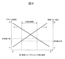
- FIG. 8 is a graph showing the relationship between the film thickness of the first oxygen ion blocking layer and the proton conductivity in the first embodiment. As shown in FIG. 8, as the thickness of the first oxygen ion blocking layer is increased, the effect of oxygen ion blocking is enhanced, but there is a side effect of decreasing proton conductivity. Therefore, the first oxygen ion blocking layer has a suitable film thickness. Although it depends on the material used for the first ion blocking layer, for example, several tens of nanometers to several micrometers is a suitable thickness range.
- the doped zirconia is superior in the first embodiment in which the conduction of oxygen ions needs to be blocked, although it is suitable for the solid electrolyte layer.
- the relationship between the doped zirconia and the doped ceria used as the solid electrolyte layer 100 is the same in the following second to sixth embodiments.
- the anode electrode 20, the solid electrolyte layer 100, the first oxygen ion blocking layer 110, and the cathode electrode 10 are arranged in this order from the lower layer to form a fuel cell membrane electrode assembly.
- the anode electrode 20 is formed in the lower layer of the substrate 2, and the solid electrolyte layer 100, the first oxygen ion blocking layer 110, and the cathode electrode 10 are formed in the upper layer of the substrate 2, but other configurations are also applicable. Is.
- the arrangement order of the constituent members of the membrane electrode assembly for a fuel cell in FIG. 9 from the lower layer is the same as that of the first embodiment, but in FIG. 9, unlike the first embodiment, the anode electrode 20 and the solid electrolyte layer 100 are the substrate 2
- the first oxygen ion blocking layer 110 and the cathode electrode 10 are formed on the lower layer of the substrate 2, and are formed on the upper layer of the substrate 2.
- the arrangement order from the lower layer of the constituent members of the fuel cell membrane electrode assembly in FIG. 10 is also the same as that in the first embodiment, but in FIG. 10, unlike the first embodiment and FIG. 9, the anode electrode 20, the solid electrolyte layer are different. 100 and the first oxygen ion blocking layer 110 are formed on the lower layer of the substrate 2, and only the cathode electrode 10 is formed on the upper layer of the substrate 2.
- the order of arrangement of the constituent members of the fuel cell membrane electrode assembly from the lower layer is different from that of the first embodiment and the configurations shown in FIGS. 9 to 10, from the lower layer to the cathode electrode 10, the first electrode.
- the oxygen ion blocking layer 110, the solid electrolyte layer 100, and the anode electrode 20 are formed in this order.
- the cathode electrode 10 is formed in the lower layer of the substrate 2, and the first oxygen ion blocking layer 110, the solid electrolyte layer 100, and the anode electrode 20 are formed in the upper layer of the substrate 2.
- the cathode electrode 10 and the first oxygen ion blocking layer 110 are formed in the lower layer of the substrate 2, and the solid electrolyte layer 100 and the anode electrode 20 are formed in the upper layer of the substrate 2.
- the cathode electrode 10, the first oxygen ion blocking layer 110, and the solid electrolyte layer 100 are formed in the lower layer of the substrate 2, and only the anode electrode 20 is formed in the upper layer of the substrate 2.
- the arrangement order of the constituent members of the fuel cell membrane electrode assembly from the lower layer is the same as in FIGS. 11 to 13, from the lower layer to the cathode electrode 10, the first oxygen ion blocking layer, the solid electrolyte layer 100, and the anode.
- the electrodes 20 are formed in this order, but a part 110A of the first oxygen ion blocking layer is formed from the upper surface of the substrate 2, and another part 110B of the first oxygen ion blocking layer is formed on the lower surface of the substrate 2. Are formed from.
- the arrangement order of the constituent members of the fuel cell membrane electrode assembly from the lower layer is the same as in the first embodiment, from the lower layer to the anode electrode 20, the solid electrolyte layer 100, the first oxygen ion blocking layer, and the cathode electrode 10. Even in the case of the configuration, it is of course possible to configure the first oxygen ion blocking layer with the formation portion on the upper layer of the substrate 2 and the formation portion on the lower layer of the substrate 2.
- the polycrystalline titanium oxide forming the first oxygen ion blocking layer 110 has a low oxygen ion conductivity but a high proton conductivity. That is, it has a function of selectively permeating only protons out of oxygen ions and protons.
- a 3d transition metal oxide such as nickel oxide, or a polycrystalline film such as alumina has a similar function, and can be used as the first oxygen ion blocking layer 110.
- the solid electrolyte layer 100 can use YSZ, the first metal layer that will be the cathode electrode 10 can be platinum, and the second metal layer that will be the anode electrode 20 can be platinum. However, as shown in the modification of the first embodiment. It is also possible to use the respective materials.
- the structure including the oxygen ion blocking layer 110 similarly to the first embodiment, by using the structure including the oxygen ion blocking layer 110, the retention of water inside the solid electrolyte layer 100 is suppressed, It is possible to realize highly efficient power generation by making use of the proton conduction characteristics of the solid electrolyte layer 100.
- the configuration of the fuel cell according to the third embodiment will be described with reference to FIGS.
- the anode electrode 20, the solid electrolyte layer 100, the first oxygen ion blocking layer 110, and the cathode electrode 10 are formed in this order from the lower layer. It is similar to the first embodiment in that the body completely covers the opening of the substrate 2, but is different in that all the constituent members of the fuel cell membrane electrode assembly are formed in the upper layer of the substrate 2. ..
- the lower layer side electrode (anode electrode 20 in FIG. 15) and the upper layer side electrode (cathode electrode 10 in FIG. 15) are the upper layer side. Therefore, it is necessary to form the solid electrolyte layer 100, the first oxygen ion blocking layer 110, and the exposed region 51 without the cathode electrode 10 on the anode electrode 20 as shown in FIG. is there.
- the anode electrode 20 similarly to the embodiment shown in FIG. 15, the anode electrode 20, the solid electrolyte layer 100, the first oxygen ion blocking layer 110, and the cathode electrode 10 are formed in this order from the lower layer. All the constituent members of the fuel cell membrane electrode assembly are formed in the upper layer of the substrate 2. However, in FIG. 16, nickel, which is a conductive material, is used as the substrate 2, and it is different in that the substrate 2 and the anode electrode 20 are electrically connected.
- the polycrystalline titanium oxide forming the first oxygen ion blocking layer 110 has a low oxygen ion conductivity but a high proton conductivity. That is, it has a function of selectively permeating only protons out of oxygen ions and protons.
- a 3d transition metal oxide such as nickel oxide, or a polycrystalline film such as alumina has a similar function, and can be used as the first oxygen ion blocking layer 110.
- the solid electrolyte layer 100 can use YSZ, the first metal layer that will be the cathode electrode 10 can be platinum, and the second metal layer that will be the anode electrode 20 can be platinum. However, as shown in the modification of the first embodiment. It is also possible to use the respective materials.
- the thin-film process fuel cell of the third embodiment similar to the first embodiment, by adopting the structure including the first oxygen ion blocking layer 110, the retention of water inside the solid electrolyte layer 100. It is possible to realize high-efficiency power generation by suppressing the above and utilizing the proton conduction characteristics of the solid electrolyte layer 100.
- the entire thin film process type fuel cell 1 including the fuel cell membrane electrode assembly of the fourth embodiment contains, for example, a fuel gas containing hydrogen and oxygen such as air. Supply a mixture of gases. The same mixed gas is supplied to the anode electrode 20 and the cathode electrode 10, but since the materials and shapes of the electrodes are different, a potential difference occurs and power is generated.
- a fuel cell is called a single chamber type fuel cell.
- the single chamber type fuel cell has an advantage that the system can be simplified and the system cost can be reduced because it is not necessary to separate and seal the gas system containing the fuel gas and the gas system containing the oxidant such as oxygen. ..
- FIG. 17 is a schematic diagram showing an example of the configuration of a fuel cell module using the thin film process type SOFC of the fourth embodiment.
- the gas introduced into the module is a mixed gas containing oxygen and hydrogen, and the mixed gas flows along the mixed gas introduction port 301, the mixed gas chamber 302, and the mixed gas exhaust port 303, and the anode electrode and the cathode electrode in the fuel cell 1 are provided. Are formed so that they can contact the mixed gas.
- a lead wire 208 is drawn from the anode electrode and the cathode electrode of the fuel cell 1 and connected to the external load 209.
- the fuel cell 1 is mounted on the support substrate 304. Although the number of the fuel cells 1 may be one, generally a plurality of the fuel cells 1 are arranged.
- FIG. 18 shows a structure suitable for use as a single chamber fuel cell.
- hydrogen gas and oxygen gas are supplied to both the anode electrode 20 and the cathode electrode 10.
- protons are mainly produced by the catalytic reaction in the anode electrode 20.
- a part of the generated protons reacts with oxygen ions in situ to generate water, but the remaining part diffuses into the solid electrolyte layer 100. Since the generation of protons at the anode electrode 20 is faster than that at the cathode electrode 10, protons as a whole flow from the anode electrode 20 to the cathode electrode 10 via the solid electrolyte layer 100 and the first oxygen ion blocking layer 110. ..
- Oxygen ions generated at the cathode electrode 10 partially diffuse into the solid electrolyte layer 100 without the first oxygen ion blocking layer 110, and combine with protons inside the solid electrolyte layer 100 to generate water. The generated water stays and reduces the electromotive force.
- the first oxygen ion blocking layer 110 at the boundary between the cathode electrode 10 and the solid electrolyte layer 100, the diffusion of oxygen ions from the cathode electrode 10 is suppressed, and the generation of water inside the solid electrolyte layer 100 is suppressed. Since it is suppressed, a decrease in electromotive force can be prevented.
- the polycrystalline titanium oxide forming the first oxygen ion blocking layer 110 has a low oxygen ion conductivity but a high proton conductivity. That is, it has a function of selectively permeating only protons out of oxygen ions and protons.
- a 3d transition metal oxide such as nickel oxide, or a polycrystalline film such as alumina has a similar function, and can be used as the first oxygen ion blocking layer 110.
- the first metal layer to be the cathode electrode 10 can be platinum
- the second metal layer to be the anode electrode 20 can be platinum, but the materials shown in the modification of the first embodiment can also be used for each. Is.
- FIG. 20 shows an example of forming a thin film process type fuel cell provided with a membrane electrode assembly for a single chamber type fuel cell without forming an opening in the substrate 2.
- the first oxygen ion blocking layer 110, the solid electrolyte layer 100, and the anode electrode 20 are formed on the cathode electrode 10 formed on the surface of the substrate 2.
- the cathode electrode 10 is partially exposed for power supply.
- the anode electrode 20 is formed in a stripe shape extending in the Y direction.
- the proton generation due to the catalytic reaction at the anode electrode 20 occurs most efficiently at the outer edge of the anode electrode 20, so that the stripe-shaped structure for increasing the peripheral length of the anode electrode 20 improves the power generation efficiency. It is valid.
- the substrate 2 is formed of an electric conductor as in the third embodiment, the cathode electrode 10 and the substrate 2 can be electrically connected and the cathode electrode 10 can be fed with power via the substrate 2. The exposed portion of the cathode electrode 10 as shown in FIG. 20 is unnecessary.
- the fuel cell membrane electrode assembly of the fifth embodiment includes, in addition to the anode electrode 20, the solid electrolyte layer 100, the first oxygen ion blocking layer 110, and the cathode electrode 10, As shown in FIG. 21, a second oxygen ion blocking layer 120 is formed between the anode electrode 20 and the solid electrolyte layer 100.
- the entire thin film process fuel cell 1 including the fuel cell membrane electrode assembly including the layer 110 (for example, polycrystalline titanium oxide) and the first metal layer (for example, platinum) that becomes the cathode electrode 10 is formed by, for example, hydrogen.
- a mixed gas of a fuel gas containing oxygen and a gas containing oxygen such as air is supplied.
- the fuel cell of the fifth embodiment is called a single chamber type fuel cell.
- the single chamber type fuel cell has an advantage that the system can be simplified and the system cost can be reduced because it is not necessary to separate and seal the gas system containing the fuel gas and the gas system containing the oxidant such as oxygen. ..
- FIG. 21 shows a structure different from that of the fourth embodiment which is suitable for use in a single chamber type fuel cell.
- hydrogen gas and oxygen gas are supplied to both the anode electrode 20 and the cathode electrode 10. Therefore, as shown in FIG. 22, protons and oxygen ions are generated by a catalytic reaction in both electrodes. Is generated. A part of the generated protons reacts with oxygen ions in situ to generate water, but the remaining part diffuses into the solid electrolyte layer 100.
- the protons as a whole are transferred from the anode electrode 20 to the second oxygen ion blocking layer 120, the solid electrolyte layer 100, and the first oxygen ion blocking layer. It flows to the cathode electrode 10 via 110. Oxygen ions generated at the anode electrode 20 partly diffuse into the solid electrolyte layer 100 without the second oxygen ion blocking layer 120, and combine with protons inside the solid electrolyte layer 100 to generate water. The generated water stays and reduces the electromotive force.
- the second oxygen ion blocking layer 120 formed on the boundary between the anode electrode 20 and the solid electrolyte layer 100 suppresses the diffusion of oxygen ions from the anode electrode 20 and suppresses the generation of water inside the solid electrolyte layer 100. Therefore, it is possible to prevent a decrease in electromotive force.
- the role of the first oxygen ion blocking layer 110 formed at the boundary between the cathode electrode 10 and the solid electrolyte layer 100 is the same as in the first to fourth embodiments.
- the polycrystalline titanium oxide forming the first oxygen ion blocking layer 110 has a low oxygen ion conductivity but a high proton conductivity. That is, it has a function of selectively permeating only protons out of oxygen ions and protons.
- a 3d transition metal oxide such as nickel oxide, or a polycrystalline film such as alumina has a similar function, and can be used as the first oxygen ion blocking layer 110.
- the same material as the first oxygen ion blocking layer 110 can be used for the second oxygen ion blocking layer 120.
- YSZ can be used as the solid electrolyte layer 100, it is also possible to use the material shown in the modification of the first embodiment.
- Platinum can be used for the first metal layer to be the cathode electrode 10 and nickel can be used for the second metal layer to be the anode electrode 20, but the materials shown in the modification of the first embodiment can also be used for each. It is possible.
- the arrangement order of the constituent members of the fuel cell membrane electrode assembly can be reversed upside down.
- the membrane electrode assembly for a fuel cell is composed of an anode electrode 20, a second oxygen ion blocking layer 120, a solid electrolyte layer 100, a first oxygen ion blocking layer 110, and a cathode electrode 10 in this order from the lower layer.
- anode electrode 20 as a lower layer
- a second oxygen ion blocking layer 120 as an upper layer
- a solid electrolyte layer 100 as a first oxygen ion blocking layer 110, and a cathode electrode 10.
- the second example is the anode electrode 20, the second oxygen ion blocking layer 120 as the lower layer, the solid electrolyte layer 100, the first oxygen ion blocking layer 110, and the cathode electrode 10 as the upper layer.
- the lower layer is the anode electrode 20, the second oxygen ion blocking layer 120, the solid electrolyte layer 100, and the upper layer is the first oxygen ion blocking layer 110 and the cathode electrode 10.
- the lower layer is the anode electrode 20, the second oxygen ion blocking layer 120, the solid electrolyte layer 100, the first oxygen ion blocking layer 110, and the upper layer is the cathode electrode 10.
- the membrane electrode assembly for a fuel cell is composed of the cathode electrode 10, the first oxygen ion blocking layer 110, the solid electrolyte layer 100, the second oxygen ion blocking layer 120, and the anode electrode 20 in this order from the lower layer, There are the following combinations for forming the lower layer and the upper layer.
- the first example is the cathode electrode 10 as the lower layer, the first oxygen ion blocking layer 110 as the upper layer, the solid electrolyte layer 100, the second oxygen ion blocking layer 120, and the anode electrode 20.
- the second example is the cathode electrode 10, the first oxygen ion blocking layer 110 as the lower layer, the solid electrolyte layer 100, the second oxygen ion blocking layer 120, and the anode electrode 20 as the upper layer.
- the lower layer is the cathode electrode 10, the first oxygen ion blocking layer 110, the solid electrolyte layer 100, and the upper layer is the second oxygen ion blocking layer 120, and the anode electrode 20.
- the lower layer is the cathode electrode 10, the first oxygen ion blocking layer 110, the solid electrolyte layer 100, the second oxygen ion blocking layer 120, and the upper layer is the anode electrode 20.
- one of the constituent members of the membrane electrode assembly for a fuel cell is formed from the upper layer of the substrate 2 and the lower layer of the substrate 2. It is also possible to form both layers.
- the opening of the substrate 2 may not be formed as in the case of FIG. 20 of the fourth embodiment.
- the number of manufacturing steps is increased because it is necessary to form the second oxygen ion blocking layer as compared with the fourth embodiment.
- oxygen ions generated in the anode electrode 20 can be prevented from invading the solid electrolyte layer 100, so that the effect of suppressing a decrease in electromotive force due to the retention of water in the solid electrolyte layer 100 is great.
- the fuel cell membrane electrode assembly of the fourth embodiment is inferior to the fifth embodiment in suppressing the decrease in electromotive force due to the retention of water in the solid electrolyte layer, but is effective in a small number of manufacturing steps. Can be obtained.
- the cathode electrode 10 and the anode electrode 20 of the first to fifth embodiments are made of a composite material.
- the cathode electrode 10 and the anode electrode 20 can be configured as shown in FIG. 23, for example.
- the cathode electrode 10 in FIG. 23 can be formed of, for example, a composite material of a metal oxide and a metal used for the first oxygen ion blocking layer 110.
- the cathode electrode 10 is formed of a composite material layer MX (Pt, TiOx) of platinum and titanium oxide.
- the anode electrode 20 can be formed of a composite material of the material used for the solid electrolyte layer 100 and a metal.
- the anode electrode 20 is formed of a composite material layer MX (YSZ, Ni) of YSZ and nickel.
- the cathode electrode 10 and the anode electrode 20 can be configured as shown in FIG. 24, for example.
- the cathode electrode 10 can be formed of, for example, a composite material of a metal oxide and a metal used for the first oxygen ion blocking layer 110.
- the cathode electrode 10 is formed of a composite material layer MX (Pt, TiOx) of platinum and titanium oxide.
- the anode electrode 20 can be formed of, for example, a composite material of a metal oxide and a metal used for the second oxygen ion blocking layer 120.
- the anode electrode 20 is formed of a nickel oxide/nickel composite material layer MX (NiO, Ni).
- the composite material can be formed by a method such as sputter film formation using a target having the same composition as the composite material, or simultaneous sputtering film formation using two targets of each constituent material.
- the composite material layer MX Pt, TiOx
- the composite material layer MX made of titanium oxide and a metal that is difficult to oxidize such as platinum is formed by forming a composite material layer of platinum and titanium metal and then annealing and oxidizing it in an atmosphere containing oxygen. It can also be formed.
Landscapes
- Engineering & Computer Science (AREA)
- Manufacturing & Machinery (AREA)
- Chemical & Material Sciences (AREA)
- Chemical Kinetics & Catalysis (AREA)
- Electrochemistry (AREA)
- General Chemical & Material Sciences (AREA)
- Life Sciences & Earth Sciences (AREA)
- Sustainable Development (AREA)
- Sustainable Energy (AREA)
- Ceramic Engineering (AREA)
- Fuel Cell (AREA)
- Inert Electrodes (AREA)
Abstract
発電効率が高く、低温で動作可能な固体酸化物形燃料電池を提供する。 本発明の燃料電池1は、カソード電極10と、アノード電極20と、カソード電極10及びアノード電極20の間に配置される、2価又は3価の正イオンがドーピングされプロトン伝導性を有する多結晶ジルコニア又は多結晶セリアからなる固体電解質層100と、を備え、カソード電極10と固体電解質層100とが、第1の酸素イオンブロッキング層110を介して積層されることを特徴とする。
Description
本発明は、燃料電池セル及び燃料電池モジュールに関する。
アノード電極に接触した燃料ガスから生じるプロトンが固体酸化物からなる電解質中を伝導し、カソードで酸素イオンと結合して水が生じることで発電する固体酸化物形のプロトン伝導型燃料電池に関し、背景技術として、特許文献1~4及び非特許文献1に記載の発明が知られている。
非特許文献1には、薄膜成膜プロセスによって燃料電池膜のアノード層、固体電解質層及びカソード層を形成するセル技術について記載されている。固体電解質を薄膜化することでイオン伝導度を向上させ発電効率を高めることができる。固体電解質のイオン伝導度は、活性化型の温度依存性を示す。したがって、イオン伝導度は高温で大きく、低温では小さい。固体電解質の薄膜化により、低温でも充分大きなイオン伝導度が得られ、実用的な発電効率が実現できる。固体電解質層としては、例えばイットリアをドーピングしたジルコニアであるYSZ(Yttria Stabilized Zirconia)等が用いられることが多い。化学的安定性に優れ、燃料電池の内部リーク電流の原因となる電子、ホールによる電流が少ないという長所があるためである。
特許文献1には、固体電解質にBaCeO3、SrCeO3といったプロトン伝導体を用いる燃料電池技術が開示されている。これらの固体電解質は、プロトン伝導率が大きいため発電効率の向上に有利である。しかし、この固体電解質は、二酸化炭素ガスに触れると反応しBaCO3、SrCO3といった炭酸塩が生成され燃料電池の性能を著しく劣化させることが知られている。特許文献1には、二酸化炭素ガスが燃料の改質ガス中に含まれている場合を想定し、燃料となる水素は透過させるが二酸化炭素は透過させないパラジウム(Pd)膜を固体電解質膜の表面に形成する技術が記載されている。
特許文献2には、水素透過性の陽極(アノード)基材上の固体電解質層にプロトン伝導体であるBaZrO3、SrZrO3等を用いる燃料電池技術が記載されている。BaZrO3、SrZrO3の主な電荷担体はプロトンであるが、酸素イオン(O2-)も伝導する。カソード側で雰囲気中の酸素ガスから生じる酸素イオンが固体電解質層を伝導して水素透過性の陽極基材と固体電解質層の境界部に至ると水素と反応して水が生成し、陽極基材と固体電解質層の接着性を劣化させる課題が挙げられている。この課題を解決するため、カソード電極とBaZrO3、SrZrO3等の固体電解質層との間に、酸素欠損量の少ない酸化物からなる介在層を形成することで酸素イオンの伝導を抑制することが記載されている。
特許文献3には、酸素イオン伝導体Bi2O3を用いた燃料電池において、酸素イオン以外の電荷担体、すなわち、プロトン、電子、ホールによる電流を抑制するために、プロトンブロック層、電子電流ブロック層、ホール電流ブロック層を設ける技術が記載されている。
特許文献4には、酸素と燃料を混合したガスをアノード電極とカソード電極の両方に供給するシングルチャンバ型の燃料電池に関する技術が記載されている。燃料ガスと酸素ガスをそれぞれアノード電極側とカソード電極側に供給するよりも燃料電池の構造を簡単にすることができる。
Journal of Power Sources 194 (2009) 119-129
YSZ等のようなドーピングしたジルコニアは酸素イオン伝導体として知られているが、イオン伝導率があまり高くないという問題点があった。これに対し、本発明者らは、ドーピングしたジルコニアの発電効率を向上させるべく薄膜化を行ったところ、酸素イオン伝導を上回るプロトン伝導が生じることを初めて見い出した。燃料電池の固体電解質層にドーピングした薄膜ジルコニアを用いると、プロトン伝導と酸素イオン伝導の両方が生じるため、固体電解質中で水が生成される。生じた水を速やかに雰囲気中に除去しないと起電力の低下が起こる。そこで本発明は、薄膜化によりプロトン伝導性が現れる、ドーピングしたジルコニアを固体電解質層として備える燃料電池を用い、その燃料電池において酸素イオンが固体電解質層中を伝導するのを防止し、固体電解質層中での水の生成を抑制することを目的とする。
また、ドーピングしたジルコニアと同様に、バルク状態では酸素イオン伝導体であるが薄膜化によってプロトン伝導を発現する物質にドーピングしたセリアがある。そこで本発明は、ドーピングした薄膜セリアを固体電解質層に用いた燃料電池において、カソードで生じる酸素イオンが固体電解質中を伝導するのを防止し、固体電解質中での水の生成を抑制することも目的とする。
本発明者らは、固体酸化物形燃料電池(SOFC)の酸素ガスに曝されるカソード電極と、ドーピングした薄膜ジルコニアあるいはドーピングした薄膜セリアで形成する固体電解質層との間に、酸素イオン伝導度が固体電解質層よりも低い酸素イオンブロッキング層を形成することにより上記課題が解決することを見い出し、発明を完成した。
すなわち、本発明の燃料電池は、カソード電極と、アノード電極と、前記カソード電極及び前記アノード電極の間に配置される、2価又は3価の正イオンがドーピングされプロトン伝導性を有する多結晶ジルコニア又は多結晶セリアからなる固体電解質層と、を備え、前記カソード電極と前記固体電解質層とが、第1の酸素イオンブロッキング層を介して積層されることを特徴とする。
また、特許文献4に記載されているシングルチャンバ型の燃料電池の場合には、両側の電極が酸素ガスに曝され、両方の電極において酸素から酸素イオンが生成される。この場合、ドーピングした薄膜ジルコニアあるいはドーピングした薄膜セリアで形成する固体電解質層に酸素イオンが拡散しないように、酸素イオンブロッキング層を両方の電極と固体電界質層との境界に形成することができる。
本発明によれば、発電効率が高く、低温で動作可能な燃料電池、及びそれを用いた燃料電池モジュールを提供することができる。上記した以外の課題、構成及び効果は、以下の実施の形態の説明により明らかにされる。
以下、実施の形態により本発明を詳細に説明する。なお、実施の形態を説明するための全図において、同一の機能を有する部材には同一又は関連する符号を付し、その繰り返しの説明は省略する。また、複数の類似の部材(部位)が存在する場合には、総称の符号に記号を追加し個別又は特定の部位を示す場合がある。また、以下の実施の形態では、特に必要なとき以外は同一又は同様の部分についての説明を原則として繰り返さない。
また、以下の実施の形態においては、説明上の方向として、X方向、Y方向及びZ方向を用いる。X方向とY方向とは互いに直交し、水平面を構成する方向であり、Z方向は水平面に対して鉛直の方向である。
また、実施形態の説明で用いる図面においては、断面図であっても図面を見やすくするためにハッチングを省略する場合がある。また、平面図であっても図面を見やくするためにハッチングを付す場合もある。
また、断面図及び平面図において、各部位の大きさは実デバイスと対応するものではなく、図面を分かりやすくするため、特定の部位を相対的に大きく表示する場合がある。また、断面図と平面図が対応する場合においても、図面を分かりやすくするため、特定の部位を相対的に大きく表示する場合がある。
<薄膜プロセス型燃料電池による発電効率の向上及び動作温度の低温化>
一般に、燃料電池の発電効率を上げ、低温動作を実現するためには、燃料電池用膜電極接合体を構成するアノード電極、固体電解質層及びカソード電極を薄膜化する必要があり、そのためには成膜プロセスでアノード電極、固体電解質層及びカソード電極を形成する薄膜プロセス型燃料電池が最適である。図1は、従来の薄膜プロセス型燃料電池の構成の一例を示す概略図である。図1の燃料電池1は、アノード電極20、固体電解質層100及びカソード電極10を備える。アノード電極20、固体電解質層100、カソード電極10を全て薄膜化すると、燃料電池用膜電極接合体の機械的強度が弱くなるが、図1に示すように接合体を基板2で支持することにより、機械的強度を補うことができる。基板2と固体電解質層100との間には、絶縁膜3が設けられる。また、基板2の中央には開口部50が設けられ、開口部50においてアノード電極20と固体電解質層100とが接触している。基板としては、例えばシリコン、セラミック、ガラス、SUS等を用いることができる。
一般に、燃料電池の発電効率を上げ、低温動作を実現するためには、燃料電池用膜電極接合体を構成するアノード電極、固体電解質層及びカソード電極を薄膜化する必要があり、そのためには成膜プロセスでアノード電極、固体電解質層及びカソード電極を形成する薄膜プロセス型燃料電池が最適である。図1は、従来の薄膜プロセス型燃料電池の構成の一例を示す概略図である。図1の燃料電池1は、アノード電極20、固体電解質層100及びカソード電極10を備える。アノード電極20、固体電解質層100、カソード電極10を全て薄膜化すると、燃料電池用膜電極接合体の機械的強度が弱くなるが、図1に示すように接合体を基板2で支持することにより、機械的強度を補うことができる。基板2と固体電解質層100との間には、絶縁膜3が設けられる。また、基板2の中央には開口部50が設けられ、開口部50においてアノード電極20と固体電解質層100とが接触している。基板としては、例えばシリコン、セラミック、ガラス、SUS等を用いることができる。
(第1実施形態)
<薄膜化した固体電解質層>
イットリアをドープしたジルコニア(YSZ)は、バルク状態では高温で酸素イオン伝導体となり、酸素イオン伝導度と比較してプロトン伝導度、電子伝導度、ホール伝導度は非常に低いことが知られている。しかし、本発明者らは、薄膜化した多結晶膜においてバルクでは見られなかった高いプロトン伝導性が現れることを見出した。
<薄膜化した固体電解質層>
イットリアをドープしたジルコニア(YSZ)は、バルク状態では高温で酸素イオン伝導体となり、酸素イオン伝導度と比較してプロトン伝導度、電子伝導度、ホール伝導度は非常に低いことが知られている。しかし、本発明者らは、薄膜化した多結晶膜においてバルクでは見られなかった高いプロトン伝導性が現れることを見出した。
図2は、YSZを流れる電流の雰囲気依存性を示すデータである。具体的には、イットリアをドーピングした薄膜ジルコニアの水素イオン伝導による電流を測定した結果を示すグラフである。電極には白金を用い、イットリアを8%ドーピングした膜厚500nmのジルコニア薄膜で測定を行った。実験では、YSZの表面に白金電極を形成し、電極間に一定電圧を印加したまま雰囲気中の水素濃度を変化させた。ベースガスは窒素である。水素の濃度を0%から3%に変化させる度に電流が増加する現象が見られた。この結果はプロトン伝導による電流が流れていることを示している。同じサンプルについて水素濃度の代わりに酸素濃度を変化させた場合と比較して、図2で見られた電流は10倍以上大きい。このようにバルクでは酸素イオン伝導体である固体電解質が、薄膜化によってプロトン伝導性を示すことが分かったので、これらの固体電解質を固体電解質層に用いて第1実施形態に係る燃料電池を作製した。
上記のイットリアをドーピングした薄膜ジルコニアの他にも、2価又は3価の正イオンをジルコニウムサイトにドーピングした多結晶ジルコニア、又は2価又は3価の正イオンをセリウムサイトにドーピングした多結晶セリアは、薄膜化によってプロトン伝導性を示すとともに、(BaY)ZrO3、(SrY)ZrO3、(BaY)CeO3、(SrY)CeO3等と比較して、二酸化炭素に触れても分解しないといった化学的安定性に優れる。また、2価又は3価の正イオンをジルコニウムサイトにドーピングした多結晶ジルコニアは、燃料電池の内部リーク電流となる電子電流、ホール電流が少ないので、固体電解質層を薄膜化して発電効率を向上させることができる。
プロトン伝導体として比較対象となる上述の(BaY)ZrO3、(SrY)ZrO3、(BaY)CeO3、(SrY)CeO3のうち、特許文献2には(BaY)CeO3又は(SrY)CeO3を固体電解質層に用いて、これらの固体電解質層が少しだけ伝導する酸素イオンを介在層でブロックする方式が記載されている。
それに対し本実施形態では、バルク状態で酸素イオン伝導体として知られ、他の金属酸化物と比較して、電池の内部リークになる電子電流、ホール電流が極めて少ないドープトジルコニアを固体電解質層に用いる。ドープトジルコニアの優れた性質にも関わらず、他のイオン伝導体が従来検討されていたのは、ドープトジルコニアの酸素イオン伝導度が発電性能の向上には不十分であったためであるが、本発明者らの検討の結果、薄膜化したドープトジルコニアではプロトン伝導性が酸素イオン伝導性を上回ることが分かった。ドープトジルコニアの性質をまとめると以下のとおりである。それぞれの項目において、左側に記載した物質がより優れている。
電子電流及びホール電流リークの少なさ: ドープトジルコニア>その他のイオン伝導体
化学的安定性: ドープトジルコニア>その他のイオン伝導体
酸素イオン伝導度: LaSrGaMgO>CeGdO>ドープトジルコニア>その他の酸化物
化学的安定性: ドープトジルコニア>その他のイオン伝導体
酸素イオン伝導度: LaSrGaMgO>CeGdO>ドープトジルコニア>その他の酸化物
ドープトジルコニアのプロトン伝導率が上記の(BaY)ZrO3、(SrY)ZrO3、(BaY)CeO3、(SrY)CeO3の伝導率に及ばなかったとしても、2価又は3価の正イオンがドーピングされた多結晶ジルコニアは電子電流、ホール電流の少なさを利用して劇的に薄膜化が可能であるため、薄膜の状態でのプロトン伝導度ではこれらの材料を上回る性能が見込める。
上記多結晶ジルコニアにドーピングされる正イオンとしては、Y3+、Mg2+、Ca2+及びSc3+からなる群から選択される一種以上の正イオンが挙げられる。
ドープトジルコニアと類似した性質をもつ固体電解質に、CeGdO等の、2価又は3価の正イオンがドーピングされた多結晶セリアがある。ドープトジルコニアと同様に、CeGdO等のドープトセリアもバルクでは酸素イオン伝導体であるが、薄膜化によってプロトン伝導性を示すことが分かった。
上記多結晶セリアにドーピングされる正イオンとしては、Gd3+及びSm3+からなる群から選択される一種以上の正イオンが挙げられる。
<燃料電池及び燃料電池モジュールの構成>
第1実施形態に係る燃料電池及び燃料電池モジュールの構成について、図3~8に基づき説明する。
図3は、第1実施形態に係る薄膜プロセス型の固体酸化物形燃料電池(SOFC)を用いた燃料電池モジュールの構成の一例を示す概略図である。図3に示すように、燃料電池モジュール内のガス流路は、燃料ガスの流路である燃料ガス導入口201、燃料ガス室202、燃料ガス排気口203と、酸素ガスを含む例えば空気の流路である空気導入口204、空気室205、空気排気口206に分離されている。燃料ガスと空気はモジュール内で混ざらないように遮蔽板207で遮蔽されている。燃料電池1のアノード電極とカソード電極からは導線208が引き出されていて外部負荷209に接続される。
第1実施形態に係る燃料電池及び燃料電池モジュールの構成について、図3~8に基づき説明する。
図3は、第1実施形態に係る薄膜プロセス型の固体酸化物形燃料電池(SOFC)を用いた燃料電池モジュールの構成の一例を示す概略図である。図3に示すように、燃料電池モジュール内のガス流路は、燃料ガスの流路である燃料ガス導入口201、燃料ガス室202、燃料ガス排気口203と、酸素ガスを含む例えば空気の流路である空気導入口204、空気室205、空気排気口206に分離されている。燃料ガスと空気はモジュール内で混ざらないように遮蔽板207で遮蔽されている。燃料電池1のアノード電極とカソード電極からは導線208が引き出されていて外部負荷209に接続される。
図4に示すように、燃料電池1は遮蔽板207上に搭載されている。燃料電池1は1つでも良いが一般には複数個が並べられる。図4は遮蔽板207上の燃料電池1側(空気室側)から見た図である。そして、遮蔽板207の裏側(燃料ガス室側)から見た図が図5である。遮蔽板207には各々の燃料電池1毎に穴210が形成されていて、燃料電池1に燃料ガス室から燃料ガスが供給されるようになっている。これにより、アノード電極が燃料ガスに、カソード電極が空気にそれぞれ接触可能に形成されている。
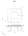
図6は、第1実施形態に係る薄膜プロセス型の固体酸化物形燃料電池(SOFC)の構成の一例を示す概略図であり、図3~5に示す燃料電池1に対応する。本実施形態では、シリコン等からなる基板2の上表面に絶縁膜3が形成されている。絶縁膜3は、例えば、シリコン酸化膜、又はシリコン窒化膜で形成することができる。基板2には中央に開口部50が形成されている。基板2の上層には、絶縁膜3を介して固体電解質層100となるイットリアをドープした多結晶ジルコニア(YSZ)等の薄膜が形成されている。固体電解質層100の厚みは例えば1000nm以下とすることができる。十分なプロトン伝導性を得るため、厚みは好ましくは10nm以上500nm以下の範囲内である。YSZは、燃料電池の内部リーク電流となる電子電流、ホール電流が高温でも極めて少ないので、100nm以下に薄膜化することも可能である。固体電解質層100は開口部50を完全に覆うように形成されている。基板2の下層、すなわち、基板2における固体電解質層100が形成されている側とZ方向で見て反対側には、アノード電極20となる第2の金属層が形成されている。第2の金属層は例えば白金で形成することができ、開口部50を介して固体電解質層100と接している。固体電解質層100の上層には、第1の酸素イオンブロッキング層110となる多結晶酸化チタン膜が形成されている。第1の酸素イオンブロッキング層110の上層にはカソード電極10となる第1の金属層が形成されている。第1の金属層は例えば白金で形成することができる。
第1の酸素イオンブロッキング層110を形成する多結晶酸化チタンは、酸素イオン伝導率が低い一方でプロトン伝導率は高い。つまり、酸素イオンとプロトンのうちプロトンだけを選択的に透過させる働きがある。多結晶酸化チタンの他に、酸化ニッケル等の3d遷移金属酸化物、アルミナ等の多結晶膜も同様の働きがあり、第1の酸素イオンブロッキング層110として用いることができる。
以上のように、下層からアノード電極20となる第2の金属層(白金)、固体電解質層100(多結晶YSZ)、第1の酸素イオンブロッキング層110(多結晶酸化チタン)、カソード電極10となる第1の金属層(白金)で構成された燃料電池用膜電極接合体を備えた薄膜プロセス型燃料電池1において、アノード電極20側に例えば水素を含む燃料ガス、カソード電極10側に例えば空気等の酸素を含むガスを供給する。供給する2種類のガスは互いに混合しないように、アノード電極20側とカソード電極10側はシールする。
<第1実施形態の変形例>
以上の説明では、基板2はシリコン基板、固体電解質層100をYSZ、カソード電極10を白金、アノード電極20を白金とした。しかし、以下のような変形は無論可能である。
以上の説明では、基板2はシリコン基板、固体電解質層100をYSZ、カソード電極10を白金、アノード電極20を白金とした。しかし、以下のような変形は無論可能である。
基板2は、シリコン基板の代わりに、セラミック、ガラス、又はスチールを含む部材で形成することも可能である。
固体電解質層100は、YSZの代わりに、Y以外の2価又は3価の正イオンがドーピングされた多結晶ジルコニアを用いることもできる。ドーピングする正イオンはY3+の他、例えばMg2+、Ca2+又はSc3+が可能である。
固体電解質層100は、YSZの代わりに、2価又は3価の正イオンがドーピングしたセリアを用いることもできる。ドーピングする正イオンは、例えばGd3+又はSm3+が可能である。
カソード電極10は、白金の代わりに、例えば、金、パラジウム、イリジウム、ロジウム、ルテニウム、オスミウム、(La1-xSrx)(Co1-yFey)O3(例えばLa0.6Sr0.4Co0.8Fe0.2O3-δ(式中、0≦δ≦0.7))、Sm0.5Sr0.5CoO3、Ba0.8La0.2CoO3、Gd0.5Sr0.5CoO3、(La1-xSrx)MnO3及び(La1-xSrx)FeO3からなる群から選択される一種以上を含むことができる。上記式中、0≦x≦1、0≦y≦1である。また、カソード電極10は、白金の代わりに、酸素イオンブロッキング層110と同じ材料と、例えば、金、パラジウム、イリジウム、ロジウム、ルテニウム、オスミウム等との複合材料で形成することもできる。
アノード電極20は、白金の代わりに、例えば、銅又はニッケルがドーピングされた(Ce1-xSmx)O2、銅又はニッケルがドーピングされた(Ce1-xGdx)O2、ニッケルがドーピングされたYSZ、白金、金、パラジウム、イリジウム、ロジウム、ルテニウム及びオスミウム(上記式中、0≦x≦1、0≦y≦1)からなる群から選択される一種以上を含むことができる。
<第1実施形態の作用効果>
第1実施形態の作用効果を図7に基づき説明する。図7(a)は、第1実施形態のSOFCにおける酸素イオンとプロトンの動きを示している。カソード電極10側で雰囲気中の酸素ガスから酸素イオンが生じ、その際にはカソード電極10から電子を奪う。その結果、カソード電極10は正に帯電する。酸素イオンブロッキング層110がカソード電極10と固体電解質層100の間に形成されているために、生じた酸素イオンは固体電解質層100にはほとんど拡散しない。アノード電極20側で雰囲気中の水素ガスからプロトンが生じ、その際にアノード電極20に電子を放出する。その結果、アノード電極20は負に帯電する。生じたプロトンは、固体電解質層100を拡散し、酸素イオンブロッキング層110を拡散しカソード電極10に至る。ここで酸素と反応して水を生成する。アノード電極20とカソード電極10を燃料電池の外部で電気的に接続すると電流が流れ、それと並行して上記のカソード電極10での水の生成が継続して起こるが、生成した水はカソード電極10の側の雰囲気中に放出されるので固体電解質層100中で水が生じて滞留することはない。
第1実施形態の作用効果を図7に基づき説明する。図7(a)は、第1実施形態のSOFCにおける酸素イオンとプロトンの動きを示している。カソード電極10側で雰囲気中の酸素ガスから酸素イオンが生じ、その際にはカソード電極10から電子を奪う。その結果、カソード電極10は正に帯電する。酸素イオンブロッキング層110がカソード電極10と固体電解質層100の間に形成されているために、生じた酸素イオンは固体電解質層100にはほとんど拡散しない。アノード電極20側で雰囲気中の水素ガスからプロトンが生じ、その際にアノード電極20に電子を放出する。その結果、アノード電極20は負に帯電する。生じたプロトンは、固体電解質層100を拡散し、酸素イオンブロッキング層110を拡散しカソード電極10に至る。ここで酸素と反応して水を生成する。アノード電極20とカソード電極10を燃料電池の外部で電気的に接続すると電流が流れ、それと並行して上記のカソード電極10での水の生成が継続して起こるが、生成した水はカソード電極10の側の雰囲気中に放出されるので固体電解質層100中で水が生じて滞留することはない。
一方、図7(b)は、従来のSOFCにおける酸素イオンとプロトンの動きを示している。カソード電極10側で雰囲気中の酸素ガスから酸素イオンが生じ、その際にはカソード電極10から電子を奪う。その結果、カソード電極10は正に帯電する。生じた酸素イオンは固体電解質層100に拡散する。アノード電極20側で雰囲気中の水素ガスからプロトンが生じ、その際にアノード電極20に電子を放出する。その結果、アノード電極20は負に帯電する。生じたプロトンも、固体電解質層100を拡散する。その結果、固体電解質層100の内部で酸素イオンとプロトンから水が生成され滞留する。アノード電極20とカソード電極10を燃料電池の外部で電気的に接続すると電流が流れる。図7(a)の場合と異なり、固体電解質層100の内部で酸素イオンとプロトンから水が生成され滞留するに従って起電力が低下する。
第1実施形態の酸素イオンブロッキング層110を備えた構造を用いることで、固体電解質層100の内部での水の滞留が抑制され、固体電解質層100のプロトン伝導特性を生かした高効率の発電が実現できる。
図8は、第1実施形態における第1の酸素イオンブロッキング層の膜厚とプロトン伝導度の関係を示すグラフである。図8に示すように、第1の酸素イオンブロッキング層の厚さは厚くするほど酸素イオンブロッキングの効果が高まるが、プロトン伝導度を低下させるという副作用がある。そのため第1の酸素イオンブロッキング層には好適な膜厚がある。第1のイオンブロッキング層に用いる材料にもよるが、例えば数十ナノメートルから数マイクロメートルが好適な膜厚の範囲である。
下表に示すように、固体電解質層100に用いる材料候補であるYSZ等の薄膜ドープトジルコニアとCeGdO3等の薄膜ドープトセリアとを比較すると、プロトン伝導度についてはどちらも大きいのでプロトン伝導型燃料電池の固体電解質層に適しているが、酸素イオンの伝導をブロックする必要がある第1実施形態においてはドープトジルコニアがより優れている。特に高温で問題になる電子伝導、ホール伝導による燃料電池の内部リークも、ドープトジルコニアの方が抑制しやすい。固体電解質層100として用いるドープトジルコニアとドープトセリアとの関係は以下の第2~第6実施形態についても同様である。

(第2実施形態)
第2実施形態に係る燃料電池の構成について図9~14を用いて説明する。
第1実施形態では、図6に示したように、下層からアノード電極20、固体電解質層100、第1の酸素イオンブロッキング層110、カソード電極10の順に並べて燃料電池用膜電極接合体を構成し、アノード電極20は基板2の下層に形成し、固体電解質層100、第1の酸素イオンブロッキング層110、カソード電極10は基板2の上層に形成したが、これ以外の構成であっても適用可能である。
第2実施形態に係る燃料電池の構成について図9~14を用いて説明する。
第1実施形態では、図6に示したように、下層からアノード電極20、固体電解質層100、第1の酸素イオンブロッキング層110、カソード電極10の順に並べて燃料電池用膜電極接合体を構成し、アノード電極20は基板2の下層に形成し、固体電解質層100、第1の酸素イオンブロッキング層110、カソード電極10は基板2の上層に形成したが、これ以外の構成であっても適用可能である。
図9における燃料電池用膜電極接合体の構成部材の下層からの並び順は第1実施形態と同じであるが、図9では第1実施形態と異なりアノード電極20及び固体電解質層100が基板2の下層に形成され、第1の酸素イオンブロッキング層110及びカソード電極10は基板2の上層に形成されている。
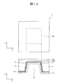
図10における燃料電池用膜電極接合体の構成部材の下層からの並び順も第1実施形態と同じであるが、図10では第1実施形態や図9と異なり、アノード電極20、固体電解質層100、第1の酸素イオンブロッキング層110が基板2の下層に形成され、カソード電極10だけが基板2の上層に形成されている。
図11~図13では、燃料電池用膜電極接合体の構成部材の下層からの並び順が、第1実施形態及び図9~10に示す形態とは異なり、下層からカソード電極10、第1の酸素イオンブロッキング層110、固体電解質層100、アノード電極20の順に形成されている。
図11では、カソード電極10が基板2の下層に形成され、第1の酸素イオンブロッキング層110、固体電解質層100、アノード電極20が基板2の上層に形成されている。図12では、カソード電極10、第1の酸素イオンブロッキング層110が基板2の下層に形成され、固体電解質層100、アノード電極20が基板2の上層に形成されている。図13では、カソード電極10、第1の酸素イオンブロッキング層110、固体電解質層100が基板2の下層に形成され、アノード電極20だけが基板2の上層に形成されている。
図14では、燃料電池用膜電極接合体の構成部材の下層からの並び順が、図11~13と同様に、下層からカソード電極10、第1の酸素イオンブロッキング層、固体電解質層100、アノード電極20の順に形成されているが、第1の酸素イオンブロッキング層の一部110Aが基板2の上表面から形成され、第1の酸素イオンブロッキング層の別の一部110Bが基板2の下表面から形成されている。
燃料電池用膜電極接合体の構成部材の下層からの並び順が、第1実施形態と同じく、下層からアノード電極20、固体電解質層100、第1の酸素イオンブロッキング層、カソード電極10の順に並べて構成した場合にも、第1の酸素イオンブロッキング層を基板2の上層への形成部と基板2の下層への形成部で構成することはもちろん可能である。
また、第1の酸素イオンブロッキング層以外の燃料電池用膜電極接合体の構成部材である、アノード電極20となる第2の金属層、固体電解質層100、カソード電極10となる第1の金属層についても、基板2の上層への形成部と基板2の下層への形成部で構成することが可能である。
第1実施形態と同様に、第1の酸素イオンブロッキング層110を形成する多結晶酸化チタンは、酸素イオン伝導率が低い一方でプロトン伝導率は高い。つまり、酸素イオンとプロトンのうちプロトンだけを選択的に透過させる働きがある。多結晶酸化チタンの他に、酸化ニッケル等の3d遷移金属の酸化物、アルミナ等の多結晶膜も同様の働きがあり、第1の酸素イオンブロッキング層110として用いることができる。
固体電解質層100はYSZ、カソード電極10となる第1の金属層は白金、アノード電極20となる第2の金属層は白金をそれぞれ用いることができるが、第1実施形態の変形例に示した材料をそれぞれに用いることも可能である。
第2実施形態の薄膜プロセス型燃料電池においても、第1実施形態と同様に、酸素イオンブロッキング層110を備えた構造を用いることで、固体電解質層100の内部での水の滞留を抑制し、固体電解質層100のプロトン伝導特性を生かした高効率の発電が実現できる。
(第3実施形態)
第3実施形態に係る燃料電池の構成について図15~16を用いて説明する。
図15に示す燃料電池用膜電極接合体は、下層からアノード電極20、固体電解質層100、第1の酸素イオンブロッキング層110、カソード電極10の順に形成されている点、燃料電池用膜電極接合体が基板2の開口部を完全に覆っている点では第1実施形態と同様であるが、燃料電池用膜電極接合体の全ての構成部材が基板2の上層に形成されている点が異なる。
第3実施形態に係る燃料電池の構成について図15~16を用いて説明する。
図15に示す燃料電池用膜電極接合体は、下層からアノード電極20、固体電解質層100、第1の酸素イオンブロッキング層110、カソード電極10の順に形成されている点、燃料電池用膜電極接合体が基板2の開口部を完全に覆っている点では第1実施形態と同様であるが、燃料電池用膜電極接合体の全ての構成部材が基板2の上層に形成されている点が異なる。
図15のように全ての構成部材を基板2の上層に形成する場合には、下層側の電極(図15ではアノード電極20)と上層側の電極(図15ではカソード電極10)とは上層側で電気的なコンタクトを形成する必要があるので、図15のようにアノード電極20上に固体電解質層100、第1の酸素イオンブロッキング層110、カソード電極10が無い露出領域51を形成する必要がある。
図16に示す燃料電池用膜電極接合体では、図15に示す形態と同様に、下層からアノード電極20、固体電解質層100、第1の酸素イオンブロッキング層110、カソード電極10の順に形成されていて、燃料電池用膜電極接合体の全ての構成部材が基板2の上層に形成されている。しかし、図16では、基板2として導電性の材料であるニッケルを用いており、基板2とアノード電極20とが電気的に接続されている点で異なる。
図16では、アノード電極20との電気的接続は基板2を介して実現できるため、図15のように固体電解質層100、第1の酸素イオンブロッキング層110、カソード電極10が無い露出領域51を形成する必要がなくなる。
下層からカソード電極、酸素イオンブロッキング層、固体電解質層、アノード電極の順に積層する場合にも、それぞれ図15~16と同様に構成することができる。
第1実施形態と同様に、第1の酸素イオンブロッキング層110を形成する多結晶酸化チタンは、酸素イオン伝導率が低い一方でプロトン伝導率は高い。つまり、酸素イオンとプロトンのうちプロトンだけを選択的に透過させる働きがある。多結晶酸化チタンの他に、酸化ニッケル等の3d遷移金属の酸化物、アルミナ等の多結晶膜も同様の働きがあり、第1の酸素イオンブロッキング層110として用いることができる。
固体電解質層100はYSZ、カソード電極10となる第1の金属層は白金、アノード電極20となる第2の金属層は白金をそれぞれ用いることができるが、第1実施形態の変形例に示した材料をそれぞれに用いることも可能である。
第3実施形態の薄膜プロセス型燃料電池においても、第1実施形態と同様に、第1の酸素イオンブロッキング層110を備えた構造を採用することで、固体電解質層100の内部での水の滞留を抑制し、固体電解質層100のプロトン伝導特性を生かした高効率の発電が実現できる。
(第4実施形態)
第4実施形態に係る燃料電池及び燃料電池モジュールの構成について図17~20を用いて説明する。
第1~第3実施形態とは異なり、第4実施形態の燃料電池用膜電極接合体を備えた薄膜プロセス型燃料電池1の全体には、例えば水素を含む燃料ガスと空気等の酸素を含むガスの混合ガスを供給する。アノード電極20とカソード電極10には同じ混合ガスが供給されるが、電極の材料や形状が異なるので電位差が生じ発電する。このような燃料電池をシングルチャンバ型燃料電池と呼ぶ。シングルチャンバ型燃料電池は、燃料ガスを含むガスの系統と、酸素等の酸化剤を含むガスの系統を分離してシールする必要がないため構造が簡単になりシステムコストを低減できるという長所がある。
第4実施形態に係る燃料電池及び燃料電池モジュールの構成について図17~20を用いて説明する。
第1~第3実施形態とは異なり、第4実施形態の燃料電池用膜電極接合体を備えた薄膜プロセス型燃料電池1の全体には、例えば水素を含む燃料ガスと空気等の酸素を含むガスの混合ガスを供給する。アノード電極20とカソード電極10には同じ混合ガスが供給されるが、電極の材料や形状が異なるので電位差が生じ発電する。このような燃料電池をシングルチャンバ型燃料電池と呼ぶ。シングルチャンバ型燃料電池は、燃料ガスを含むガスの系統と、酸素等の酸化剤を含むガスの系統を分離してシールする必要がないため構造が簡単になりシステムコストを低減できるという長所がある。
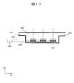
図17は、第4実施形態の薄膜プロセス型SOFCを用いた燃料電池モジュールの構成の一例を示す概略図である。モジュール内に導入するガスは酸素及び水素を含む混合ガスであり、混合ガスは混合ガス導入口301、混合ガス室302、混合ガス排気口303に沿って流れ、燃料電池1におけるアノード電極及びカソード電極が、混合ガスに接触可能に形成されている。図3と同様に、燃料電池1のアノード電極とカソード電極からは導線208が引き出されていて外部負荷209に接続される。燃料電池1は支持基板304上に搭載されている。燃料電池1は1つでも良いが一般には複数個が配置される。
図18は、シングルチャンバ型燃料電池として用いるのに好適な構造を示している。シングルチャンバ型燃料電池の場合、アノード電極20とカソード電極10にはどちらも水素ガスと酸素ガスが供給される。図19に示すように、主にアノード電極20で触媒反応によりプロトンが生成される。生成されたプロトンの一部はその場で酸素イオンと反応し水が生成されるが、残りの一部は固体電解質層100に拡散していく。アノード電極20でのプロトン生成がカソード電極10でのプロトン生成よりも速いため、全体としてプロトンはアノード電極20から、固体電解質層100、第1の酸素イオンブロッキング層110を介してカソード電極10に流れる。カソード電極10で生成した酸素イオンは、第1の酸素イオンブロッキング層110が無いと一部が固体電解質層100に拡散し、固体電解質層100の内部でプロトンと結合して水を生成する。生成した水が滞留し起電力を低下させる。カソード電極10と固体電解質層100の境界に第1の酸素イオンブロッキング層110を形成することにより、カソード電極10からの酸素イオンの拡散を抑制し、固体電解質層100の内部での水の生成を抑制するので、起電力の低下を防止することができる。
第1実施形態と同様に、第1の酸素イオンブロッキング層110を形成する多結晶酸化チタンは、酸素イオン伝導率が低い一方でプロトン伝導率は高い。つまり、酸素イオンとプロトンのうちプロトンだけを選択的に透過させる働きがある。多結晶酸化チタンの他に、酸化ニッケル等の3d遷移金属の酸化物、アルミナ等の多結晶膜も同様の働きがあり、第1の酸素イオンブロッキング層110として用いることができる。
固体電解質層100としてはYSZを用いることができるが、第1実施形態の変形例に示した材料を用いることも可能である。カソード電極10となる第1の金属層を白金、アノード電極20となる第2の金属層を白金とすることができるが、第1実施形態の変形例に示した材料をそれぞれに用いることも可能である。
図18では基板2に開口部50を形成したが、シングルチャンバ型燃料電池の場合、供給ガスはアノード電極20側とカソード電極10側で同じであるため、基板2に開口部50を形成する必要はない。図20は、基板2に開口部を形成せずに、シングルチャンバ型燃料電池用の膜電極接合体を備えた薄膜プロセス型燃料電池を形成した例である。基板2の表面に形成されたカソード電極10上に、第1の酸素イオンブロッキング層110、固体電解質層100、アノード電極20が形成されている。カソード電極10は、給電のために一部で露出している。アノード電極20は、Y方向に延伸するストライプ状に形成されている。開口部を用いない場合、アノード電極20での触媒反応によるプロトン生成はアノード電極20の外縁で最も効率的に起こるため、アノード電極20の周辺長を長くするストライプ状の構造は発電効率の向上に有効である。第3実施形態と同様に基板2を電気伝導体で形成する場合には、カソード電極10と基板2を電気的に接続しカソード電極10への給電を基板2を介して行うことができるので、図20に示したようなカソード電極10の露出部は必要なくなる。
(第5実施形態)
第5実施形態に係る燃料電池の構成について図21~22を用いて説明する。
第1~第4実施形態とは異なり、第5実施形態の燃料電池用膜電極接合体は、アノード電極20、固体電解質層100、第1の酸素イオンブロッキング層110、カソード電極10に加えて、図21に示すように、アノード電極20と固体電解質層100の間に第2の酸素イオンブロッキング層120が形成されている。
第5実施形態に係る燃料電池の構成について図21~22を用いて説明する。
第1~第4実施形態とは異なり、第5実施形態の燃料電池用膜電極接合体は、アノード電極20、固体電解質層100、第1の酸素イオンブロッキング層110、カソード電極10に加えて、図21に示すように、アノード電極20と固体電解質層100の間に第2の酸素イオンブロッキング層120が形成されている。
下層からアノード電極20となる第2の金属層(例えばニッケル)、第2の酸素イオンブロッキング層120(例えば多結晶酸化ニッケル)、固体電解質層100(例えば多結晶YSZ)、第1の酸素イオンブロッキング層110(例えば多結晶酸化チタン)、カソード電極10となる第1の金属層(例えば白金)で構成された燃料電池用膜電極接合体を備えた薄膜プロセス型燃料電池1の全体に、例えば水素を含む燃料ガスと空気等の酸素を含むガスの混合ガスを供給する。アノード電極20とカソード電極10には同じ混合ガスが供給されるが、電極材料が異なるので電位差が生じ発電する。第4実施形態と同様に第5実施形態の燃料電池をシングルチャンバ型燃料電池と呼ぶ。シングルチャンバ型燃料電池は、燃料ガスを含むガスの系統と、酸素等の酸化剤を含むガスの系統を分離してシールする必要がないため構造が簡単になりシステムコストを低減できるという長所がある。
図21はシングルチャンバ型燃料電池に用いるのに好適な第4実施形態とは別の構造を示す。シングルチャンバ型燃料電池の場合、アノード電極20とカソード電極10にはどちらも水素ガスと酸素ガスが供給されるので、図22に示すように、どちらの電極においても触媒反応によりプロトンと酸素イオンが生成される。生成されたプロトンの一部はその場で酸素イオンと反応し水が生成されるが、残りの一部は固体電解質層100に拡散していく。アノード電極20でのプロトン生成がカソード電極10でのプロトン生成よりも速いため、全体としてプロトンはアノード電極20から、第2の酸素イオンブロッキング層120、固体電解質層100、第1の酸素イオンブロッキング層110を介してカソード電極10に流れる。アノード電極20で生成した酸素イオンは、第2の酸素イオンブロッキング層120が無いと一部が固体電解質層100に拡散し、固体電解質層100の内部でプロトンと結合して水を生成する。生成した水が滞留し起電力を低下させる。アノード電極20と固体電解質層100の境界に形成した第2の酸素イオンブロッキング層120が、アノード電極20からの酸素イオンの拡散を抑制し、固体電解質層100の内部での水の生成を抑制するので、起電力の低下を防止することができる。カソード電極10と固体電解質層100の境界に形成する第1の酸素イオンブロッキング層110の役割は、第1~第4実施形態と同様である。
第1実施形態と同様に、第1の酸素イオンブロッキング層110を形成する多結晶酸化チタンは、酸素イオン伝導率が低い一方でプロトン伝導率は高い。つまり、酸素イオンとプロトンのうちプロトンだけを選択的に透過させる働きがある。多結晶酸化チタンの他に、酸化ニッケル等の3d遷移金属の酸化物、アルミナ等の多結晶膜も同様の働きがあり、第1の酸素イオンブロッキング層110として用いることができる。また、第2の酸素イオンブロッキング層120にも第1の酸素イオンブロッキング層110と同じ材料を用いることができる。
固体電解質層100としてはYSZを用いることができるが、第1実施形態の変形例に示した材料を用いることも可能である。
カソード電極10となる第1の金属層は白金、アノード電極20となる第2の金属層はニッケルをそれぞれ用いることができるが、第1実施形態の変形例に示した材料をそれぞれに用いることも可能である。
また、第2及び第3実施形態と同様に、燃料電池用膜電極接合体の構成部材の並び順は上下を逆にすることが可能である。基板2の上層に形成する構成する部材と下層に構成する部材に複数の選択肢があることも同様である。
具体的には、燃料電池用膜電極接合体が下層からアノード電極20、第2の酸素イオンブロッキング層120、固体電解質層100、第1の酸素イオンブロッキング層110、カソード電極10の順に構成される場合、基板2の下層と上層に形成する組み合わせとして、以下のものがある。第1の例は、下層にアノード電極20、上層に第2の酸素イオンブロッキング層120、固体電解質層100、第1の酸素イオンブロッキング層110、カソード電極10である。第2の例は、下層にアノード電極20、第2の酸素イオンブロッキング層120、上層に固体電解質層100、第1の酸素イオンブロッキング層110、カソード電極10である。第3の例は、下層にアノード電極20、第2の酸素イオンブロッキング層120、固体電解質層100、上層に第1の酸素イオンブロッキング層110、カソード電極10である。第4の例は、下層にアノード電極20、第2の酸素イオンブロッキング層120、固体電解質層100、第1の酸素イオンブロッキング層110、上層にカソード電極10である。
燃料電池用膜電極接合体が下層からカソード電極10、第1の酸素イオンブロッキング層110、固体電解質層100、第2の酸素イオンブロッキング層120、アノード電極20の順に構成される場合、基板2の下層と上層に形成する組み合わせとして、以下のものがある。第1の例は、下層にカソード電極10、上層に第1の酸素イオンブロッキング層110、固体電解質層100、第2の酸素イオンブロッキング層120、アノード電極20である。第2の例は、下層にカソード電極10、第1の酸素イオンブロッキング層110、上層に固体電解質層100、第2の酸素イオンブロッキング層120、アノード電極20である。第3の例は、下層にカソード電極10、第1の酸素イオンブロッキング層110、固体電解質層100、上層に第2の酸素イオンブロッキング層120、アノード電極20である。第4の例は、下層にカソード電極10、第1の酸素イオンブロッキング層110、固体電解質層100、第2の酸素イオンブロッキング層120、上層にアノード電極20である。
第3実施形態の図14の第1の酸素イオンブロッキング層と同様に、燃料電池用膜電極接合体の構成部材のどれか1つを基板2の上層から形成する層と基板2の下層から形成する層の両方で形成することも可能である。
また、第5実施形態においても、第4実施形態の図20と同様に基板2の開口部は形成しなくても良い。
第5実施形態の燃料電池用膜電極接合体は、第4実施形態と比較して第2の酸素イオンブロッキング層を形成する必要があるため製造工程数は増加するが、カソード電極10で生成される酸素イオンだけではなくアノード電極20で生成される酸素イオンが固体電解質層に浸入するのを防げるため固体電解質層100中での水の滞留による起電力の低下を抑制する効果が大きい。
第4実施形態の燃料電池用膜電極接合体は、第5実施形態と比較して固体電解質層中での水の滞留による起電力の低下を抑制する効果は劣るものの、少ない製造工程数で効果を得ることができる。
(第6実施形態)
第6実施形態に係る燃料電池の構成について図23~24に基づき説明する。
第6実施形態では、第1~第5実施形態のカソード電極10とアノード電極20を複合材料で形成している。
第6実施形態に係る燃料電池の構成について図23~24に基づき説明する。
第6実施形態では、第1~第5実施形態のカソード電極10とアノード電極20を複合材料で形成している。
第1~第3実施形態の燃料電池用膜電極接合体の変形例として、カソード電極10及びアノード電極20は、例えば図23のように構成することができる。図23におけるカソード電極10は、例えば第1の酸素イオンブロッキング層110に用いる金属酸化物と金属の複合材料で形成することができる。図23ではカソード電極10を白金と酸化チタンの複合材料層MX(Pt,TiOx)で形成している。また、アノード電極20は、固体電解質層100に用いる材料と金属の複合材料で形成することができる。図23ではアノード電極20をYSZとニッケルの複合材料層MX(YSZ,Ni)で形成している。
第6実施形態の燃料電池用膜電極接合体の変形例として、カソード電極10とアノード電極20は、例えば図24のように構成することができる。カソード電極10は、例えば第1の酸素イオンブロッキング層110に用いる金属酸化物と金属の複合材料で形成することができる。図24ではカソード電極10を白金と酸化チタンの複合材料層MX(Pt,TiOx)で形成している。また、アノード電極20は例えば第2の酸素イオンブロッキング層120に用いる金属酸化物と金属の複合材料で形成することができる。図24ではアノード電極20を酸化ニッケルとニッケルの複合材料層MX(NiO,Ni)で形成している。
複合材料の形成は、複合材料と同じ組成のターゲットを用いたスパッタ成膜、それぞれの構成材料のターゲット2つを用いた同時スパッタ成膜等の手法を用いて行うことができる。その他、例えば白金等の酸化しにくい金属と酸化チタンとからなる複合材料層MX(Pt,TiOx)は、白金と金属チタンの複合材料層を形成した後に酸素を含む雰囲気でアニールし酸化することで形成することもできる。
1 燃料電池
2 基板
3 絶縁膜
10 カソード電極
20 アノード電極
50 開口部
51 露出領域
100 固体電解質層
110 第1の酸素イオンブロッキング層
110A 第1の酸素イオンブロッキング層の一部
110B 第1の酸素イオンブロッキング層の別の一部
120 第2の酸素イオンブロッキング層
201 燃料ガス導入口
202 燃料ガス室
203 燃料ガス排気口
204 空気導入口
205 空気室
206 空気排気口
207 遮蔽板
208 導線
209 外部負荷
210 穴
301 混合ガス導入口
302 混合ガス室
303 混合ガス排気口
304 支持基板
MX 複合材料層
2 基板
3 絶縁膜
10 カソード電極
20 アノード電極
50 開口部
51 露出領域
100 固体電解質層
110 第1の酸素イオンブロッキング層
110A 第1の酸素イオンブロッキング層の一部
110B 第1の酸素イオンブロッキング層の別の一部
120 第2の酸素イオンブロッキング層
201 燃料ガス導入口
202 燃料ガス室
203 燃料ガス排気口
204 空気導入口
205 空気室
206 空気排気口
207 遮蔽板
208 導線
209 外部負荷
210 穴
301 混合ガス導入口
302 混合ガス室
303 混合ガス排気口
304 支持基板
MX 複合材料層
Claims (13)
- カソード電極と、
アノード電極と、
前記カソード電極及び前記アノード電極の間に配置される、2価又は3価の正イオンがドーピングされプロトン伝導性を有する多結晶ジルコニア又は多結晶セリアからなる固体電解質層と、
を備え、
前記カソード電極と前記固体電解質層とが、第1の酸素イオンブロッキング層を介して積層される燃料電池。 - 前記固体電解質層が、Y3+、Mg2+、Ca2+及びSc3+からなる群から選択される一種以上の正イオンがドーピングされた多結晶ジルコニアからなる請求項1に記載の燃料電池。
- 前記固体電解質層が、Gd3+及びSm3+からなる群から選択される一種以上の正イオンがドーピングされた多結晶セリアからなる請求項1に記載の燃料電池。
- 前記固体電解質層の厚みが、10nm以上500nm以下である請求項1に記載の燃料電池。
- 前記第1の酸素イオンブロッキング層が、3d遷移金属の酸化物又はアルミナを含む請求項1に記載の燃料電池。
- 前記第1の酸素イオンブロッキング層が、酸化ニッケル又は酸化チタンを含む請求項1に記載の燃料電池。
- 前記アノード電極と前記固体電解質層とが、第2の酸素イオンブロッキング層を介して積層される請求項1に記載の燃料電池。
- 前記第2の酸素イオンブロッキング層が、3d遷移金属の酸化物又はアルミナを含む請求項7に記載の燃料電池。
- 前記第2の酸素イオンブロッキング層が、酸化ニッケル又は酸化チタンを含む請求項7に記載の燃料電池。
- 前記カソード電極が、白金、金、パラジウム、イリジウム、ロジウム、ルテニウム、オスミウム、(La1-xSrx)(Co1-yFey)O3、Sm0.5Sr0.5CoO3、Ba0.8La0.2CoO3、Gd0.5Sr0.5CoO3、(La1-xSrx)MnO3及び(La1-xSrx)FeO3(上記式中、0≦x≦1、0≦y≦1)からなる群から選択される一種以上を含む請求項1に記載の燃料電池。
- 前記アノード電極が、銅又はニッケルがドーピングされた(Ce1-xSmx)O2、銅又はニッケルがドーピングされた(Ce1-xGdx)O2、ニッケルがドーピングされたYSZ、白金、金、パラジウム、イリジウム、ロジウム、ルテニウム及びオスミウム(上記式中、0≦x≦1、0≦y≦1)からなる群から選択される一種以上を含む請求項1に記載の燃料電池。
- 水素を含む燃料ガスが供給される燃料ガス室と、
空気が供給される空気室と、
一以上の請求項1~11のいずれか一項に記載の燃料電池と、
を備え、
前記燃料電池における前記アノード電極が前記燃料ガスに、前記カソード電極が前記空気にそれぞれ接触可能に形成されている燃料電池モジュール。 - 酸素及び水素を含む混合ガスが供給される混合ガス室と、
一以上の請求項1~11のいずれか一項に記載の燃料電池と、
を備え、
前記燃料電池における前記アノード電極及び前記カソード電極が、前記混合ガスに接触可能に形成されている燃料電池モジュール。
Priority Applications (4)
| Application Number | Priority Date | Filing Date | Title |
|---|---|---|---|
| PCT/JP2019/001578 WO2020152731A1 (ja) | 2019-01-21 | 2019-01-21 | 燃料電池セル及び燃料電池モジュール |
| US17/417,832 US20220069327A1 (en) | 2019-01-21 | 2019-01-21 | Fuel battery cell and fuel battery module |
| JP2020567667A JP7181949B2 (ja) | 2019-01-21 | 2019-01-21 | 燃料電池セル及び燃料電池モジュール |
| TW108132169A TWI719623B (zh) | 2019-01-21 | 2019-09-06 | 燃料電池單元及燃料電池模組 |
Applications Claiming Priority (1)
| Application Number | Priority Date | Filing Date | Title |
|---|---|---|---|
| PCT/JP2019/001578 WO2020152731A1 (ja) | 2019-01-21 | 2019-01-21 | 燃料電池セル及び燃料電池モジュール |
Publications (1)
| Publication Number | Publication Date |
|---|---|
| WO2020152731A1 true WO2020152731A1 (ja) | 2020-07-30 |
Family
ID=71736620
Family Applications (1)
| Application Number | Title | Priority Date | Filing Date |
|---|---|---|---|
| PCT/JP2019/001578 Ceased WO2020152731A1 (ja) | 2019-01-21 | 2019-01-21 | 燃料電池セル及び燃料電池モジュール |
Country Status (4)
| Country | Link |
|---|---|
| US (1) | US20220069327A1 (ja) |
| JP (1) | JP7181949B2 (ja) |
| TW (1) | TWI719623B (ja) |
| WO (1) | WO2020152731A1 (ja) |
Cited By (2)
| Publication number | Priority date | Publication date | Assignee | Title |
|---|---|---|---|---|
| JP2022189802A (ja) * | 2021-06-11 | 2022-12-22 | ブルーム エネルギー コーポレイション | 積層されたアノード層及び電解質層を有する固体酸化物形燃料電池及びその製造方法 |
| JP2023155085A (ja) * | 2022-04-08 | 2023-10-20 | 株式会社日立製作所 | 燃料電池および燃料電池スタック |
Citations (5)
| Publication number | Priority date | Publication date | Assignee | Title |
|---|---|---|---|---|
| JP2005222843A (ja) * | 2004-02-06 | 2005-08-18 | Toyota Motor Corp | 燃料電池と燃料電池用電解質膜の製造方法 |
| JP2005243422A (ja) * | 2004-02-26 | 2005-09-08 | Toyota Motor Corp | 燃料電池および燃料電池の製造方法 |
| JP2010251301A (ja) * | 2009-03-23 | 2010-11-04 | Sumitomo Metal Mining Co Ltd | イオン電解質膜構造体とその製造方法およびイオン電解質膜構造体を用いた固体酸化物型燃料電池 |
| US20110262839A1 (en) * | 2010-04-23 | 2011-10-27 | The Board Of Trustees Of The Leland Stanford Jr. University | Proton conducting electrolyte membranes having nano-grain ysz as protective layers, and membrane electrode assemblies and ceramic fuel cells comprising same |
| US8609565B1 (en) * | 2005-04-15 | 2013-12-17 | The Regents Of The University Of California | Low-temperature protonic conduction for hydrogen-related energy applications employing nanostructured functional oxides |
Family Cites Families (8)
| Publication number | Priority date | Publication date | Assignee | Title |
|---|---|---|---|---|
| JP2005327586A (ja) * | 2004-05-14 | 2005-11-24 | Toyota Motor Corp | 燃料電池の製造方法および燃料電池 |
| US7871734B2 (en) * | 2005-08-23 | 2011-01-18 | Massachusetts Institute Of Technology | Micro fuel cell |
| JP2007257937A (ja) * | 2006-03-22 | 2007-10-04 | Sumitomo Electric Ind Ltd | 酸化物イオン伝導率を抑えた多層構造のプロトン伝導体およびそれを用いた構造体 |
| EP2062313A1 (en) * | 2006-09-06 | 2009-05-27 | Ceramic Fuel Cells Limited | A fuel cell gas separator for use between solid oxide fuel cells |
| KR20120040449A (ko) * | 2010-10-19 | 2012-04-27 | 삼성전자주식회사 | 고체산화물 전해질막, 그 제조방법 및 이를 채용한 연료전지 |
| US20140322633A1 (en) * | 2011-12-09 | 2014-10-30 | Posco | Solid oxide fuel cell comprising reaction preventing layer and method for manufacturing same |
| FR3047743B1 (fr) * | 2016-02-16 | 2020-01-17 | Commissariat A L'energie Atomique Et Aux Energies Alternatives | Systeme d'electrolyse de l'eau (soec) ou pile a combustible (sofc) a fonctionnement sous pression dans une enceinte etanche dont la regulation est amelioree |
| US11329303B2 (en) * | 2018-07-19 | 2022-05-10 | Panasonic Intellectual Property Management Co., Ltd. | Fuel cell system and method for operating the same |
-
2019
- 2019-01-21 WO PCT/JP2019/001578 patent/WO2020152731A1/ja not_active Ceased
- 2019-01-21 JP JP2020567667A patent/JP7181949B2/ja active Active
- 2019-01-21 US US17/417,832 patent/US20220069327A1/en active Pending
- 2019-09-06 TW TW108132169A patent/TWI719623B/zh active
Patent Citations (5)
| Publication number | Priority date | Publication date | Assignee | Title |
|---|---|---|---|---|
| JP2005222843A (ja) * | 2004-02-06 | 2005-08-18 | Toyota Motor Corp | 燃料電池と燃料電池用電解質膜の製造方法 |
| JP2005243422A (ja) * | 2004-02-26 | 2005-09-08 | Toyota Motor Corp | 燃料電池および燃料電池の製造方法 |
| US8609565B1 (en) * | 2005-04-15 | 2013-12-17 | The Regents Of The University Of California | Low-temperature protonic conduction for hydrogen-related energy applications employing nanostructured functional oxides |
| JP2010251301A (ja) * | 2009-03-23 | 2010-11-04 | Sumitomo Metal Mining Co Ltd | イオン電解質膜構造体とその製造方法およびイオン電解質膜構造体を用いた固体酸化物型燃料電池 |
| US20110262839A1 (en) * | 2010-04-23 | 2011-10-27 | The Board Of Trustees Of The Leland Stanford Jr. University | Proton conducting electrolyte membranes having nano-grain ysz as protective layers, and membrane electrode assemblies and ceramic fuel cells comprising same |
Non-Patent Citations (1)
| Title |
|---|
| GREGORI ET AL.: "Proton Conduction in Dense and Porous Nanocrystalline Ceria Thin Films", ADVANCED FUNCTIONAL MATERIALS, vol. 23, no. 47, 20 June 2013 (2013-06-20) - 17 December 2013 (2013-12-17), pages 5861 - 5867, XP055727931 * |
Cited By (2)
| Publication number | Priority date | Publication date | Assignee | Title |
|---|---|---|---|---|
| JP2022189802A (ja) * | 2021-06-11 | 2022-12-22 | ブルーム エネルギー コーポレイション | 積層されたアノード層及び電解質層を有する固体酸化物形燃料電池及びその製造方法 |
| JP2023155085A (ja) * | 2022-04-08 | 2023-10-20 | 株式会社日立製作所 | 燃料電池および燃料電池スタック |
Also Published As
| Publication number | Publication date |
|---|---|
| TW202029560A (zh) | 2020-08-01 |
| JP7181949B2 (ja) | 2022-12-01 |
| TWI719623B (zh) | 2021-02-21 |
| US20220069327A1 (en) | 2022-03-03 |
| JPWO2020152731A1 (ja) | 2021-11-04 |
Similar Documents
| Publication | Publication Date | Title |
|---|---|---|
| EP2529442B1 (en) | Phase stable doped zirconia electrolyte compositions with low degradation | |
| US20080254336A1 (en) | Composite anode showing low performance loss with time | |
| JP5652545B2 (ja) | 燃料電池 | |
| JP5655940B2 (ja) | 燃料電池 | |
| US20090011314A1 (en) | Electrode/electrolyte interfaces in solid oxide fuel cells | |
| KR102881977B1 (ko) | 전기분해-내성 공기측 전극을 포함하는 고체 산화물 전해조 전지 | |
| EP3926719A1 (en) | Membrane electrode assembly and fuel cell | |
| JP7181949B2 (ja) | 燃料電池セル及び燃料電池モジュール | |
| US20110053045A1 (en) | Solid oxide fuel cell and method of manufacturing the same | |
| WO2014021446A1 (ja) | 燃料電池 | |
| TWI742877B (zh) | 燃料電池胞、燃料電池系統、燃料電池胞製造方法 | |
| TWI763812B (zh) | 電化學裝置、能源系統、及固態氧化物型燃料電池 | |
| CN103460473B (zh) | 燃料电池 | |
| EP1961067B1 (en) | Fuel cell component having an electrolyte dopant | |
| JP6445988B2 (ja) | 電気化学セルおよび電気化学スタック | |
| JP7668957B2 (ja) | 電気化学セル | |
| JP2010516035A (ja) | 固体酸化物型燃料電池用のカソードの構造 | |
| JP2009087876A (ja) | 単室型燃料電池及び単室型燃料電池積層体 | |
| JP2018010740A (ja) | 電気化学セル、電気化学スタック、および、電気化学セルの製造方法 | |
| WO2012132893A1 (ja) | 燃料電池 | |
| JP2019114532A (ja) | 燃料電池システムのための二次相互接続 |
Legal Events
| Date | Code | Title | Description |
|---|---|---|---|
| 121 | Ep: the epo has been informed by wipo that ep was designated in this application |
Ref document number: 19911459 Country of ref document: EP Kind code of ref document: A1 |
|
| ENP | Entry into the national phase |
Ref document number: 2020567667 Country of ref document: JP Kind code of ref document: A |
|
| NENP | Non-entry into the national phase |
Ref country code: DE |
|
| 122 | Ep: pct application non-entry in european phase |
Ref document number: 19911459 Country of ref document: EP Kind code of ref document: A1 |