WO2020152732A1 - Appareil de détermination d'attention, système de détermination d'attention, procédé de détermination d'attention et programme - Google Patents
Appareil de détermination d'attention, système de détermination d'attention, procédé de détermination d'attention et programme Download PDFInfo
- Publication number
- WO2020152732A1 WO2020152732A1 PCT/JP2019/001586 JP2019001586W WO2020152732A1 WO 2020152732 A1 WO2020152732 A1 WO 2020152732A1 JP 2019001586 W JP2019001586 W JP 2019001586W WO 2020152732 A1 WO2020152732 A1 WO 2020152732A1
- Authority
- WO
- WIPO (PCT)
- Prior art keywords
- pupil
- eyeball
- coordinates
- coordinate
- attention
- Prior art date
- Legal status (The legal status is an assumption and is not a legal conclusion. Google has not performed a legal analysis and makes no representation as to the accuracy of the status listed.)
- Ceased
Links
Images


Classifications
-
- A—HUMAN NECESSITIES
- A61—MEDICAL OR VETERINARY SCIENCE; HYGIENE
- A61B—DIAGNOSIS; SURGERY; IDENTIFICATION
- A61B5/00—Measuring for diagnostic purposes; Identification of persons
- A61B5/16—Devices for psychotechnics; Testing reaction times ; Devices for evaluating the psychological state
- A61B5/163—Devices for psychotechnics; Testing reaction times ; Devices for evaluating the psychological state by tracking eye movement, gaze, or pupil change
-
- A—HUMAN NECESSITIES
- A61—MEDICAL OR VETERINARY SCIENCE; HYGIENE
- A61B—DIAGNOSIS; SURGERY; IDENTIFICATION
- A61B3/00—Apparatus for testing the eyes; Instruments for examining the eyes
- A61B3/02—Subjective types, i.e. testing apparatus requiring the active assistance of the patient
- A61B3/08—Subjective types, i.e. testing apparatus requiring the active assistance of the patient for testing binocular or stereoscopic vision, e.g. strabismus
- A61B3/085—Subjective types, i.e. testing apparatus requiring the active assistance of the patient for testing binocular or stereoscopic vision, e.g. strabismus for testing strabismus
-
- A—HUMAN NECESSITIES
- A61—MEDICAL OR VETERINARY SCIENCE; HYGIENE
- A61B—DIAGNOSIS; SURGERY; IDENTIFICATION
- A61B3/00—Apparatus for testing the eyes; Instruments for examining the eyes
- A61B3/10—Objective types, i.e. instruments for examining the eyes independent of the patients' perceptions or reactions
- A61B3/11—Objective types, i.e. instruments for examining the eyes independent of the patients' perceptions or reactions for measuring interpupillary distance or diameter of pupils
- A61B3/111—Objective types, i.e. instruments for examining the eyes independent of the patients' perceptions or reactions for measuring interpupillary distance or diameter of pupils for measuring interpupillary distance
-
- A—HUMAN NECESSITIES
- A61—MEDICAL OR VETERINARY SCIENCE; HYGIENE
- A61B—DIAGNOSIS; SURGERY; IDENTIFICATION
- A61B3/00—Apparatus for testing the eyes; Instruments for examining the eyes
- A61B3/10—Objective types, i.e. instruments for examining the eyes independent of the patients' perceptions or reactions
- A61B3/113—Objective types, i.e. instruments for examining the eyes independent of the patients' perceptions or reactions for determining or recording eye movement
-
- A—HUMAN NECESSITIES
- A61—MEDICAL OR VETERINARY SCIENCE; HYGIENE
- A61B—DIAGNOSIS; SURGERY; IDENTIFICATION
- A61B3/00—Apparatus for testing the eyes; Instruments for examining the eyes
- A61B3/10—Objective types, i.e. instruments for examining the eyes independent of the patients' perceptions or reactions
- A61B3/14—Arrangements specially adapted for eye photography
-
- A—HUMAN NECESSITIES
- A61—MEDICAL OR VETERINARY SCIENCE; HYGIENE
- A61B—DIAGNOSIS; SURGERY; IDENTIFICATION
- A61B5/00—Measuring for diagnostic purposes; Identification of persons
- A61B5/16—Devices for psychotechnics; Testing reaction times ; Devices for evaluating the psychological state
- A61B5/168—Evaluating attention deficit, hyperactivity
-
- G—PHYSICS
- G06—COMPUTING OR CALCULATING; COUNTING
- G06T—IMAGE DATA PROCESSING OR GENERATION, IN GENERAL
- G06T7/00—Image analysis
- G06T7/70—Determining position or orientation of objects or cameras
-
- G—PHYSICS
- G06—COMPUTING OR CALCULATING; COUNTING
- G06V—IMAGE OR VIDEO RECOGNITION OR UNDERSTANDING
- G06V40/00—Recognition of biometric, human-related or animal-related patterns in image or video data
- G06V40/10—Human or animal bodies, e.g. vehicle occupants or pedestrians; Body parts, e.g. hands
- G06V40/16—Human faces, e.g. facial parts, sketches or expressions
- G06V40/161—Detection; Localisation; Normalisation
-
- G—PHYSICS
- G06—COMPUTING OR CALCULATING; COUNTING
- G06V—IMAGE OR VIDEO RECOGNITION OR UNDERSTANDING
- G06V40/00—Recognition of biometric, human-related or animal-related patterns in image or video data
- G06V40/10—Human or animal bodies, e.g. vehicle occupants or pedestrians; Body parts, e.g. hands
- G06V40/18—Eye characteristics, e.g. of the iris
-
- G—PHYSICS
- G06—COMPUTING OR CALCULATING; COUNTING
- G06T—IMAGE DATA PROCESSING OR GENERATION, IN GENERAL
- G06T2207/00—Indexing scheme for image analysis or image enhancement
- G06T2207/30—Subject of image; Context of image processing
- G06T2207/30004—Biomedical image processing
- G06T2207/30041—Eye; Retina; Ophthalmic
Definitions
- the present invention relates to an attention determination device, an attention determination system, an attention determination method, and a program.
- An information presentation device has been proposed that detects jumping eye movements from a face image of a person and determines the attention level (also simply referred to as “attention”) of the person based on the occurrence frequency of the detected jumping eye movements.
- attention level also simply referred to as “attention”
- the information presentation device described in Patent Document 1 detects a saccade, which is a high-speed eye movement, and determines the attention level of the operator based on the frequency of occurrence of the detected saccade.
- a camera capable of shooting at a high frame rate is required to shoot a high-speed eye movement such as saccade. As a result, the cost of the information presentation device increases.
- the present invention has been made to solve the above-mentioned problem, and an object thereof is to determine the attention of a person using an image shot at a low frame rate.
- a attention determination device that uses a captured image of a first eyeball and a second eyeball of a person, The first reference coordinates for the first eyeball and the second reference coordinates for the second eyeball are set in the captured image, and the coordinates of the pupil of the first eyeball in the image are set. And a second pupil coordinate, which is a coordinate in the image of the first pupil coordinate and the pupil of the second eyeball, is calculated, and the first reference coordinate, the second reference coordinate, and the first reference coordinate are calculated.
- An image processing unit that outputs the pupil coordinates and the second pupil coordinates;
- a pupil distance calculation unit that calculates at least one position component of the first pupil coordinates with respect to the first reference coordinates and at least one position component of the second pupil coordinates with respect to the second reference coordinates;
- Oblique detection result indicating the state of the first eyeball and the second eyeball by using the at least one position component of the first pupil coordinate and the at least one position component of the second pupil coordinate
- An eccentricity detector that outputs
- an attention determination unit that determines the attention of the person according to the result of the phoria detection.
- a attention determination device that uses a captured image of a first eyeball and a second eyeball of a person, The first reference coordinates for the first eyeball and the second reference coordinates for the second eyeball are set in the captured image, and the coordinates of the pupil of the first eyeball in the image are set.
- a second pupil coordinate which is a coordinate in the image of the first pupil coordinate and the pupil of the second eyeball is calculated, and the first reference coordinate, the second reference coordinate, and the first reference coordinate
- An image processing unit that outputs the pupil coordinates and the second pupil coordinates;
- a pupil distance calculation unit that calculates at least one position component of the first pupil coordinates with respect to the first reference coordinates and at least one position component of the second pupil coordinates with respect to the second reference coordinates;
- a pupil distance correction unit that normalizes the at least one position component of the first pupil coordinates and the at least one position component of the second pupil coordinates, and outputs a normalized value as a pupil distance correction value;
- An oblique position detection unit that outputs an oblique position detection result indicating the states of the first eyeball and the second eyeball using the pupil distance correction value, And an attention determination unit that determines the attention of the person according to the result of the oblique detection.
- An attention determination system includes the attention determination device.
- a attention determination method for determining the attention of a person using a captured image including a first eyeball and a second eyeball of the person, Setting a first reference coordinate for the first eyeball and a second reference coordinate for the second eyeball in the captured image, Calculating a first pupil coordinate that is a coordinate of the pupil of the first eyeball in the captured image and a second pupil coordinate that is a coordinate of the pupil of the second eyeball in the captured image, Outputting the first reference coordinates, the second reference coordinates, the first pupil coordinates, and the second pupil coordinates, Calculating at least one position component of the first pupil coordinates with respect to the first reference coordinates and at least one position component of the second pupil coordinates with respect to the second reference coordinates; Oblique detection result indicating the state of the first eyeball and the second eyeball by using the at least one position component of the first pupil coordinate and the at least one position component of the second pupil coordinate And output The attention of the person is determined according to the result of the oblique detection.
- a attention determination method for determining the attention of a person using a captured image including a first eyeball and a second eyeball of the person, Setting a first reference coordinate for the first eyeball and a second reference coordinate for the second eyeball in the captured image, Calculating a first pupil coordinate that is a coordinate of the pupil of the first eyeball in the captured image and a second pupil coordinate that is a coordinate of the pupil of the second eyeball in the captured image, Outputting the first reference coordinates, the second reference coordinates, the first pupil coordinates, and the second pupil coordinates, Calculating at least one position component of the first pupil coordinates with respect to the first reference coordinates and at least one position component of the second pupil coordinates with respect to the second reference coordinates; Normalizing the at least one position component of the first pupil coordinates and the at least one position component of the second pupil coordinates, Output the normalized value as the pupil distance correction value, Outputting a phoria detection result indicating the states of the first eyeball and the second eyeball
- a program is A program for causing a computer to execute an attention determination method for determining the attention of a person using a captured image including a first eyeball and a second eyeball of a person, Setting a first reference coordinate for the first eyeball and a second reference coordinate for the second eyeball in the captured image, Calculating a first pupil coordinate that is a coordinate of the pupil of the first eyeball in the captured image and a second pupil coordinate that is a coordinate of the pupil of the second eyeball in the captured image, Outputting the first reference coordinates, the second reference coordinates, the first pupil coordinates, and the second pupil coordinates, Calculating at least one position component of the first pupil coordinates with respect to the first reference coordinates and at least one position component of the second pupil coordinates with respect to the second reference coordinates; Oblique detection result indicating the state of the first eyeball and the second eyeball by using the at least one position component of the first pupil coordinate and the at least one position component of the second pupil coordinate And output The attention of the person is determined according to the
- a program is A program for causing a computer to execute an attention determination method for determining the attention of a person using a captured image including a first eyeball and a second eyeball of a person, Setting a first reference coordinate for the first eyeball and a second reference coordinate for the second eyeball in the captured image, Calculating a first pupil coordinate that is a coordinate of the pupil of the first eyeball in the captured image and a second pupil coordinate that is a coordinate of the pupil of the second eyeball in the captured image, Outputting the first reference coordinates, the second reference coordinates, the first pupil coordinates, and the second pupil coordinates, Calculating at least one position component of the first pupil coordinates with respect to the first reference coordinates and at least one position component of the second pupil coordinates with respect to the second reference coordinates; Normalizing the at least one position component of the first pupil coordinates and the at least one position component of the second pupil coordinates, Output the normalized value as the pupil distance correction value, Outputting a phoria detection result indicating the states
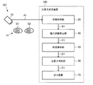
- FIG. 6 It is a block diagram which shows roughly the structure of the attention determination system which concerns on Embodiment 1 of this invention.
- 6 is a flowchart showing an example of steps of the attention determination method according to the first embodiment. It is a figure which shows the corresponding relationship between the position of a 1st eyeball of a person, a 2nd eyeball, and a nose, and the position of these elements in a picked-up image. It is a figure which shows the calculation method of a pupil distance.
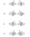
- (A) to (D) are diagrams showing examples of eye movements of both eyes of a person.
- (A) to (D) are diagrams showing an example of an eye movement of one eye of a person, specifically, an oblique state.
- FIG. 1 is a figure which shows an example of the hardware constitutions of an attention determination device
- FIG. 1 is a figure which shows another example of the hardware constitutions of the attention determination device 100. It is a block diagram which shows roughly the structure of the attention determination system which concerns on Embodiment 2 of this invention. 9 is a flowchart showing an example of steps of the attention determination method according to the second embodiment.
- FIG. 1 is a block diagram schematically showing the configuration of an attention determination system 101 according to the first embodiment of the present invention.
- the attention determination system 101 includes the image capturing unit 10 and the attention determination device 100 that uses an image including the first eyeball S1 and the second eyeball S2 of the person H captured by the image capturing unit 10.
- the attention determination device 100 includes an image processing unit 20, a pupil distance calculation unit 30, an oblique position detection unit 40, and an attention determination unit 50.
- the attention determination device 100 determines the attention of the person H using the image including the first eyeball S1 and the second eyeball S2.
- the attention determination device 100 may further include an output device 70.
- the image captured by the image capturing unit 10 is, for example, an image including the face of the person H.
- the image capturing unit 10 captures an image including at least the first eyeball S1 and the second eyeball S2 of the person H. That is, the image including the face of the person H captured by the image capturing unit 10 is an image including at least the first eyeball S1 and the second eyeball S2 of the person H.
- the first eyeball S1 is the right eye of the person H
- the second eyeball S2 is the left eye of the person H.
- the image captured by the image capturing unit 10 may be a still image or a moving image.
- the imaging unit 10 captures an image including the first eyeball S1, the second eyeball S2, and the nose S3 of the person H.
- the image including the face of the person H captured by the image capturing unit 10 is an image including the first eyeball S1, the second eyeball S2, and the nose S3 of the person H.
- the first eyeball S1 and the second eyeball S2 are targets determined by the attention determination unit 50.
- the image captured by the image capturing unit 10 is referred to as “captured image A1”.
- the imaging unit 10 outputs the captured image A1.
- the imaging unit 10 periodically or continuously shoots an image including the face of the person H, and periodically or continuously outputs the shot image A1.
- the image capturing unit 10 may have a memory that stores the captured image A1.
- the imaging unit 10 can store the captured image A1 in the memory and can output the captured image A1 stored in the memory.
- the captured image A1 output from the image capturing unit 10 is input to the image processing unit 20.
- FIG. 2 is a flowchart showing an example of steps of the attention determination method for determining the attention of the person H in the attention determination system 101 described above.
- step ST1 the first reference coordinate for the first eyeball S1 and the second reference coordinate for the second eyeball S2 are set in the captured image A1.
- step ST2 the first pupil coordinates that are the coordinates of the pupil 24 of the first eyeball S1 (also referred to as the first pupil or the right pupil) in the captured image A1 and the pupil 25 of the second eyeball S2 (second pupil).
- the second pupil coordinates which are the coordinates of the pupil or the left pupil) in the captured image A1, are calculated.
- step ST3 the first reference coordinates, the second reference coordinates, the first pupil coordinates, and the second pupil coordinates are output.
- At step ST4 at least one position component of the first pupil coordinates with respect to the first reference coordinates and at least one position component of the second pupil coordinates with respect to the second reference coordinates are calculated.
- step ST5 an oblique position detection result indicating the states of the first eyeball S1 and the second eyeball S2 using at least one position component of the first pupil coordinates and at least one position component of the second pupil coordinates. Is output.
- step ST6 the attention of the person H is judged according to the result of the oblique detection.
- step ST7 the attention state E1 is output.
- the image processing unit 20 acquires the captured image A1.
- the image processing unit 20 uses the captured image A1 to generate output coordinates B1 and outputs the generated output coordinates B1.
- the output coordinate B1 is data including at least one coordinate calculated by the image processing unit 20.
- the output coordinate B1 includes, for example, at least one reference coordinate, a first pupil coordinate Re (also referred to as right pupil coordinate), and a second pupil coordinate Le (also referred to as left pupil coordinate).
- the output coordinates B1 may further include other coordinates such as the nose coordinates Nt.
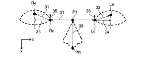
- FIG. 3 is a diagram showing a correspondence relationship between the positions of the first eyeball S1, the second eyeball S2, and the nose S3 of the person H and the positions of these elements in the captured image A1.
- the x-axis direction indicates the lateral direction in the captured image A1
- the y-axis direction is the direction orthogonal to the x-axis direction in the captured image A1. , That is, the vertical direction.
- the image processing unit 20 sets at least one reference coordinate in the captured image (that is, the captured image A1).
- the reference coordinates for the first eyeball S1 also referred to as the first reference coordinates
- the reference coordinates for the second eyeball S2 also referred to as the second reference coordinates
- the image processing unit 20 selects the coordinates of the inner canthus 26 of the first eyeball S1 as the reference coordinates for the first eyeball S1, and sets the reference coordinates for the first eyeball S1 as the first inner canthus. Set to coordinate Rc. Similarly, the image processing unit 20 selects the coordinates of the inner canthus 27 of the second eyeball S2 as the reference coordinates for the second eyeball S2, and sets the reference coordinates for the second eyeball S2 as the second inner canthus coordinates Lc. Set.
- the first inner canthus coordinates Rc are used as the reference coordinates for the first eyeball S1, but other coordinates may be used as the reference coordinates for the first eyeball S1.
- the second inner canthus coordinate Lc is used as the reference coordinate for the second eyeball S2, other coordinates may be used as the reference coordinate for the second eyeball S2.
- the same coordinates may be used as the reference coordinates for the first eyeball S1 and the second eyeball S2.
- the first inner canthus coordinates Rc are coordinates in the photographed image A1 of the inner canthus 26 of the first eyeball S1
- the second inner canthus coordinates Lc are coordinates in the photographed image A1 of the inner canthus 27 of the second eyeball S2. is there.
- the first inner corner coordinate Rc is represented by, for example, coordinates (Rcx, Rcy), and the second inner corner coordinate Lc is represented by, for example, coordinates (Lcx, Lcy).
- Rcx indicates the x coordinate of the inner canthus 26, that is, the position of the inner canthus 26 on the x axis.
- Rcy indicates the y coordinate of the inner canthus 26, that is, the position of the inner canthus 26 on the y-axis.
- Lcx indicates the x coordinate of the inner canthus 27, that is, the position of the inner canthus 27 on the x axis.
- Lcy indicates the y coordinate of the inner corner of the eye 27, that is, the position of the inner corner of the eye 27 on the y axis.
- the image processing unit 20 calculates the first pupil coordinate Re and the second pupil coordinate Le.
- the first pupil coordinate Re is a coordinate of the pupil 24 of the first eyeball S1 in the captured image A1.
- the second pupil coordinate Le is the coordinate of the pupil 25 of the second eyeball S2 in the captured image A1.
- the nose coordinates Nt are the coordinates of the nose tip 28 of the nose S3 in the captured image A1.
- the nose tip 28 is the tip of the nose S3 in the y-axis direction.
- the first pupil coordinate Re is represented by, for example, coordinates (Rex, Rey)
- the second pupil coordinate Le is represented by, for example, coordinates (Lex, Ley)
- the nose coordinate Nt is represented by, for example, coordinates (Ntx).
- Rex indicates the x coordinate of the pupil 24, that is, the position of the pupil 24 on the x axis.
- Rey indicates the y coordinate of the pupil 24, that is, the position of the pupil 24 on the y axis.
- Lex indicates the x coordinate of the pupil 25, that is, the position of the pupil 25 on the x axis.
- Ley indicates the y coordinate of the pupil 25, that is, the position of the pupil 25 on the y axis.
- Ntx indicates the x coordinate of the nose tip 28, that is, the position of the nose tip 28 on the x axis.
- Nty indicates the y coordinate of the nose tip 28, that is, the position of the nose tip 28 on the y axis.
- step ST3 the image processing unit 20 outputs at least one pupil coordinate and at least one reference coordinate as the output coordinate B1.
- the image processing unit 20 outputs the first pupil coordinate Re, the second pupil coordinate Le, the first reference coordinate, and the second reference coordinate.
- the image processing unit 20 when the image processing unit 20 sets the first inner canthus coordinates Rc as the first reference coordinates and the second inner canthus coordinates Lc as the second reference coordinates, the image processing unit 20 makes the first pupil coordinates.
- Re the second pupil coordinate Le
- the first inner canthus coordinate Rc and the second inner canthus coordinate Lc are output as the output coordinate B1.
- FIG. 4 is a diagram showing a method of calculating the pupil distance.
- the output coordinate B1 is input to the pupil distance calculation unit 30.
- the pupil distance calculation unit 30 uses the output coordinates B1 to calculate a pupil distance 31 (also referred to as a first pupil distance), a pupil distance 32 (also referred to as a second pupil distance), and a pupil distance 33 (also referred to as a third pupil distance).
- the pupil distance 34 also referred to as the fourth pupil distance
- the pupil distance 35 also referred to as the fifth pupil distance
- the pupil distance 36 also referred to as the sixth pupil distance
- the pupil distance calculation unit 30 periodically calculates the pupil distances 31, 32, 33, 34, 35, and 36. As a result, the pupil distance calculation unit 30 calculates the time series data.
- the pupil distance calculation unit 30 determines at least one position component of the first pupil coordinates Re with respect to the first reference coordinates in the captured image A1 and the second reference coordinates with respect to the second reference coordinates in the captured image A1. And at least one position component of the pupil coordinate Le of the above are periodically calculated.
- the position component of the first pupil coordinate Re is the pupil distances 31, 33, and 35
- the position component of the second pupil coordinate Le is the pupil distances 32, 34, and 36.
- the pupil distance 31 is the distance from the first reference position to the pupil 24.
- the pupillary distance 31 is the distance from the first inner corner coordinate Rc as the first reference coordinate to the first pupilal coordinate Re.
- the distance from the first inner canthus coordinate Rc to the first pupil coordinate Re in the captured image A1 is R.
- the pupil distance 32 is the distance from the second reference position to the pupil 25.
- the pupil distance 32 is the distance from the second inner canthus coordinate Lc serving as the second reference coordinate to the second pupil coordinate Le.
- the distance from the second inner canthus coordinate Lc to the second pupil coordinate Le in the captured image A1 is L.
- the pupil distance 33 is the distance from the first reference position in the lateral direction to the pupil 24.
- the pupil distance 33 is the distance from the first inner corner coordinate Rc as the first reference coordinate in the lateral direction in the captured image A1 to the first pupil coordinate Re.
- the distance from the first inner canthus coordinate Rc to the first pupil coordinate Re in the lateral direction within the captured image A1 is Rh.
- the pupil distance 34 is the distance from the second reference position in the lateral direction to the pupil 25.
- the pupil distance 34 is the distance from the second inner corner coordinate Lc as the second reference coordinate in the lateral direction in the captured image A1 to the second pupil coordinate Le.
- the distance from the second inner canthus coordinate Lc to the second pupil coordinate Le in the lateral direction within the captured image A1 is Lh.
- the pupil distance 35 is the distance from the first reference position to the pupil 24 in the vertical direction.
- the pupil distance 35 is the distance from the first inner corner coordinate Rc as the first reference coordinate in the vertical direction in the photographed image A1 to the first pupil coordinate Re.
- the distance from the first inner canthus coordinate Rc to the first pupil coordinate Re in the vertical direction in the captured image A1 is Rv.
- the pupil distance 36 is the distance from the second reference position to the pupil 25 in the vertical direction.
- the pupil distance 36 is the distance from the second inner corner coordinate Lc as the second reference coordinate in the longitudinal direction in the photographed image A1 to the second pupil coordinate Le.
- the distance from the second inner canthus coordinate Lc to the second pupil coordinate Le in the vertical direction in the captured image A1 is Lv.
- the distance Rh is represented by
- Lh is represented by
- Rv is represented by
- the distance R is represented by the equation (1) using the distance Rh and the distance Rv
- the distance L is represented by the equation (2) using the distance Lh and the distance Lv. ...(1) ...(2)
- the pupil distance calculation unit 30 outputs the calculated distances Rh, Lh, Rv, Lv, R, and L as the pupil distance output C1.
- the pupil distance output C1 is input to the phoria detection unit 40.
- the oblique position detection unit 40 detects a change in the position of the pupil 24 during a predetermined period using at least one position component of the first pupil coordinate Re and at least one position component of the second pupil coordinate Le. A change in the position of the pupil 25 is calculated. Further, the oblique position detection unit 40 determines the eye movement of the person H by using the calculation result of the fluctuation of the position of the pupil 24 and the fluctuation of the position of the pupil 25.
- the phoria detection unit 40 determines the eye movement of the person H by using the fluctuation of the component of the pupil distance output C1 as the time series data.
- the components of the pupil distance output C1 are the distances Rh, Lh, Rv, Lv, R, and L.
- the phoria detection unit 40 uses the fluctuation of the component of the pupil distance output C1 to determine whether the state of both eyes of the person H is the eye movement of both eyes of the person H (also referred to as binocular movement state). It is determined whether the eye movement of one eye (for example, an oblique position). For example, when both the variation of the position of the pupil 24 and the variation of the position of the pupil 25 are equal to or more than the threshold value or less than the threshold value, the oblique position detecting unit 40 determines that the state of both eyes of the person H is the binocular movement state. To do.
- the oblique position detection unit 40 determines whether one of the first eyeball S1 and the second eyeball S2. Is an oblique position (that is, eye position shift).
- the threshold value used by the oblique position detection unit 40 may be one threshold value or two or more threshold values.
- the fluctuation of the component of the pupil distance output C1 is indicated by, for example, the variance.
- the phoria detection unit 40 determines whether it is the binocular movement state or the phoria state, the attention of the person H can be determined according to the determination result.
- FIG. 5A shows a fixation state.
- the fixation state is a state in which the left and right eyes are fixed, and the person H is gazing at the visual target.
- FIG. 5B is a diagram showing a line-of-sight movement state in the lateral direction. For example, when the distance Rh increases and the distance Lh decreases, it is determined that the line of sight of the person H is facing right. On the other hand, when the distance Rh decreases and the distance Lh increases, it is determined that the line of sight of the person H is facing left.
- FIG. 5C is a diagram showing a line-of-sight movement state in the vertical direction. For example, when the distance Rv and the distance Lv increase, it is determined that the line of sight of the person H is facing upward. On the other hand, when the distance Rv and the distance Lv increase, it is determined that the line of sight of the person H is facing downward. When the distance R and the distance L increase, it is determined that the line of sight of the person H is oblique.
- FIG. 5D is a diagram showing a vergence movement state.
- the vergence movement is a movement to bring both eyes to the nose side. That is, the vergence movement state is a state in which both eyes of the person H are performing vergence movement. For example, when the distance Rh and the distance Lh decrease, the state of both eyes of the person H is determined to be the vergence movement state.
- the eye movements of both eyes of the person H are not limited to the examples shown in FIGS. 5(A) to 5(D). For example, when the distance Rh and the distance Lh increase, it is determined that both eyes of the person H are performing divergence movement. Divergent movement is a movement to bring both eyes closer to the ear.
- FIG. 6A to FIG. 6D are diagrams showing an example of the eye movement of one eye of the person H, specifically, an oblique state.
- the human eye position includes, for example, a binocular eye position, a fusion-free position, a physiological rest position, and an absolute rest position.
- the binocular position the external and internal ocular muscles are strained to exert the binocular visual function.
- the fusion-removing eye position removes the fusional convergence for fusing the images input to the left and right eyes.
- Physiological rest is seen, for example, during deep sleep and results in minimal ocular muscle stimulation.
- Absolute rest position is seen, for example, after death and the ocular muscles are released from any irritation.
- the oblique position usually has a binocular visual function by tensioning the ocular muscles, but it potentially has a fusion removal eye position, and when the ocular muscles become insufficiently tensioned. It is a state of temporarily approaching the fusion-removed eye position. When the fusional vergence is lost from the state where the binocular vision function is working, the eye position shifts as an oblique position in one eye, and the direction of the line of sight varies from person to person.
- the eccentricity detection unit 40 determines that the person H (that is, the first value). It is possible to determine that the eyeball S1 and the second eyeball S2) are in one of the oblique positions shown in FIGS. 6(A) to 6(D).
- FIG. 6(A) shows an external oblique state.
- the external oblique state is a state in which one of the pupil of the first eyeball S1 and the pupil of the second eyeball S2 is closer to the ear side.
- the distance Rh is constant and the distance Lh increases, it is determined that the first eyeball S1 and the second eyeball S2 are in the external oblique position.
- the distance Rh increases and the distance Lh is constant, it is determined that the first eyeball S1 and the second eyeball S2 are in the external oblique position.
- FIG. 6(B) shows the internal oblique position.
- the inner oblique state is a state in which one of the pupil of the first eyeball S1 and the pupil of the second eyeball S2 is near the nose side.
- the first eyeball S1 and the second eyeball S2 are determined to be in the internal oblique position.
- the distance Rh decreases and the distance Lh is constant, it is determined that the first eyeball S1 and the second eyeball S2 are in the internal oblique position.
- FIG. 6C shows the upper oblique position.
- the upper oblique state is a state in which one of the pupil of the first eyeball S1 and the pupil of the second eyeball S2 is located on the upper side.
- the distance Rv is constant and the distance Lv increases, it is determined that the first eyeball S1 and the second eyeball S2 are in the upper oblique position.
- the distance Rv increases and the distance Lv is constant, the first eyeball S1 and the second eyeball S2 are determined to be in the upper oblique position.
- FIG. 6(D) shows the downward oblique position.
- the downward oblique state is a state in which one of the pupil of the first eyeball S1 and the pupil of the second eyeball S2 is leaning downward.
- the first eyeball S1 and the second eyeball S2 are determined to be in the downward oblique position.
- the distance Rv decreases and the distance Lv is constant, it is determined that the first eyeball S1 and the second eyeball S2 are in the downward oblique position.
- the oblique position is not limited to the example shown in FIGS. 6(A) to 6(D).
- the first eyeball S1 and the second eyeball S2 are inclined obliquely. It is judged that it is a rank.
- the phoria detection unit 40 uses, for example, time-series data, the variance values ⁇ rh, ⁇ lh, and ⁇ lh of each component included in the pupil distance output C1. Calculate ⁇ rv, ⁇ lv, ⁇ r, and ⁇ l.
- the time-series data is the pupillary distance output C1 that is periodically input to the phoria detection unit 40.
- the variance value ⁇ rh is a variance value of the distance Rh input to the eccentricity detection unit 40 within a predetermined period.
- the variance value ⁇ lh is the variance value of the distance Lh input to the phoria detection unit 40 within a predetermined period.
- the variance value ⁇ rv is a variance value of the distance Rv input to the phoria detector 40 within a predetermined period.
- the variance value ⁇ lv is a variance value of the distance Lv input to the phoria detector 40 within a predetermined period.
- the variance value ⁇ r is a variance value of the distance R input to the oblique position detection unit 40 within a predetermined period.
- the variance value ⁇ l is the variance value of the distance L input to the oblique position detection unit 40 within a predetermined period.
- the eccentricity detection unit 40 compares the variance value of each component with a predetermined threshold value (also referred to as “variation threshold value”) corresponding to the variance value.
- the threshold value corresponding to the variance value ⁇ rh is the threshold value Trh.
- the threshold value corresponding to the variance value ⁇ lh is the threshold value Tlh.
- the threshold value corresponding to the variance value ⁇ rv is the threshold value Trv.
- the threshold value corresponding to the variance value ⁇ lv is the threshold value Tlv.
- the threshold value corresponding to the variance value ⁇ r is the threshold value Tr.
- the threshold value corresponding to the variance value ⁇ l is the threshold value Tl.
- Each of the thresholds Trh, Tlh, Trv, Tlv, Tr, and Tl is a predetermined value.
- a variance value of each component included in the pupillary distance output C1 in a predetermined period may be used as each threshold value, and a value obtained by weighting the variance value obtained from the time series data in the fixation state. May be used.
- the phoria detection unit 40 determines whether the data regarding the first eyeball S1 satisfies the first condition (that is, ⁇ rh ⁇ Trh, ⁇ rv ⁇ Trv, and ⁇ r ⁇ Tr), and regarding the second eyeball S2. Of the data satisfies the second condition (that is, ⁇ lh ⁇ Tlh, ⁇ lv ⁇ Tlv, and ⁇ l ⁇ Tl).
- the oblique position detection unit 40 determines that the first eyeball S1 of the person H is in the fixation state.
- the oblique position detection unit 40 determines that the first eyeball S1 of the person H is not in the fixation state. That is, the oblique position detection unit 40 determines that the first eyeball S1 is moving in either direction.
- the oblique position detection unit 40 determines that the second eyeball S2 of the person H is in the fixation state.
- the oblique position detection unit 40 determines that the first eyeball S1 of the person H is not in the fixation state. That is, the oblique position detection unit 40 determines that the second eyeball S2 is moving in either direction.
- the phoria detection unit 40 determines that the first eyeball S1 and the second eyeball S2 are , It is determined that binocular movements such as vertical line-of-sight movement, horizontal line-of-sight movement, vergence movement, or divergence movement are being performed. In other words, when the data regarding the first eyeball S1 and the second eyeball S2 does not satisfy both the first condition and the second condition, the phoria detection unit 40 determines that the first eyeball S1 and the second eyeball S2 It is determined that the state of the eyeball S2 is the binocular movement state.
- the phoria detection unit 40 shifts the eye position of the person H in one eye. Is determined to have occurred. In this case, the oblique position detecting unit 40 determines that the person H is in the oblique position. In other words, the oblique position detection unit 40 determines that one of the first eyeball S1 and the second eyeball S2 is in the oblique position.
- the first eyeball S1 and the second eyeball S2 are in the both eye movement state, or one of the first eyeball S1 and the second eyeball S2 is in the oblique state. Can be determined.
- the phoria detection unit 40 determines whether the first eyeball S1 and the second eyeball S2 are in both eye movement states, or whether one of the first eyeball S1 and the second eyeball S2 is in the phoria state. All you have to do is judge.
- the above-described determination method in the oblique position detection unit 40 is an example, and various determination conditions may be combined.
- the phoria detection unit 40 outputs the determination result as the phoria detection result D1.
- the oblique position detection result D1 indicates the states of the first eyeball S1 and the second eyeball S2.
- the phoria detection result D1 indicates that the first eyeball S1 and the second eyeball S2 are in both eye movement states, or one of the first eyeball S1 and the second eyeball S2 is in the phoria state. Indicates if there is.
- the oblique detection result D1 is input to the attention determination unit 50.
- the attention determination unit 50 determines the attention of the person H according to the oblique detection result D1 and generates the determination result as the attention state E1.
- the attention state E1 is, for example, a reduced attention state or a maintained attention state.
- the state of reduced attention is a state in which the person H has low attention
- the state of maintained attention is a state in which the person H has high attention.
- the attention determination unit 50 determines that the person H is in the attention maintaining state and sets the attention state E1 which is a signal indicating the attention maintaining state. To generate.
- the attention determination unit 50 determines that the person H is in the attention reduced state and generates the attention state E1 which is a signal indicating the attention reduced state. To do.
- the attention determination unit 50 outputs the attention state E1.
- the attention state E1 is input to the output device 70 such as a monitor, a head-up display, a speaker, or a vibrator.
- the output device 70 outputs, for example, at least one of an image (for example, a still image or a moving image), a sound, and a vibration according to the attention state E1.
- the output device 70 may not output anything.
- FIG. 7A is a diagram showing an example of the hardware configuration of the attention determination device 100.
- FIG. 7B is a diagram showing another example of the hardware configuration of the attention determination device 100.
- the attention determination device 100 includes, for example, at least one processor 108a and at least one memory 108b.
- the processor 108a is, for example, a Central Processing Unit (CPU) that executes a program stored in the memory 108b.
- the function of the attention determination device 100 is realized by software, firmware, or a combination of software and firmware.
- Software and firmware can be stored in the memory 108b as programs. Thereby, the program for realizing the function of the attention determination device 100 (for example, the attention determination method described in the present embodiment) is executed by the computer.
- the memory 108b is a computer-readable recording medium, for example, a volatile memory such as a RAM (Random Access Memory) and a ROM (Read Only Memory), a nonvolatile memory, or a combination of a volatile memory and a nonvolatile memory. Is.
- a volatile memory such as a RAM (Random Access Memory) and a ROM (Read Only Memory)
- ROM Read Only Memory
- nonvolatile memory or a combination of a volatile memory and a nonvolatile memory. Is.
- the attention determination device 100 may be configured with a processing circuit 108c as dedicated hardware such as a single circuit or a composite circuit. In this case, the function of the attention determination device 100 is realized by the processing circuit 108c.
- the attention determination device 100 detects whether or not the eye position shift in the person H has occurred. Therefore, the attention determination device 100 can determine attention using the image captured at the low frame rate. As a result, the attention determination device 100 does not require a high processing capability of the CPU as compared with a device that detects a saccade, which is a high-speed eye movement. As a result, the manufacturing cost of the attention determination device 100 can be reduced.
- the attention determination system 101 includes an attention determination device 100. Therefore, the attention determination system 101 has the same advantages as the attention determination device 100 described above.
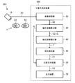
- FIG. 8 is a block diagram schematically showing the configuration of the attention determination system 201 according to Embodiment 2 of the present invention.
- FIG. 9 is a flowchart showing an example of steps of the attention determination method for determining the attention of the person H in the attention determination system 201 described above.
- step ST1 the first reference coordinate for the first eyeball S1 and the second reference coordinate for the second eyeball S2 are set in the captured image A1.
- step ST2 the first pupil coordinates that are the coordinates of the pupil of the first eyeball S1 in the captured image A1 and the second pupil coordinates that are the coordinates of the pupil of the second eyeball S2 in the captured image A1 are calculated.
- step ST3 the first reference coordinates, the second reference coordinates, the first pupil coordinates, and the second pupil coordinates are output.
- At step ST4 at least one position component of the first pupil coordinates with respect to the first reference coordinates and at least one position component of the second pupil coordinates with respect to the second reference coordinates are calculated.
- step ST5 at least one position component of the first pupil coordinates and at least one position component of the second pupil coordinates are normalized.
- step ST6 the normalized value is output as the pupil distance correction value.
- step ST7 the phoria detection result indicating the states of the first eyeball S1 and the second eyeball S2 is output using the pupil distance correction value.
- step ST8 the attention of the person H is judged according to the result of the oblique detection.
- step ST9 the attention state E1 is output.
- the attention determination system 201 has an attention determination device 200 instead of the attention determination device 100.
- the attention determination device 200 uses an image including the first eyeball S1, the second eyeball S2, and the nose S3 of the person H captured by the imaging unit 10.
- the attention determination device 200 includes an imaging unit 10, an image processing unit 20, a pupil distance calculation unit 30, an oblique position detection unit 40, an attention determination unit 50, and a pupil distance correction unit 60. That is, the attention determination device 200 according to the second embodiment includes the imaging unit 10, the image processing unit 20, the pupil distance calculation unit 30, the oblique position detection unit 40, and the attention power described in the first embodiment. In addition to the determination unit 50, a pupil distance correction unit 60 is included. The attention determination device 200 may further include an output device 70.
- the attention determination device 200 determines the attention of the person H using an image including the first eyeball S1, the second eyeball S2, and the nose S3.
- the hardware configuration of the attention determination device 200 may be the same as the hardware configuration described in the first embodiment. In this case, the hardware configuration of the attention determination device 200 is the hardware configuration shown in FIG. 7(A) or 7(B).
- step ST2 the image processing unit 20 adds, in addition to the first pupil coordinate Re and the second pupil coordinate Le, the first inner canthus coordinate Rc of the first eyeball S1 and the second inner canthus of the second eyeball S2.
- the coordinate Lc and the nose coordinate Nt are further calculated.
- step ST3 the image processing unit 20 outputs at least one pupil coordinate, nose coordinate Nt, and at least one reference coordinate as the output coordinate B2.
- the image processing unit 20 outputs the first pupil coordinates Re, the second pupil coordinates Le, the nose coordinates Nt, the first reference coordinates, and the second reference coordinates as the output coordinates B2. ..
- the image processing unit 20 When the image processing unit 20 sets the first eye inside corner coordinates Rc as the first reference coordinates and the second inside eye coordinates Lc as the second reference coordinates as in the first embodiment, the image processing unit 20 Outputs the first pupil coordinate Re, the second pupil coordinate Le, the nose coordinate Nt, the first inner canthus coordinate Rc, and the second inner canthus coordinate Lc as output coordinates B2.
- the output coordinate B2 is input to the pupil distance calculation unit 30.
- the pupil distance calculation unit 30 uses the output coordinates B2 to periodically calculate the inner canthus distance 37 and the nose muscle distance 38 in addition to the pupil distances 31, 32, 33, 34, 35, and 36. As a result, the pupil distance calculation unit 30 calculates the time series data.
- the inner eye distance 37 is a distance between the first eyeball S1 and the second eyeball S2.
- the inner canthus 37 is the distance between the inner canthus 26 of the first eyeball S1 and the inner canthus 27 of the second eyeball S2.
- the inner canthus distance 37 is the distance from the first inner canthus coordinate Rc to the second inner canthus coordinate Lc.
- the distance from the first inner corner coordinate Rc to the second inner corner coordinate Lc in the captured image A1 is D.
- the nose ridge distance 38 is the distance between the midpoint P1 of the inner canthus distance 37 and the nose tip 28. In the captured image A1, the nose ridge distance 38 is the distance from the midpoint P1 to the nose coordinate Nt. In the present embodiment, the distance from the midpoint P1 in the captured image A1 to the nose coordinate Nt is N.
- the distance D is expressed as in equation (3). ...(3)
- the distance N is expressed as in equation (4). ...(4)
- the pupil distance calculation unit 30 outputs the calculated distances Rh, Lh, Rv, Lv, R, L, D, and N as a pupil distance output C2.
- the pupil distance calculation unit 30 may output the calculated distances D and N as the reference value output G.
- the pupil distance output C2 and the reference value output G are input to the pupil distance correction unit 60.
- the pupil distance correction unit 60 uses the at least one arbitrary value, that is, at least one position component of the first pupil coordinates Re and at least one position of the second pupil coordinates Le. Normalize the components.
- the pupil distance correction unit 60 uses the inner canthus distance 37 (that is, the distance D) or the nose muscle distance 38 (that is, the distance N) to determine the pupil distance, that is, at least 1 of the first pupil coordinates Re.
- One position component and at least one position component of the second pupil coordinate Le are normalized.
- the pupillary distance correction unit 60 normalizes the pupillary distance 33 and the pupillary distance 34 using the in-eye distance 37.
- the pupil distance 33 is normalized by Rh/D and the pupil distance 34 is normalized by Lh/D.
- the pupil distance correction unit 60 normalizes the pupil distance 35 and the pupil distance 36 using the nose ridge distance 38.
- the pupil distance 35 is normalized by Rv/N
- the pupil distance 36 is normalized by Lv/N.
- the pupil distance correction unit 60 updates the pupil distance 31 using the normalized pupil distance 35.
- the updated pupillary distance 31 is represented by Expression (5). ...(5)
- the pupil distance correction unit 60 updates the pupil distance 32 using the normalized pupil distance 36.
- the updated pupillary distance 32 is represented by Expression (6). ...(6)
- the pupil distance correction unit 60 outputs the normalized value (that is, the normalized position component) as the pupil distance correction value F.
- the pupil distance correction value F is input to the oblique position detection unit 40.
- the phoria detection unit 40 outputs the phoria detection result indicating the states of the first eyeball S1 and the second eyeball S2 using the pupil distance correction value F.
- the phoria detection unit 40 determines the eye movement of the person H, that is, the state of both eyes of the person H, using the change in the pupil distance correction value F.
- the oblique position detection unit 40 determines whether the state of both eyes of the person H is the eye movement of both eyes of the person H or the eye movement of one eye by using the change in the pupil distance correction value F. To do.
- the phoria detection unit 40 outputs the determination result as the phoria detection result.
- the phoria detection unit 40 calculates the variance value of each component included in the pupil distance correction value F using time series data, for example. ..
- the time series data is the pupil distance correction value F that is periodically input to the phoria detection unit 40.
- the eccentricity detection unit 40 compares the variance value of each component with a predetermined threshold value (also referred to as “variation threshold value”) corresponding to the variance value.
- the phoria detection unit 40 determines whether or not the data regarding the first eyeball S1 satisfies the first condition, and the phoria detection unit 40 regarding the second eyeball S2. It is determined whether the data satisfies the second condition, and the determination result is output as the oblique position detection result D1.
- the oblique detection result D1 is input to the attention determination unit 50.
- the reference value output G that is, the time series data of the inner canthus distance 37 and the time series data of the nose ridge distance 38 are input to the attention determination unit 50.
- the reference value output G is input from the pupil distance calculation unit 30 to the attention determination unit 50.
- the reference value output G may be input to the attention determination unit 50 from a component other than the pupil distance calculation unit 30 (for example, the phoria detection unit 40 or the pupil distance correction unit 60).
- the attention determination unit 50 calculates the variance value ⁇ d of the inner canthus distance 37 by using the time series data of the inner canthus distance 37, and calculates the variance value ⁇ n by using the time series data of the nose ridge distance 38.
- the attention determination unit 50 compares the calculated variance value with the variation threshold.
- the attention determination unit 50 compares the calculated variance value ⁇ d with the variation threshold value Td, and compares the calculated variance value ⁇ n with the variation threshold value Tn.
- the fluctuation threshold Td is a predetermined value.
- a variance value of the inner canthus distance 37 in a predetermined period may be used, or a value obtained by weighting the variance value obtained from the time series data in the fixation state may be used.
- the variation threshold Tn is a predetermined value.
- a variance value of the nose ridge distance 38 in a predetermined period may be used, or a value obtained by weighting the variance value obtained from the time series data in the fixation state may be used. ..
- the attention determination unit 50 determines that the person H is in the attention reduced state and indicates the attention reduced state. Attention state E1 is generated.
- the variance value ⁇ d is greater than or equal to the variation threshold value Td
- the orientation of the face of the person H is largely moving in the Pitch direction (y-axis direction in FIG. 3).
- the variance value ⁇ n is greater than or equal to the variation threshold Tn
- the direction of the face of the person H is largely moving in the Yaw direction (x-axis direction in FIG. 3).
- the attention determination unit 50 determines that the person H is sufficiently visually recognizing the surroundings. Therefore, when the time-series data does not satisfy the attention condition, the attention determination unit 50 determines that the person H is in the attention maintaining state and generates the attention state E1 indicating the attention maintaining state.
- the attention determination unit 50 outputs the attention state E1.
- the attention determination device 200 according to the second embodiment has the same advantages as the attention determination device 100 according to the first embodiment.
- the attention determination device 200 determines the attention of the person H by using the eye inside distance 37 and the nose muscle distance 38.
- the inner canthus distance 37 and the nose ridge distance 38 can be regarded as a fixed index of the person H. Therefore, by normalizing the pupillary distance (for example, the pupillary distances 33, 34, 35, and 36) by the inner canthus distance 37 or the nose muscle distance 38, the pupillary distance due to a minute change in the face direction of the person H The influence of fluctuation can be reduced. As a result, the accuracy of analysis of the time series data of the pupil distance (for example, the pupil distances 33, 34, 35, and 36) can be improved.
- the attention determination system 201 having the attention determination device 200 has the same advantages as those of the attention determination device 200 described above.
- 10 imaging unit 20 image processing unit, 30 pupil distance calculation unit, 40 phoria detection unit, 50 attention determination unit, 60 pupil distance correction unit, 70 output device, 100,200 attention determination device, 101,201 attention Judgment system.
Landscapes
- Health & Medical Sciences (AREA)
- Life Sciences & Earth Sciences (AREA)
- Engineering & Computer Science (AREA)
- Physics & Mathematics (AREA)
- General Health & Medical Sciences (AREA)
- Veterinary Medicine (AREA)
- Public Health (AREA)
- Animal Behavior & Ethology (AREA)
- Surgery (AREA)
- Molecular Biology (AREA)
- Medical Informatics (AREA)
- Heart & Thoracic Surgery (AREA)
- Biomedical Technology (AREA)
- Biophysics (AREA)
- Ophthalmology & Optometry (AREA)
- Developmental Disabilities (AREA)
- Theoretical Computer Science (AREA)
- General Physics & Mathematics (AREA)
- Human Computer Interaction (AREA)
- Child & Adolescent Psychology (AREA)
- Pathology (AREA)
- Hospice & Palliative Care (AREA)
- Educational Technology (AREA)
- Social Psychology (AREA)
- Psychiatry (AREA)
- Psychology (AREA)
- Multimedia (AREA)
- Computer Vision & Pattern Recognition (AREA)
- Oral & Maxillofacial Surgery (AREA)
- Eye Examination Apparatus (AREA)
- Image Analysis (AREA)
- Measurement Of The Respiration, Hearing Ability, Form, And Blood Characteristics Of Living Organisms (AREA)
Abstract
L'invention concerne un appareil de détermination d'attention (100) comprenant une unité de traitement d'image (20), une unité de calcul de distance de pupille (30), une unité de détection de phorie (40) et une unité de détermination d'attention (50). L'unité de traitement d'image (20) délivre en sortie une première coordonnée de référence, une seconde coordonnée de référence, une première coordonnée de pupille et une seconde coordonnée de pupille. L'unité de calcul de distance de pupille (30) calcule au moins une composante de position de la première coordonnée de pupille par rapport à la première coordonnée de référence et au moins une composante de position de la seconde coordonnée de pupille par rapport à la seconde coordonnée de référence. L'unité de détection de phorie (40) délivre un résultat de détection de phorie indiquant les états d'un premier oeil (S1) et d'un second oeil (S2). L'unité de détermination d'attention (50) détermine l'attention d'une personne (H) sur la base du résultat de détection de phorie.
Priority Applications (5)
| Application Number | Priority Date | Filing Date | Title |
|---|---|---|---|
| JP2020567668A JP6972393B2 (ja) | 2019-01-21 | 2019-01-21 | 注意力判定装置、注意力判定システム、注意力判定方法、およびプログラム |
| DE112019006700.1T DE112019006700T5 (de) | 2019-01-21 | 2019-01-21 | Vorrichtung zur aufmerksamkeitsbestimmung, system zur aufmerksamkeitsbestimmung, verfahren zur aufmerksamkeitsbestimmung und programm |
| PCT/JP2019/001586 WO2020152732A1 (fr) | 2019-01-21 | 2019-01-21 | Appareil de détermination d'attention, système de détermination d'attention, procédé de détermination d'attention et programme |
| US17/421,736 US12226211B2 (en) | 2019-01-21 | 2019-01-21 | Attentiveness determination device, attentiveness determination system, attentiveness determination method, and computer-readable storage medium |
| CN201980086512.5A CN113271852B (zh) | 2019-01-21 | 2019-01-21 | 注意力判定装置、注意力判定系统、注意力判定方法和计算机能读取的存储介质 |
Applications Claiming Priority (1)
| Application Number | Priority Date | Filing Date | Title |
|---|---|---|---|
| PCT/JP2019/001586 WO2020152732A1 (fr) | 2019-01-21 | 2019-01-21 | Appareil de détermination d'attention, système de détermination d'attention, procédé de détermination d'attention et programme |
Publications (1)
| Publication Number | Publication Date |
|---|---|
| WO2020152732A1 true WO2020152732A1 (fr) | 2020-07-30 |
Family
ID=71736624
Family Applications (1)
| Application Number | Title | Priority Date | Filing Date |
|---|---|---|---|
| PCT/JP2019/001586 Ceased WO2020152732A1 (fr) | 2019-01-21 | 2019-01-21 | Appareil de détermination d'attention, système de détermination d'attention, procédé de détermination d'attention et programme |
Country Status (5)
| Country | Link |
|---|---|
| US (1) | US12226211B2 (fr) |
| JP (1) | JP6972393B2 (fr) |
| CN (1) | CN113271852B (fr) |
| DE (1) | DE112019006700T5 (fr) |
| WO (1) | WO2020152732A1 (fr) |
Cited By (1)
| Publication number | Priority date | Publication date | Assignee | Title |
|---|---|---|---|---|
| CN111679772A (zh) * | 2020-08-17 | 2020-09-18 | 深圳诚一信科技有限公司 | 一种屏幕录制方法、系统、多屏设备和可读存储介质 |
Citations (4)
| Publication number | Priority date | Publication date | Assignee | Title |
|---|---|---|---|---|
| JPH0118342B2 (fr) * | 1979-04-16 | 1989-04-05 | Mikaeru Shiiradosuki Junia Reonarudo | |
| JPH0132702B2 (fr) * | 1980-07-30 | 1989-07-10 | Nippon Electric Co | |
| JPH11276461A (ja) * | 1998-03-27 | 1999-10-12 | Suzuki Motor Corp | 注意力測定装置及びこれを用いた情報提示装置 |
| JP2017202047A (ja) * | 2016-05-10 | 2017-11-16 | 日本電信電話株式会社 | 特徴量抽出装置、推定装置、それらの方法、およびプログラム |
Family Cites Families (17)
| Publication number | Priority date | Publication date | Assignee | Title |
|---|---|---|---|---|
| JP2010259605A (ja) * | 2009-05-01 | 2010-11-18 | Nippon Hoso Kyokai <Nhk> | 視線測定装置および視線測定プログラム |
| JP4772935B2 (ja) * | 2009-11-09 | 2011-09-14 | パナソニック株式会社 | 注意状態判定装置、方法およびプログラム |
| JP5733658B2 (ja) * | 2011-03-18 | 2015-06-10 | 学校法人早稲田大学 | 注目度検出システム、注目度判定装置、注目度判定装置用のプログラム、及び画像配信システム |
| JP6019721B2 (ja) | 2012-05-07 | 2016-11-02 | 株式会社ニコン | 他覚式変位測定装置、及び他覚式変位測定方法 |
| JP5765740B2 (ja) * | 2012-05-21 | 2015-08-19 | 国立大学法人東京工業大学 | 注意位置推定装置 |
| US20170156585A1 (en) * | 2014-07-02 | 2017-06-08 | Koninklijke Philips N.V. | Eye condition determination system |
| KR101766347B1 (ko) * | 2015-05-27 | 2017-08-08 | 노성렬 | 집중도 평가시스템 |
| US20170169726A1 (en) * | 2015-12-09 | 2017-06-15 | At&T Intellectual Property I, Lp | Method and apparatus for managing feedback based on user monitoring |
| US20200121237A1 (en) * | 2017-01-17 | 2020-04-23 | Mindseye Diagnostics Ltd. | A method and system for monitoring attention of a subject |
| EP3609756A4 (fr) * | 2017-05-08 | 2021-01-27 | Joyson Safety Systems Acquisition LLC | Intégration de systèmes de surveillance d'occupant au moyen de systèmes de commande de véhicule |
| CN107610099A (zh) * | 2017-08-18 | 2018-01-19 | 中山大学 | 一种基于瞳孔信息的情感精神状态检测系统及方法 |
| US11102462B2 (en) * | 2017-09-27 | 2021-08-24 | University Of Miami | Vision defect determination via a dynamic eye characteristic-based fixation point |
| JP6418342B1 (ja) * | 2018-02-07 | 2018-11-07 | オムロン株式会社 | データ処理装置、モニタリングシステム、覚醒システム、データ処理方法、及びデータ処理プログラム |
| KR101887626B1 (ko) * | 2018-02-12 | 2018-08-10 | (주)포세듀 | 안면 데이터 기반 집중도 분석 시스템 및 그 방법 |
| JP6432702B1 (ja) * | 2018-03-15 | 2018-12-05 | オムロン株式会社 | 算出システム、指標算出方法、およびコンピュータプログラム |
| EP3576074A1 (fr) * | 2018-06-01 | 2019-12-04 | Volvo Car Corporation | Procédé et système pour aider des conducteurs à conduire avec précaution |
| CN109086676A (zh) * | 2018-07-06 | 2018-12-25 | 合肥明高软件技术有限公司 | 一种学生注意力分析系统及其判定方法 |
-
2019
- 2019-01-21 DE DE112019006700.1T patent/DE112019006700T5/de active Pending
- 2019-01-21 CN CN201980086512.5A patent/CN113271852B/zh active Active
- 2019-01-21 US US17/421,736 patent/US12226211B2/en active Active
- 2019-01-21 WO PCT/JP2019/001586 patent/WO2020152732A1/fr not_active Ceased
- 2019-01-21 JP JP2020567668A patent/JP6972393B2/ja active Active
Patent Citations (4)
| Publication number | Priority date | Publication date | Assignee | Title |
|---|---|---|---|---|
| JPH0118342B2 (fr) * | 1979-04-16 | 1989-04-05 | Mikaeru Shiiradosuki Junia Reonarudo | |
| JPH0132702B2 (fr) * | 1980-07-30 | 1989-07-10 | Nippon Electric Co | |
| JPH11276461A (ja) * | 1998-03-27 | 1999-10-12 | Suzuki Motor Corp | 注意力測定装置及びこれを用いた情報提示装置 |
| JP2017202047A (ja) * | 2016-05-10 | 2017-11-16 | 日本電信電話株式会社 | 特徴量抽出装置、推定装置、それらの方法、およびプログラム |
Cited By (1)
| Publication number | Priority date | Publication date | Assignee | Title |
|---|---|---|---|---|
| CN111679772A (zh) * | 2020-08-17 | 2020-09-18 | 深圳诚一信科技有限公司 | 一种屏幕录制方法、系统、多屏设备和可读存储介质 |
Also Published As
| Publication number | Publication date |
|---|---|
| CN113271852A (zh) | 2021-08-17 |
| DE112019006700T5 (de) | 2021-09-30 |
| JP6972393B2 (ja) | 2021-11-24 |
| CN113271852B (zh) | 2024-07-02 |
| US20220095972A1 (en) | 2022-03-31 |
| US12226211B2 (en) | 2025-02-18 |
| JPWO2020152732A1 (ja) | 2021-09-09 |
Similar Documents
| Publication | Publication Date | Title |
|---|---|---|
| US20240069631A1 (en) | Interactive Motion-Based Eye Tracking Calibration | |
| CN109558012B (zh) | 一种眼球追踪方法及装置 | |
| JP5109922B2 (ja) | ドライバモニタリング装置およびドライバモニタリング装置用のプログラム | |
| KR102469507B1 (ko) | 정보 처리 장치, 정보 처리 방법 및 프로그램 | |
| US20160132726A1 (en) | System and method for analysis of eye movements using two dimensional images | |
| US12471772B2 (en) | Determining a refractive error of an eye | |
| US9526448B2 (en) | State estimation device and state estimation program | |
| CN109034108B (zh) | 一种视线估计的方法、装置和系统 | |
| JP2014124308A (ja) | 眼電位生成装置、眼電位生成方法およびビューワー | |
| KR102851036B1 (ko) | 근시의 위험 지표 결정 방법 | |
| Tatler et al. | Eye movement recordings in natural settings | |
| JP7777658B2 (ja) | 疲労度評価システム | |
| Dunn | Required accuracy of gaze tracking for varifocal displays | |
| CN109189216B (zh) | 一种视线检测的方法、装置和系统 | |
| JP6972393B2 (ja) | 注意力判定装置、注意力判定システム、注意力判定方法、およびプログラム | |
| US11941172B2 (en) | Training an eye tracking model | |
| JP2006285715A (ja) | 視線検出システム | |
| US12099261B2 (en) | Estimating a mental state based on sensor measurements from an electronic contact lens | |
| JP2007301087A (ja) | 車両運転者の視線方向の検出方法又は同装置 | |
| EP4459433A1 (fr) | Détection d'iris et suivi du regard | |
| US20260000342A1 (en) | Vestibular and oculomotor assessment utilizing videonystagmography data and posturography data | |
| KR20200015169A (ko) | Vr컨텐츠를 이용하는 사용자의 시각 기능 확인 방법 | |
| WO2025057501A1 (fr) | Procédé, dispositif et programme de traitement d'informations |
Legal Events
| Date | Code | Title | Description |
|---|---|---|---|
| 121 | Ep: the epo has been informed by wipo that ep was designated in this application |
Ref document number: 19911152 Country of ref document: EP Kind code of ref document: A1 |
|
| ENP | Entry into the national phase |
Ref document number: 2020567668 Country of ref document: JP Kind code of ref document: A |
|
| 122 | Ep: pct application non-entry in european phase |
Ref document number: 19911152 Country of ref document: EP Kind code of ref document: A1 |