WO2020152913A1 - Dispositif de brasage et procédé de brasage - Google Patents
Dispositif de brasage et procédé de brasage Download PDFInfo
- Publication number
- WO2020152913A1 WO2020152913A1 PCT/JP2019/038206 JP2019038206W WO2020152913A1 WO 2020152913 A1 WO2020152913 A1 WO 2020152913A1 JP 2019038206 W JP2019038206 W JP 2019038206W WO 2020152913 A1 WO2020152913 A1 WO 2020152913A1
- Authority
- WO
- WIPO (PCT)
- Prior art keywords
- brazing
- laser light
- irradiation
- removal
- work
- Prior art date
- Legal status (The legal status is an assumption and is not a legal conclusion. Google has not performed a legal analysis and makes no representation as to the accuracy of the status listed.)
- Ceased
Links
Images




Classifications
-
- B—PERFORMING OPERATIONS; TRANSPORTING
- B23—MACHINE TOOLS; METAL-WORKING NOT OTHERWISE PROVIDED FOR
- B23K—SOLDERING OR UNSOLDERING; WELDING; CLADDING OR PLATING BY SOLDERING OR WELDING; CUTTING BY APPLYING HEAT LOCALLY, e.g. FLAME CUTTING; WORKING BY LASER BEAM
- B23K1/00—Soldering, e.g. brazing, or unsoldering
- B23K1/20—Preliminary treatment of work or areas to be soldered, e.g. in respect of a galvanic coating
- B23K1/206—Cleaning
-
- B—PERFORMING OPERATIONS; TRANSPORTING
- B23—MACHINE TOOLS; METAL-WORKING NOT OTHERWISE PROVIDED FOR
- B23K—SOLDERING OR UNSOLDERING; WELDING; CLADDING OR PLATING BY SOLDERING OR WELDING; CUTTING BY APPLYING HEAT LOCALLY, e.g. FLAME CUTTING; WORKING BY LASER BEAM
- B23K1/00—Soldering, e.g. brazing, or unsoldering
- B23K1/005—Soldering by means of radiant energy
- B23K1/0056—Soldering by means of radiant energy soldering by means of beams, e.g. lasers, electron beams [EB]
-
- B—PERFORMING OPERATIONS; TRANSPORTING
- B23—MACHINE TOOLS; METAL-WORKING NOT OTHERWISE PROVIDED FOR
- B23K—SOLDERING OR UNSOLDERING; WELDING; CLADDING OR PLATING BY SOLDERING OR WELDING; CUTTING BY APPLYING HEAT LOCALLY, e.g. FLAME CUTTING; WORKING BY LASER BEAM
- B23K3/00—Tools, devices or special appurtenances for soldering, e.g. brazing, or unsoldering, not specially adapted for particular methods
- B23K3/08—Auxiliary devices therefor
Definitions
- the present invention relates to a brazing device and a brazing method for joining works by brazing.
- brazing device for joining a work such as a vehicle body plate by melting and then solidifying a brazing material.
- Japanese Unexamined Patent Application Publication No. 2008-119750 discloses a technique of irradiating two laser beams in the front and rear with respect to the direction of brazing in order to reduce defects such as holes and irregularities formed in a brazed joint. It is disclosed. One of the two laser beams melts a filler (a brazing filler metal), and the other performs a post heat treatment.
- a filler a brazing filler metal
- the present invention has been made in view of the above circumstances, and reliably removes foreign matter such as soot adhered to or generated around the bead or its periphery in the joining step, and also in a joining end portion having a curved portion or a bent portion.
- An object of the present invention is to provide a brazing device and a brazing method capable of satisfactorily removing foreign matter.
- the brazing device is a brazing device that melts a brazing material at a predetermined position while moving in a traveling direction to bond a work, and is a brazing laser beam for melting the brazing material at a predetermined position.
- a removing laser light irradiating unit for irradiating the foreign matter with a removing laser light for removing foreign matter adhered to or generated on the surfaces of the workpieces when joining the workpieces. ..
- the irradiation direction of the removal laser light on the work is inclined by a predetermined angle in the direction in which the irradiation position of the removal laser light is close to the irradiation position of the brazing laser light with respect to the irradiation direction of the brazing laser light on the work. ing.
- the brazing method according to the present invention is a brazing method for melting a brazing material at a predetermined position while moving in a traveling direction to join a work, and is a brazing method for melting a brazing material at a predetermined position.
- the irradiation direction of the removal laser light with respect to the work is such that the irradiation position of the removal laser light is close to the irradiation position of the brazing laser light with respect to the irradiation direction of the brazing laser light with respect to the work. It is inclined at a predetermined angle so that
- the brazing apparatus and the brazing method according to the present invention it is possible to remove foreign matter generated in the step of joining workpieces in the same step, and therefore, as compared with the case where a foreign matter removing step is provided separately from the joining step It is possible to reduce man-hours and cost. Further, since the irradiation position of the removal laser light can be made as close as possible to the irradiation position of the brazing laser light, foreign matter can be satisfactorily removed over a wide range of the joint including the joint end of the work. You can
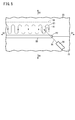
- FIG. 3 is a schematic diagram showing a blowing direction of argon gas, a foreign matter adhering area, and a scanning range of a removal laser beam. It is the schematic which shows the brazing apparatus in the welding start end of a workpiece
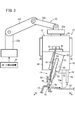
- a brazing device 10 includes a brazing device main body 12, a brazing head 14 and a removal laser head 16, and a vehicle side panel 18 and a roof panel 20 as works are mutually connected. To join.
- the brazing device body 12 is attached to the arm of the robot 22.
- the robot 22 is a multi-axis and multi-joint type robot, and is provided with a first arm 22a to a fourth arm 22d in order from the tip.
- the robot 22 includes a plurality of motors (not shown) that drive the arms 22a to 22d, and these motors are controlled by the robot controller 24.
- the brazing device body 12 is attached to the first arm 22a at the tip. That is, each of the arms 22a to 22d of the robot 22 holds the brazing device body 12 in a cantilever state with the fourth arm 22d as the root portion.
- the root portion is supported on the ground or a pedestal (not shown) fixed to the ground.
- the robot control device 24 can drive each of the arms 22a to 22d by driving the plurality of motors to control the position and posture of the brazing device 10 attached to the first arm 22a.
- the brazing device 10 is moved by the robot 22 in the traveling direction D1 which is the direction in which the joint between the side panel 18 and the roof panel 20 extends.
- the advancing direction D1 of the brazing device 10 is forward, the opposite direction D2 is backward, the left direction D3 is left toward the advancing direction, and the right direction is toward the advancing direction. D4 is called the right side.
- the brazing device 10 is supported by the robot 22 in the postures shown in FIGS. 1 and 2 unless otherwise specified. Be present.
- the brazing device body 12 includes a device attachment portion 26 attached to the first arm 22 a of the robot 22 and device attachment plates 28 attached to the left and right of the device attachment portion 26, respectively.
- the brazing head 14 includes a brazing head body portion 30, a brazing unit 32, a brazing unit rotating portion 34, a wire guide portion 36, and a wire guide moving portion 38.
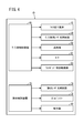
- the brazing head main body 30 includes a box-shaped head main body case 40 attached to the lower front side of the device attachment plate 28 of the brazing apparatus main body 12, and a wire feeding device 42 provided on the upper side of the head main body case 40. Further, the brazing head main body section 30 includes a brazing laser light irradiation section 44 and a brazing control device 46 provided on the upper side of the head main body case 40. The wire feeding device 42 and the brazing laser light irradiation unit 44 are controlled by the brazing control device 46.
- a head body mirror 48 is provided inside the head body case 40.
- the head body mirror 48 reflects the brazing laser light 44 a, which is irradiated downward from the brazing laser light irradiation section 44 and enters the inside of the head body case 40, toward the brazing unit 32 arranged in the front. ..
- the wire feeding device 42 feeds a wire 50 made of a brazing material toward a predetermined position P1 and includes a pair of rollers (not shown) that hold the wire 50, and the wire 50 is rotated by driving the rollers. Send out.
- the brazing laser light 44 a reflected forward by the head body mirror 48 passes through the brazing unit rotating unit 34 and then enters the brazing unit 32.
- the brazing unit 32 includes a box-shaped unit case 52, and a brazing unit mirror 54 that reflects the incident brazing laser beam 44a toward the irradiation position P2 below is disposed inside the unit case 52. Has been done. That is, the brazing unit mirror 54 reflects the brazing laser light 44a downward in the vertical direction.
- a wire guide portion 36 is attached to the front surface of the unit case 52 via a wire guide moving plate 62 described later in detail.
- a blower pipe 56 and a blower 58 (see FIG. 4) for blowing argon gas to the blower pipe 56 are attached to the wire guide portion 36.
- the blower 58 is controlled by the brazing control device 46.
- the brazing laser light irradiation unit for irradiating the brazing laser light 44 a toward the wire 50 includes the brazing laser light irradiation unit 44, the head main body mirror 48, and the brazing unit mirror 54. It is equipped with.
- the wire guide section 36 guides the wire 50 toward the predetermined position P1.
- the wire feeding device 42 and the wire guide portion 36 constitute a wire feeding portion that feeds the wire 50 to a predetermined position.
- the predetermined position P1 which is the guide destination of the wire 50 is the same position as the irradiation position P2 of the brazing laser light 44a which is reflected by the brazing unit mirror 54 and is irradiated downward from the brazing unit 32. Is.
- the blower tube 56 is provided so as to direct air from the irradiation position P2 of the brazing laser light 44a toward the rear in the traveling direction (see FIG. 1). Further, the blower tube 56 is provided so as to direct air from the right side to the left side of the brazing device 10 around the irradiation position P2 of the brazing laser light 44a (see FIG. 2). ..
- the blower unit that blows air toward the irradiation position P2 of the brazing laser light 44a includes a blower pipe 56 and a blower 58.
- the brazing unit rotating unit 34 includes a rotating plate 60 rotatably attached to the front surface of the head body case 40 and a motor 61 (see FIG. 4) for rotating the rotating plate 60.
- the drive of the motor 61 is controlled by the brazing controller 46.
- the rotating plate 60 is formed with a hole (not shown) for passing the brazing laser light 44a reflected forward by the head body mirror 48.
- the wire guide moving unit 38 includes a wire guide moving plate 62 movably attached to the front surface of the unit case 52 of the brazing unit 32 so as to be movable parallel to the irradiation direction of the brazing laser light 44a.
- the wire guide portion 36 is attached to the front surface of the wire guide moving plate 62.
- the wire guide moving unit 38 also includes a wire guide moving mechanism 64 configured by a motor, a gear, and the like for moving the wire guide moving plate 62 (see FIG. 4). It is controlled by the controller 46.
- the wire guide moving mechanism 62 moves the wire guide portion 36 in a direction parallel to the irradiation direction of the brazing laser light 44a by the movement of the wire guide moving plate 62.
- the brazing head 14 is configured to be heavier than the removal laser head 16. Further, since the first arm 22a to the fourth arm 22d of the robot 22 are cantilevered with the fourth arm 22d at the root side, the maximum moment due to the load is applied to the root portion of the fourth arm 22d. It is composed.
- the first arm 22a holds the brazing head 14 on the side closer to the root than the removal laser head 16 (see FIG. 2).
- the moment applied to each of the arms 22a to 22d can be reduced and the durability of each of the arms 22a to 22d can be reduced as compared with the case where the brazing head 14 is held on the side farther from the root than the removal laser head 16. It is possible to improve the property.
- the removal laser head 16 includes a removal laser head body 66 and a removal laser unit 68.
- the removal laser head 16 is arranged to the left of the brazing head 14. That is, the brazing head 14 and the removal laser head 16 are arranged at positions offset from each other in the left-right direction (see FIG. 2).
- the removal laser head main body 66 is attached to the rear side of the device mounting plate 28, and includes a removal control device 70 (see FIG. 4).
- the removal laser unit 68 is attached to the removal laser head main body 66 and includes a removal laser case 72. Inside the removal laser case 72, a removal laser light irradiation section 74 for irradiating the removal laser light 74a toward the front and obliquely downward (D5 direction) is arranged, and the first mirror 76 and the second mirror 76 are provided. A galvanometer mirror 78 as a mirror is arranged. The removal laser light irradiation unit 74 and the galvanometer mirror 78 are controlled by the removal control device 70.
- the first mirror 76 changes the direction of the removed laser light 74a obliquely downward (D5 direction) from the removed laser light irradiation unit 74 by 90° and directs the removed laser light 74a toward the galvano mirror 78 arranged obliquely in front of the first mirror 76. And reflect.
- the galvano mirror 78 reflects the removed laser light 74 a reflected obliquely forward by the first mirror 76 toward the surface of the roof panel 20.
- the galvano mirror 78 has a known structure including a pair of reflection mirrors whose reflection angle can be changed, but is shown in a simplified manner in FIG. 1 and the like.
- the Galvano mirror 78 will be described as having a configuration capable of rotating or swinging about a first shaft 78a oriented in the left-right direction and a second shaft 78b oriented in the front-rear direction.
- the reflection angle of the removed laser beam 74a can be changed.
- the galvanometer mirror 78 is in the rotational position around the first axis 78a shown in FIG. 1, the removed laser light 74a reflected by the first mirror 76 changes its direction by 90° by the galvanometer mirror 78 and forms an angle with the vertical direction D7. It is reflected in the direction D5 forming ⁇ and is irradiated to the irradiation position P3.
- the galvano mirror 78 is provided from the state where the brazing device 10 is at the starting end position of the joining portion to immediately before the ending position of the joining portion, in other words, from the joining start end of the workpiece to immediately before the joining end of the workpiece. Held in a rotating position. Then, when the brazing device 10 reaches the end position of the joint, the galvano mirror 78 is changed to another rotation position. At this other rotational position, the angle formed by the removal laser beam 74a incident on the galvano mirror 78 and the removal laser beam 74a emitted from the galvano mirror 78 is smaller than 90°.
- the angle ⁇ be a value within the range of 30° to 55°. As a result, it is possible to satisfactorily remove the foreign matter particularly at the starting end of the joint. This is because the starting end of the joint between the side panel 18 and the roof panel 20 is bent or curved so as to be bent downward (see FIG. 6).
- the irradiation position P3 of the removal laser light 74a is changed.
- the irradiation position P2 of the contact laser beam 44a can be set at a position close to the rear. Thereby, the foreign matter can be satisfactorily removed not only at the start end of the joint portion but also in a wide range of the joint portion that may have the curved portion.
- the distance between the irradiation position P2 of the brazing laser light 44a and the irradiation position P3 of the removal laser light 74a is preferably, for example, about 5 to 30 mm in order to bring the two as close as possible.
- the irradiation position P2 of the brazing laser light 44a and the irradiation position P3 of the removal laser light 74a should be as close as possible to each other to join the joint from the start end to the end and remove the foreign matter. It is also possible to make the moving distance of the contact device 10 as short as possible.
- the removal laser light irradiation unit for irradiating the surface of the roof panel 20 with the removal laser light 74a for removing the foreign matter adhering to the surface of the roof panel 20 includes the removal laser light irradiation unit 74, the first.
- the mirror 76 and the galvano mirror 78 are provided.
- a suction unit 80 is provided below the removal laser case 72.
- the suction unit 80 sucks the foreign matter removed by the removal laser beam 74a, and the drive of the suction unit 80 is controlled by the removal control device 70.
- the brazing control device 46 drives the motor 61 and the unit of the brazing unit 32 is joined.
- the rotating plate 60 to which the case 52 is attached is rotated.
- the brazing control device 46 detects that the wire 50 has contacted the joint by detecting the increase in the load on the motor 61. Then, the driving of the motor 61 is stopped and the joining is performed at this position.
- the robot control device 24 drives the robot 22 to set the brazing device 10 at the starting end position of the joining portion.
- the brazing device 10 is supported by the first arm 22a of the robot 22 in the posture shown in FIGS. Further, the galvano mirror 78 of the removal laser unit 68 is set at a predetermined rotation position around the first axis 78a and can reflect the laser light incident from the first mirror 76 in the diagonally downward D5 direction. It is like this.
- the robot control device 24 drives the robot 22 to move the brazing device 10 in the traveling direction along a predetermined path for joining the side panel 18 and the roof panel 20.
- the brazing control device 46 drives the wire feeding device 42 to feed the wire 50 in accordance with the movement of the brazing device 10, and also drives the brazing laser light irradiation unit 44 and the blower 58.
- the removal control device 70 drives the removal laser light irradiation unit 74, the galvano mirror 78, and the suction unit 80.
- the galvanometer mirror 78 is periodically swung around the second axis 78b, and the removed laser beam 74a is scanned in the left-right direction.
- the robot controller 24 drives the arms 22a to 22d of the robot 22 so that the lower part of the brazing device 10 is higher than the upper part.
- the brazing device 10 is tilted so as to be located rearward in the traveling direction.
- the removal control device 70 rotates the galvano mirror 78 around the first axis 78a, and the removal laser beam 74a incident on the galvano mirror 78 and the removal laser beam 74a emitted from the galvano mirror 78 form an angle of 90. ° Less than
- the removed laser light 74a reflected by the galvanometer mirror 78 travels obliquely downward (D8 direction) toward the rear in the traveling direction.
- the removal laser beam 74a irradiates the foreign matter in the vicinity of the end of the joining portion, and the foreign matter is satisfactorily removed. This is because the end of the joint between the side panel 18 and the roof panel 20 is bent or curved so as to bend downward.
- the brazing laser light irradiation unit 44 irradiates the brazing laser light 44 a downward toward the head body mirror 48.
- the brazing laser light 44 a emitted from the brazing laser light irradiation section 44 enters the inside of the head body case 40 and is reflected forward by the head body mirror 48 toward the brazing unit mirror 54.
- the brazing laser light 44a reflected forward by the head body mirror 48 enters the inside of the unit case 52 of the brazing unit 32, is reflected vertically downward by the brazing unit mirror 54, and is irradiated to the irradiation position P2. ..
- the irradiation of the brazing laser light 44a melts the wire 50 sent to the predetermined position P1 of the joint.
- the brazing device 10 moves and the portion where the wire 50 is melted is not irradiated with the brazing laser light 44a, the portion where the wire 50 is melted is solidified to form the bead BD, and the side panel 18 and the roof panel. And 20 are joined (see FIG. 5). Note that the wire 50 is not shown in FIG.
- the blower 58 blows argon gas to the blower pipe 56.
- the argon gas that has passed through the blower tube 56 is blown toward the irradiation position P2 of the brazing laser light 44a. Due to this air flow, foreign matter such as soot generated in the step of forming the bead BD is blown in the air flow direction D6 (see FIG. 5).
- the blown foreign matter adheres to the foreign matter adhesion area A1 of the roof panel 20 shown by the chain double-dashed line in FIG.
- the gas blown by the blower 58 is argon gas, but it may be a gas such as another inert gas.
- the removal laser light irradiation unit 74 irradiates the removal laser light 74a toward the first mirror 76 obliquely downward toward the front (D5 direction).
- the removed laser light 74 a emitted from the removed laser light irradiation unit 74 is reflected by the first mirror 76 obliquely forward toward the galvanometer mirror 78.
- the galvanometer mirror 78 reflects the incident removal laser beam 74a obliquely downward (D5 direction) toward the front and scans the removal laser beam 74a in the left-right direction. As the brazing device 10 moves in the traveling direction, the galvanometer mirror 78 also moves in the traveling direction. That is, the galvanometer mirror 78 scans the removal laser beam 74a in the left-right direction while moving in the traveling direction, so that the scanning route R1 of the removal laser beam 74a becomes a scanning route as shown in FIG. Irradiation can be uniform.
- the removal laser beam 74a may be scanned also on the bead BD.
- the oxide film formed on the bead BD may be removed by the removal laser beam 74a.
- the removal laser beam 74a When the removal laser beam 74a is applied to the foreign matter attached to the foreign matter attachment area A1 of the roof panel 20 in the scanning area SA, the foreign matter is blown off or absorbs the energy of the removal laser beam 74a. When the energy of the removal laser beam 74a is absorbed by the foreign matter and changes into thermal energy, the foreign matter is turned into plasma, and therefore the foreign matter can be removed by ablation (melting).
- the suction unit 80 sucks the foreign matter blown off from the roof panel 20 by the removal laser beam 74a. This can prevent the removed foreign matter from adhering to the roof panel 20 again.
- the irradiation direction of the removal laser light 74a with respect to the irradiation direction of the brazing laser light 44a is inclined from the joining start end to immediately before the joining end end by a constant angle ⁇ . Then, the irradiation direction of the removal laser beam 74a may be set to the vertical direction D7 and may be parallel to the irradiation direction of the brazing laser beam 44a.
- foreign matter generated in the process of joining the side panel 18 and the roof panel 20 by the brazing device 10 is removed in the same process by the removal laser head 16 provided in the brazing device 10. Therefore, the number of steps can be reduced and the cost can be reduced as compared with the case where the foreign matter removing step is provided separately from the joining step.
- the joint portion including the joint end portion of the side panel 18 and the roof panel 20 is included. Foreign matter can be satisfactorily removed over a wide range.
- brazing device and the brazing method according to the present invention are not limited to the above-described embodiments, and needless to say, various configurations can be adopted without departing from the scope of the present invention.
Landscapes
- Engineering & Computer Science (AREA)
- Mechanical Engineering (AREA)
- Physics & Mathematics (AREA)
- Optics & Photonics (AREA)
- Laser Beam Processing (AREA)
Abstract
La présente invention concerne un dispositif de brasage (10) comportant : une unité d'émission de faisceau laser de brasage ; et une unité d'émission de faisceau laser d'élimination qui émet, en direction de corps étrangers, un faisceau laser d'élimination (74a) destiné à éliminer les corps étrangers adhérant à la surface d'une pièce (20) lors de l'assemblage de la pièce (20), la direction d'émission du faisceau laser d'élimination (74a) étant inclinée par rapport à la direction d'émission du faisceau laser de brasage (44a), selon un angle prédéterminé dans une direction dans laquelle la position d'émission du faisceau laser d'élimination (74a) s'approche de la position d'émission du faisceau laser de brasage (44a).
Priority Applications (3)
| Application Number | Priority Date | Filing Date | Title |
|---|---|---|---|
| CN201980090018.6A CN113382817A (zh) | 2019-01-25 | 2019-09-27 | 钎焊装置和钎焊方法 |
| US17/424,902 US20220118539A1 (en) | 2019-01-25 | 2019-09-27 | Brazing device and brazing method |
| JP2020567364A JPWO2020152913A1 (ja) | 2019-01-25 | 2019-09-27 | ろう接装置およびろう接方法 |
Applications Claiming Priority (2)
| Application Number | Priority Date | Filing Date | Title |
|---|---|---|---|
| JP2019010930 | 2019-01-25 | ||
| JP2019-010930 | 2019-01-25 |
Publications (1)
| Publication Number | Publication Date |
|---|---|
| WO2020152913A1 true WO2020152913A1 (fr) | 2020-07-30 |
Family
ID=71736210
Family Applications (1)
| Application Number | Title | Priority Date | Filing Date |
|---|---|---|---|
| PCT/JP2019/038206 Ceased WO2020152913A1 (fr) | 2019-01-25 | 2019-09-27 | Dispositif de brasage et procédé de brasage |
Country Status (4)
| Country | Link |
|---|---|
| US (1) | US20220118539A1 (fr) |
| JP (1) | JPWO2020152913A1 (fr) |
| CN (1) | CN113382817A (fr) |
| WO (1) | WO2020152913A1 (fr) |
Families Citing this family (1)
| Publication number | Priority date | Publication date | Assignee | Title |
|---|---|---|---|---|
| US11852076B2 (en) * | 2022-01-21 | 2023-12-26 | Collins Engine Nozzles, Inc. | Brazing using localized heating |
Citations (5)
| Publication number | Priority date | Publication date | Assignee | Title |
|---|---|---|---|---|
| JP2005279686A (ja) * | 2004-03-29 | 2005-10-13 | Toshiba Corp | レーザろう付装置および方法 |
| JP2007152381A (ja) * | 2005-12-02 | 2007-06-21 | Daihatsu Motor Co Ltd | レーザブレージング加工方法およびレーザブレージング加工装置 |
| JP2013176785A (ja) * | 2012-02-28 | 2013-09-09 | Honda Motor Co Ltd | 金属接合部材の製造方法及び金属接合部材 |
| WO2016052602A1 (fr) * | 2014-10-03 | 2016-04-07 | 本田技研工業株式会社 | Structure de toit de véhicule et procédé de fabrication de structure de toit de véhicule |
| WO2019138574A1 (fr) * | 2018-01-15 | 2019-07-18 | 本田技研工業株式会社 | Dispositif de brasage et procédé de brasage |
Family Cites Families (16)
| Publication number | Priority date | Publication date | Assignee | Title |
|---|---|---|---|---|
| CN1008246B (zh) * | 1985-05-17 | 1990-06-06 | 罗伯特·兰根 | 清除金属表面污物,特别是锈蚀的方法 |
| JP2000197983A (ja) * | 1998-12-28 | 2000-07-18 | Toshiba Corp | レ―ザ切断方法およびレ―ザ切断装置 |
| US7405114B2 (en) * | 2002-10-16 | 2008-07-29 | Semiconductor Energy Laboratory Co., Ltd. | Laser irradiation apparatus and method of manufacturing semiconductor device |
| JP2007075872A (ja) * | 2005-09-16 | 2007-03-29 | Nissan Motor Co Ltd | レーザブレージング接合工法 |
| EP1920864B1 (fr) * | 2006-11-13 | 2022-07-13 | Volvo Car Corporation | Méthode de brasage par laser à deux points |
| CN101143364A (zh) * | 2007-10-08 | 2008-03-19 | 南开大学 | 超声检测窄脉宽激光除污机及其除污方法 |
| JP5446334B2 (ja) * | 2009-03-09 | 2014-03-19 | 日産自動車株式会社 | レーザ溶接装置、およびレーザ溶接方法 |
| JP5419807B2 (ja) * | 2010-06-16 | 2014-02-19 | 日立Geニュークリア・エナジー株式会社 | レーザ溶接装置 |
| DE102014203025A1 (de) * | 2014-02-19 | 2015-08-20 | Bayerische Motoren Werke Aktiengesellschaft | Verfahren zum Laserstrahlschweißen und Schweißkopf |
| CN105458445B (zh) * | 2014-09-11 | 2018-09-18 | 大族激光科技产业集团股份有限公司 | 一种激光锡焊装置及焊接方法 |
| ES2887211T3 (es) * | 2015-06-19 | 2021-12-22 | Ipg Photonics Corp | Sistema de soldadura láser con un cabezal de soldadura láser dotado de espejos móviles duales que proporcionan movimiento de haz con campo de visión limitado |
| KR101713728B1 (ko) * | 2015-07-31 | 2017-03-09 | 현대자동차 주식회사 | 루프 레이저 브레이징 시스템용 브레이징 어셈블리 |
| US20190061053A1 (en) * | 2017-08-24 | 2019-02-28 | GM Global Technology Operations LLC | Laser brazing of metal workpieces with relative movement between laser beam and filler wire |
| CN107378165A (zh) * | 2017-09-13 | 2017-11-24 | 安徽江淮汽车集团股份有限公司 | 一种激光焊接方法 |
| US10724997B2 (en) * | 2018-04-30 | 2020-07-28 | The Boeing Company | System combining laser ablation with ultrasound inspection of parts |
| CN109014943B (zh) * | 2018-07-19 | 2019-10-08 | 华中科技大学 | 一种用于黑卷无头轧制中的清洗焊接一体化装置 |
-
2019
- 2019-09-27 US US17/424,902 patent/US20220118539A1/en not_active Abandoned
- 2019-09-27 WO PCT/JP2019/038206 patent/WO2020152913A1/fr not_active Ceased
- 2019-09-27 CN CN201980090018.6A patent/CN113382817A/zh active Pending
- 2019-09-27 JP JP2020567364A patent/JPWO2020152913A1/ja not_active Ceased
Patent Citations (5)
| Publication number | Priority date | Publication date | Assignee | Title |
|---|---|---|---|---|
| JP2005279686A (ja) * | 2004-03-29 | 2005-10-13 | Toshiba Corp | レーザろう付装置および方法 |
| JP2007152381A (ja) * | 2005-12-02 | 2007-06-21 | Daihatsu Motor Co Ltd | レーザブレージング加工方法およびレーザブレージング加工装置 |
| JP2013176785A (ja) * | 2012-02-28 | 2013-09-09 | Honda Motor Co Ltd | 金属接合部材の製造方法及び金属接合部材 |
| WO2016052602A1 (fr) * | 2014-10-03 | 2016-04-07 | 本田技研工業株式会社 | Structure de toit de véhicule et procédé de fabrication de structure de toit de véhicule |
| WO2019138574A1 (fr) * | 2018-01-15 | 2019-07-18 | 本田技研工業株式会社 | Dispositif de brasage et procédé de brasage |
Also Published As
| Publication number | Publication date |
|---|---|
| US20220118539A1 (en) | 2022-04-21 |
| JPWO2020152913A1 (ja) | 2021-10-28 |
| CN113382817A (zh) | 2021-09-10 |
Similar Documents
| Publication | Publication Date | Title |
|---|---|---|
| JP5864557B2 (ja) | 金属薄板部分をレーザ接合する方法および装置 | |
| CN109202287B (zh) | 激光焊接方法及激光焊接装置 | |
| JP3380416B2 (ja) | レーザ溶接装置 | |
| US9168610B2 (en) | Laser apparatus for welding | |
| CN101687282A (zh) | 焊接装置及焊接方法 | |
| JP5595139B2 (ja) | 溶接方法及び溶接システム | |
| JP4100593B2 (ja) | レーザ溶接装置 | |
| CN110653491A (zh) | 激光加工设备及方法 | |
| EP3412401B1 (fr) | Dispositif de soudage au laser | |
| JP5446334B2 (ja) | レーザ溶接装置、およびレーザ溶接方法 | |
| WO2020152913A1 (fr) | Dispositif de brasage et procédé de brasage | |
| CN111565876B (zh) | 硬钎焊装置以及方法 | |
| JP2022037665A (ja) | 溶接方法及び溶接装置 | |
| JP4688634B2 (ja) | レーザ溶接方法とレーザ溶接装置 | |
| JP6951040B2 (ja) | レーザ加工装置及びレーザ加工方法 | |
| JPH10180471A (ja) | レーザ溶接装置 | |
| JP2006334628A (ja) | 溶接装置 | |
| JP2019093423A (ja) | ワーク加工装置 | |
| JP2003225784A (ja) | レーザブレージング加工方法および加工装置 | |
| KR100781886B1 (ko) | 파이프 궤도용접용 하이브리드 레이저 용접 시스템 | |
| JP4036388B2 (ja) | レーザ溶接装置 | |
| JPH10180472A (ja) | レーザ溶接装置 | |
| JP2000005888A (ja) | レーザ突合せ溶接方法 | |
| CN218223618U (zh) | 刷式清洁装置 | |
| JP2003191085A (ja) | Yagレーザー溶接方法 |
Legal Events
| Date | Code | Title | Description |
|---|---|---|---|
| 121 | Ep: the epo has been informed by wipo that ep was designated in this application |
Ref document number: 19911074 Country of ref document: EP Kind code of ref document: A1 |
|
| ENP | Entry into the national phase |
Ref document number: 2020567364 Country of ref document: JP Kind code of ref document: A |
|
| NENP | Non-entry into the national phase |
Ref country code: DE |
|
| 122 | Ep: pct application non-entry in european phase |
Ref document number: 19911074 Country of ref document: EP Kind code of ref document: A1 |