WO2020153389A1 - Dispositif à aimant permanent et dispositif de génération de champ magnétique - Google Patents
Dispositif à aimant permanent et dispositif de génération de champ magnétique Download PDFInfo
- Publication number
- WO2020153389A1 WO2020153389A1 PCT/JP2020/002054 JP2020002054W WO2020153389A1 WO 2020153389 A1 WO2020153389 A1 WO 2020153389A1 JP 2020002054 W JP2020002054 W JP 2020002054W WO 2020153389 A1 WO2020153389 A1 WO 2020153389A1
- Authority
- WO
- WIPO (PCT)
- Prior art keywords
- permanent magnet
- magnetic field
- magnet
- pieces
- piece
- Prior art date
- Legal status (The legal status is an assumption and is not a legal conclusion. Google has not performed a legal analysis and makes no representation as to the accuracy of the status listed.)
- Ceased
Links
Images










Classifications
-
- H—ELECTRICITY
- H01—ELECTRIC ELEMENTS
- H01F—MAGNETS; INDUCTANCES; TRANSFORMERS; SELECTION OF MATERIALS FOR THEIR MAGNETIC PROPERTIES
- H01F7/00—Magnets
- H01F7/02—Permanent magnets [PM]
-
- H—ELECTRICITY
- H05—ELECTRIC TECHNIQUES NOT OTHERWISE PROVIDED FOR
- H05H—PLASMA TECHNIQUE; PRODUCTION OF ACCELERATED ELECTRICALLY-CHARGED PARTICLES OR OF NEUTRONS; PRODUCTION OR ACCELERATION OF NEUTRAL MOLECULAR OR ATOMIC BEAMS
- H05H7/00—Details of devices of the types covered by groups H05H9/00, H05H11/00, H05H13/00
- H05H7/04—Magnet systems, e.g. undulators, wigglers; Energisation thereof
Definitions
- Equation 1 The normal component of the nth-order multipole expansion magnetic field at the magnetic field evaluation position (r, ⁇ ) is expressed by Equation 1, and the skew component is expressed by Equation 2.
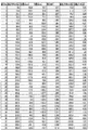
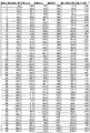
- FIG. 12 is a table in which the rotation angle is calculated in consideration of the variation of the permanent magnet pieces in the first row of the permanent magnet two-row configuration
- FIG. 13 is the table of FIG. 13 showing the variation of the permanent magnet pieces in the second row of the permanent magnet two-row configuration. It is the table which calculated the rotation angle which considered.
- the permanent magnet 2 a samarium-cobalt magnet is used, and the intensity of its magnetization (residual magnetization) is randomly set from 1.0 [T] to 1.1 [T] from the catalog value.
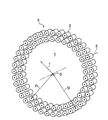
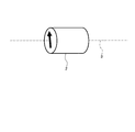
- the calculation was performed using the permanent magnet piece 2 having a diameter of 18 mm, but the permanent magnet piece 2 is generally 5 mm to 30 mm in diameter and 10 mm to 50 mm in length.
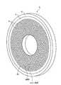
- the diameter of the permanent magnet piece 2 may be appropriately selected depending on the size of the magnetic field evaluation space 1 and the size of the magnet module 6. In particular, since the number of the permanent magnet pieces 2 in the circumferential direction corresponds to the periodic magnetic field distribution, the diameter of the permanent magnet pieces 2 should be selected so that the number of angle divisions exceeds 32.
- the magnetic field generation device 20 needs to be assembled after each of the magnet modules 6 has a magnetic field formed with high accuracy.
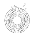
- the magnet modules 11 and 12 are configured such that the direction of magnetization is 3 ⁇ with respect to the phase angle ⁇ , as in the above embodiment. Further, the magnet module 11 (FIG. 19) is rotated right by the rotation angle ⁇ , and the magnet module 12 (FIG. 18) is rotated left by the rotation angle ⁇ .
- the four guide rollers 21 rotatably hold the laminated magnet modules 6 while preventing positional deviation.
- the plurality of links 22 (22a, 22b) are provided for each magnet module 6. One end of the link 22 is attached to the peripheral surface of the magnet module 6, and the nut 27 is rotatably attached to the other end.
- the link 22a is attached to the magnet module 6a, and the link 22b is attached to the magnet module 6b adjacent to the magnet module 6a.
- the magnet rotation lever 24 moves all the rotation fine adjustment shafts 23 up and down. As a result, the links 22a and 22b move up and down, so that the magnet modules 6a and 6b are rotated in opposite directions from the initial reference position. As a result, the magnet rotation lever 24 can make the normal component have a desired strength.
- the fixing screws 25 and 26 fix the positions of the magnet modules 6a and 6b after the magnetic field is adjusted.
Landscapes
- Physics & Mathematics (AREA)
- Engineering & Computer Science (AREA)
- Electromagnetism (AREA)
- Power Engineering (AREA)
- Optics & Photonics (AREA)
- Plasma & Fusion (AREA)
- Spectroscopy & Molecular Physics (AREA)
- Particle Accelerators (AREA)
- Magnetic Resonance Imaging Apparatus (AREA)
Abstract
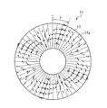
Un dispositif à aimant permanent (6) est caractérisé en ce qu'une pluralité de pièces d'aimant permanent (2) ayant la même forme sont agencées de façon à entourer un espace d'évaluation de champ magnétique en colonne (1). La direction de magnétisation des pièces d'aimant permanent (2) a un composant circonférentiel d'un réseau annulaire des pièces d'aimant permanent (2). La direction de magnétisation des pièces d'aimant permanent (2) est une direction obtenue par correction de l'angle de (n+2) fois un angle phi formé par une ligne de référence (axe x) reliant une pièce d'aimant permanent (2) en tant que référence et l'axe central O de la colonne, et un segment de ligne reliant une autre pièce d'aimant permanent et l'axe central de colonne, un angle de correction étant réglé à un angle pour corriger une distribution de champ magnétique due à des variations de magnétisation de la pluralité de pièces d'aimant permanent.
Priority Applications (1)
| Application Number | Priority Date | Filing Date | Title |
|---|---|---|---|
| JP2020568179A JP7170068B2 (ja) | 2019-01-23 | 2020-01-22 | 永久磁石装置、及び磁場発生装置 |
Applications Claiming Priority (2)
| Application Number | Priority Date | Filing Date | Title |
|---|---|---|---|
| JP2019-009694 | 2019-01-23 | ||
| JP2019009694 | 2019-01-23 |
Publications (1)
| Publication Number | Publication Date |
|---|---|
| WO2020153389A1 true WO2020153389A1 (fr) | 2020-07-30 |
Family
ID=71736425
Family Applications (1)
| Application Number | Title | Priority Date | Filing Date |
|---|---|---|---|
| PCT/JP2020/002054 Ceased WO2020153389A1 (fr) | 2019-01-23 | 2020-01-22 | Dispositif à aimant permanent et dispositif de génération de champ magnétique |
Country Status (2)
| Country | Link |
|---|---|
| JP (1) | JP7170068B2 (fr) |
| WO (1) | WO2020153389A1 (fr) |
Cited By (3)
| Publication number | Priority date | Publication date | Assignee | Title |
|---|---|---|---|---|
| CN114055258A (zh) * | 2021-11-19 | 2022-02-18 | 浙江师范大学 | 一种磁性抛光装置及磁性抛光控制方法 |
| CN115824328A (zh) * | 2022-12-19 | 2023-03-21 | 中国原子能科学研究院 | 永磁式液态金属流量计 |
| JP2023152328A (ja) * | 2022-04-04 | 2023-10-17 | 横河電機株式会社 | 磁石保持装置、磁化装置および着磁方法 |
Citations (3)
| Publication number | Priority date | Publication date | Assignee | Title |
|---|---|---|---|---|
| JPH06224027A (ja) * | 1993-01-22 | 1994-08-12 | Shin Etsu Chem Co Ltd | 磁場発生装置 |
| JP2003142300A (ja) * | 2001-11-05 | 2003-05-16 | Hitachi Metals Ltd | 周期磁場発生装置 |
| JP2014054633A (ja) * | 2005-06-24 | 2014-03-27 | Sepmag Systems Sl | 磁性粒子を分離するためのデバイス及び方法 |
-
2020
- 2020-01-22 JP JP2020568179A patent/JP7170068B2/ja active Active
- 2020-01-22 WO PCT/JP2020/002054 patent/WO2020153389A1/fr not_active Ceased
Patent Citations (3)
| Publication number | Priority date | Publication date | Assignee | Title |
|---|---|---|---|---|
| JPH06224027A (ja) * | 1993-01-22 | 1994-08-12 | Shin Etsu Chem Co Ltd | 磁場発生装置 |
| JP2003142300A (ja) * | 2001-11-05 | 2003-05-16 | Hitachi Metals Ltd | 周期磁場発生装置 |
| JP2014054633A (ja) * | 2005-06-24 | 2014-03-27 | Sepmag Systems Sl | 磁性粒子を分離するためのデバイス及び方法 |
Cited By (5)
| Publication number | Priority date | Publication date | Assignee | Title |
|---|---|---|---|---|
| CN114055258A (zh) * | 2021-11-19 | 2022-02-18 | 浙江师范大学 | 一种磁性抛光装置及磁性抛光控制方法 |
| CN114055258B (zh) * | 2021-11-19 | 2023-04-18 | 浙江师范大学 | 一种磁性抛光装置及磁性抛光控制方法 |
| JP2023152328A (ja) * | 2022-04-04 | 2023-10-17 | 横河電機株式会社 | 磁石保持装置、磁化装置および着磁方法 |
| JP7567851B2 (ja) | 2022-04-04 | 2024-10-16 | 横河電機株式会社 | 磁石保持装置、磁化装置および着磁方法 |
| CN115824328A (zh) * | 2022-12-19 | 2023-03-21 | 中国原子能科学研究院 | 永磁式液态金属流量计 |
Also Published As
| Publication number | Publication date |
|---|---|
| JP7170068B2 (ja) | 2022-11-11 |
| JPWO2020153389A1 (ja) | 2021-10-21 |
Similar Documents
| Publication | Publication Date | Title |
|---|---|---|
| JP4145248B2 (ja) | 永久磁石式磁界発生装置 | |
| US8390201B2 (en) | Multi-column electron beam exposure apparatus and magnetic field generation device | |
| WO2020153389A1 (fr) | Dispositif à aimant permanent et dispositif de génération de champ magnétique | |
| TWI704846B (zh) | 波盪器 | |
| KR102410836B1 (ko) | 다이폴 링 자계 발생 장치 | |
| EP3887839A1 (fr) | Réseaux d'aimants asymétriques légers avec anneaux magnétiques à phase mixte | |
| JP2017009389A (ja) | 粒子線ビームの制御電磁石及びこれを備えた照射治療装置 | |
| CN115426762A (zh) | 基于电机控制调节的永磁四极磁铁 | |
| JP4558563B2 (ja) | 永久磁石式磁界発生装置 | |
| Koratzinos et al. | A method for greatly reduced edge effects and crosstalk in CCT magnets | |
| Li et al. | Tuning method for phase shifters with very low first field integral errors for the European X-ray Free Electron Laser | |
| JP7589094B2 (ja) | 粒子線治療装置、および、粒子線治療装置の制御方法 | |
| JP6588849B2 (ja) | ビーム輸送用超電導磁石装置、ビーム輸送システム、粒子線治療システム、ビーム輸送用超伝導磁石配置方法 | |
| Sugimoto et al. | Design study of the SuperKEKB interaction region optics | |
| Schmerge | LCLS gun solenoid design considerations | |
| Saito et al. | Proposal of a vertically polarized superconducting multipole wiggler using Nb3Sn coils | |
| Li et al. | Printed-circuit magnets for the university of maryland electron ring (umer)-new developments | |
| Chung et al. | Reduction of dynamic multipole content in insertion devices using flat wires | |
| Kalimov et al. | Optimization of the sextupole magnets with trim coils for the collector ring of the fair project | |
| Danby et al. | Magnet design for a very high energy synchrotron employing a separated function magnet lattice | |
| JPS63224230A (ja) | X線露光装置 | |
| Kim et al. | Performance of quadrupole and sextupole magnets for the advanced photon source storage ring | |
| KR0147040B1 (ko) | 방사광 가속기용 6극전자석 | |
| Dong et al. | Development of a novel tunable gradient permanent quadrupole magnet | |
| Masson et al. | Effect of an iron yoke of the field homogeneity in a superconducting double-helix bent dipole |
Legal Events
| Date | Code | Title | Description |
|---|---|---|---|
| 121 | Ep: the epo has been informed by wipo that ep was designated in this application |
Ref document number: 20745641 Country of ref document: EP Kind code of ref document: A1 |
|
| ENP | Entry into the national phase |
Ref document number: 2020568179 Country of ref document: JP Kind code of ref document: A |
|
| NENP | Non-entry into the national phase |
Ref country code: DE |
|
| 122 | Ep: pct application non-entry in european phase |
Ref document number: 20745641 Country of ref document: EP Kind code of ref document: A1 |