WO2020153550A1 - Procédé de réglage de temporisateur et temporisateur utilisant ledit procédé - Google Patents
Procédé de réglage de temporisateur et temporisateur utilisant ledit procédé Download PDFInfo
- Publication number
- WO2020153550A1 WO2020153550A1 PCT/KR2019/007839 KR2019007839W WO2020153550A1 WO 2020153550 A1 WO2020153550 A1 WO 2020153550A1 KR 2019007839 W KR2019007839 W KR 2019007839W WO 2020153550 A1 WO2020153550 A1 WO 2020153550A1
- Authority
- WO
- WIPO (PCT)
- Prior art keywords
- time
- timer
- time display
- display structure
- deadline
- Prior art date
- Legal status (The legal status is an assumption and is not a legal conclusion. Google has not performed a legal analysis and makes no representation as to the accuracy of the status listed.)
- Ceased
Links
Images





Classifications
-
- G—PHYSICS
- G04—HOROLOGY
- G04F—TIME-INTERVAL MEASURING
- G04F1/00—Apparatus which can be set and started to measure-off predetermined or adjustably-fixed time intervals without driving mechanisms, e.g. egg timers
- G04F1/005—Apparatus which can be set and started to measure-off predetermined or adjustably-fixed time intervals without driving mechanisms, e.g. egg timers using electronic timing, e.g. counting means
-
- G—PHYSICS
- G04—HOROLOGY
- G04F—TIME-INTERVAL MEASURING
- G04F3/00—Apparatus which can be set and started to measure-off predetermined or adjustably-fixed time intervals with driving mechanisms, e.g. dosimeters with clockwork
- G04F3/06—Apparatus which can be set and started to measure-off predetermined or adjustably-fixed time intervals with driving mechanisms, e.g. dosimeters with clockwork with electric driving mechanisms
- G04F3/08—Additional arrangements in connection with ordinary electric clocks for this purpose
-
- G—PHYSICS
- G04—HOROLOGY
- G04B—MECHANICALLY-DRIVEN CLOCKS OR WATCHES; MECHANICAL PARTS OF CLOCKS OR WATCHES IN GENERAL; TIME PIECES USING THE POSITION OF THE SUN, MOON OR STARS
- G04B19/00—Indicating the time by visual means
- G04B19/20—Indicating by numbered bands, drums, discs, or sheets
- G04B19/202—Indicating by numbered bands, drums, discs, or sheets by means of turning discs
-
- G—PHYSICS
- G04—HOROLOGY
- G04F—TIME-INTERVAL MEASURING
- G04F7/00—Apparatus for measuring unknown time intervals by non-electric means
- G04F7/04—Apparatus for measuring unknown time intervals by non-electric means using a mechanical oscillator
- G04F7/08—Watches or clocks with stop devices, e.g. chronograph
- G04F7/0866—Special arrangements
- G04F7/089—Special arrangements indicating measured time by other than hands, e.g. numbered bands, drums, discs or sheet
-
- G—PHYSICS
- G04—HOROLOGY
- G04G—ELECTRONIC TIME-PIECES
- G04G9/00—Visual time or date indication means
- G04G9/0023—Visual time or date indication means by light valves in general
- G04G9/0029—Details
- G04G9/0035—Details constructional
- G04G9/0041—Illumination devices
Definitions
- the present invention relates to a timer setting method and a timer using the method. More specifically, it relates to a method and apparatus for visually expressing a lapse of a set time on a timer to increase a time recognition effect through a user's timer.
- Time management can be defined in different ways depending on the situation: doing the right thing at the right time, distributing the right time between work and leisure, performing planned procedures to achieve desirable goals, and using time efficiently , And even managing and controlling the overall aspect of life.
- time management can increase self-efficacy, which can affect future work.
- the present invention aims to solve all the above-mentioned problems.
- an object of the present invention is to set a required time based on the short-range communication technology and visually provide the set time to a user.
- an object of the present invention is to help users manage their time and achieve their goals by managing immersion time based on a timer.
- the present invention aims to perform management of a plurality of divided times based on the time display area of one timer.
- a representative configuration of the present invention for achieving the above object is as follows.
- a timer setting method may include the step of receiving a target time by a timer and the timer counting the target time by changing an area of a time display area based on the target time.
- the width of the time display area may be changed based on rotation of a plurality of time display structures.
- the timer may include a communication unit implemented to receive the target time and a timer driving unit implemented to count the target time by changing the width of the time display area based on the target time.
- the width of the time display area may be changed based on rotation of a plurality of time display structures.
- a necessary time is set based on the short-range communication technology and information on the set time can be visually provided to the user.
- management of a plurality of divided times may be performed based on the time display area of one timer.
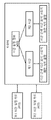
- FIG. 1 is a conceptual diagram showing a timer according to an embodiment of the present invention.
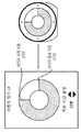
- FIG. 2 is a conceptual diagram showing the operation of a timer display according to an embodiment of the present invention.
- FIG. 3 is a conceptual diagram showing the operation of a timer display according to an embodiment of the present invention.
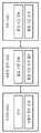
- FIG. 4 is a conceptual diagram showing a timer setting method according to an embodiment of the present invention.
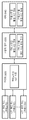
- FIG. 5 is a conceptual diagram illustrating a method of measuring immersion time based on a timer according to an embodiment of the present invention.
- FIG. 6 is a conceptual diagram illustrating a method of measuring immersion time by category according to an embodiment of the present invention.
- FIG. 7 is a conceptual diagram showing a timer display setting method according to an embodiment of the present invention.
- FIG. 8 is a conceptual diagram illustrating a method of correcting immersion time based on a timer according to an embodiment of the present invention.
- FIG. 9 is a conceptual diagram showing an alarm method for a deadline on a timer according to an embodiment of the present invention.
- FIG. 10 is a conceptual diagram illustrating a method for determining a priority of a deadline according to an embodiment of the present invention.
- FIG. 11 is a conceptual diagram illustrating a method for determining a priority of a deadline according to an embodiment of the present invention.
- FIG. 1 is a conceptual diagram showing a timer according to an embodiment of the present invention.
- the timer may include a timer display 100, a timer driver 110, a communication unit 120, a battery unit 130, a switch unit 140, an alarm unit 150, and a control unit 160.
- a timer display 100 a timer display 100, a timer driver 110, a communication unit 120, a battery unit 130, a switch unit 140, an alarm unit 150, and a control unit 160.
- the timer driving unit 110 may be implemented as a motor for driving the timer.
- the timer driver 110 may drive the timer display 100 to change the time display on the timer display 100 based on the set time.
- the timer driver 110 may drive the timer display 100 according to a target time based on a time setting card for time setting. For example, when the time set based on the time setting card is the first time, the first time in the timer display 100 at a time change interval (for example, 1 minute, 1 second, etc.) based on the first time.
- a time change interval for example, 1 minute, 1 second, etc.
- the change from the start time to the end time of the first time set by changing the movement of the display structure and/or the second time display structure may be visually expressed according to the change in time.
- the rotation speed of the first time display structure and/or the second time display structure in the timer display 100 may be changed according to the target time set by the time setting card.
- the timer driving unit 110 changes the movement of the first time display structure and/or the second time display structure on the timer display 100 at different time change intervals according to the time setting card to visualize the time display area according to the target time. Can induce change.
- the timer display 100 may be implemented to visually represent a change in target time.
- the timer display 100 may be implemented such that the time display area is visually changed according to a time change from a start time to an end time according to a target time based on the first time display structure and the second time display structure.
- the time display area may be filled with a specific color as the first color changes to the second color according to the change of time. For example, when the first time is 30 minutes, the time display area of the timer display may be the first color at the set start time of 30 minutes, and the first color changes to the second color as it moves from the start time to the end time.
- the progress of the target time can be displayed.
- the first color may be 100% of the timer display 100 and the second color may be 0% of the timer display 100, and the first color from the start time to the end time is the timer display 100 ) Is changed from 100% to 0%, the second color is changed from 0% to 100% of the timer display 100, and at the end time, the first color is 0% and the second color of the timer display 100. It may be 100% of the timer display 100.
- the communication unit 120 may be implemented to enable communication with a time setting card.
- the time setting information may be received from the time setting card by communicating with the communication unit 120 of the time setting card using short-range communication (eg, near field communication (NFC)).
- NFC near field communication
- the time setting information received by the communication unit 120 may be transmitted to the timer driver 110 to determine a target time.
- the battery unit 130 may be implemented to supply power to at least one component of the timer so that each component is operable.
- the switch unit 140 may be implemented to transmit a counting start signal for a set time. After setting the target time on the timer, the switch of the switch unit 140 may be pressed to start counting of the target time.
- the alarm unit 150 may be implemented to provide an alarm signal related to a target time.
- the alarm unit 150 may be implemented to notify the start of counting of the target time and the end of counting of the target time.
- the control unit 160 may be implemented to control operations of the timer driving unit 110, the timer display 100, the communication unit 120, the battery unit 130, the switch unit 140, and the alarm unit 150.
- the timer driving unit 110 displays a change in time by changing a time display structure on the timer display 100 using a physical force such as a motor.
- the timer display 100 may also be implemented as an electronic display such as a light emitting diode (LED) rather than a mechanical structure, and such an embodiment may also be included in the scope of the present invention.
- LED light emitting diode
- FIG. 2 is a conceptual diagram showing the operation of a timer display according to an embodiment of the present invention.
- a time display area may be changed according to counting of a target time on a timer display.
- the time display area in the shape of a concentric circle at the start time of the target time may be set as the first color 210.
- the elapse of the target time may be visually provided as the first color 210 changes to the second color 220 according to a change in time from the start time to the end time of the target time. Specifically, as the first color 210 changes to the second color 220 based on a specific point of the concentric circle, a change in target time may be visually expressed.
- the rate of change from the first color 210 to the second color 220 may be determined according to a time change interval according to a target time. For example, when the target time is the first time (for example, 30 minutes), the time change interval is set to the first interval, and the rate of change from the first color 210 to the second color 220 is reduced. Determined by 1 rate of change, and when the set time is the second time (for example, 1 hour), the time change interval is set to the second interval to change the color from the first color 210 to the second color 220 The speed can be determined as the second rate of change.
- the first change rate and the second change rate may be determined based on changes in the first time display structure and the second time display structure.
- all of the first color 210 may be changed to the second color 220 at the end time of the target time.
- FIG. 3 is a conceptual diagram showing the operation of a timer display according to an embodiment of the present invention.
- a method for indicating a change in a target time based on the movement of the first time display structure and/or the second time display structure on the timer display is disclosed.
- the timer driving unit performs movement (or rotational speed) of the first time display structure 310 and/or the second time display structure 320 on the timer display at different time change intervals according to the time setting card. Can be changed.
- the first time display structure 310 and the second time display structure 320 are implemented in a circular shape, and the first time display structure 310 has a first connection point 315 and the second time display structure 320 is It may have a second connection point (325).
- the second time display structure 320 is located on the top of the first time display structure 310, and the first connection point 315 of the first time display structure 310 and the second of the second time display structure 320 The connection point 325 may meet.
- the first time display structure 310 based on the first connection point 315 and the second connection point 325 according to the rotation angle according to the rotation of the first time display structure 310 and the second time display structure 320 ) May be rotated as the first surface of) is positioned on the top of the second surface of the second time display structure.
- the first surface of the first time display structure 310 is the second time display structure while only the second surface is visible according to the rotation of the first time display structure 310 and/or the second time display structure 320
- the first surface may gradually appear while covering the second surface of 320.
- the first time display structure 310 and/or the second time display structure 320 are rotated in consideration of the time change interval according to the change of the target time, and the screen on the timer is the first side from the second side. As it changes to, the progress of the target time can be displayed.
- the second time display structure 320 may be located on the top surface of the first time display structure 310. At this time, the second surface of the second time display structure 320 may be displayed on the timer display.
- the first time according to the rotation of the first time display structure 310 and/or the second time display structure 320 based on the first connection structure 315 and the second connection structure 315
- the first side of the first time display structure 310 moves to the top of the second side of the second time display structure 320 while the first side of the display structure 310 moves to the top of the second side of the second time display structure 320. 2 sides can be covered.
- the second surface on the timer display gradually changes to the first surface so that the elapse of the target time can be displayed.
- the first surface of the first time display structure 310 may be displayed on the timer display.
- the second time display structure 320 may be placed on the upper surface of the first time display structure 310 again.
- the timer display can be displayed as a number, but can be expressed as n-segment to perform a timer function by adjusting the movement angle per hour for any time setting.
- an additional third time display structure may be used and utilized for additional time display.
- the third time display structure includes a third connection structure, and the third time display structure is located on the upper surface of the second time display structure 320 to display additional time ideas in a separate color through the third time display structure. Is possible.
- a position adjustment structure for adjusting the position of the time display structure in order to set the position of the time display structure using a connection structure on the time display structure may be implemented on the timer. For example, when the start switch is pressed, the first time display structure 310 and/or the second time display structure 320 are rotated based on the first connection structure 315 and the second connection structure 315. The first side of the first time display structure 310 is moved to the top of the second side of the second time display structure 320 while the first side of the first time display structure 310 is the second time display structure 320 Must cover the second side of.
- the position adjustment structure can be used to facilitate such operation by the angle and position of the position second time display structure 320 and/or the second connection structure, the angle of the first time display structure 310 and/or the first connection structure, and By adjusting the position, the first side of the first time display structure 310 is rotated according to the rotation of the first time display structure 310 and/or the second time display structure 320. It can be moved to the top of the two sides.
- FIG. 4 is a conceptual diagram showing a timer setting method according to an embodiment of the present invention.
- the time setting card may be a card for setting the time to be set in the timer.
- the target time of the first time setting card 410 is 30 minutes, and when the first time setting card 410 is inserted into the timer, the timer may be set to 30 minutes.
- the target time of the second time setting card 420 is 1 hour, and the second time setting card 420 is inserted into the timer, the timer may be set to 1 hour.
- the communication unit communicates with the communication unit of the time setting card using short-range communication (eg, near field communication (NFC)) to receive time setting information 450 from the time setting card. I can receive it.
- the time setting information 450 received by the communication unit may be transmitted to a timer driving unit to determine a target time.
- the timer driver determines a time change interval (or rotational speed of the time display structure) according to the first time, and displays the first time display structure and/or the second time on the timer display You can change the movement of the structure.
- the timer driver determines a time change interval (or rotational speed of the time display structure) according to the second time, and the first time display structure and/or the second on the timer display. You can change the movement of the time display structure.
- a method of determining a target time of a timer according to the time setting card by mechanically inserting a time setting card has been disclosed, but it is also possible to determine a target time of the timer through a timer application of a user device based on the communication unit. For example, a target time desired to be set through a timer may be determined through a timer application of a user device. When the timer target time is determined to be 30 minutes through the user interface on the timer application, the timer target time information is transmitted to the timer, and the time change interval (or rotational speed of the time display structure) of the timer is determined according to the timer target time information. It can work.
- the switch unit is also implemented to press a switch on the user interface through a timer application on a user device rather than a physical switch to determine the start and/or end of the timer.
- a time that needs to be set through a timer application it is possible to purchase a time that needs to be set through a timer application.
- a time for example, 30 minutes
- the purchase of the time settable on the timer may be used on the timer as a one-time purchase, or may be continuously available on the timer as a permanent purchase. That is, it is possible to set a timer based on the timer card by purchasing a virtual timer card on a timer application rather than using a separate NFC card.
- FIG. 5 is a conceptual diagram illustrating a method of measuring immersion time based on a timer according to an embodiment of the present invention.
- FIG. 5 a method for measuring an immersion time such as a user's learning time and work time by using a timer is disclosed.
- a time in which the user sits using a timer may be expressed in terms of immersion time.
- the presence of a timer user can be sensed based on a sensor to measure the user's immersion time.
- the timer 500 When the presence of the user is sensed by the sensor, the timer 500 operates to count the time, and if the presence of the user is not sensed by the sensor, the timer 500 does not operate and the time The count can be stopped.
- the movement of the timer 500 may be stopped by detecting the movement of the user. In this way, the measurement of the time immersed by the user can be performed, and the user can check the immersion time through the timer 500.
- the time measured through the timer 500 may be transmitted to the user device 520 through the communication unit.
- the user device 520 receives information on the total amount of immersive time of the user through measurement start and measurement stop of the timer 500 based on the sensing of the presence of the user, and the information on the total amount of immersive time on the server ( 540).
- Information about the user's immersion time may be provided to the user through a timer application on the user device 520.
- information on a user's immersion time is provided through a timer application, and analysis information on a user's immersion pattern, immersion pattern correction information, and the like can also be provided.
- immersion time information can be shared within a set group and used to encourage work/study between each other.
- FIG. 6 is a conceptual diagram illustrating a method of measuring immersion time by category according to an embodiment of the present invention.
- immersion time may be measured according to a set category.
- the immersion time for category 1 can be measured. As described above in FIG. 5, the time measured through the timer 600 may be transmitted to the user device through the communication unit. At this time, information indicating that it is for category 1 may be additionally included and transmitted to the user device 620. Information about the total amount of immersion time for category 1 may be stored in the server 640.
- a time measurement card (category 1), a time measurement card (category 2), a time measurement card (category 3), and a time measurement card (category n) may exist. Can be.
- the timer application on the user device 620 information about the immersion time for each category of the user may be provided to the user.
- analysis information on immersion patterns for each category of the user, immersion pattern correction information, and the like may be provided through a timer application.
- the timer 600 is synchronized with the user device 620, and when the start button (or action button) of the timer 600 is pressed, the timer 600 is synchronized with the user device 620 of the user. Some of the operations of 620 may be blocked. For example, when the start button of the timer 600 is pressed, a function of automatically switching the user device 620 to the concentrated mode to block short message service (SMS) messages, calls, etc. transmitted through the user device 620 This can be done.
- SMS short message service
- the user device 620 automatically responds to a short message service (SMS) reply, such as "I am currently in a concentrated mode (it is currently unavailable.) I'll reply after a while.” I can send it.
- SMS short message service
- FIG. 7 is a conceptual diagram showing a timer display setting method according to an embodiment of the present invention.
- a timer start point and a timer end point may be determined according to a user setting.
- a start point and an end point may be set through a user interface on an application, and a target time may also be set.
- the time change interval is set based on the set start point, end point, and target time, and the movement of the first time display structure and/or the second time display structure on the timer display may be changed according to the time change interval.
- an initial position of the first time display structure and/or the second time display structure may be set according to the set timer start point 710 and the set timer end point 720.
- the initial position of the first connection structure and the second connection structure is set to the start point 600, so that the first time display structure and/or the second time from the timer start point 710 to the timer end point 720 The display structure can be rotated.
- a timer start point 710 and a timer end point 720 set based on a timer application on the user device may be displayed on the timer. Specifically, information about the timer start point 710 and the timer end point 720 set through the user device is transmitted, and the timer start point 710 and the timer end point 720 may be visually displayed.
- the timer region may be divided into a plurality of sections and used.
- a time interval to be divided through an application may be set as a first time interval, a second time interval, a third time interval, or a fourth time interval.
- the entire timer area is the first time segment, the second time segment, the third time segment, and the fourth time It can be divided into partitions.
- a first time partition (start point, end point), a second time partition (start point, end point), and a third time partition (start point, end point) taking into account the amount of time through the timer application on the user device ,
- a fourth time division area (start point, end point) may be set.
- the first time segment start point, end point
- the second time segment start point, end point
- the third time segment start point, end point
- the fourth time segment start point, End point
- the time may be counted while the time display area is changed on the first time division area (start point, end point) during the first time interval.
- the time is counted as the time display area changes on the second time division area (start point, end point) during the second time interval, and the time on the third time segment area (start point, end point) during the third time interval.
- Time may be counted as the display area is changed, and time may be counted as the time display area is changed on the fourth time division area (start point, end point) during the fourth time interval.
- the user can visually check on a single timer screen by setting a plurality of different times on the timer.
- a time division area may be set, and rotation speeds of the first time display structure and/or the second time display structure may be different for each time division area.
- the first time to rotate each region as necessary by setting the first time division region to move 1 degree per minute and the second time division region to move 5 degree per minute.
- the rotation speed of the display structure and/or the second time display structure may be set differently.
- the additional third time display structure described above may be used to display the time division area.
- the first time display structure and the second time display structure are used to display a divided area, and the third time display structure can be utilized to display a change in time within the divided area.
- the area corresponding to the first time division area is set to be displayed in white, and the third time display structure is moved green on the first time division area to change the time.
- the first time display structure and the second time display structure may display a timer start area and a timer end area on the divided area, and the third time display structure may visually display the flow of time as the time rotates. have.
- FIG. 8 is a conceptual diagram illustrating a method of correcting immersion time based on a timer according to an embodiment of the present invention.
- information on a user's immersion time may be provided to a user through a timer application on a user device as described above.
- information on a user's immersion time is provided through a timer application, and analysis information on a user's immersion pattern, immersion pattern correction information, and the like can also be provided.
- the server can analyze the user's immersion pattern. Analysis of the immersion pattern may be performed in consideration of information analysis of the immersion time for each user's time zone, length of immersion time, frequency of immersion time, and the like.
- a pattern such as the length of the immersion time becomes shorter as the user goes to the evening with a relatively long immersion time, or the immersion time before and after lunch time may be analyzed.
- the time period is divided and the immersion degree can be determined for each time period.
- information of the existing user's immersion time may be collected.
- a plurality of time periods are set, and the user's lower immersion time pattern information may be extracted within the plurality of time periods.
- the first time period is between 9 am and 11 am, a lower immersion time of the user may be extracted in the corresponding time period.
- the sub-immersion time pattern information may be information about immersion time and rest time, such as (1 hour immersion 20 minutes break, 40 minutes immersion), (50 minutes immersion, 5 minutes break 1 hour immersion 5 minutes break), and the like.
- the threshold percentage of the maximum value and the threshold percentage of the minimum value are excluded, and the immersion time of the time interval may be determined as an average of the remaining values.
- the plurality of time periods are not simply divided, but may be grouped into time periods having a similar pattern through clustering of the user's immersive pattern. For example, when a lot of similar immersion patterns are seen between 1 PM and 3 PM, the corresponding time period may be grouped into one time period. That is, the time period may be divided according to characteristics of the user's immersion pattern.
- the server may determine the immersive vulnerable time zone 800 in which the user's immersion is vulnerable based on the analysis result, and may set the timer differently in the immersive vulnerable time zone. For example, in the immersive vulnerable time zone 800, a target time for increasing the immersion of the user may be set, and a timer may be set according to the target time. For example, if the immersion time in the immersive vulnerable time zone 800 is 15 minutes, the target time 820 may be set to 200% of the immersion time to allow the user to immerse in the immersive vulnerable time zone 800 for 30 minutes. have.
- the user's immersive vulnerable time zone is analyzed and the target time may be set adaptively according to the user's immersive vulnerable time. It is also possible to adaptively set the target time by learning information on the time table that was effective to improve the immersion degree of other users who had a similarly immersive vulnerable time zone and analyzing each user's immersive vulnerable time zone.
- the target time 820 is set so that the user can more immerse in the vulnerable time zone 800 of his immersion, and the timer setting can be performed according to the target time 820.
- the user can effectively distribute the immersion time by dividing the entire time zone where the timer can be used, and the rotation speed of the first time display structure and/or the second time display structure is determined to match the time of the divided time zone. Can.
- the target time 820 is set based on the existing immersion pattern, and a timer setting may be performed according to the target time 820.
- the target time of the timer for the personal schedule is set according to the immersion pattern of the user, thereby helping the user to immerse for the target time based on the timer.
- management of the deadline may be performed based on such a timer.
- IoT internet of things
- IoT internet of things
- other communication devices e.g., timer, cell phone, artificial intelligence speaker, smart watch, interphone, etc.
- the user can manage the deadline in conjunction with the timer.
- Deadline information set by the user may be transmitted to the timer through the application.
- the timer may visually provide information about the deadline by receiving the set deadline information and setting a timer according to the deadline information.
- the timer can be linked to the deadline of the highest priority to provide an alarm to the user to process the deadline.
- FIG. 9 is a conceptual diagram showing an alarm method for a deadline on a timer according to an embodiment of the present invention.
- a method of determining a priority of a deadline is disclosed in order to provide an alarm of a deadline through a timer in a deadline management application that can be linked with a timer.
- the deadline management application may determine the importance of each deadline and set the priority of the deadline.
- the importance of the deadline may be determined by considering the pattern in which the processing for the deadline is performed for each deadline.
- a deadline processing pattern based on the deadline may be determined in order to determine the importance of each deadline.
- the deadline management server may collect deadline processing information 900 for processing the deadline based on the deadline of users and determine a deadline processing pattern.
- the deadline management server may classify and manage deadline processing patterns for each deadline into a first deadline processing pattern 910, a second deadline processing pattern 920, and a third deadline processing pattern 930.
- This deadline processing pattern is the first percentage of pre-processed users who have pre-processed the deadline among the total users who need to manage the deadline at the previous time based on the deadline, and the deadline at a later time based on the deadline.
- a deadline processing pattern may be determined based on a second ratio of a post-processing user who has post-processed a deadline among all users to be managed, and a third ratio of users who have not processed a deadline among all users.
- the first deadline processing pattern 910 is a pre-processing user corresponding to a first threshold percentage of the previous total users based on the deadline, processing the deadline, and after the deadline, the first deadline processing pattern 910 It may be the case that the post-processing user corresponding to the 2 threshold percentage processes the deadline, and the user corresponding to the third threshold percentage of the total users does not process the deadline.
- the second deadline processing pattern 920 is a pre-processing user corresponding to a fourth threshold percentage of all users based on the deadline, and processes the deadline, and after the deadline, corresponds to a fifth threshold percentage of all users It may be the case that the post-processing user is processing the deadline, and the user corresponding to the sixth threshold percentage of all users has not processed the deadline.
- the fourth threshold percentage may be a value smaller than the first threshold percentage
- the fifth threshold percentage may be a value greater than the second threshold percentage
- the sixth threshold percentage may be a value greater than the third threshold percentage.
- the third deadline processing pattern 930 is a pre-processing user corresponding to a seventh threshold percentage of all users based on the deadline, and processing for the deadline, after the deadline, corresponds to an eighth threshold percentage of all users It may be the case that the post-processing user who is processing the deadline, and the user corresponding to the ninth threshold percentage of all users, have not processed the deadline.
- the seventh threshold percentage may be less than the fourth threshold percentage
- the eighth threshold percentage may be less than the fifth threshold percentage
- the ninth threshold percentage may be greater than the sixth threshold percentage.
- the priority of the deadline Based on the deadline pattern, it is determined how important the users are to the deadline and the priority of the deadline can be determined.
- the higher priority is given to the deadline based on the deadline, the higher priority is given to the deadline, and the lower priority is given to the deadline as the deadline is processed relative to the deadline. Is given, and the lower the priority, the less the deadline is not processed.
- the deadline processing pattern is based on the deadline, the first weight for the first ratio of the preprocessed user who has preprocessed the deadline among the entire users who need to manage the deadline at a previous point in time, the deadline The second weight for the second ratio of the post-processing users who have post-processed the deadline among the total users who need to manage the deadline at a later point in time, and the number of users who have not processed the deadline among all users. Priority may be given to the deadline processing pattern based on the third weight for the 3 ratio.
- the first weight, the second weight, and the third weight are additional amount of information (hereinafter, additional amount information) that occurs when the deadline is not observed, and information about whether to discontinue the service if the deadline is not observed (hereinafter, service interruption information). , It may be determined in consideration of information about a user's service usage (hereinafter, user service usage information). Additional amount information and service interruption information may be provided from a deadline collection external server providing a service. User service utilization information may be determined based on accumulated records of how much the user has used the service.
- an alarm for the highest priority deadline may be provided through a timer.
- the priority of the deadline may be continuously changed adaptively according to the processing of the user's deadline.
- FIG. 10 is a conceptual diagram illustrating a method for determining a priority of a deadline according to an embodiment of the present invention.
- the deadline management application may further determine the priority of the deadline based on the deadline to determine the priority for each deadline, and the priority of the deadline may be determined.
- a relatively high priority may be given to the number of users who are preprocessing because the deadline is not imminent rather than the number of users who are imminent and processing the deadline.
- n 5
- n 1 1010
- n 2 1020
- n 3 1030
- n 4 1040
- n 5 1050
- the user's pre-processing rate is determined, such as n 1 (10%) n 2 (25%), n 3 (50%), n 4 (70%), n 5 (90%).
- the higher the user's throughput rate for the deadline at the previous time relative to the deadline, the higher the priority of the deadline may be set.
- n initial value, n second rate at which the process proceeds to n 3 (1030) at 1 1010 the first ratio, n. 2 (1020) that n goes to 2 1020 in the first (1010), n 3 ( 1030) to the initial ratio, such as the initial ratio, the first ratio, and the second ratio, taking into account each of the third ratio proceeding from n 4 (1040) to the fourth ratio proceeding from n 4 (1040) to n 5 (1050)
- the division of the section may be set differently according to the similarity of the pattern for each dead line that should determine the priority.
- FIG. 11 is a conceptual diagram illustrating a method for determining a priority of a deadline according to an embodiment of the present invention.
- FIG. 11 a method of dividing a section according to the similarity of the pattern for each deadline to determine the priority is disclosed.
- primary section division may be performed to determine processing priority for a plurality of deadlines.
- the first section is divided into two sections, and the previous period can be divided into two sections (n 1 and n 2 ) based on the deadline.
- a pre-processing rate for each of the n 1 section 1110 and the n 2 section 1120 may be determined.
- additional secondary period division may be performed.
- a section having a larger difference in pre-processing rate among n 1 section 1110 or n 2 section 1120 may be performed. If the difference in the pre-processing rate of the n 1 section 1110 is greater than the n 2 section 1120, section division for the n 1 section 1110 may be performed.
- region division for n 1 interval 1110 may be divided based on the 1/2 points 1150 or the maximum rate change point (1160) of the n 1 interval 1110.
- 1/2 points 1150 or the maximum throughput change point 1160 of each of the first deadline and the second deadline are extracted, and 1
- the period between the /2 point 1150 and the maximum throughput change point 1160 can be determined. If more than a threshold percentage of the 1/2 point 1150 to the maximum throughput the period between change point (1160) n 1 interval 1110, the n 1 interval 1110, based on the maximum rate, the variation point can be divided. Contrast, 1/2 (1150) and if the maximum rate change point 1160 percent greater than the threshold of the n 1 interval 1110, the period between, n 1 interval 1150, based on the 1/2 points 1150. The Can be divided.
- the embodiments according to the present invention described above may be implemented in the form of program instructions that can be executed through various computer components and can be recorded in a computer-readable recording medium.
- the computer-readable recording medium may include program instructions, data files, data structures, or the like alone or in combination.
- the program instructions recorded on the computer-readable recording medium may be specially designed and configured for the present invention or may be known and available to those skilled in the computer software field.
- Examples of computer-readable recording media include magnetic media such as hard disks, floppy disks, and magnetic tapes, optical recording media such as CD-ROMs and DVDs, and magneto-optical media such as floptical disks. medium), and hardware devices specifically configured to store and execute program instructions, such as ROM, RAM, flash memory, and the like.
- Examples of program instructions include not only machine language codes produced by a compiler, but also high-level language codes that can be executed by a computer using an interpreter or the like.
- the hardware device can be changed to one or more software modules to perform the processing according to the present invention, and vice versa.
Landscapes
- Physics & Mathematics (AREA)
- General Physics & Mathematics (AREA)
- Electric Clocks (AREA)
- Measurement Of Predetermined Time Intervals (AREA)
- User Interface Of Digital Computer (AREA)
Abstract
Priority Applications (3)
| Application Number | Priority Date | Filing Date | Title |
|---|---|---|---|
| US16/964,146 US20210341883A1 (en) | 2019-01-25 | 2019-06-27 | Method of configuring timer and timer using the method |
| EP19911917.3A EP3916490A4 (fr) | 2019-01-25 | 2019-06-27 | Procédé de réglage de temporisateur et temporisateur utilisant ledit procédé |
| JP2021502421A JP7161250B2 (ja) | 2019-01-25 | 2019-06-27 | タイマー設定方法およびこのような方法を使うタイマー |
Applications Claiming Priority (2)
| Application Number | Priority Date | Filing Date | Title |
|---|---|---|---|
| KR1020190009976A KR102107927B1 (ko) | 2019-01-25 | 2019-01-25 | 타이머 설정 방법 및 이러한 방법을 사용하는 타이머 |
| KR10-2019-0009976 | 2019-01-25 |
Publications (1)
| Publication Number | Publication Date |
|---|---|
| WO2020153550A1 true WO2020153550A1 (fr) | 2020-07-30 |
Family
ID=70914774
Family Applications (1)
| Application Number | Title | Priority Date | Filing Date |
|---|---|---|---|
| PCT/KR2019/007839 Ceased WO2020153550A1 (fr) | 2019-01-25 | 2019-06-27 | Procédé de réglage de temporisateur et temporisateur utilisant ledit procédé |
Country Status (5)
| Country | Link |
|---|---|
| US (1) | US20210341883A1 (fr) |
| EP (1) | EP3916490A4 (fr) |
| JP (1) | JP7161250B2 (fr) |
| KR (1) | KR102107927B1 (fr) |
| WO (1) | WO2020153550A1 (fr) |
Families Citing this family (1)
| Publication number | Priority date | Publication date | Assignee | Title |
|---|---|---|---|---|
| FR3154817B1 (fr) * | 2023-10-26 | 2026-01-16 | Pa Cotte Sa | Sablier mécanique |
Citations (5)
| Publication number | Priority date | Publication date | Assignee | Title |
|---|---|---|---|---|
| JPH0670678B2 (ja) * | 1989-07-13 | 1994-09-07 | ブレイトリング モントレーズ ソシエテ アノニム | ストップウォッチ機能付き腕時計 |
| JP2007286042A (ja) * | 2006-04-13 | 2007-11-01 | Hee Jerng Lee | 受験生用時計及び面積変動式タイマー表示装置 |
| KR20110024212A (ko) * | 2009-09-01 | 2011-03-09 | 삼성전자주식회사 | 어플리케이션별 타이머 기능 설정 방법 및 시스템 |
| KR101290176B1 (ko) * | 2012-01-27 | 2013-07-30 | 김주설 | 프로그래머블 타이머 |
| KR101688162B1 (ko) * | 2015-03-23 | 2016-12-20 | 엘지전자 주식회사 | 이동단말기 및 그 제어방법 |
Family Cites Families (20)
| Publication number | Priority date | Publication date | Assignee | Title |
|---|---|---|---|---|
| US2011517A (en) * | 1934-09-04 | 1935-08-13 | Arthur J Geoffrion | Clock dial |
| US2785530A (en) * | 1955-03-28 | 1957-03-19 | Mayer Arthur | Disk time indicating device |
| FR2627296B1 (fr) * | 1988-02-16 | 1991-12-06 | Pincemy Luce | Appareil pour indiquer l'heure, du type analogique |
| DE3918480A1 (de) * | 1988-06-09 | 1989-12-14 | Guenter Nosch | Anzeigevorrichtung fuer eine uhr |
| JPH0368892A (ja) * | 1989-08-07 | 1991-03-25 | Takashige Yokoyama | 競技用のタイマー |
| DE4205585C2 (de) * | 1992-02-24 | 1994-05-05 | Jahoda Frantisek | Vorrichtung zum Anzeigen von Meßwerten mit einem Anzeigemittel mit einer optisch veränderbaren Anzeigefläche |
| US5662479A (en) * | 1995-03-03 | 1997-09-02 | Rogers; Janice L. | Apparatus and method to aid in the teaching of the concept of time |
| US6683821B1 (en) * | 1999-12-17 | 2004-01-27 | Hassan Emtyazi | Day and night depicting clock device |
| GB0028093D0 (en) * | 2000-11-17 | 2001-01-03 | Ratcliffe Anthony B | Electrical power control system |
| JP5022565B2 (ja) * | 2002-04-29 | 2012-09-12 | グラクソ グループ リミテッド | 薬剤ディスペンサ |
| GB0224874D0 (en) * | 2002-10-25 | 2002-12-04 | Lassalle Laurence | Visual indicating device |
| JP4133902B2 (ja) * | 2004-03-30 | 2008-08-13 | Necパーソナルプロダクツ株式会社 | 情報処理装置、コンテンツ記録方法、プログラムおよび記録媒体 |
| US8701560B2 (en) * | 2010-11-22 | 2014-04-22 | Battelle Energy Alliance, Llc | Apparatus, system, and method for synchronizing a timer key |
| JP2007256065A (ja) * | 2006-03-23 | 2007-10-04 | Aruze Corp | 目覚まし時計 |
| GB2466717B (en) * | 2010-01-04 | 2011-11-09 | Hati Omer | Programmable morning routine training toy |
| US20140039946A1 (en) * | 2010-05-17 | 2014-02-06 | Erin Coleen Spiker | Reservation system and apparatus for reserving occupancy of a communal item and method of use |
| JP6151035B2 (ja) * | 2013-02-04 | 2017-06-21 | レック株式会社 | タイマー |
| US9597918B2 (en) * | 2014-09-30 | 2017-03-21 | Michael Joseph Jersa, III | Smart clip |
| US9599962B1 (en) * | 2016-09-09 | 2017-03-21 | Nathan J. Erickson | Timepiece with alternating color rotating dial |
| US10303123B1 (en) * | 2017-11-10 | 2019-05-28 | Time Timer Llc | Adjustable timer |
-
2019
- 2019-01-25 KR KR1020190009976A patent/KR102107927B1/ko active Active
- 2019-06-27 EP EP19911917.3A patent/EP3916490A4/fr not_active Withdrawn
- 2019-06-27 JP JP2021502421A patent/JP7161250B2/ja active Active
- 2019-06-27 WO PCT/KR2019/007839 patent/WO2020153550A1/fr not_active Ceased
- 2019-06-27 US US16/964,146 patent/US20210341883A1/en not_active Abandoned
Patent Citations (5)
| Publication number | Priority date | Publication date | Assignee | Title |
|---|---|---|---|---|
| JPH0670678B2 (ja) * | 1989-07-13 | 1994-09-07 | ブレイトリング モントレーズ ソシエテ アノニム | ストップウォッチ機能付き腕時計 |
| JP2007286042A (ja) * | 2006-04-13 | 2007-11-01 | Hee Jerng Lee | 受験生用時計及び面積変動式タイマー表示装置 |
| KR20110024212A (ko) * | 2009-09-01 | 2011-03-09 | 삼성전자주식회사 | 어플리케이션별 타이머 기능 설정 방법 및 시스템 |
| KR101290176B1 (ko) * | 2012-01-27 | 2013-07-30 | 김주설 | 프로그래머블 타이머 |
| KR101688162B1 (ko) * | 2015-03-23 | 2016-12-20 | 엘지전자 주식회사 | 이동단말기 및 그 제어방법 |
Non-Patent Citations (1)
| Title |
|---|
| See also references of EP3916490A4 * |
Also Published As
| Publication number | Publication date |
|---|---|
| JP2021530698A (ja) | 2021-11-11 |
| EP3916490A4 (fr) | 2022-09-14 |
| US20210341883A1 (en) | 2021-11-04 |
| EP3916490A1 (fr) | 2021-12-01 |
| JP7161250B2 (ja) | 2022-10-26 |
| KR102107927B1 (ko) | 2020-05-26 |
Similar Documents
| Publication | Publication Date | Title |
|---|---|---|
| WO2016209009A1 (fr) | Procédé d'exploitation pour programme d'application et dispositif électronique le prenant en charge | |
| WO2016186418A1 (fr) | Informations de capteur utilisant un procédé et dispositif électronique l'utilisant | |
| WO2017209528A1 (fr) | Appareil électronique et son procédé de fonctionnement | |
| WO2013151301A1 (fr) | Procédé et terminal de présentation d'informations d'événements intelligente | |
| WO2017014489A1 (fr) | Procédé opérationnel de fonction de recherche de contenus et dispositif électronique le prenant en charge | |
| WO2017052097A1 (fr) | Procédé de génération d'informations relatives à une activité et dispositif électronique le prenant en charge | |
| WO2018074799A1 (fr) | Appareil électronique permettant de surveiller l'état d'une machine-outil et son procédé de commande | |
| EP3691521A1 (fr) | Dispositif électronique et procédé de fourniture d'un indice de stress correspondant à l'activité d'un utilisateur | |
| WO2017026693A1 (fr) | Procédé et appareil de fourniture d'informations d'emplacement | |
| WO2018139870A1 (fr) | Dispositif électronique, et procédé de capture d'image dans un dispositif électronique | |
| WO2013032237A1 (fr) | Terminal et son procédé de gestion d'application | |
| WO2017086631A1 (fr) | Procédé d'actionnement de fonction et appareil électronique le prenant en charge | |
| RU2020117579A (ru) | Технологии контроля очередей | |
| WO2019240343A1 (fr) | Système pour fournir des informations d'auto-gestion personnalisées selon un état d'utilisateur | |
| WO2016155284A1 (fr) | Procédé de collecte de données pour terminal, et terminal | |
| CN105528076A (zh) | 终端闹铃控制方法和装置 | |
| WO2020130633A1 (fr) | Procédé d'exploitation basé sur la localisation, dispositif électronique et support de stockage | |
| WO2017095012A1 (fr) | Dispositif électronique, et procédé de connexion de communication de dispositif électronique | |
| WO2018088585A1 (fr) | Procédé de gestion de prise de médicament et dispositif associé | |
| CN108920047A (zh) | 一种应用程序的控制方法、终端和计算机可读存储介质 | |
| WO2021118074A1 (fr) | Système de fourniture de plateforme de journal qui augmente au maximum une motivation par paiement d'un dividende auquel est appliqué un taux de dividende en fonction d'un niveau de difficulté d'objectif lorsque l'objectif est atteint | |
| WO2018034546A1 (fr) | Dispositif électronique et procédé permettant de fournir des informations sur le travail et la vie personnelle | |
| WO2017155322A2 (fr) | Dispositif de communication susceptible de prédire la consommation d'énergie d'une application mobile, système de communication comprenant celui-ci, procédé de prédiction de la consommation d'énergie d'une application mobile faisant appel à celui-ci, et procédé pour fournir une consommation d'énergie prédite faisant appel à celui-ci | |
| CN105607979A (zh) | 联网控制方法及装置 | |
| WO2012023708A2 (fr) | Système de radiomessagerie comprenant une fonction de publicité et procédé de commande associé |
Legal Events
| Date | Code | Title | Description |
|---|---|---|---|
| 121 | Ep: the epo has been informed by wipo that ep was designated in this application |
Ref document number: 19911917 Country of ref document: EP Kind code of ref document: A1 |
|
| ENP | Entry into the national phase |
Ref document number: 2021502421 Country of ref document: JP Kind code of ref document: A |
|
| NENP | Non-entry into the national phase |
Ref country code: DE |
|
| ENP | Entry into the national phase |
Ref document number: 2019911917 Country of ref document: EP Effective date: 20210825 |
|
| WWW | Wipo information: withdrawn in national office |
Ref document number: 2019911917 Country of ref document: EP |