WO2020157788A1 - Conditionneur d'air - Google Patents
Conditionneur d'air Download PDFInfo
- Publication number
- WO2020157788A1 WO2020157788A1 PCT/JP2019/002650 JP2019002650W WO2020157788A1 WO 2020157788 A1 WO2020157788 A1 WO 2020157788A1 JP 2019002650 W JP2019002650 W JP 2019002650W WO 2020157788 A1 WO2020157788 A1 WO 2020157788A1
- Authority
- WO
- WIPO (PCT)
- Prior art keywords
- refrigerant
- flow rate
- capacity
- heat exchange
- heat exchanger
- Prior art date
- Legal status (The legal status is an assumption and is not a legal conclusion. Google has not performed a legal analysis and makes no representation as to the accuracy of the status listed.)
- Ceased
Links
Images


Classifications
-
- F—MECHANICAL ENGINEERING; LIGHTING; HEATING; WEAPONS; BLASTING
- F25—REFRIGERATION OR COOLING; COMBINED HEATING AND REFRIGERATION SYSTEMS; HEAT PUMP SYSTEMS; MANUFACTURE OR STORAGE OF ICE; LIQUEFACTION SOLIDIFICATION OF GASES
- F25B—REFRIGERATION MACHINES, PLANTS OR SYSTEMS; COMBINED HEATING AND REFRIGERATION SYSTEMS; HEAT PUMP SYSTEMS
- F25B6/00—Compression machines, plants or systems, with several condenser circuits
- F25B6/02—Compression machines, plants or systems, with several condenser circuits arranged in parallel
-
- F—MECHANICAL ENGINEERING; LIGHTING; HEATING; WEAPONS; BLASTING
- F25—REFRIGERATION OR COOLING; COMBINED HEATING AND REFRIGERATION SYSTEMS; HEAT PUMP SYSTEMS; MANUFACTURE OR STORAGE OF ICE; LIQUEFACTION SOLIDIFICATION OF GASES
- F25B—REFRIGERATION MACHINES, PLANTS OR SYSTEMS; COMBINED HEATING AND REFRIGERATION SYSTEMS; HEAT PUMP SYSTEMS
- F25B41/00—Fluid-circulation arrangements
- F25B41/20—Disposition of valves, e.g. of on-off valves or flow control valves
-
- F—MECHANICAL ENGINEERING; LIGHTING; HEATING; WEAPONS; BLASTING
- F25—REFRIGERATION OR COOLING; COMBINED HEATING AND REFRIGERATION SYSTEMS; HEAT PUMP SYSTEMS; MANUFACTURE OR STORAGE OF ICE; LIQUEFACTION SOLIDIFICATION OF GASES
- F25B—REFRIGERATION MACHINES, PLANTS OR SYSTEMS; COMBINED HEATING AND REFRIGERATION SYSTEMS; HEAT PUMP SYSTEMS
- F25B49/00—Arrangement or mounting of control or safety devices
- F25B49/02—Arrangement or mounting of control or safety devices for compression type machines, plants or systems
- F25B49/022—Compressor control arrangements
-
- F—MECHANICAL ENGINEERING; LIGHTING; HEATING; WEAPONS; BLASTING
- F25—REFRIGERATION OR COOLING; COMBINED HEATING AND REFRIGERATION SYSTEMS; HEAT PUMP SYSTEMS; MANUFACTURE OR STORAGE OF ICE; LIQUEFACTION SOLIDIFICATION OF GASES
- F25B—REFRIGERATION MACHINES, PLANTS OR SYSTEMS; COMBINED HEATING AND REFRIGERATION SYSTEMS; HEAT PUMP SYSTEMS
- F25B13/00—Compression machines, plants or systems, with reversible cycle
-
- F—MECHANICAL ENGINEERING; LIGHTING; HEATING; WEAPONS; BLASTING
- F25—REFRIGERATION OR COOLING; COMBINED HEATING AND REFRIGERATION SYSTEMS; HEAT PUMP SYSTEMS; MANUFACTURE OR STORAGE OF ICE; LIQUEFACTION SOLIDIFICATION OF GASES
- F25B—REFRIGERATION MACHINES, PLANTS OR SYSTEMS; COMBINED HEATING AND REFRIGERATION SYSTEMS; HEAT PUMP SYSTEMS
- F25B2313/00—Compression machines, plants or systems with reversible cycle not otherwise provided for
- F25B2313/023—Compression machines, plants or systems with reversible cycle not otherwise provided for using multiple indoor units
- F25B2313/0233—Compression machines, plants or systems with reversible cycle not otherwise provided for using multiple indoor units in parallel arrangements
-
- F—MECHANICAL ENGINEERING; LIGHTING; HEATING; WEAPONS; BLASTING
- F25—REFRIGERATION OR COOLING; COMBINED HEATING AND REFRIGERATION SYSTEMS; HEAT PUMP SYSTEMS; MANUFACTURE OR STORAGE OF ICE; LIQUEFACTION SOLIDIFICATION OF GASES
- F25B—REFRIGERATION MACHINES, PLANTS OR SYSTEMS; COMBINED HEATING AND REFRIGERATION SYSTEMS; HEAT PUMP SYSTEMS
- F25B2313/00—Compression machines, plants or systems with reversible cycle not otherwise provided for
- F25B2313/025—Compression machines, plants or systems with reversible cycle not otherwise provided for using multiple outdoor units
- F25B2313/0253—Compression machines, plants or systems with reversible cycle not otherwise provided for using multiple outdoor units in parallel arrangements
-
- F—MECHANICAL ENGINEERING; LIGHTING; HEATING; WEAPONS; BLASTING
- F25—REFRIGERATION OR COOLING; COMBINED HEATING AND REFRIGERATION SYSTEMS; HEAT PUMP SYSTEMS; MANUFACTURE OR STORAGE OF ICE; LIQUEFACTION SOLIDIFICATION OF GASES
- F25B—REFRIGERATION MACHINES, PLANTS OR SYSTEMS; COMBINED HEATING AND REFRIGERATION SYSTEMS; HEAT PUMP SYSTEMS
- F25B2400/00—Component parts or details not otherwise provided for in this subclass
- F25B2400/19—Pumping down refrigerant from one part of the cycle to another part of the cycle, e.g. when the cycle is changed from cooling to heating, or before a defrost cycle is started
-
- F—MECHANICAL ENGINEERING; LIGHTING; HEATING; WEAPONS; BLASTING
- F25—REFRIGERATION OR COOLING; COMBINED HEATING AND REFRIGERATION SYSTEMS; HEAT PUMP SYSTEMS; MANUFACTURE OR STORAGE OF ICE; LIQUEFACTION SOLIDIFICATION OF GASES
- F25B—REFRIGERATION MACHINES, PLANTS OR SYSTEMS; COMBINED HEATING AND REFRIGERATION SYSTEMS; HEAT PUMP SYSTEMS
- F25B2600/00—Control issues
- F25B2600/02—Compressor control
- F25B2600/025—Compressor control by controlling speed
- F25B2600/0253—Compressor control by controlling speed with variable speed
-
- F—MECHANICAL ENGINEERING; LIGHTING; HEATING; WEAPONS; BLASTING
- F25—REFRIGERATION OR COOLING; COMBINED HEATING AND REFRIGERATION SYSTEMS; HEAT PUMP SYSTEMS; MANUFACTURE OR STORAGE OF ICE; LIQUEFACTION SOLIDIFICATION OF GASES
- F25B—REFRIGERATION MACHINES, PLANTS OR SYSTEMS; COMBINED HEATING AND REFRIGERATION SYSTEMS; HEAT PUMP SYSTEMS
- F25B2700/00—Sensing or detecting of parameters; Sensors therefor
- F25B2700/21—Temperatures
- F25B2700/2104—Temperatures of an indoor room or compartment
Definitions
- the present invention relates to an air conditioner.
- the operating capacity of the compressor can be increased or decreased by changing the operating frequency by inverter control, which can reduce the air conditioning capacity.
- the lower limit of the operating frequency of the compressor is set, and it is impossible to continuously perform the air conditioning operation with a very low capacity. Therefore, even when inverter control is used, room temperature may fluctuate due to repeated operation and stop of the compressor.
- Patent Document 1 discloses a technique of circulating a more appropriate amount of refrigerant in an air conditioner capable of switching between a natural circulation cycle and a forced circulation cycle. However, in this technique, the amount of refrigerant is adjusted appropriately for the circulation system, but the amount of refrigerant is not positively adjusted to adjust the air conditioning capacity.
- the present invention has been made in view of such problems, and an object thereof is to provide an air conditioner capable of significantly lowering the lower limit capacity during operation as compared with the conventional air conditioner.
- the present disclosure relates to an air conditioner in which a refrigerant circulates in the order of a compressor, a condenser, an expander, and an evaporator during operation.
- the condenser includes a first heat exchange section and a second heat exchange section configured to allow the refrigerant to flow in parallel with each other, a flow rate of the refrigerant passing through the first heat exchange section, and a refrigerant passing through the second heat exchange section.
- a flow rate limiting unit configured to be capable of providing a flow rate difference with the flow rate of
- the air conditioner includes a control device that controls the compressor and the flow rate limiting unit. The control device uses the frequency of the compressor and the flow rate difference in combination when changing the air conditioning capacity of the air conditioner.
- the condenser is divided into the first heat exchange section and the second heat exchange section, and the refrigerant is stored in one of the heat exchange sections, so that it is possible to further lower the air conditioning lower limit capacity. ..
- FIG. 6 is a PH diagram of a refrigeration cycle during operation when the amount of refrigerant is normal. It is a figure showing the flow of the refrigerant of air conditioning operation at the time of low capacity.
- FIG. 6 is a PH diagram of the refrigeration cycle during operation when the refrigerant is stored in the heat exchanger. It is a flow chart for explaining the refrigerant storage control during the cooling operation. It is the figure which showed the flow of the refrigerant
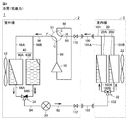
- FIG. 1 is a configuration diagram of an air conditioner 1 according to the present embodiment.
- the air conditioning apparatus 1 includes a compressor 10, an indoor heat exchanger 20, an expansion valve 30, an outdoor heat exchanger 40, and a four-way valve 91.
- the outdoor heat exchanger 40 includes a first heat exchange section 40A and a second heat exchange section 40B.
- the first heat exchanging section 40A and the second heat exchanging section 40B are, for example, the outdoor heat exchanger 40 divided into upper and lower parts.
- the indoor heat exchanger 20 includes a first heat exchange section 20A and a second heat exchange section 20B.
- the first heat exchanging unit 20A and the second heat exchanging unit 20B are, for example, the indoor heat exchanger 20 divided into two parts, that is, the upper and lower parts or the left and right parts.
- the outdoor unit 2 includes stop valves 110 and 112, a four-way valve 91, a compressor 10, an outdoor heat exchanger 40, an expansion valve 30, and pipes interconnecting these.
- the pipe 90 connects the port H of the four-way valve 91 and the stop valve 110 on the gas side.
- the pipe 92 connects the stop valve 112 on the liquid side and the expansion valve 30.
- the expansion valve 30 is arranged between the pipe 92 and the pipe 94.
- the pipe 94 branches into a pipe 94A and a pipe 94B from the middle, and connects the expansion valve 30 to the first heat exchange section 40A and the second heat exchange section 40B.
- a flow rate adjusting valve 34 is arranged at a branch portion between the pipe 94A and the pipe 94B.
- the discharge port and the suction port of the compressor 10 are connected to the ports G and E of the four-way valve 91 by pipes 99 and 98, respectively.
- One end of the pipe 96 is connected to the port F of the four-way valve 91, and the other end branches into pipes 96A and 96B from the middle.
- the branched pipes 96A and 96B are connected to the first heat exchange unit 40A and the second heat exchange unit 40B, respectively.
- the air conditioner 1 further includes a control device 200, a refrigerant pressure sensor (not shown), and a refrigerant temperature sensor.
- the control device 200 includes a communication circuit 201, a processor 202, and a memory 203.
- the memory 203 includes, for example, a ROM (Read Only Memory), a RAM (Random Access Memory), and a flash memory.
- the flash memory stores an operating system, application programs, and various data.
- the processor 202 controls the overall operation of the air conditioning apparatus 1.
- the functions of the control device 200 are realized by the processor 202 executing the operating system and application programs stored in the memory 203. When executing the application program, various data stored in the memory 203 are referenced.
- the communication circuit 201 is configured to transmit a control signal to the compressor 10, the four-way valve 91, the expansion valve 30, and the fan 42 flow rate adjusting valve 34 which are control targets.
- the communication circuit 201 is further configured to transmit a control signal to the fan 22 and the flow rate control valve 32 that are the control targets.
- the communication circuit 201 may be configured to receive a control signal from a remote controller (not shown) that remotely controls the control device 200.
- the control device 200 may be divided into a plurality of control units and arranged in the outdoor unit 2, the indoor unit 3, and the remote controller.
- each of the plurality of control units includes a processor.
- a plurality of processors cooperate to perform overall control of the air conditioner 1.
- the compressor 10 is configured to change the operating frequency according to a control signal received from the control device 200.
- the output of the compressor 10 is adjusted by changing the operating frequency of the compressor 10.
- Various types of compressors can be adopted, for example, rotary type, reciprocating type, scroll type, screw type, etc. can be adopted.
- the pipe 96 connects the first heat exchange unit 40A and the second heat exchange unit 40B to the port F of the four-way valve 91.
- the four-way valve 91 communicates with the pipe 99 and the pipe 96 to which the discharge port of the compressor 10 is connected as shown by the solid line during the cooling operation, and also to the pipe 98 and the pipe 98 to which the suction port of the compressor 10 is connected. Connect with 90.
- the four-way valve 91 connects the pipe 99 and the pipe 90 to which the discharge port of the compressor 10 is connected with each other as shown by a broken line during the heating operation, and also connects the pipe 98 and the pipe 98 to which the suction port of the compressor 10 is connected. 96 and communication.
- the indoor unit 3 includes an indoor heat exchanger 20, a fan 22, pipes 101 and 102, and a room temperature sensor 24.
- One end of the pipe 101 is branched into a pipe 101A and a pipe 101B from the middle, and the pipe 101A and the pipe 101B are connected to the first heat exchange unit 20A and the second heat exchange unit 20B, respectively.
- the other end of the pipe 101 is connected to the stop valve 110 by an extension pipe 100.
- the one end of the pipe 102 is branched into a pipe 102A and a pipe 102B from the middle, and is connected to the first heat exchange unit 20A and the second heat exchange unit 20B, respectively.
- a flow rate adjusting valve 32 is arranged at a branch portion between the pipe 102A and the pipe 102B.
- the other end of the pipe 102 is connected to the stop valve 112 by an extension pipe 103.
- the stop valves 110 and 112 are brought into communication with each other when the connection of the refrigerant circuit is completed during construction.
- the room temperature sensor 24 detects the room temperature and transmits it to the control device 200. It should be noted that the room temperature sensor 24 does not necessarily have to be arranged inside the indoor unit 3, and may be arranged in a remote controller or the like in the same room as the indoor unit 3.
- FIG. 2 is a diagram showing the flow of the refrigerant in the cooling operation during normal operation.
- the refrigerant flows in the direction shown by the arrow in FIG.
- the compressor 10 draws in and compresses the refrigerant from the pipe 90 via the four-way valve 91 and the pipe 98.
- the compressed refrigerant flows to the pipe 96 via the four-way valve 91.
- each heat exchanger functions as a condenser or an evaporator will be described together for easy understanding.
- the outdoor heat exchanger 40 condenses the refrigerant that has flowed into the pipe 96 from the compressor 10 via the four-way valve 91 and flows it into the pipe 94.
- the outdoor heat exchanger 40 (condenser) is configured so that the refrigerant, which has been discharged from the compressor 10 and has become high-temperature and high-pressure superheated steam, exchanges heat with the outside air to radiate heat. By this heat exchange, the refrigerant is condensed and liquefied near the outlet of the outdoor heat exchanger 40.
- the fan 42 is provided side by side with the outdoor heat exchanger 40 (condenser), and the control device 200 adjusts the rotation speed of the fan 42 by a control signal. By changing the rotation speed of the fan 42, the amount of heat exchange between the refrigerant and the outside air in the outdoor heat exchanger 40 (condenser) can be adjusted.
- the expansion valve 30 reduces the pressure of the refrigerant flowing from the outdoor heat exchanger 40 (condenser) to the pipe 94.
- the depressurized refrigerant flows into the pipe 92.
- the expansion valve 30 is configured so that the opening degree can be adjusted by a control signal received from the control device 200.
- the opening degree of the expansion valve 30 is changed to the closing direction, the refrigerant pressure on the outlet side of the expansion valve 30 decreases and the dryness of the refrigerant increases.
- the opening degree of the expansion valve 30 is changed to the opening direction, the refrigerant pressure at the outlet side of the expansion valve 30 increases and the dryness of the refrigerant decreases.
- the indoor heat exchanger 20 evaporates the refrigerant flowing from the expansion valve 30 to the pipe 92, the extension pipe 103, and the pipe 102.
- the evaporated refrigerant flows into the pipe 98 via the pipe 101, the extension pipe 100, the stop valve 110 and the four-way valve 91.
- the indoor heat exchanger 20 (evaporator) is configured such that the refrigerant decompressed by the expansion valve 30 exchanges heat with the indoor air to absorb heat. By this heat exchange, the refrigerant evaporates and becomes superheated steam near the outlet of the indoor heat exchanger 20.
- the fan 22 is attached to the indoor heat exchanger 20 (evaporator).
- the control device 200 adjusts the rotation speed of the fan 22 according to the control signal. By changing the rotation speed of the fan 22, the amount of heat exchange between the refrigerant and the indoor air in the indoor heat exchanger 20 (evaporator) can be adjusted.
- FIG. 3 is a PH diagram of the refrigeration cycle during operation when the amount of refrigerant is normal.
- the refrigerant is R32 will be described as an example.
- points A1 and A2 are compression processing by the compressor 10
- points A2 and A3 are condensation processing by a condenser
- points A3 and A4 are decompression by the expansion valve 30.
- the processing, point A4 to point A1 respectively correspond to the evaporation processing by the evaporator.
- the refrigerating capacity is a value obtained by multiplying the enthalpy difference dH between the points A1 and A4 by the refrigerant circulation amount Gr per unit time.
- the refrigerating capacity Q is expressed by the following equation (1), where enthalpy difference dH and refrigerant circulation amount Gr per unit time are given.
- FIG. 4 is a diagram showing the flow of the refrigerant in the cooling operation when the capacity is low.
- the state shown in FIG. 4 is different from the state shown in FIG. 2 in that the flow rate adjusting valve 34 limits the flow rate of the second heat exchange section 40B.
- the fan 42 continues to blow air.
- the liquefied refrigerant is not discharged while the refrigerant is condensed, so that the liquid refrigerant is stored inside the second heat exchange section 40B.
- the flow of the refrigerant in the other portions is the same as that in FIG. 2, and therefore the description will not be repeated in FIG.
- the flow rate adjusting valve 34 is configured not to completely close the pipe 94B side to ensure a minute flow rate.
- the two-phase refrigerant flows into the expansion valve 30 as the amount of circulating refrigerant decreases, it is preferable to use a valve having a larger diameter than the conventional one as the expansion valve 30.
- FIG. 5 is a PH diagram of the refrigeration cycle during operation when the refrigerant is stored in the heat exchanger.
- points B1 and B2 are compression processing by the compressor 10
- points B2 and B4 are condensation processing by a condenser
- points B4 and B5 are decompression by the expansion valve 30.
- Processing, point B5 to point B1 respectively correspond to the evaporation processing by the evaporator.
- the refrigerating capacity is a value obtained by multiplying the enthalpy difference dH between the points B1 and B5 by the refrigerant circulation amount Gr per unit time.
- Point B3 in FIG. 5 indicates the state of the outlet of the condenser (second heat exchange section 40B) in FIG.
- Point B4 in FIG. 5 shows the state of the outlet of the condenser (first heat exchange section 40A) in FIG.
- the enthalpy Hj after the two have joined together is given by the following equation using the enthalpies H40A and H40B at the outlets of the first heat exchange section 40A and the second heat exchange section 40B and the refrigerant flow rates Gr40A and Gr40B.
- Hj (H40A*Gr40A+H40B*Gr40B)/(Gr40A+Gr40B) That is, as shown in FIG. 5, when the pipe 94B side of the flow rate adjusting valve 34 is closed and the flow rate is small, the enthalpy Hj after the merging is substantially equal to the enthalpy H40A on the pipe 94A side with a large refrigerant flow rate. Further, the enthalpy at the point B4, that is, the enthalpy at the point B5 at the evaporator inlet can be adjusted by the flow rate of the refrigerant flowing to the pipe 94B side.
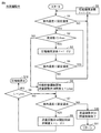
- FIG. 6 is a flowchart for explaining refrigerant storage control during the cooling operation.
- control device 200 determines whether the room temperature detected by room temperature sensor 24 is lower than the set temperature set by a remote controller or the like.
- the control device 200 determines in step S2 whether the operating frequency f of the compressor 10 is higher than the lower limit frequency fmin. If f>fmin (YES in S2), the control device 200 reduces the operating frequency f of the compressor 10 by ⁇ 2 in step S3 to reduce the cooling capacity of the air conditioner 1.
- step S4 the control device 200 determines whether or not the room temperature detected by the room temperature sensor 24 is lower than the set temperature set by the remote controller or the like. If the room temperature is less than the set temperature (YES in S4), the process returns to step S2. On the other hand, when the indoor temperature ⁇ the set temperature (NO in S4), in step S5, the control device 200 increases the operating frequency f of the compressor 10 by ⁇ 1 and increases the cooling capacity of the air conditioner 1.
- steps S1 to S5 are processes for adjusting the operating frequency of the compressor 10 by inverter control so that the air conditioning capacity of the air conditioner 1 in operation matches the air conditioning load.
- the process proceeds to the process of adjusting the refrigerant circulation amount after step S6. ..
- step S6 the operation of storing the refrigerant in the outdoor heat exchanger 40 is started.
- the control device 200 sets the opening degree L of the flow rate adjusting valve 34 that determines the flow rate of the second heat exchange section 40B to the maximum opening degree Lmax.
- the maximum opening Lmax is the opening L in the initial state.
- control device 200 determines whether or not the room temperature detected by room temperature sensor 24 is lower than the set temperature set by the remote controller or the like.
- step S8 the control device 200 narrows the opening degree L of the flow rate adjusting valve 34 by ⁇ 3 to store the liquid refrigerant in the second heat exchange section 40B. Increase the amount. As a result, the refrigerant circulation amount Gr decreases. Then, in step S9, the control device 200 determines whether or not the opening L of the flow rate adjusting valve 34 is the lower limit opening Lmin.
- step S7 When the opening L of the flow rate adjusting valve 34 is not the lower limit opening Lmin (NO in S9), the process of step S7 is executed again. If the indoor temperature is equal to or higher than the set temperature in step S7 (NO in S7), it is considered that there is no need to further reduce the cooling capacity and the air conditioning load and the air conditioning capacity are in balance, so that the flow rate adjustment valve 34 is opened in step S10. Control ends, and the process returns to the main routine in step S11.
- the control device 200 stops the compressor 10 in step S12. , Prevent the room temperature from dropping too low.
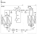
- FIG. 7 is the figure which showed the flow of the refrigerant
- the refrigerant flows in the direction shown by the arrow in FIG. 7.
- the compressor 10 draws in and compresses the refrigerant from the pipe 96 via the four-way valve 91 and the pipe 98.
- the compressed refrigerant flows to the pipe 90 via the four-way valve 91.
- each heat exchanger functions as a condenser or an evaporator will be described together for easy understanding.
- the indoor heat exchanger 20 condenses the refrigerant that has flowed into the pipe 101 from the compressor 10 via the four-way valve 91, the pipe 90, and the extension pipe 100 to flow into the pipe 102.
- the indoor heat exchanger 20 (condenser) is configured so that the refrigerant, which has been discharged from the compressor 10 and has become high-temperature and high-pressure superheated steam, exchanges heat with the indoor air to radiate heat. By this heat exchange, the refrigerant is condensed and liquefied near the outlet of the indoor heat exchanger 20.
- the fan 22 is attached to the indoor heat exchanger 20 (condenser), and the control device 200 adjusts the rotation speed of the fan 22 by a control signal. By changing the rotation speed of the fan 22, the amount of heat exchange between the refrigerant and the indoor air in the indoor heat exchanger 20 (condenser) can be adjusted.
- the expansion valve 30 reduces the pressure of the refrigerant flowing from the indoor heat exchanger 20 (condenser) to the pipe 92 via the pipe 102 and the extension pipe 103.
- the depressurized refrigerant flows to the pipe 94.
- the expansion valve 30 is configured so that the opening degree can be adjusted by a control signal received from the control device 200.
- the opening degree of the expansion valve 30 is changed to the closing direction, the refrigerant pressure on the outlet side of the expansion valve 30 decreases and the dryness of the refrigerant increases.
- the opening degree of the expansion valve 30 is changed to the opening direction, the refrigerant pressure at the outlet side of the expansion valve 30 increases and the dryness of the refrigerant decreases.
- the outdoor heat exchanger 40 evaporates the refrigerant flowing from the expansion valve 30 to the pipe 94.
- the evaporated refrigerant flows to the pipe 98 via the pipe 96 and the four-way valve 91.
- the outdoor heat exchanger 40 (evaporator) is configured such that the refrigerant decompressed by the expansion valve 30 exchanges heat with the outside air and absorbs heat. By this heat exchange, the refrigerant evaporates and becomes superheated steam near the outlet of the outdoor heat exchanger 40.
- the fan 42 is attached to the outdoor heat exchanger 40 (evaporator).
- the control device 200 adjusts the rotation speed of the fan 42 according to the control signal. By changing the rotation speed of the fan 42, the amount of heat exchange between the refrigerant and the outside air in the outdoor heat exchanger 40 (evaporator) can be adjusted.
- FIG. 8 is a diagram showing the flow of the refrigerant in the heating operation when the capacity is low.
- the state shown in FIG. 8 differs from the state shown in FIG. 7 in that the flow rate adjusting valve 32 limits the flow rate of the second heat exchange section 20B.
- the fan 22 continues to blow air.
- the liquefied refrigerant is not discharged while the refrigerant is condensed, so that the liquid refrigerant is stored inside the second heat exchange section 20B.
- the flow of the refrigerant in the other parts is the same as that in FIG. 7, and therefore the description will not be repeated in FIG.
- the flow rate adjusting valve 32 is configured not to completely close the pipe 102B side to ensure a minute flow rate.
- the PH diagram corresponding to FIG. 7 and the PH diagram corresponding to FIG. 8 differ from FIGS. 3 and 5 in the condensation temperature and the evaporation temperature, but when the refrigerant is R32, Regarding the point that the enthalpy difference is smaller in the operation shown in FIG. 8 than in FIG. 7, there is a tendency similar to the relationship in FIGS. 3 and 5.
- the condensing capacity can be kept smaller than before even in the case of heating.
- FIG. 9 is a flowchart for explaining refrigerant storage control during heating operation.
- control device 200 determines whether or not the room temperature detected by room temperature sensor 24 is higher than the set temperature set by a remote controller or the like.
- the control device 200 determines in step S12 whether the operating frequency f of the compressor 10 is higher than the lower limit frequency fmin. When f>fmin (YES in S12), the control device 200 reduces the operating frequency f of the compressor 10 by ⁇ 2 in step S13 to reduce the heating capacity of the air conditioner 1.
- step S14 the control device 200 determines whether or not the room temperature detected by the room temperature sensor 24 is higher than the set temperature set by the remote controller or the like. If the room temperature>the set temperature (YES in S14), the process returns to step S12. On the other hand, when the indoor temperature ⁇ the set temperature (NO in S14), the control device 200 increases the operating frequency f of the compressor 10 by ⁇ 1 and increases the heating capacity of the air conditioning device 1 in step S15.
- steps S11 to S15 are processes for adjusting the operating frequency of the compressor 10 by inverter control so that the air conditioning capacity of the air conditioner 1 in operation matches the air conditioning load.
- the operating frequency f becomes equal to or lower than the lower limit value fmin (NO in S12)
- it is impossible to suppress the air conditioning capacity by further lowering the operating frequency so that the process proceeds to the process of adjusting the refrigerant circulation amount after step S16. ..
- step S16 the operation of storing the refrigerant in the indoor heat exchanger 20 is started.
- the control device 200 sets the opening L of the flow rate adjusting valve 32 that determines the flow rate of the second heat exchange unit 20B to the maximum opening Lmax.
- the maximum opening Lmax is the opening L in the initial state.
- control device 200 determines whether or not the room temperature detected by room temperature sensor 24 is higher than the set temperature set by the remote controller or the like.
- step S18 the control device 200 narrows the opening degree L of the flow rate adjusting valve 32 by ⁇ 3 to store the liquid refrigerant in the second heat exchange section 20B. Increase the amount. Then, in step S19, the control device 200 determines whether or not the opening L of the flow rate adjusting valve 32 is the lower limit opening Lmin.
- step S17 When the opening L of the flow rate adjusting valve 32 is not the lower limit opening Lmin (NO in S19), the process of step S17 is executed again. If the indoor temperature is equal to or lower than the set temperature in step S17 (NO in S17), it is considered that there is no need to further reduce the heating capacity, and the air conditioning load and the air conditioning capacity are in balance, so the flow control valve 32 is opened in step S20. Control is completed, and the process returns to the main routine in step S21.
- the control device 200 stops the compressor 10 in step S22. , Prevent the room temperature from rising too high.
- FIG. 10 is a diagram showing the lower limit capabilities of the case where the control of the present embodiment is performed and the case where the normal control is performed, in comparison.
- the rated capacity is set to 100%
- the lower limit capacity when only the frequency control of the compressor 10 is executed is 15%
- the lower limit capacity when controlling the refrigerant storage amount was 10%.
- the lower limit capacity of the air conditioner of the present embodiment can be reduced to 66.7% compared to the normal machine.
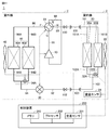
- FIG. 11 is a diagram showing a modified example in which the flow rate adjusting valve is modified.
- the flow rate adjusting valves 32 and 34 in FIG. 1 are changed to flow rate adjusting units 32A and 34A, respectively.
- the flow rate adjusting valves 32 and 34 are specifically intended to be three-way valves having a flow rate adjusting function.
- the amount of circulating refrigerant can be adjusted by slightly opening the three-way valve, so the adjustment range of the air-conditioning capacity can be increased by adjusting the compressor frequency and the three-way valve ( The lower limit capacity can be further reduced).
- the refrigerant is a compressor 10, a condenser (outdoor heat exchanger 40/indoor heat exchanger 20), an expansion device (expansion valve 30), and an evaporator (indoor heat exchanger 20/outdoor heat exchange).
- the air conditioner 1 that circulates in the order of the device 40).
- the condenser (outdoor heat exchanger 40/indoor heat exchanger 20) includes a first heat exchange section 40A/20A and a second heat exchange section 40B/20B configured to allow the refrigerant to flow in parallel with each other.
- a flow rate restricting unit (flow rate adjusting valve 34/32) configured to be able to make a flow rate difference between the flow rate of the refrigerant passing through the heat exchange section 40A/20A and the flow rate of the refrigerant passing through the second heat exchange section 40B/20B. ) And.
- the air conditioner 1 includes a control device 200 that controls the compressor 10 and the flow rate limiting unit (flow rate adjusting valve 34/32). The control device 200 uses the frequency and the flow rate difference of the compressor 10 in combination when changing the air conditioning capacity of the air conditioner 1.
- the expansion device corresponds to the expansion valve 30, but is not necessarily a valve and may be, for example, a capillary tube.
- the refrigerant circulation amount can be increased or decreased without using a refrigerant container such as an accumulator and a receiver, and the lower limit capacity can be used. Can be kept small. Further, even when using a refrigerant container such as an accumulator and a receiver, a small size is sufficient.
- the control device 200 reduces the frequency f of the compressor 10 when changing (a) the air conditioning capacity from the first capacity to the second capacity that is smaller than the first capacity, and (b) sets the air conditioning capacity to the first capacity.
- the flow rate of the refrigerant passing through the second heat exchange section 40B/20B is changed by the flow rate restriction section (flow rate adjusting valve 34/32) to the first heat exchange section.
- Changing the operating frequency of the compressor 10 to lower the air conditioning capacity has better response than lowering the air conditioning capacity by increasing the refrigerant storage amount by the flow rate limiting unit. Therefore, when lowering the air conditioning capacity, it is better to lower the air conditioning capacity by lowering the operating frequency first, and at the same time or after that, increasing the refrigerant storage amount by the flow rate limiting unit to lower the air conditioning capacity, and the fluctuation of room temperature can be small. ..
- the air conditioner 1 further includes a four-way valve 91 that switches the circulation direction of the refrigerant between cooling operation and heating operation.
- the indoor heat exchanger 20 and the outdoor heat exchanger 40 are both divided into two.
- the outdoor heat exchanger 40 functions as a condenser during the cooling operation, and the indoor heat exchanger 20 functions as a condenser during the heating operation.
- one of the flow paths of the flow rate adjusting valve 34 arranged on the outdoor heat exchanger 40 side is closed. Since the fan 42 of the outdoor heat exchanger 40 is rotating, the refrigerant is stored in the heat exchanger on the closed side (the second heat exchange unit 40B in FIG. 4).
- one of the flow paths of the flow rate adjusting valve 32 arranged on the indoor heat exchanger 20 side is closed. Since the fan of the indoor heat exchanger 20 is rotating, the refrigerant is stored in the heat exchanger on the closed side (the second heat exchange section 20B in FIG. 8).
- one of the features is that the rotation of the condenser fan is maintained in order to positively let the refrigerant lie in the heat exchanger in order to reduce the air conditioning capacity.
- the fan of the condenser in the outdoor heat exchanger, in the normal configuration, is one fan shared by the two divided heat exchange sections.
- the fan of the condenser In the indoor heat exchanger, the fan of the condenser is one fan that is common to the line flow fan, but in the case of a configuration having two propeller fans on the left and right, both fans will rotate.
Landscapes
- Engineering & Computer Science (AREA)
- Physics & Mathematics (AREA)
- Mechanical Engineering (AREA)
- Thermal Sciences (AREA)
- General Engineering & Computer Science (AREA)
- Air Conditioning Control Device (AREA)
Abstract
La présente invention concerne un conditionneur d'air (1), pour lequel, pendant le fonctionnement, un fluide frigorigène circule à travers un compresseur (10), un condenseur (40/20), un dispositif d'expansion (30) et un évaporateur (20/40) dans l'ordre indiqué. Le condenseur (40/20) comprend une première unité d'échangeur de chaleur (40A/20A) et une seconde unité d'échangeur de chaleur (40B/20B) qui sont configurées pour canaliser le fluide frigorigène parallèlement l'une par rapport à l'autre, et une unité de limitation de débit (34/32) configurée de sorte à pouvoir produire une différence de débit entre le débit du fluide frigorigène passant à travers la première unité d'échangeur de chaleur (40A/20A) et le débit du fluide frigorigène passant à travers la seconde unité d'échangeur de chaleur (40B/20B). Le conditionneur d'air (1) comprend un dispositif de commande (200) pour commander le compresseur (10) et l'unité de limitation de débit (34/32). Lors du changement de la performance de climatisation du conditionneur d'air (1), le dispositif de commande (200) utilise, en combinaison, la fréquence du compresseur (10) et la différence de débit du fluide frigorigène passant à travers les deux unités d'échangeur de chaleur.
Priority Applications (5)
| Application Number | Priority Date | Filing Date | Title |
|---|---|---|---|
| CN201980088167.9A CN113302436A (zh) | 2019-01-28 | 2019-01-28 | 空气调节装置 |
| EP19912296.1A EP3919835A4 (fr) | 2019-01-28 | 2019-01-28 | Conditionneur d'air |
| JP2020568881A JP7086231B2 (ja) | 2019-01-28 | 2019-01-28 | 空気調和装置 |
| US17/288,999 US20210404710A1 (en) | 2019-01-28 | 2019-01-28 | Air conditioner |
| PCT/JP2019/002650 WO2020157788A1 (fr) | 2019-01-28 | 2019-01-28 | Conditionneur d'air |
Applications Claiming Priority (1)
| Application Number | Priority Date | Filing Date | Title |
|---|---|---|---|
| PCT/JP2019/002650 WO2020157788A1 (fr) | 2019-01-28 | 2019-01-28 | Conditionneur d'air |
Publications (1)
| Publication Number | Publication Date |
|---|---|
| WO2020157788A1 true WO2020157788A1 (fr) | 2020-08-06 |
Family
ID=71840182
Family Applications (1)
| Application Number | Title | Priority Date | Filing Date |
|---|---|---|---|
| PCT/JP2019/002650 Ceased WO2020157788A1 (fr) | 2019-01-28 | 2019-01-28 | Conditionneur d'air |
Country Status (5)
| Country | Link |
|---|---|
| US (1) | US20210404710A1 (fr) |
| EP (1) | EP3919835A4 (fr) |
| JP (1) | JP7086231B2 (fr) |
| CN (1) | CN113302436A (fr) |
| WO (1) | WO2020157788A1 (fr) |
Cited By (2)
| Publication number | Priority date | Publication date | Assignee | Title |
|---|---|---|---|---|
| WO2024075235A1 (fr) * | 2022-10-06 | 2024-04-11 | 三菱電機株式会社 | Dispositif de climatisation |
| WO2025041437A1 (fr) * | 2023-08-22 | 2025-02-27 | 株式会社デンソー | Dispositif à cycle de réfrigération |
Families Citing this family (1)
| Publication number | Priority date | Publication date | Assignee | Title |
|---|---|---|---|---|
| KR102887221B1 (ko) | 2022-10-31 | 2025-11-14 | 엘지전자 주식회사 | 공기조화기 |
Citations (3)
| Publication number | Priority date | Publication date | Assignee | Title |
|---|---|---|---|---|
| JPS5639664B2 (fr) | 1974-05-15 | 1981-09-14 | ||
| JPS6144259A (ja) * | 1984-08-09 | 1986-03-03 | 株式会社日立製作所 | 空気調和機 |
| JPS646657A (en) * | 1987-06-26 | 1989-01-11 | Matsushita Refrigeration | Multiple chamber type air conditioner |
Family Cites Families (13)
| Publication number | Priority date | Publication date | Assignee | Title |
|---|---|---|---|---|
| JP2908013B2 (ja) * | 1990-07-31 | 1999-06-21 | 株式会社東芝 | 空気調和機 |
| JP2922002B2 (ja) * | 1991-02-20 | 1999-07-19 | 株式会社東芝 | 空気調和機 |
| JPH0861799A (ja) * | 1994-08-26 | 1996-03-08 | Sharp Corp | 空気調和機 |
| JPH09229500A (ja) * | 1995-12-27 | 1997-09-05 | Mando Mach Co Ltd | 多室エアコン |
| JP4151625B2 (ja) * | 2004-07-21 | 2008-09-17 | 松下電器産業株式会社 | 空気調和機 |
| JP5125124B2 (ja) * | 2007-01-31 | 2013-01-23 | ダイキン工業株式会社 | 冷凍装置 |
| WO2010082325A1 (fr) * | 2009-01-15 | 2010-07-22 | 三菱電機株式会社 | Appareil de conditionnement d'air |
| WO2012014345A1 (fr) * | 2010-07-29 | 2012-02-02 | 三菱電機株式会社 | Pompe à chaleur |
| US10775060B2 (en) * | 2013-10-24 | 2020-09-15 | Mitsubishi Electric Corporation | Air-conditioning apparatus |
| US10018388B2 (en) * | 2014-02-27 | 2018-07-10 | Mitsubishi Electric Corporation | Heat source side unit and refrigeration cycle apparatus |
| WO2015132966A1 (fr) * | 2014-03-07 | 2015-09-11 | 三菱電機株式会社 | Dispositif à cycle de réfrigération |
| CN206944520U (zh) * | 2017-06-20 | 2018-01-30 | 深圳市英维克科技股份有限公司 | 一种制冷系统 |
| US10753663B2 (en) * | 2018-01-25 | 2020-08-25 | Johnson Controls Technology Company | HVAC system with multiple compressors and heat exchangers |
-
2019
- 2019-01-28 WO PCT/JP2019/002650 patent/WO2020157788A1/fr not_active Ceased
- 2019-01-28 CN CN201980088167.9A patent/CN113302436A/zh active Pending
- 2019-01-28 JP JP2020568881A patent/JP7086231B2/ja not_active Expired - Fee Related
- 2019-01-28 EP EP19912296.1A patent/EP3919835A4/fr not_active Withdrawn
- 2019-01-28 US US17/288,999 patent/US20210404710A1/en not_active Abandoned
Patent Citations (3)
| Publication number | Priority date | Publication date | Assignee | Title |
|---|---|---|---|---|
| JPS5639664B2 (fr) | 1974-05-15 | 1981-09-14 | ||
| JPS6144259A (ja) * | 1984-08-09 | 1986-03-03 | 株式会社日立製作所 | 空気調和機 |
| JPS646657A (en) * | 1987-06-26 | 1989-01-11 | Matsushita Refrigeration | Multiple chamber type air conditioner |
Non-Patent Citations (1)
| Title |
|---|
| See also references of EP3919835A4 |
Cited By (2)
| Publication number | Priority date | Publication date | Assignee | Title |
|---|---|---|---|---|
| WO2024075235A1 (fr) * | 2022-10-06 | 2024-04-11 | 三菱電機株式会社 | Dispositif de climatisation |
| WO2025041437A1 (fr) * | 2023-08-22 | 2025-02-27 | 株式会社デンソー | Dispositif à cycle de réfrigération |
Also Published As
| Publication number | Publication date |
|---|---|
| CN113302436A (zh) | 2021-08-24 |
| US20210404710A1 (en) | 2021-12-30 |
| JP7086231B2 (ja) | 2022-06-17 |
| EP3919835A1 (fr) | 2021-12-08 |
| JPWO2020157788A1 (ja) | 2021-10-14 |
| EP3919835A4 (fr) | 2022-01-19 |
Similar Documents
| Publication | Publication Date | Title |
|---|---|---|
| US6779356B2 (en) | Apparatus and method for controlling operation of air conditioner | |
| CN110337570B (zh) | 空调装置 | |
| CN113454408B (zh) | 空气调节装置 | |
| JP4725387B2 (ja) | 空気調和装置 | |
| WO2013145006A1 (fr) | Dispositif de conditionnement d'air | |
| EP3492839A1 (fr) | Dispositif à cycle de réfrigération | |
| CN114127479B (zh) | 制冷装置 | |
| JP4457928B2 (ja) | 冷凍装置 | |
| KR20210026645A (ko) | 공기 조화기 및 그 제어 방법 | |
| JP7086231B2 (ja) | 空気調和装置 | |
| KR20170074990A (ko) | 공기 조화 장치 | |
| WO2015140994A1 (fr) | Unité côté source de chaleur et climatiseur | |
| US8769968B2 (en) | Refrigerant system and method for controlling the same | |
| WO2016002021A1 (fr) | Dispositif de climatisation | |
| JP6707698B2 (ja) | 空気調和システムの制御装置および制御方法ならびに空気調和システム | |
| WO2020262624A1 (fr) | Dispositif de réfrigération | |
| WO2017094172A1 (fr) | Dispositif de climatisation | |
| US12480696B2 (en) | Refrigeration cycle apparatus | |
| US20250067463A1 (en) | Air conditioner | |
| WO2024176371A1 (fr) | Dispositif de climatisation | |
| JP2019095128A (ja) | ヒートポンプ装置の制御方法、及びヒートポンプ装置 | |
| JP6847022B2 (ja) | ヒートポンプ装置の制御方法、及びヒートポンプ装置 | |
| JP6507598B2 (ja) | 空調システム | |
| JP2020143879A (ja) | 空気調和機 | |
| JP7367213B2 (ja) | 冷凍サイクル装置の制御方法 |
Legal Events
| Date | Code | Title | Description |
|---|---|---|---|
| 121 | Ep: the epo has been informed by wipo that ep was designated in this application |
Ref document number: 19912296 Country of ref document: EP Kind code of ref document: A1 |
|
| ENP | Entry into the national phase |
Ref document number: 2020568881 Country of ref document: JP Kind code of ref document: A |
|
| NENP | Non-entry into the national phase |
Ref country code: DE |
|
| ENP | Entry into the national phase |
Ref document number: 2019912296 Country of ref document: EP Effective date: 20210830 |