WO2020158040A1 - Émetteur satellite et système de communication par satellite relais - Google Patents
Émetteur satellite et système de communication par satellite relais Download PDFInfo
- Publication number
- WO2020158040A1 WO2020158040A1 PCT/JP2019/036951 JP2019036951W WO2020158040A1 WO 2020158040 A1 WO2020158040 A1 WO 2020158040A1 JP 2019036951 W JP2019036951 W JP 2019036951W WO 2020158040 A1 WO2020158040 A1 WO 2020158040A1
- Authority
- WO
- WIPO (PCT)
- Prior art keywords
- papr
- satellite
- relative phase
- inter
- excitation coefficient
- Prior art date
- Legal status (The legal status is an assumption and is not a legal conclusion. Google has not performed a legal analysis and makes no representation as to the accuracy of the status listed.)
- Ceased
Links
Images




Classifications
-
- H—ELECTRICITY
- H04—ELECTRIC COMMUNICATION TECHNIQUE
- H04B—TRANSMISSION
- H04B7/00—Radio transmission systems, i.e. using radiation field
- H04B7/14—Relay systems
- H04B7/15—Active relay systems
- H04B7/185—Space-based or airborne stations; Stations for satellite systems
- H04B7/1853—Satellite systems for providing telephony service to a mobile station, i.e. mobile satellite service
- H04B7/18539—Arrangements for managing radio, resources, i.e. for establishing or releasing a connection
- H04B7/18543—Arrangements for managing radio, resources, i.e. for establishing or releasing a connection for adaptation of transmission parameters, e.g. power control
-
- H—ELECTRICITY
- H04—ELECTRIC COMMUNICATION TECHNIQUE
- H04B—TRANSMISSION
- H04B1/00—Details of transmission systems, not covered by a single one of groups H04B3/00 - H04B13/00; Details of transmission systems not characterised by the medium used for transmission
- H04B1/02—Transmitters
- H04B1/04—Circuits
- H04B1/0458—Arrangements for matching and coupling between power amplifier and antenna or between amplifying stages
-
- H—ELECTRICITY
- H04—ELECTRIC COMMUNICATION TECHNIQUE
- H04B—TRANSMISSION
- H04B7/00—Radio transmission systems, i.e. using radiation field
- H04B7/02—Diversity systems; Multi-antenna system, i.e. transmission or reception using multiple antennas
- H04B7/04—Diversity systems; Multi-antenna system, i.e. transmission or reception using multiple antennas using two or more spaced independent antennas
- H04B7/06—Diversity systems; Multi-antenna system, i.e. transmission or reception using multiple antennas using two or more spaced independent antennas at the transmitting station
- H04B7/0613—Diversity systems; Multi-antenna system, i.e. transmission or reception using multiple antennas using two or more spaced independent antennas at the transmitting station using simultaneous transmission
- H04B7/0615—Diversity systems; Multi-antenna system, i.e. transmission or reception using multiple antennas using two or more spaced independent antennas at the transmitting station using simultaneous transmission of weighted versions of same signal
- H04B7/0617—Diversity systems; Multi-antenna system, i.e. transmission or reception using multiple antennas using two or more spaced independent antennas at the transmitting station using simultaneous transmission of weighted versions of same signal for beam forming
-
- H—ELECTRICITY
- H04—ELECTRIC COMMUNICATION TECHNIQUE
- H04B—TRANSMISSION
- H04B7/00—Radio transmission systems, i.e. using radiation field
- H04B7/14—Relay systems
- H04B7/15—Active relay systems
- H04B7/185—Space-based or airborne stations; Stations for satellite systems
- H04B7/1851—Systems using a satellite or space-based relay
- H04B7/18515—Transmission equipment in satellites or space-based relays
-
- H—ELECTRICITY
- H04—ELECTRIC COMMUNICATION TECHNIQUE
- H04B—TRANSMISSION
- H04B7/00—Radio transmission systems, i.e. using radiation field
- H04B7/14—Relay systems
- H04B7/15—Active relay systems
- H04B7/204—Multiple access
- H04B7/2041—Spot beam multiple access
-
- H—ELECTRICITY
- H04—ELECTRIC COMMUNICATION TECHNIQUE
- H04L—TRANSMISSION OF DIGITAL INFORMATION, e.g. TELEGRAPHIC COMMUNICATION
- H04L27/00—Modulated-carrier systems
- H04L27/26—Systems using multi-frequency codes
- H04L27/2601—Multicarrier modulation systems
- H04L27/2614—Peak power aspects
- H04L27/2621—Reduction thereof using phase offsets between subcarriers
-
- H—ELECTRICITY
- H04—ELECTRIC COMMUNICATION TECHNIQUE
- H04B—TRANSMISSION
- H04B7/00—Radio transmission systems, i.e. using radiation field
- H04B7/14—Relay systems
- H04B7/15—Active relay systems
- H04B7/204—Multiple access
- H04B7/208—Frequency-division multiple access [FDMA]
-
- H—ELECTRICITY
- H04—ELECTRIC COMMUNICATION TECHNIQUE
- H04W—WIRELESS COMMUNICATION NETWORKS
- H04W84/00—Network topologies
- H04W84/02—Hierarchically pre-organised networks, e.g. paging networks, cellular networks, WLAN [Wireless Local Area Network] or WLL [Wireless Local Loop]
- H04W84/04—Large scale networks; Deep hierarchical networks
- H04W84/06—Airborne or Satellite Networks
Definitions
- the present invention relates to a satellite transmitter and a relay satellite communication system for suppressing the peak power of a transmitting antenna element.
- BFN beamforming network
- Beamforming methods include microwave beamforming (MBF) that uses a microwave phase shifter and digital beamforming (DBF) that controls the excitation coefficient by digital signal processing.
- MBF microwave beamforming
- DBF digital beamforming
- the number of beams can be expected to be increased in digital beam forming because the beams can be integrated as compared with microwave beam forming.
- a technique related to a relay device that forms a beam by performing product-sum calculation using a weighting coefficient for each beam in a digital beam former after frequency-dividing a received beam (for example, , Patent Document 1).
- the power consumption in digital processing is reduced by not performing the DBF calculation at the frequency with no input signal. Further, the digital beam forming method used in the relay device according to Patent Document 1 can be applied to the transmission beam as it is, and the same effect can be expected in the transmitter.
- the conventional relay device according to Patent Document 1 forms a beam by setting the above-described configuration and setting an excitation coefficient corresponding to a beam in each element for each band of each beam regardless of the modulation method. Have a function. Further, the conventional relay device according to Patent Document 1 is capable of flexibly forming a beam even when the occupied band of the beam changes.
- the transmitter is equipped with an amplifier that amplifies the transmission power.
- an amplifier that amplifies the transmission power.
- it is necessary to take a large back-off margin in order to avoid the non-linear distortion caused by using the non-linear region in the amplifier. This suppresses the usable dynamic range of the amplifier.
- orthogonal frequency division multiplexing OFDM
- orthogonal frequency division multiplexing orthogonal frequency division multiplexing method
- PAPR Peak to Average Power Ratio
- the PTS method is an advantageous method in that it can suppress peaks without causing distortion of a transmission signal (see, for example, Non-Patent Document 1).
- the PTS method divides the multi-carrier into several clusters in the frequency domain and then converts the divided multi-carriers from the frequency domain to the time domain by IFFT (Inverse: Fast Inverse Fourier Transform). Further, in the PTS method, PAPR can be suppressed by adding an appropriate phase between the clusters in the time domain and then multiplexing the clusters. In the PTS method, by sharing the phase provided between the clusters with the receiver side, the entire multicarrier can be restored at the time of demodulation.
- IFFT Inverse: Fast Inverse Fourier Transform
- the excitation coefficient can be set independently for each element and each beam.
- the phase of the composite wavefront emitted from the transmitting antenna array is controlled, and a beam is formed.
- the beam formation can be performed by setting the excitation coefficient corresponding to the beam to each element for each band of the beam regardless of the modulation method.
- signals in all bands forming different beams pass through the same element, and like the multi-carrier transmitter, the PAPR is used. Will increase. Therefore, it is necessary to secure a large back-off margin of the transmission amplifier. Therefore, the conventional relay device according to Patent Document 1 has a problem that the transmission power is limited.
- Non-Patent Document 1 when demodulating a multicarrier by a single receiver, phase control information added between clusters for suppressing PAPR is transmitted from the transmitter side. There was a problem that the receiver side had to share it by another method.
- the present invention has been made in order to solve the above-mentioned problems, the limitation of transmission power is suppressed, and it is not necessary to share phase control information between the transmitter side and the receiver side.
- the purpose is to obtain a satellite transmitter and a relay satellite communication system.
- the satellite transmitter according to the present invention based on each of the K analog signals, has K transmitting antenna elements that radiate transmission beams having different frequencies to one or more arbitrary points on the ground, and separates for each frequency.
- the frequency domain digital signals being waved are input as K corresponding to the number of transmitting antenna elements, and each of the K digital signals is multiplexed on the frequency axis and then converted into a time domain digital signal.
- a multiplexing unit a digital-analog converter for converting each of the K digital signals into an analog signal, and a storage device for storing K excitation coefficients for forming a transmission beam as the beam forming excitation coefficients
- a PAPR calculation unit that calculates a peak-to-average power ratio for each of the K digital signals converted by the multiplexing unit as PAPR, and an inter-beam relative phase that suppresses the peak power of the transmitting antenna element based on the K PAPRs.
- the excitation coefficient calculation section for calculating K updated excitation coefficients based on the inter-beam relative phase and the beam forming excitation coefficient, and for the received relay signal
- An excitation coefficient multiplication unit that multiplies each of the K updated excitation coefficients in the frequency domain to generate a frequency domain digital signal to be output to the multiplexing unit.
- the satellite transmitter according to the present invention based on each of the K analog signals, is divided into K transmission antenna elements that radiate a transmission beam to spatially different M points on the ground, and demultiplexed for each frequency.
- a frequency-domain digital signal is input as K corresponding to the number of transmitting antenna elements, each K digital signal is multiplexed on the frequency axis, and then converted into a time-domain digital signal.
- a digital-analog converter for converting each of the K digital signals into an analog signal
- a storage device for storing the K excitation coefficients for forming a transmission beam as beam forming excitation coefficients
- a multiplexing unit for converting each of the K digital signals into an analog signal.
- the PAPR calculation unit that calculates the peak-to-average power ratio for each of the K digital signals converted by the unit as PAPR, and the inter-beam relative phase that suppresses the peak power of the transmitting antenna element based on the K PAPRs.
- An inter-beam relative phase calculation section for calculating, an excitation coefficient calculation section for calculating K updated excitation coefficients based on the inter-beam relative phase and the beam forming excitation coefficient, and a frequency for the received relay signal.
- An excitation coefficient multiplication unit that generates a digital signal in the frequency domain to be output to the multiplexing unit by multiplying K updated excitation coefficients in the region, a storage device, an excitation coefficient calculation unit, and M DBF transmitters having an excitation coefficient multiplication unit are provided, the relay signals are configured as individual M relay signals, and the M DBF transmitters are configured as individual M relay signals. Based on each of the relay signals, M digital signals in the frequency domain are output, and the multiplexing unit generates the K digital signals after the summation by summing the M digital signals in the frequency domain for each frequency.
- each of the K digital signals after the summation is combined on the frequency axis and converted into a digital signal in the time domain, and the inter-beam relative phase calculation unit calculates the inter-beam relative phase by M DBFs.
- the data is output to each of the transmitters.
- a relay satellite communication system is configured to include a ground gateway station, a communication control station, and a ground satellite control station provided on the ground, and a satellite repeater having a satellite receiver and a satellite transmitter.
- the communication control station generates a relay signal, and relates to each of the time domain digital signals of each element of the transmission antenna elements provided in the satellite transmitter with respect to the generated relay signal.
- the peak-to-average power ratio is calculated as PAPR
- the inter-beam relative phase that suppresses the peak power of the transmission antenna element is calculated based on PAPR
- the beam of the transmission beam emitted from the satellite transmitter is calculated based on the inter-beam relative phase.
- the updated excitation coefficient is calculated, and the ground gateway station communicates with the communication control station.
- the relay signal generated by the satellite receiver is transmitted by the satellite receiver, the ground satellite control station transmits the updated excitation coefficient generated by the communication control station to the satellite transmitter, and the satellite receiver receives it from the ground gateway station.
- a frequency-domain digital signal that is demultiplexed for each frequency is generated from the relay signal, and the satellite transmitter has different frequencies at one or more arbitrary points on the ground based on each of the K analog signals.
- After the wave it combines the signal to convert it into a digital signal in the time domain, the digital-analog converter that converts each of the K digital signals into an analog signal, and receives the updated excitation coefficient from the ground satellite control station.
- An excitation for generating an updated frequency domain digital signal for output to the multiplexing unit by multiplying the frequency domain digital signal generated by the satellite receiver by the updated excitation coefficient in the frequency domain And a coefficient multiplication unit.
- the inter-beam relative phase that suppresses the peak power of the transmitting antenna element is calculated based on the PAPR calculation result, and the excitation coefficient is updated using the calculated inter-beam relative phase.
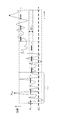
- FIG. 1 is a diagram showing an internal configuration of a satellite transmitter according to a first embodiment of the present invention.
- FIG. 3 is a schematic diagram of a relay signal input to the satellite transmitter according to the first embodiment of the present invention.
- FIG. 3 is a diagram showing a first configuration example in which a relay signal is input from a satellite receiver to the satellite transmitter according to the first embodiment of the present invention.
- FIG. 6 is a diagram showing a second configuration example in which a relay signal is input from a satellite receiver to the satellite transmitter according to the first embodiment of the present invention. It is a conceptual diagram for demonstrating the function of the switch which concerns on Embodiment 1 of this invention.
- FIG. 7 is a flowchart showing a series of processes executed in a PAPR calculation unit and an inter-beam relative phase calculation unit in the first embodiment of the present invention.
- FIG. 5 is a diagram showing an outline of a real-time signal input to a PAPR calculation unit in the first embodiment of the present invention. It is the figure which showed the internal structure of the satellite transmitter which concerns on Embodiment 2 of this invention. It is a schematic diagram of the relay signal input into the satellite transmitter which concerns on Embodiment 2 of this invention. It is a figure which shows the structural example of the relay satellite communication system containing the satellite repeater which concerns on Embodiment 3 of this invention. It is a schematic diagram of a communication control station according to a third embodiment of the present invention.
- FIG. 1 is a diagram showing an internal configuration of a satellite transmitter according to the first embodiment of the present invention.
- the satellite transmitter according to the first embodiment shown in FIG. 1 is intended to simultaneously transmit the transmission beams 16a to 16d as communication signals to one or more points m.
- Transmit beam 16a Transmit beam to Point 1
- Transmit beam 16b Transmit beam to Point 2
- Transmit beam 16c Transmit beam to Point m
- Transmit beam 16d Transmit beam to Point M
- the satellite transmitter 1 includes a DBF transmitter 2, multiplexers 12a to 12d, digital-analog converters (hereinafter referred to as DACs) 13a to 13d, amplifiers 14a to 14d, transmitting antenna elements 15a to 15d, PAPR calculator. 18 and an inter-beam relative phase calculation unit 19. Further, the DBF transmission unit 2 includes excitation coefficient multiplication units 11a to 11d, a storage device 17, and an excitation coefficient calculation unit 20.
- DACs digital-analog converters
- Each of the excitation coefficient multiplication units 11a to 11d in the DBF transmission unit 2 multiplies the received relay signal 51 by the excitation coefficient in the frequency domain.
- the multiplexing units 12a to 12d multiplex the relay signal, which is frequency-divided after being multiplied by the excitation coefficient, into a signal in the time domain.
- the DACs 13a to 13d convert the relay signal after being multiplexed by the multiplexing units 12a to 12d from a digital signal to an analog signal.
- the amplifiers 14a to 14d amplify the relay signals that have been converted into analog signals by the DACs 13a to 13d.
- the transmission antenna elements 15a to 15d are configured with the number of elements K. Here, K is an integer of 1 or more. Then, the transmitting antenna elements 15a to 15d radiate the relay signals amplified by the amplifiers 14a to 14d into space as radio waves.
- the PAPR calculator 18 calculates PAPR, which is the peak-to-average power ratio of each relay signal multiplexed by the multiplexers 12a to 12d.
- the inter-beam relative phase calculation unit 19 determines the relative phase between the beams based on the information regarding the PAPR calculated by the PAPR calculation unit 18.
- the storage device 17 in the DBF transmission unit 2 is a memory that stores the excitation coefficient used for beam forming. Further, the excitation coefficient calculation unit 20 in the DBF transmission unit 2 updates the beam forming excitation coefficient stored in the storage device 17 and the inter-beam phase information determined by the inter-beam relative phase calculation unit, after the update. Calculate the excitation coefficient of. Then, each of the excitation coefficient multiplication units 11a to 11d uses the excitation coefficient updated by the excitation coefficient calculation unit 20 to perform the multiplication process on the relay signal 51.
- the satellite transmitter 1 suppresses the PAPR of the signals input to the amplifiers 14a to 14d and reduces the backoff of the amplifiers 14a to 14d. It has a function of improving the outputs of the transmission beams 16a to 16d.
- FIG. 2 is a schematic diagram of the relay signal 51 input to the satellite transmitter 1 according to the first embodiment of the present invention.
- the relay signal 51 is a digital signal, and is a signal obtained by demultiplexing the signal in the total band ⁇ f with the resolution in the band ⁇ fch.
- the band ⁇ fch having the minimum resolution is called a sub-channel.
- Each subchannel has digital values of amplitude and phase.
- the number of sub-channels is N channels.
- N is an integer of 1 or more.
- relay signals transmitted as a total of M transmission beams 16a to 16d are band-divided and included in the total band ⁇ f as shown in FIG.
- FIG. 2 illustrates the case where the bands corresponding to the respective beams occupy the sub-channels in the order of the beam numbers.
- the bands corresponding to the beams do not have to be in the order shown in FIG.
- the total band of all beams may be equal to or less than the total band ⁇ f, and may not completely occupy the total band ⁇ f.
- FIG. 1 shows a case where there is one DBF transmission unit 2, and in this case, each of the M transmission beams 16a to 16d does not share the same sub-channel. That is, the frequencies are always different between the beams.
- relay signal 51 is described as a vector X, it becomes as shown in the following equation (1).
- Xn is the complex amplitude of subchannel n.
- the complex amplitude of the subchannel n belonging to the beam m is represented by Xn,m.
- a cluster corresponding to a set of complex amplitudes of sub-channels forming the beam m is represented by a vector xm.
- FIG. 3 is a diagram showing a first configuration example in which the relay signal 51 is input from the satellite receiver 31 to the satellite transmitter 1 according to the first embodiment of the present invention. Specifically, FIG. 3 shows a configuration in which the relay signal 51 generated by the satellite receiver 31 is input to the satellite transmitter 1 based on the relay signal 53 transmitted from the ground gateway station 52. ing.
- the ground gateway station 52 allocates the data to be transmitted to the M point by the satellite transmitter 1 to the M clusters in the total band ⁇ f as shown in the above equation (1) and transmits it to the satellite receiver 31 as real-time data. ..
- the satellite receiver 31 includes a receiving antenna 45, an ADC 43, and a demultiplexing unit 42.
- the ADC 43 generates a real-time digital signal by subjecting the relay signal 53 received via the receiving antenna 45 to analog-digital conversion (Analog Digital Convert: ADC).
- the demultiplexing unit 42 generates a relay signal 51 by demultiplexing the digitally converted real-time digital signal into a band ⁇ fch that is a subchannel in the frequency domain.
- the relay signal 51 generated by being demultiplexed can be expressed by the above equation (1).
- the terrestrial satellite control station 54 transmits, as a command signal 55, information on the beam forming excitation coefficient related to the transmission beam forming of the relay signal 51 to the satellite transmitter 1.
- the satellite transmitter 1 stores the command signal received by the command receiving antenna 56 in the storage device 17.
- the relay signal 51 and the beam forming excitation coefficient required for setting the transmission beam are controlled from the ground.
- the details of the beam forming excitation coefficient will be described later.
- FIG. 4 is a diagram showing a second configuration example in which the relay signal 51 is input from the satellite receiver 31 to the satellite transmitter 1 according to the first embodiment of the present invention. Specifically, in FIG. 4, the relay signal 51 generated by the satellite receiver 31 by receiving the beams transmitted from a plurality of ground stations as the reception beams 46A to 46D is input to the satellite transmitter 1. The structure is shown.
- the satellite repeater 200 shown in FIG. 4 includes a satellite receiver 31, a switch 48, a satellite transmitter 1, a command receiving antenna 56, and a satellite control unit 60.
- the satellite receiver 31 includes a DBF receiver 32, demultiplexers 42A to 42D, analog-digital converters (hereinafter referred to as ADCs) 43A to 43D, amplifiers 44A to 44D, receiving antenna elements 45A to 45D, and a vector combiner. It is configured with 47. Further, the DBF receiving unit 32 includes excitation coefficient multiplying units 41A to 41D and a storage device 49.
- ADCs analog-digital converters
- the satellite repeater 200 shown in FIG. 4 simultaneously receives reception beams 46A to 46D, which are communication signals from M'points of points 1'to M'.
- the satellite repeater 200 replaces each communication signal and synthesizes/separates bands.
- the satellite repeater 200 then forms M transmission beams 16a to 16d, which are new beams, and transmits the formed M transmission beams 16a to 16d to receivers at new points 1 to M on the ground.
- the purpose is to do.
- the satellite repeater 200 forms a reception beam by each individual DBF.
- the center frequency of the beam transmitted from the point m′ is fm′ and the band is ⁇ fm′.
- Point 1'to point M'where the terrestrial transmitter is located is any point on the ground covered by the radiation pattern of M'receive beams 46A to 46D.
- the satellite receiver 31 has K′ number of receiving antenna elements 45A to 45D, and the receiving antenna elements 45A to 45D form a receiving beam.
- the total band of the formed reception beam is within the total band ⁇ f of the transmission beam.
- the amplifiers 44A to 44D amplify the respective signals received by the receiving antenna elements 45A to 45D.
- the ADCs 43A to 43D convert the respective analog signals amplified by the amplifiers 44A to 44D into real-time digital signals.
- the demultiplexing units 42A to 42D demultiplex the digitally converted real-time digital signal into subchannels of the band ⁇ fch in the frequency domain.
- the excitation coefficient multiplication units 41A to 41D in the DBF reception unit 32 multiply the signals demultiplexed by the demultiplexers 42A to 42D by the excitation coefficient for reception beam formation stored in the storage device 49.
- the vector synthesizer 47 vector-synthesizes the signals multiplied by the excitation coefficient multiplication units 41A to 41D for each sub-channel. As a result, the signal in the receiving beam direction is restored.
- FIG. 5 is a conceptual diagram for explaining the function of the switch 48 according to the first embodiment of the present invention.
- the switch 48 has a function of exchanging signals demultiplexed for each sub-channel between sub-channels.
- the relay signal 51 is formed by the sub-channel switching function of the switch 48, and the formed relay signal 51 is output to the satellite transmitter 1.
- the switch 48 can change the band between the receive beam and the transmit beam with the sub-channel as the minimum variable band. Further, the switch 48 can also perform band division and combination.
- the excitation coefficient multiplied by the excitation coefficient multiplication units 11a to 11d is a complex amplitude for each sub-channel.
- the excitation coefficient is expressed by the following equation (2).
- Akn and ⁇ kn respectively indicate the following contents.
- ⁇ kn phase of excitation coefficient for sub-channel n of element k
- the complex amplitude after the excitation coefficient multiplication with respect to the element k is expressed by the following expression (3).
- the excitation coefficient calculation unit 20 outputs the excitation coefficient to the excitation coefficient multiplication units 11a to 11d.
- the excitation coefficient calculation unit 20 calculates the phase of the excitation coefficient as shown in the following expression (4).
- ⁇ k n,m is a phase for beam forming and represents an excitation coefficient phase of the element k forming the beam m of the sub-channel n.
- ⁇ k n,m is provided from the storage device 17 to the excitation coefficient calculation unit 20 as beam forming information.
- the excitation coefficient for beam forming together with the amplitude A k 0,m of the excitation coefficient is expressed by the following equation (5).
- a cluster that is a set of excitation coefficients of sub-channels forming the beam m is represented by a vector A k m .
- the method of setting the excitation coefficient for beam forming from the ground satellite control station 54 can be considered. Specifically, as shown in FIGS. 3 and 4, by transmitting a command from the ground satellite control station 54 to the satellite repeater 200, the storage device 49 in the satellite receiver 31 and the satellite transmitter 1 are transmitted. An excitation coefficient for beam forming can be set for each of the storage devices 17 of FIG.
- the command transmitted from the terrestrial satellite control station 54 is received by the command receiving antenna 56 provided in the satellite repeater 200, the command is transmitted to each of the storage device 49 and the storage device 17 for beam forming. Is stored as the excitation coefficient of.
- the transmission excitation coefficient and the reception excitation coefficient are appropriately distributed through the satellite control unit 60 and set in the satellite transmitter 1 and the satellite receiver 31. You may provide various functions.
- ⁇ m in the above equation (4) is an inter-beam relative phase, which is given from the inter-beam relative phase calculation unit 19 to the excitation coefficient calculation unit 20.
- the inter-beam relative phase ⁇ m is the relative phase between the beam 1 and the beam m. Therefore, the inter-beam relative phase ⁇ m has the same value between sub-channels of the same beam, and also takes the same value between elements of the same sub-channel.
- excitation coefficient A k of the element k output from the excitation coefficient calculation unit 20 to the excitation coefficient multiplication units 11a to 11d can be expressed by the following equation (6).
- the inter-beam relative phase ⁇ m is added as an extra phase in the equation (6).
- the beam formed is the same in the above equation (5) and the above equation (6).
- the relay signals output from the excitation coefficient multiplication units 11a to 11d are input to the multiplexing units 12a to 12d.
- the multiplexing units 12a to 12d have a function of multiplexing the output signals of the excitation coefficient multiplication units 11a to 11d on the frequency axis and converting them into real-time digital signals. That is, the multiplexing units 12a to 12d convert the spectrum data with the resolution of the band ⁇ fch into a real-time digital signal by performing a fast inverse Fourier transform.
- the real-time digital signals output from the multiplexing units 12a to 12d are input to the DACs 13a to 13d.
- the DACs 13a to 13d perform DA conversion of real-time digital signals. As a result, the outputs of the DACs 13a to 13d are converted into real-time analog signals.
- the outputs of the DACs 13a to 13d are input to the amplifiers 14a to 14d.
- the amplifiers 14a to 14d have a function of amplifying real-time analog signals output from the DACs 13a to 13d.
- TWTA Traveling Wave Tube Amplifier
- the amplifiers 14a to 14d have a non-linear characteristic region, and a back-off is provided to the amplifiers 14a to 14d in order to avoid the non-linear distortion occurring in this region. If PAPR can be suppressed, the amount of such back-off can be reduced, leading to an improvement in the power output from the amplifier.
- the outputs of the amplifiers 14a to 14d are emitted into the space by the transmitting antenna elements 15a to 15d configured as K elements #1 to #K, and the transmission beams 16a to 16d are spatially formed.
- the satellite transmitter 1 apart from the function of transmitting the relay signal 51 to the ground, part of the power of the real-time data output from the multiplexing units 12a to 12d is extracted and extracted.
- the input power is input to the PAPR calculator 18.
- the PAPR calculator 18 calculates the average power and peak power of the real-time digital signal of each element for each specific time. As a result, the PAPR calculator 18 calculates and compares the PAPR of each element.
- the inter-beam relative phase calculation unit 19 calculates the inter-beam relative phase ⁇ m of the above equation (4) based on the information on the PAPR of each element calculated by the PAPR calculation unit 18.
- the inter-beam relative phase ⁇ m calculated by the inter-beam relative phase calculation unit 19 is output to the excitation coefficient calculation unit 20.
- the inter-beam relative phase calculation unit 19 instructs the PAPR calculation unit 18 to update the PAPR measurement, if necessary.
- FIG. 6 is a flowchart showing a series of processes executed by the PAPR calculation unit 18 and the inter-beam relative phase calculation unit 19 in the first embodiment of the present invention.
- step S101 a part of the output data of the multiplexing units 12a to 12d is input to the PAPR calculation unit 18, and a series of operations is started.
- FIG. 7 is a diagram showing an outline of the real-time signal input to the PAPR calculation unit 18 in the first embodiment of the present invention.
- the PAPR calculation unit 18 will perform the processing from step S102 onward based on the waveform of FIG.
- step S102 the PAPR calculation unit 18 measures the average power p ave of all the elements while averaging the real-time signal at time t mea .
- step S103 the PAPR calculation unit 18 selects the element having the largest average power P ave as k max .
- step S104 the PAPR calculation unit 18 measures the average power p ave within the time t mea for the selected element k max . Subsequently, in step S105, the PAPR calculation unit 18 compares the average power p ave of the element k max with the specific power threshold p tot thre .
- the threshold value p tot thre for example, an amplifier backoff of about 10 dB is assumed. That is, if the average power p ave is sufficiently low from the non-linear region of the amplifier, it is not necessary to suppress PAPR. Therefore, when the average power p ave is less than or equal to the threshold value p tot thre , it is not necessary to perform the loop for calculating the phase for PAPR suppression after step S106, and the process returns to step S102.
- step S106 the PAPR calculation unit 18 measures the peak power P peak within the time t mea for the selected element k max .
- step S107 the PAPR calculation unit 18 calculates the PAPR of the element k max as PAPR(q) based on the average power p ave measured in step S104 and the peak power P peak measured in step S106. To do.
- This step S120 is composed of steps S108 to S110.
- step S120 it is assumed that the inter-beam relative phase ⁇ m is selected and read out from those stored as some series data in advance.
- the inter-beam relative phase calculation unit 19 stores in advance the inter-beam relative phase ⁇ 1 to the inter-beam relative phase ⁇ m as a plurality of series data.
- step S109 the inter-beam relative phase calculation unit 19 selects one inter-beam relative phase ⁇ 1 to inter-beam relative phase ⁇ M from the series data based on PAPR(q) calculated by the PAPR calculation unit 18. Perform the selection process to select. Further, in step S110, the inter-beam relative phase calculation unit 19 outputs the selected inter-beam relative phase ⁇ 1 to inter-beam relative phase ⁇ M to the excitation coefficient calculation unit 20.
- step S120 the satellite receiver 1 according to the first embodiment prepares relative phases between beams as a plurality of series data, and confirms by changing each excitation coefficient in units of series data. Update processing is being performed. As a result, if it is inappropriate, another series data is selected and each excitation coefficient is updated, so that a more appropriate excitation coefficient is sequentially calculated.
- the excitation coefficient calculation unit 20 When the excitation coefficient calculation unit 20 receives the inter-beam relative phase ⁇ 1 to the inter-beam relative phase ⁇ M selected by the inter-beam relative phase calculation unit 19 in step S120, it updates the new excitation coefficient based on the reception result. It is calculated as the subsequent excitation coefficient. Then, the excitation coefficient calculator 20 outputs the newly calculated and updated excitation coefficient to the excitation coefficient multipliers 11a to 11d.
- the relay signal output from the excitation coefficient multiplication units 11a to 11d and the real-time digital signal obtained by the multiplexing units 12a to 12d are also updated. To be done. Therefore, in step S111, the PAPR calculation unit 18 newly measures the average power p ave and the peak power P peak .
- step S112 the PAPR calculation unit 18 recalculates the PAPR of the element k max as PAPR(q′) based on the measurement result of step S111. Further, in step S113, the PAPR calculation unit 18 compares PAPR(q) and PAPR(q').
- PAPR(q) corresponds to the pre-update PAPR
- PAPR(q') corresponds to the post-update PAPR.
- PAPR(q) which is the PAPR before setting the inter-beam relative phase ⁇ m
- PAPR(q′) which is the PAPR after setting the inter-beam relative phase ⁇ m
- step S114 the PAPR calculation unit 18 updates the value of q to q'. That is, PAPR(q) is updated to PAPR(q') corresponding to the updated PAPR.
- step S115 the PAPR calculation unit 18 measures the average power P′ ave within the time t mea again.
- step S116 the PAPR calculation unit 18 determines the absolute value of the difference between the average power P ave of the element k max measured in step S104 and the average power P′ ave of the element k max measured in step S115. It is determined whether or not the threshold P thre is exceeded.
- the threshold value P thre is a value preset as a threshold value of a certain specific power difference.
- the process returns to step S111, and the optimization of the relative phase between beams is continued.
- the absolute value of this difference exceeds the threshold value, it can be considered that at least one of the channel setting, the beam setting, and the traffic amount of the relay signal 51 input to the satellite transmitter 1 has changed. it can.
- the power transmitted from each element also changes, so that k max is selected again. That is, in this case, the process returns to step S102, and the element having the maximum average power is selected again.
- the time t mea shown in FIGS. 6 and 7 is sufficiently long with respect to the band of the relay signal 51.
- the threshold P thre shown in step S116 of FIG. 6 needs to be appropriately selected according to the modulation scheme and band of the relay signal 51.
- the time t mea and the threshold value P thre may be changed by sending them as a command from the ground as the setting information, or may be determined in advance inside the satellite repeater 200.
- the satellite transmitter 1 has a feedback configuration that updates the excitation coefficient based on the outputs of the multiplexing units 12a to 12d so that the PAPR of the input to the amplifiers 14a to 14d is reduced. Is characterized by. As a result, it is possible to reduce the back-off margin, improve the power of the transmitter, and expect an increase in communication traffic.
- the satellite transmitter according to the first embodiment and the relay satellite communication system including the satellite transmitter have the following effects when compared with the related art.
- (Effect 1) The dynamic range can be secured by suppressing the PAPR even when a satellite-mounted DAC having a small number of resolution bits is used.
- (Effect 2) By reducing the backoff margin of the amplifier by suppressing the PAPR, it is possible to suppress the peak power and increase the transmission power.
- Each beam is a communication signal that is frequency-separated and has different information. Therefore, the relative phases between the beams do not affect each other in demodulation, and it is not necessary for the terrestrial receiving station to share the phase provided between the clusters in the satellite repeater.
- (Effect 4) Real-time traffic fluctuations can be tracked by the relative phase control between beams by the feedback configuration.
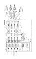
- FIG. 8 is a diagram showing an internal configuration of the satellite transmitter according to the second embodiment of the present invention.
- the basic configuration is the same as that shown in FIG. 1 in the first embodiment. 8 is different from the configuration of FIG. 1 in the first embodiment in the following points. That is, in the first embodiment, the frequency of each transmission beam is exclusive, and one DBF transmission unit 2 is configured for the satellite transmitter.
- each transmission beam is spatially exclusive and a plurality of M DBF transmission units 2a and 2b are provided.
- the number M is set according to the number M of beams to be transmitted. That is, in the second embodiment, M DBF transmitters 2 are provided corresponding to the number M of beams to be transmitted. This difference will be mainly described below.
- Each of the transmission beams 16a to 16d has the following meanings as in the first embodiment.
- Transmit beam 16a Transmit beam to Point 1
- Transmit beam 16b Transmit beam to Point 2
- Transmit beam 16c Transmit beam to Point m
- Transmit beam 16d Transmit beam to Point M
- the receiving point on the ground and the transmitting beam were arbitrary.
- the receiving point on the ground and the transmitting beam are assumed to be exclusive. That is, in the second embodiment, it is assumed that the receiving point on the ground is selected so that sufficient isolation can be ensured for forming the transmission beam.
- the isolation amount to be secured is required from the allowable value of C/I (Carrier-to-interference ratio) in the communication circuit design.
- Each of the DBF transmitters 2a and 2b includes excitation coefficient multiplication units 11a to 11d, an excitation coefficient calculation unit 20, and a storage device 17.
- the relay signal 51 is also individually input to each of the DBF transmitters 2a and 2b for each transmission beam. That is, the relay signal 51a is input to the DBF transmission unit 2a, and the relay signal 51b is input to the DBF transmission unit 2b.
- other beams other than the relay signals 51a and 51b have the same configuration.
- the processing after the multiplexing units 12a to 12d and the processing by the feedback configuration using the PAPR calculation unit 18 and the inter-beam relative phase calculation unit 19 are all the same as the configuration of FIG.
- -The number of points from which the satellite transmitter 1 simultaneously transmits communication signals is set to 1 to M.
- -The number of elements 15a to 15d of the transmitting antenna is set to K from 1 to K.
- the center frequency of the beam transmitted to the point m is fm, and the band is ⁇ fm.
- -Points 1 to M that receive the communication signal output from the satellite transmitter 1 are points on the ground that are covered by the radiation pattern of the M transmission beams 16a to 16d.
- the points 1 to M, which are receiving points on the ground, and the transmission beams 16a to 16d are arbitrary in the first embodiment, but are assumed to be exclusive in the second embodiment.
- FIG. 9 is a schematic diagram of relay signals 51a and 51b input to the satellite transmitter 1 according to the second embodiment of the present invention.
- Each of the relay signals 51a and 51b is a digital signal, and is a signal obtained by demultiplexing the signal in the total band ⁇ f with the resolution in the band ⁇ fch.
- the band ⁇ fch having the minimum resolution is called a sub-channel.
- Each subchannel has digital values of amplitude and phase.
- the number of sub-channels is N channels.
- one relay signal 51 includes all the transmission beams 16a to 16d.
- the transmission beams 16a to 16d are input to different DBF transmission units 2a and 2b as relay signals 51a and 51b different for each beam.
- the DBF transmitter 2a receives the transmission beam included in the relay signal 51a
- the DBF transmitter 2b receives the transmission beam included in the relay signal 51b.
- the transmission beams included in one relay signal 51 do not share the same sub-channel.
- the frequencies may be shared between the beams. That is, as shown in FIG. 9, the relay signal 51a and the relay signal 51b may use the same frequency.
- Each of the relay signal 51a input to the DBF transmission unit 2a and the relay signal 51b input to the DBF transmission unit 2b is multiplied by the excitation coefficient corresponding to the beam. That is, in the DBF transmitter 2a, the excitation coefficient corresponding to the beam 1 is read from the storage device 17. The read excitation coefficient is subjected to multiplication processing by the excitation coefficient multiplication units 11a to 11d after being given an inter-beam relative phase by the excitation coefficient calculation unit 20.
- the excitation coefficient corresponding to the beam 2 is read from the storage device 17.
- the read excitation coefficient is subjected to multiplication processing by the excitation coefficient multiplication units 11a to 11d after being given an inter-beam relative phase by the excitation coefficient calculation unit 20. The same process is performed in the remaining M ⁇ 2 DBF transmission units.
- the relay signals output from the M DBF transmitters 2 are input to the multiplexers 12a to 12d provided corresponding to the respective transmit antenna elements 15a to 15d.
- the number of inputs to each of the multiplexing units 2a to 2d is one.
- M relay signals corresponding to the number of beams are input to each of the multiplexing units 2a to 2d.
- the multiplexing units 12a to 12d have a function of adding the relay signals of all the beams for all the sub-channels, and after the addition, all the sub-channels on the frequency axis are combined and converted into a real-time digital signal. .. That is, the multiplexing units 12a to 12d convert the spectrum data with the resolution of the band ⁇ fch into a real-time digital signal by the IFFT.
- the operations of the DACs 13a to 13d, the amplifiers 14a to 14d, the transmitting antenna elements 15a to 15d, and the PAPR calculating unit 18, which are the multiplexing units 12a to 12d and later, are the same as those in the first embodiment. Further, regarding the inter-beam relative phase calculation unit 19, in the first embodiment, the calculated inter-beam relative phase is given to the single DBF transmission unit 2. On the other hand, the inter-beam relative phase calculation unit 19 according to the second embodiment provides the same inter-beam relative phase to the excitation coefficient calculation unit 20 in each DBF transmission unit 2a, 2b.
- the relay signal 51 is input from the satellite receiver 31.
- DBF receivers 32 are provided for the number of receive beams in the configuration of the satellite receiver 31 shown in FIG.
- the reception beam can be spatially exclusive like the transmission beam.
- the satellite transmitter according to the second embodiment and the relay satellite communication system including the satellite transmitter have the following effects when compared with the related art.
- (Effect 1) The dynamic range can be secured by suppressing the PAPR even when a satellite-mounted DAC having a small number of resolution bits is used.
- (Effect 2) By reducing the backoff margin of the amplifier by suppressing the PAPR, it is possible to suppress the peak power and increase the transmission power.
- (Effect 3) Each beam is spatially separated. Therefore, the relative phases between the beams do not affect each other in demodulation, and it is not necessary for the terrestrial receiving station to share the phase provided between the clusters in the satellite repeater.
- (Effect 4) The relay signal may use the same frequency between the beams, and the frequency utilization efficiency is improved.
- (Effect 5) Real-time traffic fluctuations can be tracked by the relative phase control between beams by the feedback configuration.
- Embodiment 3 ⁇ Structure>
- the PAPR calculation process and the feedback control process for updating the excitation coefficient based on the PAPR calculation result are performed inside the satellite transmitter 1 of the satellite repeater 200.
- the third embodiment a case will be described in which the PAPR calculation process and the feedback control process for updating the excitation coefficient are performed on the ground side.
- the element having the maximum PAPR is Calculation can be performed on the ground side. Therefore, in this case, a PAPR calculation unit and an inter-beam relative phase calculation unit are provided on the ground side, and the inter-beam relative phase ⁇ m is given from the ground to the satellite repeater 200 by a command. be able to.
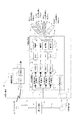
- FIG. 10 is a diagram showing a configuration example of a relay satellite communication system including a satellite relay 200 according to the third embodiment of the present invention.
- the satellite transmitter 1 included in the satellite repeater 200 according to the third embodiment shown in FIG. 10 has a transmission beam as a communication signal for one or more points m, as in the first embodiment.
- the purpose is to simultaneously transmit 16a to 16d.
- Each of the transmission beams 16a to 16d also means the following, as in the first embodiment.
- Transmit beam 16a Transmit beam to Point 1
- Transmit beam 16b Transmit beam to Point 2
- Transmit beam 16c Transmit beam to Point m
- Transmit beam 16d Transmit beam to Point M
- points 1 to M which receive the communication signal output from the satellite transmitter 1, are set as arbitrary points on the ground that are covered by the radiation pattern of the M transmission beams 16a to 16d.
- the transmission beams 16a to 16d are assumed to have no frequency overlap. That is, it is assumed that the frequencies of the transmission beams 16a to 16d in the third embodiment are mutually exclusive, as in the first embodiment.
- the PAPR calculation unit 18 and the inter-beam relative phase calculation unit 19 for suppressing the PAPR are provided in the satellite transmitter 1.
- the PAPR calculator 18 and the inter-beam relative phase calculator 19 are not provided in the satellite transmitter 1. Instead, the ground communication control station 57 calculates the phase for reducing the PAPR, and the set value of the excitation coefficient to be updated is sent as a command to the satellite repeater 200 through the ground satellite control station 54.
- the operation of the satellite repeater 200 is the same as that of the first embodiment except that the PAPR calculating unit 18 and the inter-beam relative phase calculating unit 19 are not present, and therefore the description thereof is omitted.
- FIG. 11 is a schematic diagram of the communication control station 57 according to the third embodiment of the present invention.
- the communication control station 57 shown in FIG. 11 includes a relay signal generation unit 72, an element selection unit 73, a multiplexing unit 74, a PAPR calculation unit 75, an inter-beam relative phase calculation unit 76, an excitation coefficient calculation unit 77, and a transmission beam control. It is configured to include a portion 78.
- a signal for relaying from the ground communication network 71 to another ground station via the satellite relay 200 is input to the communication control station 57 from the ground communication network 71.
- the relay signal generation unit 72 in the communication control station 57 generates a relay signal as shown in FIG. 2 as the relay signal 58 based on this signal input from the ground communication network 71.
- the relay signal 58 is transmitted to the satellite relay 200 as the relay signal 53 through the ground gateway station 52.
- the element selection unit 73 inputs a part of the relay signal 58 generated by the relay signal generation unit 72.
- the element selection unit 73 multiplies the beam forming excitation coefficient provided from the transmission beam control unit 78 by the relay signal 58 to obtain a signal similar to the element signal generated by the DBF transmission unit 2 on the satellite repeater 200. Is simulated.
- the element selection unit 73 selects the element with the highest power from the simulated element signals, and outputs the relay signal after the excitation coefficient multiplication of the selected element to the multiplexing unit 74.
- the multiplexing unit 74 has a function of multiplexing the relay signal of the element having the largest average power on the frequency axis and converting it into a real-time digital signal. That is, the multiplexing unit 74 converts the spectrum data having the resolution of the band ⁇ fch into a real-time digital signal by performing a fast inverse Fourier transform.
- the real-time digital signal output from the multiplexer 74 is input to the PAPR calculator 75.
- the PAPR calculation unit 75 calculates the PAPR by measuring the average power and the peak power at each specific time.
- the PAPR information calculated by the PAPR calculation unit 75 is input to the inter-beam relative phase calculation unit 76.
- the inter-beam relative phase calculation unit 76 selects one inter-beam relative phase ⁇ m based on the PAPR information.
- the processing by the inter-beam relative phase calculation unit 76 is the same as the processing in step 120 of FIG.
- Information on the inter-beam relative phase ⁇ m is sent from the inter-beam relative phase calculation unit 76 to the excitation coefficient calculation unit 77 and the transmission beam control unit 78.
- the transmission beam control unit 78 adds the inter-beam relative phase ⁇ m sent from the inter-beam relative phase calculation unit 76 and the excitation coefficient phase for beam forming, and then generates a new excitation coefficient.
- the transmission beam controller 78 gives the generated new excitation coefficient to the element selector 73. As a result, a similar series of processes is repeated using the updated excitation coefficient.
- the excitation coefficient calculator 77 calculates the excitation coefficient A k after adding the phase of the beam forming excitation coefficient and the inter-beam relative phase ⁇ m, and transmits it to the ground satellite control station 54 as the excitation coefficient 59.
- the excitation coefficient 59 sent as the command signal 55 from the terrestrial satellite control station 54 is set in the excitation coefficient multiplication units 11a to 11d in the DBF transmission unit 2 through the storage device 17.
- the communication control station 57 side calculates in advance the relative phase between beams that reduces the PAPR of the transmission antenna elements 15a to 15d of the satellite transmitter 1, and also combines the excitation coefficient A k with the excitation coefficient for beam forming.
- the configuration inside the satellite repeater 200 can be simplified.
- the relay satellite communication system has the following effects when compared with the related art.
- (Effect 1) The dynamic range can be secured by suppressing the PAPR even when a satellite-mounted DAC having a small number of resolution bits is used.
- (Effect 2) By reducing the backoff margin of the amplifier by suppressing the PAPR, it is possible to suppress the peak power and increase the transmission power.
- (Effect 3) The configuration of the satellite repeater can be simplified by calculating the PAPR reduction phase on the ground station side.
- Effect 4 Real-time traffic fluctuations can be tracked by the relative phase control between beams by the feedback configuration.
- the inter-beam relative phase ⁇ m is a parameter given for each transmission beam.
- the inter-beam relative phase ⁇ m is a parameter that can control the inter-beam relative phase without affecting the transmission beam formation itself.
- the satellite transmitter and the relay satellite communication system calculate the inter-beam relative phase that suppresses the peak power of the transmitting antenna element based on the PAPR calculation result, and use the calculated inter-beam relative phase for excitation. It has a configuration for updating the coefficient. As a result, it is possible to realize the satellite transmitter and the relay satellite communication system in which the limitation of the transmission power is suppressed and it is not necessary to share the phase control information between the transmitter side and the receiver side.
- excitation coefficient update processing is performed by either the satellite transmitter side as described in the first and second embodiments or the ground side as described in the third embodiment. It is feasible.
Landscapes
- Engineering & Computer Science (AREA)
- Computer Networks & Wireless Communication (AREA)
- Signal Processing (AREA)
- Physics & Mathematics (AREA)
- Astronomy & Astrophysics (AREA)
- Aviation & Aerospace Engineering (AREA)
- General Physics & Mathematics (AREA)
- Radio Relay Systems (AREA)
Abstract
L'invention concerne un émetteur satellite comprenant : K éléments d'antenne de transmission; une unité de multiplexage pour multiplexer chacun des K signaux numériques sur un axe de fréquence et ensuite convertir le résultat en un signal numérique dans un domaine temporel; un convertisseur numérique-analogique; une unité de calcul de PAPR pour calculer un PAPR concernant chacun des K signaux numériques; une unité de calcul de phase relative inter-faisceaux pour calculer une phase relative inter-faisceaux qui supprime la puissance de crête des éléments d'antenne de transmission, sur la base de K PAPR; une unité de calcul des coefficients d'excitation pour calculer K coefficients d'excitation après mise à jour sur la base de la phase relative inter-faisceaux et un coefficient d'excitation pour la formation de faisceaux; et une unité de multiplication des coefficients d'excitation pour multiplier chacun des K coefficients d'excitation après mise à jour par un signal relais reçu dans un domaine de fréquence et ainsi générer un signal numérique dans un domaine de fréquence pour être délivré à l'unité de multiplexage.
Priority Applications (3)
| Application Number | Priority Date | Filing Date | Title |
|---|---|---|---|
| US17/425,322 US11764868B2 (en) | 2019-01-31 | 2019-09-20 | Satellite transmitter and relay satellite communication system |
| JP2020569359A JP7098002B2 (ja) | 2019-01-31 | 2019-09-20 | 衛星送信機および中継衛星通信システム |
| EP19912839.8A EP3920428B1 (fr) | 2019-01-31 | 2019-09-20 | Émetteur satellite et système de communication par satellite relais |
Applications Claiming Priority (2)
| Application Number | Priority Date | Filing Date | Title |
|---|---|---|---|
| JP2019-015450 | 2019-01-31 | ||
| JP2019015450 | 2019-01-31 |
Publications (1)
| Publication Number | Publication Date |
|---|---|
| WO2020158040A1 true WO2020158040A1 (fr) | 2020-08-06 |
Family
ID=71840038
Family Applications (1)
| Application Number | Title | Priority Date | Filing Date |
|---|---|---|---|
| PCT/JP2019/036951 Ceased WO2020158040A1 (fr) | 2019-01-31 | 2019-09-20 | Émetteur satellite et système de communication par satellite relais |
Country Status (4)
| Country | Link |
|---|---|
| US (1) | US11764868B2 (fr) |
| EP (1) | EP3920428B1 (fr) |
| JP (1) | JP7098002B2 (fr) |
| WO (1) | WO2020158040A1 (fr) |
Cited By (7)
| Publication number | Priority date | Publication date | Assignee | Title |
|---|---|---|---|---|
| JP2022107198A (ja) * | 2021-01-08 | 2022-07-21 | 三菱電機株式会社 | リソース決定装置、リソース決定方法及びリソース決定プログラム |
| CN115643145A (zh) * | 2022-09-02 | 2023-01-24 | 北京遥感设备研究所 | 一种ofdm系统中联合pts-cf峰均比抑制方法 |
| JP2023100142A (ja) * | 2022-01-05 | 2023-07-18 | 三菱電機株式会社 | 衛星通信システム及び衛星通信管理方法 |
| JPWO2023145012A1 (fr) * | 2022-01-28 | 2023-08-03 | ||
| JP2023110570A (ja) * | 2022-01-28 | 2023-08-09 | 三菱電機株式会社 | 衛星通信システム、中継器制御局、衛星中継器および送信電力決定方法 |
| JP2023122242A (ja) * | 2022-02-22 | 2023-09-01 | 株式会社東芝 | 移動局装置、制御方法、および衛星通信システム |
| CN118539972A (zh) * | 2024-07-26 | 2024-08-23 | 上海金卓科技有限公司 | 一种卫星信号转发装置、芯片及方法 |
Families Citing this family (1)
| Publication number | Priority date | Publication date | Assignee | Title |
|---|---|---|---|---|
| EP4236221A4 (fr) * | 2020-11-30 | 2023-12-27 | Huawei Technologies Co., Ltd. | Appareil et procédé de suppression à rapport crête-moyenne adaptatif (papr), et dispositif de communication |
Citations (3)
| Publication number | Priority date | Publication date | Assignee | Title |
|---|---|---|---|---|
| JP2008017415A (ja) * | 2006-07-10 | 2008-01-24 | Mitsubishi Electric Corp | 無線通信システム |
| JP2014123897A (ja) * | 2012-12-21 | 2014-07-03 | Mitsubishi Electric Corp | 衛星搭載中継器、受信装置および衛星通信システム |
| WO2017150624A1 (fr) * | 2016-03-02 | 2017-09-08 | 三菱電機株式会社 | Système de communication par satellite à faisceaux multiples, dispositif relais et dispositif de commande |
Family Cites Families (10)
| Publication number | Priority date | Publication date | Assignee | Title |
|---|---|---|---|---|
| JP5339450B2 (ja) | 2009-12-21 | 2013-11-13 | Nec東芝スペースシステム株式会社 | 無線通信装置および無線通信方法 |
| KR102065696B1 (ko) * | 2013-08-01 | 2020-01-14 | 삼성전자주식회사 | 무선 통신 시스템에서 적응적 송신 전력 정규화를 위한 장치 및 방법 |
| EP2884675A1 (fr) | 2013-12-12 | 2015-06-17 | Airbus Defence and Space Limited | Compensation de phase ou d'amplitude en forme de faisceau |
| US10348394B1 (en) * | 2014-03-14 | 2019-07-09 | Tarana Wireless, Inc. | System architecture and method for enhancing wireless networks with mini-satellites and pseudollites and adaptive antenna processing |
| CA3009761C (fr) | 2015-12-29 | 2024-06-11 | Blue Danube Systems, Inc. | Reduction de facteur de crete multi-faisceau |
| WO2018063855A1 (fr) * | 2016-09-28 | 2018-04-05 | Idac Holdings, Inc. | Transmission sans signal de référence servant à des systèmes sans fil |
| CN118117305A (zh) * | 2016-12-21 | 2024-05-31 | 英特尔公司 | 无线通信技术、装置和方法 |
| WO2020150700A1 (fr) * | 2019-01-18 | 2020-07-23 | Apple Inc. | Compression d'informations d'état de canal (csi) dans le domaine fréquentiel |
| US10985951B2 (en) * | 2019-03-15 | 2021-04-20 | The Research Foundation for the State University | Integrating Volterra series model and deep neural networks to equalize nonlinear power amplifiers |
| US11715876B2 (en) * | 2019-07-15 | 2023-08-01 | Wafer Llc | System and method for real-time multiplexing phased array antennas to modems |
-
2019
- 2019-09-20 WO PCT/JP2019/036951 patent/WO2020158040A1/fr not_active Ceased
- 2019-09-20 EP EP19912839.8A patent/EP3920428B1/fr active Active
- 2019-09-20 US US17/425,322 patent/US11764868B2/en active Active
- 2019-09-20 JP JP2020569359A patent/JP7098002B2/ja active Active
Patent Citations (3)
| Publication number | Priority date | Publication date | Assignee | Title |
|---|---|---|---|---|
| JP2008017415A (ja) * | 2006-07-10 | 2008-01-24 | Mitsubishi Electric Corp | 無線通信システム |
| JP2014123897A (ja) * | 2012-12-21 | 2014-07-03 | Mitsubishi Electric Corp | 衛星搭載中継器、受信装置および衛星通信システム |
| WO2017150624A1 (fr) * | 2016-03-02 | 2017-09-08 | 三菱電機株式会社 | Système de communication par satellite à faisceaux multiples, dispositif relais et dispositif de commande |
Non-Patent Citations (3)
| Title |
|---|
| FUJIMURA, AKINORI, TAIRA AKINORI; ISHIZU FUMIO: "A Study of Flexible Wideband Digital Satellite Transponders", PROCEEDINGS OF THE 2013 IEICE GENERAL CONFERENCE, 5 March 2013 (2013-03-05), pages 334, XP009521989 * |
| L. J. CIMININ. R. SOLLENBERGER: "Peak-to-Average power ratio reduction of an OFDM signal using partial transmit sequences", IEEE COMMUN. LETT, vol. 4, no. 3, March 2000 (2000-03-01), pages 86 - 88 |
| MENGALI, ALBERTO, MYSORE R BHAVANI SHANKAR; OTTERSTEN BJORN: "Joint predistortion and PAPR reduction in multibeam satellite systems", 2016 IEEE INTERNATIONAL CONFERENCE ON COMMUNICATIONS (ICC, 27 May 2016 (2016-05-27), pages 1 - 7, XP032922119, DOI: 10.1109/ICC.2016.7510944 * |
Cited By (12)
| Publication number | Priority date | Publication date | Assignee | Title |
|---|---|---|---|---|
| JP2022107198A (ja) * | 2021-01-08 | 2022-07-21 | 三菱電機株式会社 | リソース決定装置、リソース決定方法及びリソース決定プログラム |
| JP7450560B2 (ja) | 2021-01-08 | 2024-03-15 | 三菱電機株式会社 | リソース決定装置、リソース決定方法及びリソース決定プログラム |
| JP2023100142A (ja) * | 2022-01-05 | 2023-07-18 | 三菱電機株式会社 | 衛星通信システム及び衛星通信管理方法 |
| JP7660528B2 (ja) | 2022-01-05 | 2025-04-11 | 三菱電機株式会社 | 衛星通信システム及び衛星通信管理方法 |
| JPWO2023145012A1 (fr) * | 2022-01-28 | 2023-08-03 | ||
| WO2023145012A1 (fr) | 2022-01-28 | 2023-08-03 | 三菱電機株式会社 | Dispositif de commande de répéteur, système de communication sans fil, circuit de commande, support de stockage et procédé de détermination de valeur de commande |
| JP2023110570A (ja) * | 2022-01-28 | 2023-08-09 | 三菱電機株式会社 | 衛星通信システム、中継器制御局、衛星中継器および送信電力決定方法 |
| JP7504313B2 (ja) | 2022-01-28 | 2024-06-21 | 三菱電機株式会社 | 中継器制御装置、無線通信システム、制御回路、記憶媒体、および、制御値決定方法 |
| JP7657164B2 (ja) | 2022-01-28 | 2025-04-04 | 三菱電機株式会社 | 衛星通信システム、中継器制御局、衛星中継器および送信電力決定方法 |
| JP2023122242A (ja) * | 2022-02-22 | 2023-09-01 | 株式会社東芝 | 移動局装置、制御方法、および衛星通信システム |
| CN115643145A (zh) * | 2022-09-02 | 2023-01-24 | 北京遥感设备研究所 | 一种ofdm系统中联合pts-cf峰均比抑制方法 |
| CN118539972A (zh) * | 2024-07-26 | 2024-08-23 | 上海金卓科技有限公司 | 一种卫星信号转发装置、芯片及方法 |
Also Published As
| Publication number | Publication date |
|---|---|
| US11764868B2 (en) | 2023-09-19 |
| EP3920428A4 (fr) | 2022-04-13 |
| JPWO2020158040A1 (ja) | 2021-10-07 |
| US20220085875A1 (en) | 2022-03-17 |
| JP7098002B2 (ja) | 2022-07-08 |
| EP3920428A1 (fr) | 2021-12-08 |
| EP3920428B1 (fr) | 2024-10-30 |
Similar Documents
| Publication | Publication Date | Title |
|---|---|---|
| JP7098002B2 (ja) | 衛星送信機および中継衛星通信システム | |
| JP3718337B2 (ja) | 適応可変指向性アンテナ | |
| JP3576099B2 (ja) | スマートアンテナを用いた受信装置、スマートアンテナを用いた受信方法及びビーム形成回路 | |
| US8054742B2 (en) | System and method for sidelobe suppression in communications systems | |
| KR100491194B1 (ko) | 다중 캐리어 통신 시스템에서 피크 전력 감소를 위한시스템 및 방법 | |
| US20050018597A1 (en) | Radio base station apparatus | |
| JP4871813B2 (ja) | 無線通信装置、無線通信方法及びピーク抑圧方法 | |
| JP4401055B2 (ja) | 偏差補償装置 | |
| JP2009055558A (ja) | 直交多重信号のピーク抑圧方法、ピーク抑圧回路、及び送信装置 | |
| JPWO2001031745A1 (ja) | 偏差補償装置 | |
| US20190173709A1 (en) | Apparatus and method for reducing signal distortion | |
| JP5208980B2 (ja) | 無線通信システム、無線通信システムにおける送信装置および送信方法 | |
| JP2005348236A (ja) | アレーアンテナ送信装置及び受信装置並びにキャリブレーション方法 | |
| US20190190595A1 (en) | System and method for efficient wideband code division multiplexing in subband domain | |
| JP5536614B2 (ja) | 通信装置及び通信方法 | |
| JP6536159B2 (ja) | 無線通信装置およびウェイト行列の決定方法 | |
| JP4253445B2 (ja) | 偏差補償装置 | |
| JP5901868B1 (ja) | 無線送信装置 | |
| JP4426398B2 (ja) | アレイアンテナ受信装置 | |
| JP2007020072A (ja) | 無線通信システム、無線通信装置及び無線通信方法 | |
| JP2006295681A (ja) | 無線通信装置 | |
| CN101326843B (zh) | 使用天线阵列产生全向发射的通信设备和方法 | |
| JP2024108041A (ja) | 無線送信装置および無線送信方法 | |
| JP2007243546A (ja) | アンテナ校正装置およびアンテナ校正方法 | |
| JP6396258B2 (ja) | 無線通信システムの送信装置および無線通信システムの送信方法 |
Legal Events
| Date | Code | Title | Description |
|---|---|---|---|
| 121 | Ep: the epo has been informed by wipo that ep was designated in this application |
Ref document number: 19912839 Country of ref document: EP Kind code of ref document: A1 |
|
| ENP | Entry into the national phase |
Ref document number: 2020569359 Country of ref document: JP Kind code of ref document: A |
|
| NENP | Non-entry into the national phase |
Ref country code: DE |
|
| ENP | Entry into the national phase |
Ref document number: 2019912839 Country of ref document: EP Effective date: 20210831 |