WO2020158551A1 - 有機性汚泥の処理設備および処理方法 - Google Patents
有機性汚泥の処理設備および処理方法 Download PDFInfo
- Publication number
- WO2020158551A1 WO2020158551A1 PCT/JP2020/002210 JP2020002210W WO2020158551A1 WO 2020158551 A1 WO2020158551 A1 WO 2020158551A1 JP 2020002210 W JP2020002210 W JP 2020002210W WO 2020158551 A1 WO2020158551 A1 WO 2020158551A1
- Authority
- WO
- WIPO (PCT)
- Prior art keywords
- organic sludge
- hot water
- concentrated
- sludge
- filtration screen
- Prior art date
- Legal status (The legal status is an assumption and is not a legal conclusion. Google has not performed a legal analysis and makes no representation as to the accuracy of the status listed.)
- Ceased
Links
Images

Classifications
-
- B—PERFORMING OPERATIONS; TRANSPORTING
- B01—PHYSICAL OR CHEMICAL PROCESSES OR APPARATUS IN GENERAL
- B01D—SEPARATION
- B01D29/00—Filters with filtering elements stationary during filtration, e.g. pressure or suction filters, not covered by groups B01D24/00 - B01D27/00; Filtering elements therefor
- B01D29/50—Filters with filtering elements stationary during filtration, e.g. pressure or suction filters, not covered by groups B01D24/00 - B01D27/00; Filtering elements therefor with multiple filtering elements, characterised by their mutual disposition
- B01D29/52—Filters with filtering elements stationary during filtration, e.g. pressure or suction filters, not covered by groups B01D24/00 - B01D27/00; Filtering elements therefor with multiple filtering elements, characterised by their mutual disposition in parallel connection
- B01D29/54—Filters with filtering elements stationary during filtration, e.g. pressure or suction filters, not covered by groups B01D24/00 - B01D27/00; Filtering elements therefor with multiple filtering elements, characterised by their mutual disposition in parallel connection arranged concentrically or coaxially
-
- B—PERFORMING OPERATIONS; TRANSPORTING
- B01—PHYSICAL OR CHEMICAL PROCESSES OR APPARATUS IN GENERAL
- B01D—SEPARATION
- B01D29/00—Filters with filtering elements stationary during filtration, e.g. pressure or suction filters, not covered by groups B01D24/00 - B01D27/00; Filtering elements therefor
- B01D29/11—Filters with filtering elements stationary during filtration, e.g. pressure or suction filters, not covered by groups B01D24/00 - B01D27/00; Filtering elements therefor with bag, cage, hose, tube, sleeve or like filtering elements
- B01D29/114—Filters with filtering elements stationary during filtration, e.g. pressure or suction filters, not covered by groups B01D24/00 - B01D27/00; Filtering elements therefor with bag, cage, hose, tube, sleeve or like filtering elements arranged for inward flow filtration
-
- B—PERFORMING OPERATIONS; TRANSPORTING
- B01—PHYSICAL OR CHEMICAL PROCESSES OR APPARATUS IN GENERAL
- B01D—SEPARATION
- B01D29/00—Filters with filtering elements stationary during filtration, e.g. pressure or suction filters, not covered by groups B01D24/00 - B01D27/00; Filtering elements therefor
- B01D29/11—Filters with filtering elements stationary during filtration, e.g. pressure or suction filters, not covered by groups B01D24/00 - B01D27/00; Filtering elements therefor with bag, cage, hose, tube, sleeve or like filtering elements
- B01D29/117—Filters with filtering elements stationary during filtration, e.g. pressure or suction filters, not covered by groups B01D24/00 - B01D27/00; Filtering elements therefor with bag, cage, hose, tube, sleeve or like filtering elements arranged for outward flow filtration
-
- B—PERFORMING OPERATIONS; TRANSPORTING
- B01—PHYSICAL OR CHEMICAL PROCESSES OR APPARATUS IN GENERAL
- B01D—SEPARATION
- B01D29/00—Filters with filtering elements stationary during filtration, e.g. pressure or suction filters, not covered by groups B01D24/00 - B01D27/00; Filtering elements therefor
- B01D29/62—Regenerating the filter material in the filter
- B01D29/64—Regenerating the filter material in the filter by scrapers, brushes, nozzles, or the like, acting on the cake side of the filtering element
- B01D29/6469—Regenerating the filter material in the filter by scrapers, brushes, nozzles, or the like, acting on the cake side of the filtering element scrapers
- B01D29/6476—Regenerating the filter material in the filter by scrapers, brushes, nozzles, or the like, acting on the cake side of the filtering element scrapers with a rotary movement with respect to the filtering element
-
- C—CHEMISTRY; METALLURGY
- C02—TREATMENT OF WATER, WASTE WATER, SEWAGE, OR SLUDGE
- C02F—TREATMENT OF WATER, WASTE WATER, SEWAGE, OR SLUDGE
- C02F11/00—Treatment of sludge; Devices therefor
- C02F11/12—Treatment of sludge; Devices therefor by de-watering, drying or thickening
- C02F11/121—Treatment of sludge; Devices therefor by de-watering, drying or thickening by mechanical de-watering
- C02F11/125—Treatment of sludge; Devices therefor by de-watering, drying or thickening by mechanical de-watering using screw filters
-
- C—CHEMISTRY; METALLURGY
- C02—TREATMENT OF WATER, WASTE WATER, SEWAGE, OR SLUDGE
- C02F—TREATMENT OF WATER, WASTE WATER, SEWAGE, OR SLUDGE
- C02F11/00—Treatment of sludge; Devices therefor
- C02F11/18—Treatment of sludge; Devices therefor by thermal conditioning
-
- C—CHEMISTRY; METALLURGY
- C02—TREATMENT OF WATER, WASTE WATER, SEWAGE, OR SLUDGE
- C02F—TREATMENT OF WATER, WASTE WATER, SEWAGE, OR SLUDGE
- C02F11/00—Treatment of sludge; Devices therefor
- C02F11/12—Treatment of sludge; Devices therefor by de-watering, drying or thickening
- C02F11/14—Treatment of sludge; Devices therefor by de-watering, drying or thickening with addition of chemical agents
-
- C—CHEMISTRY; METALLURGY
- C02—TREATMENT OF WATER, WASTE WATER, SEWAGE, OR SLUDGE
- C02F—TREATMENT OF WATER, WASTE WATER, SEWAGE, OR SLUDGE
- C02F2209/00—Controlling or monitoring parameters in water treatment
- C02F2209/09—Viscosity
Definitions
- the present invention for example, an organic sludge treatment facility provided with a dehydrating means for dehydrating an organic sludge such as sewage sludge generated from a sewage treatment plant, and an organic sludge for dehydrating such an organic sludge by a dehydrating means.
- a dehydrating means for dehydrating an organic sludge such as sewage sludge generated from a sewage treatment plant
- an organic sludge for dehydrating such an organic sludge by a dehydrating means.
- an outer cylinder screen having small holes formed in a peripheral wall, and a screw shaft provided inside the outer cylinder screen are disclosed. And a screw blade spirally provided around the screw shaft, and by rotating the screw blade and the screw shaft, the object to be dehydrated put in the outer cylinder screen is conveyed in the axial direction of the screw shaft. While being compressed, the dehydration device discharges the water separated from the object to be dehydrated from the small holes of the outer cylinder screen, wherein the outer cylinder screen has a heating surface to be heated and a filtration surface to which the small holes are exposed. The device is described.
- a heating jacket having a structure for circulating a heat medium inside is attached to a part of the outer cylinder screen, and the heating jacket is attached to the outside.
- a portion of the cylindrical screen serves as a heating surface, and the heating surface and the filtering surface are alternately and repeatedly arranged in the axial direction of the screw shaft.
- the water content of the dehydrated sludge is reduced by dehydrating the object to be dehydrated transported in the outer cylinder screen while heating it on the heating surface of the outer cylinder screen.
- the portion of the outer cylinder screen to which the heating jacket is attached as described above is used as a heating surface, and this heating surface has a dehydration target such as a filtration surface. No small pores separate from the object are formed. Therefore, if the area of the heating surface is increased in order to further reduce the water content of the dehydrated sludge, the area of the filtration surface will decrease and the water separated from the object to be dehydrated can be efficiently discharged. On the contrary, if the area of the filtration surface in which the small holes are formed is increased, the area of the heating surface is reduced and it becomes impossible to reduce the water content of the dehydrated sludge.
- the present invention has been made under such a background, and a dehydrating means capable of achieving both a low water content by heating an organic sludge and an efficient discharge of water separated from the organic sludge.
- An object of the present invention is to provide a treatment facility and a treatment method for organic sludge including the above.
- the organic sludge treatment equipment of the present invention is an organic sludge treatment equipment provided with a dehydrating means for dehydrating the organic sludge, and in the dehydrating means, a filtration screen for filtering the organic sludge in a casing.
- a dehydrating means for dehydrating the organic sludge
- a filtration screen for filtering the organic sludge in a casing.
- the first space is supplied with the organic sludge
- the second space is supplied with dewatered hot water from the dewatering hot water supply means 50.
- Dehydrated hot water having a temperature of not less than 100°C and less than 100°C is supplied.
- the method for treating organic sludge of the present invention is a method for treating organic sludge by dehydrating the organic sludge by a dehydrating means, and in the dehydrating means, a filter screen for filtering the organic sludge in a casing.
- the organic sludge is supplied to the first space, and the second space is heated to 50° C. from the dehydrated hot water supply means.
- Dehydrated warm water having a temperature in the range of 100° C. or higher is supplied.
- the dehydration means in the dehydration means, the first space among the plurality of spaces divided by the filter screen arranged in the casing for filtering the organic sludge is used. Since the organic sludge is supplied to the second space, the dehydrated hot water having a temperature in the range of 50° C. to less than 100° C. is supplied to the second space from the dehydrated hot water supply means. Is heated by the dehydrated hot water supplied to the second space, the viscosity of the organic sludge is reduced, and the water retained in the organic sludge is separated by thermal denaturation of the protein.
- the water thus separated from the organic sludge flows through the filtration screen into the second space and is discharged, so that the water content of the organic sludge can be reduced. Further, since the filtration resistance is reduced due to the decrease in the viscosity of the organic sludge, it is possible to easily discharge the water separated from the organic sludge. Therefore, according to the organic sludge treatment facility and the treating method having the above-described configurations, it is possible to reduce the water content of the dehydrated organic sludge and to efficiently discharge the water separated from the organic sludge.
- the temperature of the dehydrated hot water is less than 50°C, it is not possible to sufficiently obtain the effects due to the decrease in the viscosity of the organic sludge and the separation of water as described above. Further, if the temperature of the dehydrated hot water exceeds 100°C, handling becomes difficult.
- the temperature of the dehydrated hot water is preferably in the range of 60°C or higher and 90°C or lower. The higher the temperature of dewatered hot water, the more the viscosity of organic sludge decreases and the separation of water by heat denaturation of proteins is promoted. However, when the hot water used in the treatment equipment is used as dewatered hot water, the temperature is 60°C or higher. A temperature range of 90°C or lower is realistic.
- the dewatering means has an inner filtration screen which is arranged in the casing in a cylindrical or conical shape with an axis extending in the longitudinal direction as a center, and An outer filtration screen that is cylindrical or conical with the filtration screen and is disposed inside the casing with a space outside the inner filtration screen, and a spiral that twists around the axis.
- a ribbon screw that is housed between the filtration screen and the outer filtration screen and is rotated relative to the inner filtration screen and the outer filtration screen about the axis, and the inner filtration screen and the outer filtration screen; It is desirable that the space between them is the first space, and the space inside the inner filtration screen and the space outside the outer filtration screen are the second spaces.
- a concentrating means for concentrating the coagulated organic sludge by adding a coagulant is provided, and the organic sludge concentrated by the concentrating means is dehydrated by the dewatering means.
- the concentrated warm water at a temperature of 50° C. or more and less than 100° C. is also supplied from the concentrated warm water supplying means to the concentrating means and mixed with the organic sludge, so that the organic sludge is also condensed in the concentrating means. It is possible to heat denature the protein to thermally denature the protein and to separate the retained water, thereby further improving the dehydration efficiency in the subsequent dehydration means.
- the temperature of the concentrated hot water be in the range of 60° C. or higher and 90° C. or lower for the same reason as the dehydrated hot water supplied to the dehydrating means.
- sludge concentration of 8 wt% to sludge concentration It is more desirable to concentrate in the range of 10 wt %.
- the concentrated hot water supplied to the concentrating means it is desirable to circulate and supply the dehydrated hot water discharged from the dehydrating means to the concentrating means.
- the present invention by heating the organic sludge with the dehydrated warm water in the dehydration means, the water content of the dehydrated organic sludge is reduced and the efficient removal of the water separated from the organic sludge is achieved. It is possible to achieve both.
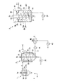
- FIG. 1 It is a schematic diagram showing a 1st embodiment of the treatment equipment of the organic sludge of the present invention.
- 2 is a detailed view of the embodiment shown in FIG. 1.
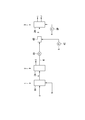
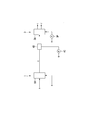
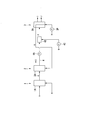
- FIG. 1 It is the schematic which shows 2nd Embodiment of the processing equipment of the organic sludge of this invention. It is the schematic which shows 3rd Embodiment of the processing equipment of the organic sludge of this invention. It is the schematic which shows 4th Embodiment of the treatment equipment of the organic sludge of this invention.
- the organic sludge treatment facility of the present embodiment is a flocculation in which a polymer flocculant B is added to an organic sludge A such as sewage sludge generated from a sewage treatment plant and supplied, such as mixed raw sludge.
- a means 1 a concentrating means 2 for concentrating the agglomerated sludge C whose solid content is agglomerated to some extent by the agglomerating means 1, a dewatering means 3 for dewatering the concentrated sludge D concentrated by the aforesaid concentrating means 2, and these concentrating means 2. It is provided with a concentrated sludge supply path 4 that connects the dehydration means 3.
- the flocculating means 1 is provided with a bottomed cylindrical flocculating tank 1A having a central axis extending in the longitudinal direction in which the organic sludge A and the polymeric flocculant B are supplied and retained from the bottom. ..
- a stirring blade 1b is attached to a rotary shaft 1a along the central axis of the flocculation tank 1A, and a rotary drive means 1c such as a motor provided above the flocculation tank 1A rotates the rotary shaft 1a and the stirring shaft 1a.
- a stirring means 1B for stirring and mixing the organic sludge A and the polymer coagulant B by rotating the blades 1b is provided.
- the aggregating sludge C that is agitated and mixed with the polymer coagulant B by the agitating means 1B and agglomerated is withdrawn from the upper part of the aggregating tank 1A and supplied to the concentrating means 2.
- the concentrating means 2 in the present embodiment is a vertical filtration concentrating machine, and has a bottomed cylindrical shape having a central axis extending in the longitudinal direction similar to the coagulation tank 1A in which the coagulated sludge C supplied from the coagulating means 1 is retained.
- the thickening sludge C is supplied from the upper part of the thickening tank 2A into the thickening tank 2A.
- the body of the concentrating tank 2A serves as a concentrating filtration screen 2a made of wedge wire, punching metal, or the like, and the outer periphery of the concentrating filtration screen 2a is a jacket-shaped filtrate chamber 2b.
- a screw 2d is attached to a rotating shaft 2c along the central axis of the concentrating tank 2A in the concentrating tank 2A, and the rotating shaft 2c and the rotating driving means 2e such as a motor provided on the upper part of the concentrating tank 2A Conveying means 2B for conveying the coagulated sludge C by rotating the screw 2d is provided.
- the coagulated sludge C supplied from the upper part of the thickening tank 2A is transported downward by the transporting means 2B and is concentrated and separated by the concentrating filtration screen 2a so that the sludge concentration is 5 wt% or more, preferably the sludge concentration is 8 wt%.
- the sludge is concentrated in the range of 10 wt%, extracted from the bottom of the concentration tank 2A, and supplied to the concentrated sludge supply path 4 as the concentrated sludge D.
- the bottoms of the concentrating tank 2A and the flocculating tank 1A are formed in a truncated cone shape whose diameter decreases as it goes downward. Further, the water separated from the coagulated sludge C by the concentration/filtration screen 2a is stored in the filtrate chamber 2b and treated as wastewater E.
- the concentrated hot water having a temperature in the range of 50° C. or higher and lower than 100° C., preferably 60° C. or higher and 90° C. or lower is supplied to the concentrating means 2 from a concentrated hot water supplying means (not shown).
- F is supplied by the pump 2C and mixed with the coagulated sludge C supplied from the coagulation means 1.
- the rotating shaft 2c of the conveying means 2B of the concentrating means 2 is made into a hollow cylindrical shape, and a large number (a plurality) of through holes are formed in the cylindrical wall portion of this rotating shaft 2c.
- the concentrated warm water F is supplied from the lower end of the rotating shaft 2c into the rotating shaft 2c and ejected from the through holes, and is supplied from the aggregating means 1 into the concentrating tank 2A and is supplied to the retained sludge C.
- the coagulation sludge C is heated in the concentrating means 2 to thermally denature the protein, the retained water is separated and discharged together with the concentrated warm water F as the wastewater E, and the concentrated sludge D is described above. Is concentrated to a concentration such as.
- a pump 4A for sending the concentrated sludge D to the dehydrating means 3 is provided in the concentrated sludge supply path 4 to which the concentrated sludge D concentrated in this way is supplied, and a high speed is provided between the pump 4A and the dehydrating means 3.
- a mixing means 4B such as a mixer is provided.
- a coagulant G such as an inorganic coagulant such as ferric polysulfate (PFS) or a polymer coagulant is supplied to the mixing means 4B by a pump 4C and added to and mixed with the concentrated sludge D.
- a filter screen 3B for filtering the concentrated sludge D is arranged in the casing 3A, and the filter screen 3B separates the filter screen 3B.
- the concentrated sludge D is supplied to the first space 3A1 among the plurality of spaces in the casing 3A thus prepared.
- the dewatering means 3 in the present embodiment is a vertical screw press, and is disposed in the casing 3A in a cylindrical or conical shape centered on an axis extending in the vertical direction coaxial with the casing 3A.
- the outer filtration screen 3b and the outer filtration screen 3b which are twisted around the axis are housed between the inner filtration screen 3a and the outer filtration screen 3b, and the inner driving filter 3c such as a motor performs inner filtration around the axis. It is provided with a ribbon screw 3d that is rotated relative to the screen 3a and the outer filtration screen 3b.
- a dehydrated hot water supply means (not shown) provides a range of 50°C or higher and lower than 100°C, preferably 60°C or higher.
- Dehydrated hot water H having a temperature in the range of 90° C. or lower is supplied by the pump 3P.
- the inner filtration screen 3a and the outer filtration screen 3b are also formed by a wedge wire, punching metal or the like.
- the casing 3A has a cylindrical shape with a bottom centered on the axis, and the concentrated sludge D is a supply pipe 3f connected to an annular plate-shaped connecting plate 3e connecting the bottoms of the inner filtering screen 3a and the outer filtering screen 3b. Is supplied from the bottom of the casing 3A to the first space 3A1 through the above, and is conveyed upward by the relative rotation of the ribbon screw 3d, while water is separated by the inner filtration screen 3a and the outer filtration screen 3b.
- An annular plate-shaped substrate 3C is arranged in the upper part of the casing 3A, and the outer filtration screen 3b is attached and fixed to the inner peripheral portion of the substrate 3C.
- a lid 3D is provided in the upper opening of the casing 3A above the substrate 3C, the inner filtration screen 3a is attached and fixed to the lid 3D, and the rotation driving means 3c is The ribbon screw 3d is rotated via a cylindrical screw support disposed on the lid 3D and covering the upper portion of the inner filtration screen 3a.
- the inner filtration screen 3a and the outer filtration screen 3b are fixed to the casing in this way, and the ribbon screw 3d is rotated by the rotation driving means 3c.
- the filtration screen 3a and the outer filtration screen 3b may be rotated, and the ribbon screw 3d and the inner filtration screen 3a and the outer filtration screen 3b may be rotated in mutually opposite directions.
- the upper space in the casing 3A between the substrate 3C and the lid 3D is used as the discharge chamber 3E, and the annular upper opening of the first space 3A1 in the discharge chamber 3E is the discharge port 3F.
- the discharge port 3F is provided with a squeeze ring 3G having a frustoconical outer peripheral surface centered on the above-mentioned axis extending toward the outer peripheral side.
- the dehydrated sludge I which has been dehydrated from the concentrated sludge D by separating water while being conveyed upward in the first space 3A1 by the ribbon screw 3d, flows out into the discharge chamber 3E while being compressed by the compression ring 3G from the discharge port 3F. Is discharged.
- the dehydrated hot water H is also supplied from the bottom of the casing 3A to the second space 3A2 in the casing 3A in the present embodiment.
- the dehydrated hot water H thus supplied to the second space 3A2 heats the concentrated sludge D in the first space 3A1, whereby the proteins in the concentrated sludge D are heat-denatured to separate the retained water.
- the water is discharged as drainage J from the drain pipe 3H that is raised from the second space 3A2 together with the dehydrated hot water H that has been filtered by the inner filtration screen 3a and the outer filtration screen 3b and cooled by heating the concentrated sludge D.
- the dehydrating means 3 the first of the plurality of spaces divided by the filter screen 3B arranged in the casing 3A for filtering the concentrated sludge D is provided.
- the concentrated sludge D is supplied to the space 3A1, and the dehydrated hot water H having a temperature in the range of 50° C. or higher and lower than 100° C. is supplied to the second space 3A2 from the dehydrated hot water supply means.
- the viscosity of the concentrated sludge D is reduced and the concentrated sludge is also reduced.
- the water retained in D is separated by heat denaturation of the protein.
- the water thus separated from the concentrated sludge D is filtered through the filter screen 3B, flows into the second space 3A2, and is discharged together with the cooled dewatered warm water H. Therefore, the water is discharged from the discharge port 3F to the discharge chamber 3E. It is possible to reduce the water content of the dehydrated sludge I discharged to the. Further, since the filtration resistance decreases due to the decrease in the viscosity of the concentrated sludge D as described above, it is possible to easily discharge the water separated from the concentrated sludge D to the second space 3A2. Therefore, according to the organic sludge treatment facility and the treatment method having the above-described configurations, it is possible to achieve both the reduction of the water content of the dehydrated sludge I and the efficient discharge of the water separated from the concentrated sludge D.
- the dewatered hot water H and the concentrated hot water F are generated from the flue gas treatment tower drainage of the sludge incineration facility provided in the organic sludge treatment facility, the scrubber drainage of the sludge drying facility, or the digestion gas power generator.
- Hot water can be used. Further, tap water, sand filtered water, or the like can be used after being heated by a boiler.
- the temperature of the dehydrated hot water H is less than 50° C., it is not possible to sufficiently obtain the effects of the above-described decrease in viscosity of the concentrated sludge D and separation of water. Further, if the temperature of the dehydrated hot water H exceeds 100° C., handling becomes difficult. The higher the temperature of the dehydrated hot water H is, the more the viscosity of the concentrated sludge D can be reduced and the water separation can be promoted by the heat denaturation of protein.
- the hot water used in the organic sludge treatment facility is When used as the dehydrated hot water H, a temperature range of 60° C. or higher and 90° C. or lower is practical.
- the dehydrating means 3 has an inner filtration screen 3a arranged in the casing 3A in a cylindrical or conical shape with an axis extending in the longitudinal direction as a center, and the inner filtration screen. 3a and an outer filtration screen 3b which is coaxial with the inner filtration screen 3a and is disposed outside the inner filtration screen 3a in the casing 3A, and an inner filtration which is spirally twisted around the axis.
- a vertical screw press provided with a ribbon screw 3d housed between the screen 3a and the outer filtration screen 3b and rotated about this axis relative to the inner filtration screen 3a and the outer filtration screen 3b. Has been done.
- the space between the inner filtration screen 3a as the filtration screen 3B and the outer filtration screen 3b is the first space 3A1 to which the concentrated sludge D is supplied, and the space inside and outside the inner filtration screen 3a.
- the space outside the filtration screen 3b is the second space 3A2 to which the dehydrated hot water H is supplied.
- the concentrated sludge D supplied to the first space 3A1 between the inner filtration screen 3a and the outer filtration screen 3b is moved in the axial direction by the relative rotation of the ribbon screw 3d. Since it is dehydrated by the inner filtration screen 3a and the outer filtration screen 3b while being transported, it is possible to secure a large filtration area and achieve more efficient filtration. Further, since the concentrated sludge D supplied to the first space 3A1 can be heated by the dehydrated hot water H supplied to the second space 3A2 inside and outside the first space 3A1, heat denaturation of protein The separation of water by can also be promoted more efficiently.
- the concentrated sludge D supplied to the first space 3A1 through the filtration screen can be sufficiently heated, and the water separation due to the thermal denaturation of the protein can be more efficiently performed. Can be promoted. Further, since the filtration surface is always in direct contact with the dehydrated hot water H, the filtration surface does not come into contact with the atmosphere, so that clogging due to drying of the filtration surface can be prevented.
- the vertical screw press having the two filtration screens 3B which are the inner filtration screen 3a and the outer filtration screen 3b, is used as the dewatering means 3, but the axis extending in the longitudinal direction is centered.
- a vertical screw press in which a screw that is helically twisted around this axis and is rotated around the axis is provided in one cylindrical or conical filtration screen, and Patent Document 1
- Patent Document 1 It is also possible to use a horizontal type screw press as described in 1. In addition to these, a rotary press or a multiple plate type screw press can be used.
- a concentrating means 2 for concentrating the coagulated sludge C which is obtained by adding the polymer coagulant B to the organic sludge A in the coagulation means 1, is provided.
- the concentrated sludge D concentrated by the concentration means 2 is dehydrated by the dehydration means 3.
- the concentrated warm water F having a temperature in the range of 50° C. or more and less than 100° C. is supplied to the concentrating means 2 from the concentrated warm water supplying means and mixed with the coagulated sludge C. Therefore, even in the concentrating means 2 in the former stage of the dehydrating means 3, the flocculated sludge C can be heated to thermally denature the protein, and the water retained in the flocculated sludge C can be separated to achieve the dehydration means 3 in the latter stage. It is possible to further improve the dehydration efficiency.
- the aggregation inhibiting substance contained in the liquid of the condensed sludge C can be replaced with the concentrated warm water F, so that the concentrated sludge supply path
- the coagulant G such as polyferric sulfate added in 4 can be prevented from being consumed by the coagulation inhibitor, and the coagulant G can be efficiently reacted with the solid content of the concentrated sludge D.
- the reactivity between the coagulant G and the concentrated sludge D can be improved, and the amount of the coagulant G added can be reduced.
- the dehydration efficiency in the dehydrating means 3 may not be reliably improved, and if it is 100° C. or higher, Handleability is impaired. Further, it is desirable that the temperature of the concentrated hot water F be in the range of 60° C. or higher and 90° C. or lower. Further, in order to further improve the dehydration efficiency in the dehydrating means 3 subsequent to the concentrating means 2, it is desirable that the sludge concentration of the concentrated sludge D concentrated by the concentrating means 2 is concentrated to 5 wt% or more, and the sludge concentration is 8 wt. It is more desirable to concentrate in the range of 10% by weight to 10% by weight.
- the screw 2d is attached to the rotation shaft 2c along the central axis of the concentration tank 2A extending in the vertical direction, and the rotation drive means 2e rotates the rotation shaft 2c and the screw 2d.
- a vertical filtration concentrator provided with a conveying means 2B for conveying the coagulated sludge C by doing so
- any concentrator that does not destroy the coagulated sludge C other than a centrifugal concentrator that destroys the coagulated sludge C may be used.
- a belt-type concentrator, a drum-type concentrator, or a honeycomb-type concentrator can be used.
- the concentrated warm water F is added to and mixed with the coagulated sludge C also in the concentrating means 2 as described above.
- the concentrated warm water F may not be supplied to the concentration means 2. Note that, in FIGS. 3 to 5, the same reference numerals are given to portions common to the schematic diagram shown in FIG.
- the organic sludge A having a sludge concentration of 2 wt% and 25° C. is supplied to the coagulation means 1 at 10 m 3 /h and the coagulated coagulated sludge C is supplied to the concentration means 2.
- the waste water (separated liquid) E of 7.5 m 3 /h at 25° C. is separated, and the concentrated sludge D at 25° C. is supplied to the dehydrating means 3 at a sludge concentration of 8 wt% and 25 m 3. was case, by discharging a dewatering hot water H of 80 ° C.
- the dehydrated sludge I having a sludge concentration of 25 wt% and 60° C. can be discharged at 0.8 m 3 /h.
- the flocculated sludge C flocculated by the flocculation means 1 is supplied to the dewatering means 3 after being concentrated by the concentrating means 2.
- the present invention shown in FIG. It is also possible to directly supply the condensed sludge C to the dewatering means 3 without providing the concentrating means 2 as in the third embodiment.
- the supply amount of the dehydrated hot water h to be supplied to the dehydrating means 3 becomes about four times, and therefore it is desirable that the concentrating means 2 is provided in the preceding stage of the dehydrating means 3.
- the dehydrated hot water H supplied to the dehydrating means 3 is discharged as the wastewater J.
- the dehydrated hot water discharged from the dehydrating means 3 may be reused by circulating and supplying it as the circulating concentrated hot water K to the concentrating means 2.
- the dehydrated warm water as the circulation concentrated warm water K discharged from the dehydrator 3 also includes the separated liquid discharged from the dehydrator 3, and according to the fourth embodiment,
- the insoluble solid content (SS) can be captured by the concentrating means 2 to improve the SS recovery rate. Further, since the residual polymer in the separated liquid can be effectively used, the performance of the dehydrating means 3 can be improved, and the temperature of the concentrated sludge D can be further raised to further improve the dehydrating efficiency.
Landscapes
- Chemical & Material Sciences (AREA)
- Chemical Kinetics & Catalysis (AREA)
- Engineering & Computer Science (AREA)
- Mechanical Engineering (AREA)
- Life Sciences & Earth Sciences (AREA)
- Hydrology & Water Resources (AREA)
- Environmental & Geological Engineering (AREA)
- Water Supply & Treatment (AREA)
- Organic Chemistry (AREA)
- Physics & Mathematics (AREA)
- Thermal Sciences (AREA)
- Treatment Of Sludge (AREA)
- Filtration Of Liquid (AREA)
Abstract
有機性汚泥を脱水する脱水手段(3)を備えた有機性汚泥の処理設備であって、脱水手段(3)においては、ケーシング(3A)内に有機性汚泥(D)を濾過する濾過スクリーン(3B)が配置されており、濾過スクリーン(3B)によって分けられたケーシング(3A)内の複数の空間のうち、第1の空間(3A1)に有機性汚泥(D)が供給されるとともに、第2の空間(3A2)には脱水温水供給手段から50℃以上100℃未満の温度の脱水温水(H)が供給される。
Description
本発明は、例えば下水処理場から発生する下水汚泥等の有機性汚泥を脱水する脱水手段を備えた有機性汚泥の処理設備、およびこのような有機性汚泥を脱水手段によって脱水する有機性汚泥の処理方法に関する。
本願は、2019年1月29日に、日本に出願された特願2019-013443号に基づき優先権を主張し、その内容をここに援用する。
本願は、2019年1月29日に、日本に出願された特願2019-013443号に基づき優先権を主張し、その内容をここに援用する。
このような有機性汚泥の処理設備および処理方法に用いられる脱水手段として、例えば特許文献1には、周壁に小孔が形成された外筒スクリーンと、外筒スクリーンの内部に設けられたスクリュー軸と、スクリュー軸の周囲に螺旋状に設けられたスクリュー羽根とを備え、スクリュー羽根とスクリュー軸を回転させることで、外筒スクリーンに投入された脱水対象物をスクリュー軸の軸芯方向に搬送しながら圧縮し、脱水対象物から分離した水分を外筒スクリーンの小孔から排出する脱水装置であって、外筒スクリーンが、加熱される加熱面と、小孔が露出する濾過面とを有する脱水装置が記載されている。
ここで、この特許文献1に記載された濾過装置では、外筒スクリーンの一部に、内部に熱媒を流通させる構成を有する加熱用ジャケットが取り付けられて、この加熱用ジャケットが取り付けられた外筒スクリーンの部分が加熱面とされ、この加熱面と濾過面とがスクリュー軸の軸芯方向に交互に繰り返して配置されている。このような濾過装置では、外筒スクリーンの加熱面で外筒スクリーン内を搬送される脱水対象物を加熱しながら脱水することで脱水汚泥の低含水率化を図っている。
しかしながら、この特許文献1に記載された濾過装置では、上述のように加熱用ジャケットが取り付けられた外筒スクリーンの部分が加熱面とされていて、この加熱面には濾過面のような脱水対象物から分離した小孔は形成されない。このため、脱水汚泥の一層の低含水率化を図るために加熱面の面積を大きくすると、濾過面の面積が減少してしまって脱水対象物から分離した水分を効率的に排出することができなくなり、逆に小孔が形成された濾過面の面積を大きくすると、加熱面の面積が減少して脱水汚泥の低含水率化を図ることができなくなってしまう。
本発明は、このような背景の下になされたもので、有機性汚泥の加熱による低含水率化と有機性汚泥から分離された水分の効率的な排出とを両立させることが可能な脱水手段を備えた有機性汚泥の処理設備および処理方法を提供することを目的としている。
本発明の有機性汚泥の処理設備は、有機性汚泥を脱水する脱水手段を備えた有機性汚泥の処理設備であって、上記脱水手段においては、ケーシング内に上記有機性汚泥を濾過する濾過スクリーンが配置されており、上記濾過スクリーンによって分けられた上記ケーシング内の複数の空間のうち、第1の空間に上記有機性汚泥が供給されるとともに、第2の空間には脱水温水供給手段から50℃以上100℃未満の温度の脱水温水が供給される。
また、本発明の有機性汚泥の処理方法は、有機性汚泥を脱水手段によって脱水する有機性汚泥の処理方法であって、上記脱水手段においては、ケーシング内に上記有機性汚泥を濾過する濾過スクリーンが配置されており、上記濾過スクリーンによって分けられた上記ケーシング内の複数の空間のうち、第1の空間に上記有機性汚泥を供給するとともに、第2の空間には脱水温水供給手段から50℃以上100℃未満の範囲の温度の脱水温水を供給する。
このように構成された有機性汚泥の処理設備および処理方法では、脱水手段において、ケーシング内に配置されて有機性汚泥を濾過する濾過スクリーンにより分けられた複数の空間のうち、第1の空間に有機性汚泥が供給されるとともに、第2の空間には脱水温水供給手段から50℃以上100℃未満の範囲の温度の脱水温水が供給されるので、第1の空間に供給された有機性汚泥が第2の空間に供給された脱水温水によって加熱されることにより、有機性汚泥の粘度が低下するとともに、有機性汚泥に保水されていた水分が蛋白質の熱変性によって分離する。
そして、このように有機性汚泥から分離した水分は、濾過スクリーンを通って第2の空間に流れ込んで排出されるため、有機性汚泥の含水率を低下させることができる。また、有機性汚泥の粘度が低下することによって濾過抵抗が減少するので、有機性汚泥から分離した水分を排出し易くすることもできる。このため、上記構成の有機性汚泥の処理設備および処理方法によれば、脱水された有機性汚泥の低含水率化と有機性汚泥から分離した水分の効率的な排出とを図ることができる。
ここで、脱水温水の温度が50℃未満であると、上述した有機性汚泥の粘度の低下や水分の分離による効果を十分に得ることができない。また、脱水温水の温度が100℃を上回ると取り扱いが困難となる。なお、上記脱水温水の温度は60℃以上90℃以下の範囲であることが望ましい。脱水温水の温度が高いほど、有機性汚泥の粘度低下と蛋白質の熱変性による水分の分離は促進されるが、処理設備内で使用される温水を脱水温水として使用する場合には、60℃以上90℃以下の温度範囲が現実的である。
また、本発明の有機性汚泥の処理設備において、上記脱水手段は、縦方向に延びる軸線を中心とした円筒状または円錐状をなして上記ケーシング内に配設される内濾過スクリーンと、この内濾過スクリーンと同軸の円筒状または円錐状をなして上記内濾過スクリーンの外側に間隔をあけて上記ケーシング内に配設される外濾過スクリーンと、上記軸線回りに捩れる螺旋状をなして上記内濾過スクリーンと外濾過スクリーンとの間に収容され、該軸線を中心に上記内濾過スクリーンおよび外濾過スクリーンに対して相対的に回転させられるリボンスクリューとを備え、上記内濾過スクリーンと外濾過スクリーンとの間の空間が上記第1の空間とされるとともに、上記内濾過スクリーンの内側の空間と上記外濾過スクリーンの外側の空間とが上記第2の空間とされていることが望ましい。
このような縦型のスクリュープレスにおいては、内濾過スクリーンと外濾過スクリーンとの間の第1の空間に供給された有機性汚泥がリボンスクリューの相対的回転によって上記軸線方向に搬送されながら、これら内濾過スクリーンと外濾過スクリーンを上記濾過スクリーンとして脱水されるので、濾過面積を大きく確保することができるとともに、第1の空間に供給された有機性汚泥を、この第1の空間の内側と外側の第2の空間から加熱することができて、一層効率的な水分の分離を促すことができる。
さらに、上記脱水手段の前段に、凝集剤が添加されて凝集された有機性汚泥を濃縮する濃縮手段を備えて、この濃縮手段によって濃縮された有機性汚泥を上記脱水手段によって脱水するようにしてもよい。そして、この場合には、この濃縮手段にも、濃縮温水供給手段から50℃以上100℃未満の温度の濃縮温水を供給して上記有機性汚泥と混合することにより、濃縮手段においても有機性汚泥を加熱して蛋白質を熱変性させ、保水されていた水分の分離を図ることができ、後段の脱水手段における脱水効率をさらに向上させることができる。
なお、この濃縮手段においても、脱水手段に供給される脱水温水と同様の理由により、濃縮温水の温度は60℃以上90℃以下の範囲とされるのが望ましい。また、上述のように後段の脱水手段における脱水効率をさらに向上させるためには、この濃縮手段によって上記有機性汚泥を汚泥濃度5wt%以上に濃縮するのが望ましく、例えば汚泥濃度8wt%~汚泥濃度10wt%の範囲に濃縮するのがより望ましい。さらに、上記濃縮手段によって濃縮された有機性汚泥に凝集剤を添加することが望ましい。さらにまた、この濃縮手段に供給される濃縮温水としては、上記脱水手段から排出された脱水温水を上記濃縮手段に循環させて供給することが望ましい。
以上説明したように、本発明によれば、脱水手段における脱水温水による有機性汚泥の加熱により、脱水された有機性汚泥の低含水率化と有機性汚泥から分離した水分の効率的な排出との両立を図ることができる。
図1および図2は、本発明の有機性汚泥の処理設備の第1の実施形態を示すものであり、この有機性汚泥の処理設備の第1の実施形態について以下に説明しながら、本発明の有機性汚泥の処理方法についても説明する。本実施形態の有機性汚泥の処理設備は、例えば下水処理場から発生して供給された混合生汚泥等の下水汚泥のような有機性汚泥Aに高分子凝集剤Bを添加して凝集する凝集手段1と、この凝集手段1によって固形分がある程度凝集した凝集汚泥Cを濃縮する濃縮手段2と、この濃縮手段2によって濃縮された濃縮汚泥Dを脱水する脱水手段3と、これら濃縮手段2と脱水手段3とを接続する濃縮汚泥供給路4とを備えている。
凝集手段1は、図2に示すように有機性汚泥Aと高分子凝集剤Bが底部から供給されて保持される縦方向に延びる中心軸を有する有底円筒状の凝集槽1Aを備えている。この凝集槽1Aには、凝集槽1Aの中心軸に沿った回転軸1aに撹拌羽根1bが取り付けられて、凝集槽1Aの上部に設けられたモーター等の回転駆動手段1cによって回転軸1aおよび撹拌羽根1bが回転することにより有機性汚泥Aと高分子凝集剤Bを撹拌、混合する撹拌手段1Bが設けられている。この撹拌手段1Bによって高分子凝集剤Bと撹拌、混合されて凝集した凝集汚泥Cは、凝集槽1Aの上部から抜き出されて濃縮手段2に供給される。
本実施形態における濃縮手段2は縦型濾過濃縮機であって、凝集手段1から供給された凝集汚泥Cが保持される、凝集槽1Aと同様の縦方向に延びる中心軸を有する有底円筒状の濃縮槽2Aを備えており、凝集汚泥Cは濃縮槽2Aの上部から濃縮槽2A内に供給される。ただし、この濃縮槽2Aの胴部はウェッジワイヤーやパンチングメタル等によって形成された濃縮濾過スクリーン2aとされるとともに、この濃縮濾過スクリーン2aの外周はジャケット状の濾液室2bとされている。
また、この濃縮槽2Aには、濃縮槽2Aの中心軸に沿った回転軸2cにスクリュー2dが取り付けられて、濃縮槽2Aの上部に設けられたモーター等の回転駆動手段2eによって回転軸2cおよびスクリュー2dが回転することにより凝集汚泥Cを搬送する搬送手段2Bが設けられている。濃縮槽2Aの上部から供給された凝集汚泥Cは、この搬送手段2Bによって下方に搬送されつつ、濃縮濾過スクリーン2aによって水分が分離されて濃縮され、汚泥濃度5wt%以上、望ましくは汚泥濃度8wt%~汚泥濃度10wt%の範囲に濃縮されて、濃縮槽2Aの底部から抜き出されて濃縮汚泥Dとして濃縮汚泥供給路4に供給される。
なお、この濃縮槽2Aと上記凝集槽1Aの底部は、下方に向かうに従い縮径する円錐台状に形成されている。また、濃縮濾過スクリーン2aによって凝集汚泥Cから分離された水分は濾液室2bに収容され、排水Eとして処理される。
さらに、この第1の実施形態では、上記濃縮手段2に、図示されない濃縮温水供給手段から、50℃以上100℃未満の範囲の温度、望ましくは60℃以上90℃以下の範囲の温度の濃縮温水Fがポンプ2Cによって供給されて、凝集手段1から供給された凝集汚泥Cと混合される。
ここで、濃縮手段2の搬送手段2Bの回転軸2cは中空の円筒状とされるとともに、この回転軸2cの円筒壁部には多数(複数)の貫通孔が形成されている。そして、濃縮温水Fは、回転軸2cの下端から回転軸2c内に供給されて上記貫通孔から噴出させられ、凝集手段1から濃縮槽2A内に供給されて保持された凝集汚泥Cに供給されて混合される。
これにより、本実施形態では、この濃縮手段2において凝集汚泥Cが加熱されて蛋白質が熱変性し、保水されていた水分が分離して濃縮温水Fとともに排水Eとして排出され、濃縮汚泥Dが上述のような濃度に濃縮される。
これにより、本実施形態では、この濃縮手段2において凝集汚泥Cが加熱されて蛋白質が熱変性し、保水されていた水分が分離して濃縮温水Fとともに排水Eとして排出され、濃縮汚泥Dが上述のような濃度に濃縮される。
こうして濃縮された濃縮汚泥Dが供給される濃縮汚泥供給路4には、濃縮汚泥Dを脱水手段3に送り出すポンプ4Aが設けられているとともに、このポンプ4Aと脱水手段3との間には高速ミキサー等の混合手段4Bが設けられている。この混合手段4Bには、ポリ硫酸第二鉄(PFS)等の無機凝集剤や高分子凝集剤のような凝集剤Gがポンプ4Cによって供給されて濃縮汚泥Dに添加、混合される。
このように凝集剤Gが添加、混合された濃縮汚泥Dが供給される脱水手段3においては、ケーシング3A内に濃縮汚泥Dを濾過する濾過スクリーン3Bが配置されており、この濾過スクリーン3Bによって分けられたケーシング3A内の複数の空間のうち、第1の空間3A1に濃縮汚泥Dが供給される。
ここで、本実施形態における脱水手段3は、縦型のスクリュープレスであって、しかもケーシング3Aと同軸の縦方向に延びる軸線を中心とした円筒状または円錐状をなしてケーシング3A内に配設される第2の上記濾過スクリーン3Bとしての内濾過スクリーン3aと、この内濾過スクリーン3aと同軸の円筒状または円錐状をなして内濾過スクリーン3aの外側に間隔をあけてケーシング3A内に配設される外濾過スクリーン3bと、上記軸線回りに捩れる螺旋状をなして内濾過スクリーン3aと外濾過スクリーン3bとの間に収容され、モーター等の回転駆動手段3cによって上記軸線を中心に内濾過スクリーン3aおよび外濾過スクリーン3bに対して相対的に回転させられるリボンスクリュー3dとを備えている。
そして、これら内濾過スクリーン3aと外濾過スクリーン3bとの間の空間が上記第1の空間3A1とされて濃縮汚泥Dが供給されるとともに、内濾過スクリーン3aの内側の空間と外濾過スクリーン3bの外側のケーシング3A内の空間とが第2の空間3A2とされており、この第2の空間3A2には、図示されない脱水温水供給手段から、50℃以上100℃未満の範囲、望ましくは60℃以上90℃以下の範囲の温度の脱水温水Hがポンプ3Pにより供給される。なお、これら内濾過スクリーン3aと外濾過スクリーン3bも、ウェッジワイヤーやパンチングメタル等によって形成される。
ケーシング3Aは上記軸線を中心とした有底円筒状であり、濃縮汚泥Dは、内濾過スクリーン3aと外濾過スクリーン3bの底部を連結する円環板状の連結板3eに接続された供給管3fを介して、上記第1の空間3A1にケーシング3Aの底部から供給され、リボンスクリュー3dの相対的な回転によって上方に搬送されながら、内濾過スクリーン3aと外濾過スクリーン3bによって水分が分離される。
また、ケーシング3A内の上部には、円環板状の基板3Cが配設されて、外濾過スクリーン3bは、この基板3Cの内周部に取り付けられて固定される。さらに、この基板3Cよりも上方のケーシング3Aの上部開口部には蓋体3Dが配設され、内濾過スクリーン3aは、この蓋体3Dに取り付けられて固定されるとともに、上記回転駆動手段3cは、この蓋体3D上に配置され、内濾過スクリーン3aの上部を覆う円筒状のスクリュー支持体を介してリボンスクリュー3dを回転させる。なお、本実施形態では、このように内濾過スクリーン3aおよび外濾過スクリーン3bがケーシングに固定されて、リボンスクリュー3dが回転駆動手段3cにより回転されるが、逆にリボンスクリュー3dを固定して内濾過スクリーン3aおよび外濾過スクリーン3bを回転させてもよく、リボンスクリュー3dと内濾過スクリーン3aおよび外濾過スクリーン3bとを互いに逆方向に回転させるようにしてもよい。
さらにまた、これら基板3Cと蓋体3Dの間のケーシング3A内における上部の空間は排出室3Eとされるとともに、この排出室3Eにおける第1の空間3A1の円環状の上部開口部は排出口3Fとされ、この排出口3Fには、外周側に向かうに従い上方に向かう上記軸線を中心とした円錐台状の外周面を有する圧搾リング3Gが配設されている。リボンスクリュー3dによって第1の空間3A1を上方に搬送されつつ水分が分離して濃縮汚泥Dから脱水された脱水汚泥Iは、排出口3Fから圧搾リング3Gにより圧搾されながら排出室3Eに流出して排出される。
また、脱水温水Hも、本実施形態ではケーシング3A底部からケーシング3A内の第2の空間3A2に供給される。こうして第2の空間3A2に供給された脱水温水Hは、第1の空間3A1内の濃縮汚泥Dを加熱し、これによって濃縮汚泥Dの蛋白質が熱変性することにより保水されていた水分が分離し、内濾過スクリーン3aと外濾過スクリーン3bによって濾過されて、濃縮汚泥Dを加熱することにより冷却された脱水温水Hとともに、第2の空間3A2から立ち上げられた排水管3Hから排水Jとして排出される。
このような構成の有機性汚泥の処理設備および処理方法では、脱水手段3において、ケーシング3A内に配置されて濃縮汚泥Dを濾過する濾過スクリーン3Bにより分けられた複数の空間のうち、第1の空間3A1に濃縮汚泥Dが供給されるとともに、第2の空間3A2には脱水温水供給手段から50℃以上100℃未満の範囲の温度の脱水温水Hが供給される。そして、このように第2の空間3A2に供給された脱水温水Hによって第1の空間3A1に供給された濃縮汚泥Dが加熱されることにより、濃縮汚泥Dの粘度が低下するとともに、この濃縮汚泥Dに保水されていた水分が蛋白質の熱変性によって分離する。
そして、このように濃縮汚泥Dから分離した水分は、濾過スクリーン3Bを通って濾過されて第2の空間3A2に流れ込み、冷却された脱水温水Hとともに排出されるため、排出口3Fから排出室3Eに排出される脱水汚泥Iの含水率を低下させることが可能となる。また、上述のように濃縮汚泥Dの粘度が低下することによって濾過抵抗が減少するので、濃縮汚泥Dから分離した水分を第2の空間3A2に排出し易くすることもできる。従って、上記構成の有機性汚泥の処理設備および処理方法によれば、脱水汚泥Iの低含水率化と濃縮汚泥Dから分離した水分の効率的な排出との両立を図ることができる。
なお、この脱水温水Hや上記濃縮温水Fとしては、有機性汚泥の処理設備に備えられた汚泥焼却設備の排煙処理塔排水や、汚泥乾燥設備のスクラバー排水、あるいは消化ガス発電機から発生する温水を利用することができる。また、上水や砂濾過水等をボイラーで加熱して利用することもできる。
ここで、上記脱水温水Hの温度が50℃未満であると、上述したような濃縮汚泥Dの粘度の低下や水分の分離による効果を十分に得ることができない。また、脱水温水Hの温度が100℃を上回ると取り扱いが困難となる。なお、脱水温水Hの温度は、高いほど濃縮汚泥Dの粘度の低下と蛋白質の熱変性による水分分離を促すことができるが、上述のように有機性汚泥の処理設備内で使用される温水を脱水温水Hとして使用する場合は、60℃以上90℃以下の温度範囲が現実的である。
また、本実施形態の処理設備において、脱水手段3は、縦方向に延びる軸線を中心とした円筒状または円錐状をなしてケーシング3A内に配設される内濾過スクリーン3aと、この内濾過スクリーン3aと同軸の円筒状または円錐状をなして内濾過スクリーン3aの外側に間隔をあけてケーシング3A内に配設される外濾過スクリーン3bと、上記軸線回りに捩れる螺旋状をなして内濾過スクリーン3aと外濾過スクリーン3bとの間に収容され、この軸線を中心に内濾過スクリーン3aおよび外濾過スクリーン3bに対して相対的に回転させられるリボンスクリュー3dとを備えた縦型のスクリュープレスとされている。
そして、濾過スクリーン3Bとしての内濾過スクリーン3aと外濾過スクリーン3bとの間の空間が、濃縮汚泥Dが供給される第1の空間3A1とされるとともに、内濾過スクリーン3aの内側の空間と外濾過スクリーン3bの外側の空間とが、脱水温水Hが供給される第2の空間3A2とされている。
このような構成の縦型スクリュープレスでは、内濾過スクリーン3aと外濾過スクリーン3bとの間の第1の空間3A1に供給された濃縮汚泥Dがリボンスクリュー3dの相対的な回転によって上記軸線方向に搬送されながら、これら内濾過スクリーン3aと外濾過スクリーン3bによって脱水されるので、濾過面積を大きく確保することができて一層効率的な濾過を図ることができる。また、第1の空間3A1に供給された濃縮汚泥Dを、第1の空間3A1の内側と外側の第2の空間3A2に供給された脱水温水Hによって加熱することができるので、蛋白質の熱変性による水分の分離も一層効率的に促進することができる。なお、内濾過スクリーン3aと外濾過スクリーン3bの濾過面の80%以上、より好ましくは全面が、脱水温水Hと常に直接接していることが好ましい。これにより、濃縮汚泥Dの脱水過程において、濾過スクリーンを介して第1の空間3A1に供給された濃縮汚泥Dの加熱を十分行うことができ、蛋白質の熱変性による水分の分離もより効率的に促進することができる。また、濾過面が、脱水温水Hと常に直接接することにより、濾過面が大気に接することがないため、濾過面の乾燥による目詰まりを防止することができる。
ただし、本実施形態では、このように内濾過スクリーン3aと外濾過スクリーン3bとの2つの濾過スクリーン3Bを有する縦型のスクリュープレスを脱水手段3として用いているが、縦方向に延びる軸線を中心とした円筒状または円錐状の1つの濾過スクリーン内に、この軸線回りに捩れる螺旋状をなして該軸線を中心に回転させられるスクリューが配設された縦型のスクリュープレスや、特許文献1に記載されたような横型のスクリュープレスを用いることもできる。また、これら以外に、ロータリープレスや多重板型スクリュープレスを用いることもできる。
さらに、本実施形態では、この脱水手段3の前段に、凝集手段1において有機性汚泥Aに高分子凝集剤Bが添加されて凝集された凝集汚泥Cを濃縮する濃縮手段2が備えられており、この濃縮手段2によって濃縮された濃縮汚泥Dが脱水手段3によって脱水される。
そして、この濃縮手段2にも、濃縮温水供給手段から50℃以上100℃未満の範囲の温度の濃縮温水Fが供給されて凝集汚泥Cと混合させられる。このため、脱水手段3の前段の濃縮手段2においても、凝集汚泥Cを加熱して蛋白質を熱変性させることができ、凝集汚泥Cに保水されていた水分の分離を図って後段の脱水手段3における脱水効率をさらに向上させることができる。
また、このように濃縮手段2において濃縮温水Fを凝集汚泥Cに混合することにより、凝集汚泥Cの液中に含まれる凝集阻害物質を濃縮温水Fに置換することができるため、濃縮汚泥供給路4において添加されるポリ硫酸第二鉄等の凝集剤Gが凝集阻害物質によって消費されるのを防ぐことができ、凝集剤Gを濃縮汚泥Dの固形分に効率的に反応させることができる。また、この濃縮温水Fによって凝集汚泥Cを加熱することによっても、凝集剤Gと濃縮汚泥Dとの反応性を向上させることができるとともに、凝集剤Gの添加量を削減することもできる。
なお、この濃縮手段2においても、濃縮温水Fの温度が50℃未満であると脱水手段3における脱水効率を確実に向上させることができなくなるおそれがあり、100℃以上であると濃縮温水Fの取り扱い性が損なわれる。また、この濃縮温水Fの温度は60℃以上90℃以下の範囲とされるのが望ましい。さらに、濃縮手段2の後段の脱水手段3における脱水効率をさらに向上させるためには、この濃縮手段2によって濃縮された濃縮汚泥Dの汚泥濃度を5wt%以上に濃縮するのが望ましく、汚泥濃度8wt%~10wt%の範囲に濃縮するのがより望ましい。
さらにまた、本実施形態では、濃縮手段2が、縦方向に延びる濃縮槽2Aの中心軸に沿った回転軸2cにスクリュー2dが取り付けられて、回転駆動手段2eによって回転軸2cおよびスクリュー2dが回転することにより凝集汚泥Cを搬送する搬送手段2Bが設けられた、縦型の濾過濃縮機とされているが、凝集汚泥Cを破壊する遠心濃縮機以外の凝集汚泥Cを破壊しない濃縮機であれば、例えばベルト型の濃縮機やドラム型の濃縮機、あるいはハニカム型の濃縮機を用いることもできる。
ところで、第1の実施形態では、このように濃縮手段2においても凝集汚泥Cに濃縮温水Fを添加して混合しているが、図3に概略図を示す本発明の第2の実施形態のように、濃縮手段2には濃縮温水Fを供給しないようにしてもよい。なお、図3~図5において、図1に示す概略図と共通する部分には同一の符号を配してある。
このような第2の実施形態において、例えば凝集手段1に汚泥濃度2wt%、25℃の有機性汚泥Aが10m3/h供給されて凝集された凝集汚泥Cが濃縮手段2に供給され、この濃縮手段2において同じく25℃で7.5m3/hの排水(分離液)Eが分離されて汚泥濃度8wt%、25℃の濃縮汚泥Dが2.5m3/hで脱水手段3に供給された場合、80℃の脱水温水Hを4.4m3/hで脱水手段3に供給して60℃の排水(分離水)Jを(1.7+4.4)m3/hで排出することにより、汚泥濃度25wt%、60℃の脱水汚泥Iを0.8m3/hで排出することができる。
さらにまた、これら第1、第2の実施形態では、凝集手段1によって凝集された凝集汚泥Cを、濃縮手段2によって濃縮した後に脱水手段3に供給しているが、例えば図4に示す本発明の第3の実施形態のように濃縮手段2を備えずに、凝集汚泥Cを脱水手段3に直接供給するようにしてもよい。
ただし、この場合には、第2の実施形態と同様に凝集手段1に汚泥濃度2wt%、25℃の有機性汚泥Aが10m3/h供給されて凝集された凝集汚泥Cが脱水手段3に直接供給されたときに、同じく第2の実施形態と同様に汚泥濃度25wt%、60℃の脱水汚泥Iを0.8m3/hで排出するには、80℃の脱水温水Hを17.5m3/hで脱水手段3に供給して60℃の排水(分離水)Jを(9.2+17.5)m3/hで排出しなければならない。従って、脱水手段3に供給する脱水温水hの供給量が約4倍となるので、脱水手段3の前段には濃縮手段2が備えられるのが望ましい。
また、上記第1の実施形態においては、脱水手段3に供給された脱水温水Hを排水Jとして排出しているが、図5に概略図を示す本発明の第4の実施形態のように、脱水手段3から排出された脱水温水を循環濃縮温水Kとして濃縮手段2に循環させて供給することにより、再利用するようにしてもよい。
この場合、脱水手段3から排出された循環濃縮温水Kとしての脱水温水には、脱水手段3から排出された分離液も含まれるため、このような第4の実施形態によれば、分離液中の不溶解性固形分(SS)を濃縮手段2によって捕捉してSS回収率の向上を図ることができる。また、分離液中の残留ポリマーを有効利用できるため、脱水手段3の性能を向上させることができるとともに、濃縮汚泥Dの温度をより高めて脱水効率の一層の向上も図ることができる。
本願の有機性汚泥の処理設備を当該分野に適用することにより、有機性汚泥の加熱による低含水率化と有機性汚泥から分離した水分の効率的な排出とを両立させることが可能な脱水手段を備えた有機性汚泥の処理設備および処理方法を提供することができる。
1 凝集手段
2 濃縮手段
3 脱水手段
3A ケーシング
3A1 第1の空間
3A2 第2の空間
3B 濾過スクリーン
3a 内濾過スクリーン
3b 外濾過スクリーン
3c 回転駆動手段
3d リボンスクリュー
4 濃縮汚泥供給路
A 有機性汚泥
B 高分子凝集剤
C 凝集汚泥
D 濃縮汚泥
E、J 排水
F 濃縮温水
G 凝集剤
H 脱水温水
I 脱水汚泥
K 循環濃縮温水
2 濃縮手段
3 脱水手段
3A ケーシング
3A1 第1の空間
3A2 第2の空間
3B 濾過スクリーン
3a 内濾過スクリーン
3b 外濾過スクリーン
3c 回転駆動手段
3d リボンスクリュー
4 濃縮汚泥供給路
A 有機性汚泥
B 高分子凝集剤
C 凝集汚泥
D 濃縮汚泥
E、J 排水
F 濃縮温水
G 凝集剤
H 脱水温水
I 脱水汚泥
K 循環濃縮温水
Claims (15)
- 有機性汚泥を脱水する脱水手段を備えた有機性汚泥の処理設備であって、
前記脱水手段においては、ケーシング内に前記有機性汚泥を濾過する濾過スクリーンが配置されており、
前記濾過スクリーンによって分けられた前記ケーシング内の複数の空間のうち、第1の空間に前記有機性汚泥が供給されるとともに、第2の空間には脱水温水供給手段から50℃以上100℃未満の範囲の温度の脱水温水が供給される有機性汚泥の処理設備。 - 前記脱水温水の温度が60℃以上90℃以下の範囲である請求項1に記載の有機性汚泥の処理設備。
- 前記脱水手段は、
縦方向に延びる軸線を中心とした円筒状または円錐状をなして前記ケーシング内に配設される内濾過スクリーンと、
この内濾過スクリーンと同軸の円筒状または円錐状をなして前記内濾過スクリーンの外側に間隔をあけて前記ケーシング内に配設される外濾過スクリーンと、
前記軸線回りに捩れる螺旋状をなして前記内濾過スクリーンと外濾過スクリーンとの間に収容され、該軸線を中心に前記内濾過スクリーンおよび外濾過スクリーンに対して相対的に回転させられるリボンスクリューとを備え、
前記内濾過スクリーンと外濾過スクリーンとの間の空間が前記第1の空間とされるとともに、前記内濾過スクリーンの内側の空間と前記外濾過スクリーンの外側の空間とが前記第2の空間とされている請求項1または請求項2に記載の有機性汚泥の処理設備。 - 前記脱水手段の前段に、凝集剤が添加されて凝集された有機性汚泥を濃縮する濃縮手段が備えられ、この濃縮手段によって濃縮された有機性汚泥を前記脱水手段によって脱水する請求項1から請求項3のうちいずれか一項に記載の有機性汚泥の処理設備であって、
前記濃縮手段には、濃縮温水供給手段から50℃以上100℃未満の温度の範囲の濃縮温水が供給されて前記有機性汚泥と混合される有機性汚泥の処理設備。 - 前記濃縮温水の温度が60℃以上90℃以下の範囲である請求項4に記載の有機性汚泥の処理設備。
- 前記濃縮手段によって前記有機性汚泥が汚泥濃度5wt%以上に濃縮される請求項4または請求項5に記載の有機性汚泥の処理設備。
- 前記濃縮手段によって濃縮された有機性汚泥に凝集剤を添加する請求項4から請求項6のうちいずれか一項に記載の有機性汚泥の処理設備。
- 前記濃縮温水として、前記脱水手段から排出された脱水温水が前記濃縮手段に循環させられて供給される請求項4から請求項7のうちいずれか一項に記載の有機性汚泥の処理設備。
- 有機性汚泥を脱水手段によって脱水する有機性汚泥の処理方法であって、
前記脱水手段においては、ケーシング内に前記有機性汚泥を濾過する濾過スクリーンが配置されており、
前記濾過スクリーンによって分けられた前記ケーシング内の複数の空間のうち、第1の空間に前記有機性汚泥を供給するとともに、第2の空間には脱水温水供給手段から50℃以上100℃未満の温度の脱水温水を供給する有機性汚泥の処理方法。 - 前記脱水温水の温度が60℃以上90℃以下の範囲である請求項9に記載の有機性汚泥の処理方法。
- 凝集剤が添加されて凝集された有機性汚泥を濃縮手段によって濃縮し、この濃縮手段によって濃縮された有機性汚泥を前記脱水手段によって脱水する請求項9または請求項10に記載の有機性汚泥の処理方法であって、
前記濃縮手段に、濃縮温水供給手段から50℃以上100℃未満の温度の濃縮温水を供給して前記有機性汚泥と混合する有機性汚泥の処理方法。 - 前記濃縮温水の温度が60℃以上90℃以下の範囲である請求項11に記載の有機性汚泥の処理方法。
- 前記濃縮手段によって前記有機性汚泥を汚泥濃度5wt%以上に濃縮する請求項11または請求項12に記載の有機性汚泥の処理方法。
- 前記濃縮手段によって濃縮された有機性汚泥に凝集剤を添加する請求項11から請求項13のうちいずれか一項に記載の有機性汚泥の処理方法。
- 前記濃縮温水として、前記脱水手段から排出された脱水温水を前記濃縮手段に循環させて供給する請求項11から請求項14のうちいずれか一項に記載の有機性汚泥の処理方法。
Priority Applications (2)
| Application Number | Priority Date | Filing Date | Title |
|---|---|---|---|
| CN202080004998.6A CN112672804B (zh) | 2019-01-29 | 2020-01-23 | 有机性污泥的处理设备及处理方法 |
| EP20748637.4A EP3834902B1 (en) | 2019-01-29 | 2020-01-23 | Organic sludge treatment facility and treatment method |
Applications Claiming Priority (2)
| Application Number | Priority Date | Filing Date | Title |
|---|---|---|---|
| JP2019-013443 | 2019-01-29 | ||
| JP2019013443A JP6688916B1 (ja) | 2019-01-29 | 2019-01-29 | 有機性汚泥の処理設備および処理方法 |
Publications (1)
| Publication Number | Publication Date |
|---|---|
| WO2020158551A1 true WO2020158551A1 (ja) | 2020-08-06 |
Family
ID=70413747
Family Applications (1)
| Application Number | Title | Priority Date | Filing Date |
|---|---|---|---|
| PCT/JP2020/002210 Ceased WO2020158551A1 (ja) | 2019-01-29 | 2020-01-23 | 有機性汚泥の処理設備および処理方法 |
Country Status (4)
| Country | Link |
|---|---|
| EP (1) | EP3834902B1 (ja) |
| JP (1) | JP6688916B1 (ja) |
| CN (1) | CN112672804B (ja) |
| WO (1) | WO2020158551A1 (ja) |
Families Citing this family (3)
| Publication number | Priority date | Publication date | Assignee | Title |
|---|---|---|---|---|
| JP6751174B2 (ja) * | 2019-01-29 | 2020-09-02 | 月島機械株式会社 | 有機性汚泥の処理設備および処理方法 |
| JP7536680B2 (ja) * | 2021-02-17 | 2024-08-20 | 月島Jfeアクアソリューション株式会社 | 汚泥脱水機、汚泥処理設備、汚泥脱水方法 |
| JP7471252B2 (ja) * | 2021-03-30 | 2024-04-19 | 月島Jfeアクアソリューション株式会社 | 汚泥処理設備及び汚泥処理方法 |
Citations (4)
| Publication number | Priority date | Publication date | Assignee | Title |
|---|---|---|---|---|
| JP2004361006A (ja) * | 2003-06-04 | 2004-12-24 | Ebara Corp | 脱水乾燥装置及び方法 |
| WO2017043232A1 (ja) | 2015-09-07 | 2017-03-16 | 水ing株式会社 | 脱水装置、脱水システム、及び脱水方法 |
| JP2017170346A (ja) * | 2016-03-24 | 2017-09-28 | 月島機械株式会社 | 汚泥処理設備および汚泥処理方法 |
| JP2017213479A (ja) * | 2016-05-30 | 2017-12-07 | 水ing株式会社 | 脱水システム及び脱水方法 |
Family Cites Families (7)
| Publication number | Priority date | Publication date | Assignee | Title |
|---|---|---|---|---|
| DE3009710A1 (de) * | 1979-03-15 | 1980-09-18 | Uop Inc | Verfahren zum mechanischen entwaessern von nachklaerschlamm |
| JPS6041356Y2 (ja) * | 1980-05-28 | 1985-12-16 | 荏原インフイルコ株式会社 | 泥状物脱水装置 |
| DE69304724T2 (de) * | 1992-01-31 | 1997-03-06 | Hitachi Shipbuilding Eng Co | Entwässerungsvorrichtung auf Basis einer Schraubenpresse |
| US8388836B1 (en) * | 2012-09-05 | 2013-03-05 | Emerald Waste Solutions, LLC | Waste separator apparatus and system for treating animal waste and the like |
| US9782702B2 (en) * | 2014-05-22 | 2017-10-10 | Pall Corporation | Filter assemblies, filter elements, and methods for filtering liquids |
| JP6718400B2 (ja) * | 2017-03-01 | 2020-07-08 | 水ing株式会社 | 脱水装置、脱水システム、及び脱水方法 |
| CN108947179A (zh) * | 2018-07-11 | 2018-12-07 | 国合千庭控股有限公司 | 一种污泥薄膜干燥机 |
-
2019
- 2019-01-29 JP JP2019013443A patent/JP6688916B1/ja active Active
-
2020
- 2020-01-23 WO PCT/JP2020/002210 patent/WO2020158551A1/ja not_active Ceased
- 2020-01-23 EP EP20748637.4A patent/EP3834902B1/en active Active
- 2020-01-23 CN CN202080004998.6A patent/CN112672804B/zh active Active
Patent Citations (4)
| Publication number | Priority date | Publication date | Assignee | Title |
|---|---|---|---|---|
| JP2004361006A (ja) * | 2003-06-04 | 2004-12-24 | Ebara Corp | 脱水乾燥装置及び方法 |
| WO2017043232A1 (ja) | 2015-09-07 | 2017-03-16 | 水ing株式会社 | 脱水装置、脱水システム、及び脱水方法 |
| JP2017170346A (ja) * | 2016-03-24 | 2017-09-28 | 月島機械株式会社 | 汚泥処理設備および汚泥処理方法 |
| JP2017213479A (ja) * | 2016-05-30 | 2017-12-07 | 水ing株式会社 | 脱水システム及び脱水方法 |
Non-Patent Citations (1)
| Title |
|---|
| See also references of EP3834902A4 |
Also Published As
| Publication number | Publication date |
|---|---|
| EP3834902A4 (en) | 2022-04-27 |
| JP6688916B1 (ja) | 2020-04-28 |
| JP2020121253A (ja) | 2020-08-13 |
| CN112672804A (zh) | 2021-04-16 |
| EP3834902B1 (en) | 2026-07-29 |
| EP3834902A1 (en) | 2021-06-16 |
| CN112672804B (zh) | 2022-11-04 |
Similar Documents
| Publication | Publication Date | Title |
|---|---|---|
| JP6639330B2 (ja) | 脱水システム及び脱水方法 | |
| JP7048654B2 (ja) | 脱水装置、及び脱水方法 | |
| JP6216763B2 (ja) | 脱水システム及び脱水方法 | |
| JP6688916B1 (ja) | 有機性汚泥の処理設備および処理方法 | |
| JP6308933B2 (ja) | 汚泥脱水方法および汚泥脱水装置 | |
| JP6751174B2 (ja) | 有機性汚泥の処理設備および処理方法 | |
| CN104909487B (zh) | 一种高浓度油墨废液处理及其污泥脱水一体化方法和装置 | |
| JP4253353B1 (ja) | 汚泥の脱水処理方法及びその脱水処理システム | |
| CN114105441A (zh) | 一种工业污泥脱水深度干化系统 | |
| JP4702358B2 (ja) | 濃縮機構付きスクリュープレス | |
| KR20140096495A (ko) | 직접건조방식의 사이클론 건조장치 | |
| KR100355460B1 (ko) | 음식물쓰레기 처리방법 및 그 장치 | |
| JP2020199443A (ja) | 濾過装置 | |
| JP5481654B2 (ja) | 汚泥の処理方法及びその処理システム | |
| JP7003192B1 (ja) | 有機性汚泥の処理設備および処理方法 | |
| JP4129479B1 (ja) | 汚泥の処理方法及びその処理システム | |
| JP2016123948A (ja) | ドラム型濃縮機の固形物回収システム | |
| JP6623094B2 (ja) | 汚泥処理設備および汚泥処理方法 | |
| CN205398415U (zh) | 污泥处理装置 | |
| JP7763698B2 (ja) | 有機性汚泥処理設備及び有機性汚泥処理方法 | |
| JP2008149256A (ja) | 汚泥凝集槽及びこれを備えた汚泥濃縮装置 | |
| JP2008043914A (ja) | 汚泥濃縮装置 | |
| JP7536680B2 (ja) | 汚泥脱水機、汚泥処理設備、汚泥脱水方法 | |
| JPS632641B2 (ja) | ||
| JP6222486B2 (ja) | ドラム型濃縮機 |
Legal Events
| Date | Code | Title | Description |
|---|---|---|---|
| 121 | Ep: the epo has been informed by wipo that ep was designated in this application |
Ref document number: 20748637 Country of ref document: EP Kind code of ref document: A1 |
|
| ENP | Entry into the national phase |
Ref document number: 2020748637 Country of ref document: EP Effective date: 20210310 |
|
| NENP | Non-entry into the national phase |
Ref country code: DE |
|
| WWG | Wipo information: grant in national office |
Ref document number: 2020748637 Country of ref document: EP |