WO2020158802A1 - Écouteur et oreillette - Google Patents
Écouteur et oreillette Download PDFInfo
- Publication number
- WO2020158802A1 WO2020158802A1 PCT/JP2020/003180 JP2020003180W WO2020158802A1 WO 2020158802 A1 WO2020158802 A1 WO 2020158802A1 JP 2020003180 W JP2020003180 W JP 2020003180W WO 2020158802 A1 WO2020158802 A1 WO 2020158802A1
- Authority
- WO
- WIPO (PCT)
- Prior art keywords
- earpiece
- sound
- end side
- diameter
- cylinder part
- Prior art date
- Legal status (The legal status is an assumption and is not a legal conclusion. Google has not performed a legal analysis and makes no representation as to the accuracy of the status listed.)
- Ceased
Links
Images


Classifications
-
- H—ELECTRICITY
- H04—ELECTRIC COMMUNICATION TECHNIQUE
- H04R—LOUDSPEAKERS, MICROPHONES, GRAMOPHONE PICK-UPS OR LIKE ACOUSTIC ELECTROMECHANICAL TRANSDUCERS; ELECTRIC HEARING AIDS; PUBLIC ADDRESS SYSTEMS
- H04R1/00—Details of transducers, loudspeakers or microphones
- H04R1/10—Earpieces; Attachments therefor ; Earphones; Monophonic headphones
- H04R1/1091—Details not provided for in groups H04R1/1008 - H04R1/1083
-
- H—ELECTRICITY
- H04—ELECTRIC COMMUNICATION TECHNIQUE
- H04R—LOUDSPEAKERS, MICROPHONES, GRAMOPHONE PICK-UPS OR LIKE ACOUSTIC ELECTROMECHANICAL TRANSDUCERS; ELECTRIC HEARING AIDS; PUBLIC ADDRESS SYSTEMS
- H04R1/00—Details of transducers, loudspeakers or microphones
- H04R1/10—Earpieces; Attachments therefor ; Earphones; Monophonic headphones
- H04R1/1016—Earpieces of the intra-aural type
-
- H—ELECTRICITY
- H04—ELECTRIC COMMUNICATION TECHNIQUE
- H04R—LOUDSPEAKERS, MICROPHONES, GRAMOPHONE PICK-UPS OR LIKE ACOUSTIC ELECTROMECHANICAL TRANSDUCERS; ELECTRIC HEARING AIDS; PUBLIC ADDRESS SYSTEMS
- H04R1/00—Details of transducers, loudspeakers or microphones
- H04R1/10—Earpieces; Attachments therefor ; Earphones; Monophonic headphones
- H04R1/105—Earpiece supports, e.g. ear hooks
-
- H—ELECTRICITY
- H04—ELECTRIC COMMUNICATION TECHNIQUE
- H04R—LOUDSPEAKERS, MICROPHONES, GRAMOPHONE PICK-UPS OR LIKE ACOUSTIC ELECTROMECHANICAL TRANSDUCERS; ELECTRIC HEARING AIDS; PUBLIC ADDRESS SYSTEMS
- H04R1/00—Details of transducers, loudspeakers or microphones
- H04R1/20—Arrangements for obtaining desired frequency or directional characteristics
- H04R1/32—Arrangements for obtaining desired frequency or directional characteristics for obtaining desired directional characteristic only
- H04R1/34—Arrangements for obtaining desired frequency or directional characteristics for obtaining desired directional characteristic only by using a single transducer with sound reflecting, diffracting, directing or guiding means
- H04R1/345—Arrangements for obtaining desired frequency or directional characteristics for obtaining desired directional characteristic only by using a single transducer with sound reflecting, diffracting, directing or guiding means for loudspeakers
-
- H—ELECTRICITY
- H04—ELECTRIC COMMUNICATION TECHNIQUE
- H04R—LOUDSPEAKERS, MICROPHONES, GRAMOPHONE PICK-UPS OR LIKE ACOUSTIC ELECTROMECHANICAL TRANSDUCERS; ELECTRIC HEARING AIDS; PUBLIC ADDRESS SYSTEMS
- H04R25/00—Electric hearing aids
- H04R25/65—Housing parts, e.g. shells, tips or moulds, or their manufacture
- H04R25/652—Ear tips; Ear moulds
- H04R25/656—Non-customized, universal ear tips, i.e. ear tips which are not specifically adapted to the size or shape of the ear or ear canal
-
- H—ELECTRICITY
- H04—ELECTRIC COMMUNICATION TECHNIQUE
- H04R—LOUDSPEAKERS, MICROPHONES, GRAMOPHONE PICK-UPS OR LIKE ACOUSTIC ELECTROMECHANICAL TRANSDUCERS; ELECTRIC HEARING AIDS; PUBLIC ADDRESS SYSTEMS
- H04R2201/00—Details of transducers, loudspeakers or microphones covered by H04R1/00 but not provided for in any of its subgroups
- H04R2201/10—Details of earpieces, attachments therefor, earphones or monophonic headphones covered by H04R1/10 but not provided for in any of its subgroups
- H04R2201/105—Manufacture of mono- or stereophonic headphone components
-
- H—ELECTRICITY
- H04—ELECTRIC COMMUNICATION TECHNIQUE
- H04R—LOUDSPEAKERS, MICROPHONES, GRAMOPHONE PICK-UPS OR LIKE ACOUSTIC ELECTROMECHANICAL TRANSDUCERS; ELECTRIC HEARING AIDS; PUBLIC ADDRESS SYSTEMS
- H04R2225/00—Details of deaf aids covered by H04R25/00, not provided for in any of its subgroups
- H04R2225/025—In the ear hearing aids [ITE] hearing aids
Definitions
- the present invention relates to an earpiece and an earphone.
- the canal type earphone includes a housing, a sound conduit projecting from the housing, and an earpiece attached to the tip side of the sound conduit.
- the housing accommodates the driver unit.
- the sound conduit guides sound waves from the driver unit to the outside of the housing.
- the earpiece is mounted in the ear canal of the user's ear.
- the earpiece includes an inner cylinder and an outer cylinder. The sound wave guided to the sound conduit passes through the inner cylinder.
- the outer tube is in close contact with the inner wall of the ear canal.
- the size and shape of the ear canal varies from user to user. Therefore, there is a need for earpieces that are compatible with ear canals of various sizes and shapes.
- the earpiece disclosed in Patent Document 1 includes an inner cylinder (hollow can body) and an outer cylinder (outer cover).
- the inner cylinder comprises one or more tubular grooves. When the earpiece is inserted into the ear canal of the user, the outer tube is crushed and the inner tube is curved (flexed) inside the inner tube starting from the tubular groove.
- the earpiece disclosed in Patent Document 2 includes an inner cylinder (inner skin) and an outer cylinder (outer skin).
- the inner cylinder includes a diameter-increasing portion whose diameter increases toward the tip, and a step portion arranged between the diameter-increasing portion and the inner surface of the inner cylinder.
- the radial thickness of the base of the expanded diameter portion, that is, the inner cylinder in which the step portion is located is smaller than the radial thickness of the inner cylinder on the rear side of the inner cylinder.
- the entire earpiece including the distal end side of the inner cylinder faces the inner side (central axis) of the inner cylinder. And becomes curved. That is, the inner diameter of the earpiece on the distal end side of the earpiece, particularly on the distal end side of the inner cylinder, is reduced after the earpiece is inserted, as compared with before it is inserted into the ear canal of the user. That is, the traveling of the sound wave guided to the sound conduit may be hindered by the inner cylinder having the reduced inner diameter. As a result, the sound quality of sound waves guided to the ear canal can be affected.
- An object of the present invention is to provide an earpiece and an earphone having a structure in which, when inserted into the ear canal of a user, the progress of the sound wave guided to the sound conduit is not hindered by the inner cylinder.
- the earpiece according to the present invention is attached to a sound conduit of an earphone and is connected to an inner cylinder portion having one end and the other end opened, and is connected to an end portion on one end side of the inner cylinder portion so as to cover an outer surface of the inner cylinder portion.
- An outer tubular portion extending in an umbrella shape toward the other end of the inner tubular portion, and the inner tubular portion includes a fitting portion into which a tip portion of the sound conduit is fitted, and an outer tubular portion
- a sound guide part that guides the sound wave to the ear canal, the sound guide part is disposed adjacent to the fitting part, and has a constant diameter part having a constant inner diameter from the other end side to the one end side, and a constant diameter part.
- an enlarged diameter portion whose inner diameter continuously increases from the other end side toward the one end side, the other end of the enlarged diameter portion in the axial direction orthogonal to the radial direction of the inner tubular portion.
- the end portion on the side is disposed on the other end side of the boundary portion between the inner surface of the outer tubular portion and the outer surface of the inner tubular portion, and in the radial direction of the radially enlarged portion, the inner surface of the radially enlarged portion and the inner tubular portion
- the length between the outer surface and is characterized by being the shortest at the boundary.
- the inner cylinder does not hinder the progress of sound waves guided to the sound conduit.
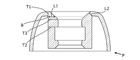
- FIG. 3 is a cross-sectional view of the earpiece of FIG. 2 taken along the line AA.
- FIG. 3 is a cross-sectional view of the earpiece of FIG. 2 taken along the line AA.
- FIG. 7 is a sectional view of the earpiece of FIG. 6 taken along the line BB.
- FIG. 7 is a sectional view of the earpiece of FIG. 6 taken along the line BB. It is sectional drawing which shows a mode that the outer cylinder part with which the earpiece of FIG. 6 is equipped is deform
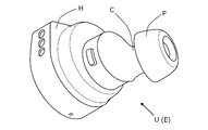
- FIG. 1 is a perspective view showing an embodiment of an earphone according to the present invention.
- the earphone E includes a sound emitting unit U for the left ear and a sound emitting unit (not shown) for the right ear.
- the figure shows only the sound emitting unit U for the left ear.
- the configuration of the sound emitting unit for the right ear is the same as the configuration of the sound emitting unit for the left ear.
- the figure shows a so-called completely wireless canal earphone in which a pair of left and right sound emitting units (a sound emitting unit for the left ear and a sound emitting unit for the right ear) are not connected by a cord.
- the earphone according to the present invention is not limited to this, and may be, for example, a canal type earphone in which a pair of left and right sound emitting units are connected by a cord.
- the following is an example of the sound emitting unit for the left ear.
- the sound emitting unit U includes a housing H, a sound conduit C, and an earpiece P.
- the earpiece P is an earpiece according to the present invention.
- the housing H houses a driver unit (not shown).
- the driver unit converts a sound signal (electrical signal) from a sound source (not shown) into a sound wave and outputs a sound wave according to the sound signal.
- the sound conduit C guides the sound wave from the driver unit to the outside of the housing H.
- the sound conduit C projects from the housing H.
- the sound conduit C guides a sound wave from the driver unit to the ear canal when the earphone E is mounted on the user's ear (hereinafter, referred to as “mounted state”).
- the earpiece P is attached to the inside of the ear canal of the user (inside the ear canal).
- the earpiece P is attached to the tip portion (not shown) of the sound conduit C.
- the earpiece P is made of a resin such as silicone rubber having elasticity.
- FIG. 2 is a perspective view showing an embodiment of the earpiece according to the present invention.
- 3 and 4 are cross-sectional views taken along the line AA of FIG.
- the earpiece P includes an inner cylinder part 1 and an outer cylinder part 2.
- a broken line T1 indicates a boundary between the inner tubular portion 1 and the outer tubular portion 2.
- the inner cylinder part 1 is attached to the sound conduit C (see FIG. 1).
- the inner tube portion 1 guides a sound wave from the driver unit guided to the sound conduit C to the outside of the earpiece P (external ear canal of the user).
- the specific configuration of the inner tubular portion 1 will be described later.
- the outer tube portion 2 is connected to the inner tube portion 1 at one end (upper side of FIG. 3).
- the outer tubular portion 2 covers the outer surface of the inner tubular portion 1 (the outer surface 1b described later).
- the outer tubular portion 2 is in close contact with the inner wall of the user's ear canal when worn.
- the specific configuration of the outer cylinder portion 2 will be described later.
- the inner cylinder portion 1 includes an inner surface 1a, an outer surface 1b, a fitting portion 11, and a sound guide portion 12.
- the broken line T2 indicates the boundary between the fitting portion 11 and the sound guide portion 12.
- the inner cylindrical portion 1 has a substantially cylindrical shape with one end (an upper end on the paper surface of FIG. 3) and the other end (a lower end on the paper surface of FIG. 3) opening.
- the inner surface 1a is connected to the outer surface 2b of the outer cylindrical portion 2 described below at one end side.
- the inner surface 1a is a surface of an inner circumference from one end to the other end of the inner tubular portion 1.
- the outer surface 1b is connected to the inner surface 2a of the outer cylindrical portion 2 described below at one end side.
- the outer surface 1b is the outer peripheral surface from the other end of the inner tubular portion 1 to a boundary portion B described later.
- the fitting part 11 is fitted to the tip of the sound conduit C (see FIG. 1).
- the fitting portion 11 is arranged on the other end side of the inner tubular portion 1.
- the fitting portion 11 includes an inner surface 11a.
- the inner surface 11a is in close contact with the outer surface of the sound conduit C.
- the sound conducting section 12 guides the sound wave from the driver unit guided to the sound conduit C to the ear canal of the user in the mounted state.
- the sound guide portion 12 is arranged on one end side of the inner tubular portion 1 and adjacent to the fitting portion 11.
- the sound guide portion 12 includes a constant diameter portion 121 and a diameter enlarged portion 122.
- a broken line T3 indicates a boundary between the constant diameter portion 121 and the enlarged diameter portion 122.
- the constant diameter part 121 is arranged adjacent to one end side of the fitting part 11.
- the constant diameter portion 121 includes an inner surface 121a.
- the inner diameter of the constant diameter portion 121 is constant from the other end side toward the one end side.
- the inner diameter of the constant diameter portion 121 is smaller than the inner diameter of the fitting portion 11. Therefore, a step portion is arranged between the inner surface 121a of the constant diameter portion 121 and the inner surface 11a of the fitting portion 11.
- the enlarged diameter portion 122 is arranged adjacent to one end side of the constant diameter portion 121.
- the inner diameter of the enlarged diameter portion 122 continuously increases from the other end side toward the one end side.
- the expanded diameter portion 122 includes an inner surface 122a.
- the inner surface 122a is, for example, an inclined surface that is continuously inclined from the other end side toward the one end side.
- the inclined surface is, for example, a linear surface that continuously inclines from the other end side to the one end side of the inner surface 122a.
- the inner surface of the expanded portion is not limited to a straight surface. That is, for example, the inner surface of the expanded diameter portion may be an arcuate surface as long as it is a surface that continuously expands from the other end side toward the one end side.
- the inner surface 11a of the fitting portion 11, the inner surface 121a of the constant diameter portion 121, and the inner surface 122a of the expanded diameter portion 122 form the inner surface 1a of the inner cylindrical portion 1.
- the outer cylinder part 2 is provided with the inner surface 2a and the outer surface 2b.
- the inner surface 2a is connected to the outer surface 1b of the inner tubular portion 1 on one end side.
- the outer surface 2b is connected to the inner surface 1a of the inner tubular portion 1 at one end side.
- the other end side of the outer tubular portion 2 extends in an umbrella shape toward the other end side of the inner tubular portion 1.
- the outer surface 2b is in close contact with the inner wall of the user's ear canal when worn.
- the outer surface 2b is deformed (crushed) when the earpiece P is inserted into the ear canal of the user.
- the outer cylinder part may be molded integrally with the inner cylinder part, or may be molded separately from the inner cylinder part.
- FIG. 4 shows the length between the respective parts of the earpiece P.
- the boundary between the inner surface 2a of the outer tubular portion 2 and the outer surface 1b of the inner tubular portion 1 constitutes a boundary portion B.
- the boundary portion B is an annular boundary line.
- An end portion on the other end side of the expanded diameter portion 122 of the inner tubular portion 1 (an end portion on the one end side of the constant diameter portion 121), which is indicated by a broken line T3, in the axial direction of the inner tubular portion 1 (vertical direction in the drawing), It is located (disposed) on the other end side of the boundary B.
- the length (L1) of the expanded diameter portion 122 (inner cylinder portion 1) in the radial direction (left-right direction of the paper surface), that is, the length between the inner surface 122a of the expanded diameter portion 122 and the outer surface 1b of the inner cylinder portion 1 is , The shortest at the boundary portion B among the axial positions on the outer surface 1b.
- the length (L2) between the inner surface 122a and the boundary portion B in the direction perpendicular to the inner surface 122a of the expanded diameter portion 122 is shorter than the radial length between the inner surface 1a and the outer surface 1b of the inner tubular portion 1. ..
- the length between the inner surface of the enlarged diameter portion and the boundary portion B in the normal direction of the inner surface of the enlarged diameter portion is the inner surface and the outer surface of the inner cylindrical portion. Shorter than the radial length between and.
- FIG. 5 is a cross-sectional view showing how the earpiece P is deformed. This figure shows a state in which the outer tubular portion 2 bends from the boundary portion B toward the inner tubular portion 1 side and the diameter of the outer tubular portion 2 is reduced. A two-dot chain line shown in the figure shows the outer cylinder portion 2 which is bent toward the inner cylinder portion 1 side from the boundary portion B as a starting point and has a reduced diameter.
- the outer tube portion 2 is inserted into the user's ear canal while being curved toward the central axis of the inner tube portion 1.
- the outer tube portion 2 is deformed to fit the shape of the inner wall of the ear canal.
- stress is likely to be applied to the earpiece P at the end portion on the one end side of the outer tubular portion 2.
- the radial length L1 of the expanded diameter portion 122 (the inner cylindrical portion 1) is the shortest at the boundary portion B.
- the length L2 in the perpendicular direction between the inner surface 122a and the boundary portion B is shorter than the radial length between the inner surface 1a and the outer surface 1b of the inner tubular portion 1. Further, the same length L2 is the shortest in the length between the inner surface 122a of the expanded diameter portion 122 and the outer surface 1b of the inner tubular portion 1. In other words, in the inner tubular portion 1, the thickness between the inner surface 122a of the expanded diameter portion 122 and the outer surface 1b of the inner tubular portion 1 is the thinnest at the boundary portion B.
- the outer cylinder part 2 bends starting from the boundary part B. Therefore, when the earpiece P is inserted into the ear canal, the outer tube portion 2 bends from the boundary portion B as a starting point. That is, the diameter of the outer tubular portion 2 is reduced.
- the tip of the expanded diameter portion 122 of the inner tubular portion 1 may bend from the boundary portion as a starting point depending on the size of the user's ear canal.
- the inner diameter of the expanded diameter portion 122 increases from the other end side toward the one end side. Therefore, even if the tip (end portion on the one end side) of the expanded diameter portion 122 bends, the expanded diameter portion 122 does not bend to the inside (center side) of the constant diameter portion 121 of the inner tubular portion 1.
- the constant diameter portion 121 of the inner tubular portion 1 does not bend. Therefore, the inner diameter of the distal end side of the inner tubular portion 1, particularly the inner diameter of the constant diameter portion 121 does not change before and after the insertion into the ear canal of the user. As a result, the sound quality of the sound waves guided to the ear canal is not affected.
- the outer diameter of the outer tube portion 2 becomes small, so that the earpiece P is easily inserted into the ear canal.
- the outer tube portion 2 tends to return to its original shape (diameter) when inserted into the ear canal. Therefore, the earpiece P is firmly fixed in the ear canal of the user. As a result, the earpiece P is less likely to fall off the ear canal of the user.
- the outer tubular portion 2 is bent from the boundary portion B as a starting point, and depending on the size of the ear canal of the user, the enlarged diameter portion 122 of the inner tubular portion 1 is formed.
- the tip bends.
- the enlarged diameter portion 122 does not bend to the inside of the constant diameter portion 121 of the inner tubular portion 1.
- the constant diameter portion 121 of the inner tubular portion 1 does not bend. Therefore, the inner diameter of the constant diameter portion 121 of the sound guide portion 12 does not change before and after the earpiece P is mounted in the ear canal of the user. That is, the sound quality of the sound wave guided by the sound conduit C and passing through the sound guide portion 12 is not affected.
- the earpiece P is deformed so that the outer tubular portion 2 conforms to the shape of the inner wall of the ear canal of the user in the worn state.
- the constant diameter portion 121 of the inner tubular portion 1 does not deform in the mounted state, and the sound quality of the sound wave passing through the sound guide portion 12 is not affected. That is, the earpiece P prevents deterioration of sound quality while ensuring wearability.
- the sound waves from the driver unit are guided to the user's ear canal after being repeatedly reflected in the sound conduit and sound conducting section.
- the sound wave from the driver unit is attenuated by reflection inside the sound conduit and inside the sound guide.
- the characteristics of the high-pitched sound range (hereinafter, referred to as “high-range characteristics”) are deteriorated.
- the sound guide portion 12 includes the enlarged diameter portion 122, and the inner diameter of the enlarged diameter portion 122 continuously increases from the other end side toward the one end side. Therefore, the sound wave passing through the sound guide portion 12 is reduced in the degree and number of reflections at the expanded diameter portion 122. Therefore, deterioration of high-pitched sound characteristics due to attenuation of sound waves is suppressed.
- the difference between the earpiece of the present embodiment (hereinafter referred to as the “second embodiment”) and the earpiece of the first embodiment is the presence/absence of the enlarged diameter portion and the presence/absence of a groove portion described later. That is, the earpiece PX of the second embodiment does not include the expanded diameter portion 122 included in the earpiece P of the first embodiment. Moreover, the earpiece PX of the second embodiment includes a groove portion 14X described later.
- FIG. 6 is a perspective view showing another embodiment of the earpiece according to the present invention.
- 7 and 8 are sectional views taken along the line BB of FIG.
- the earpiece PX includes an inner tubular portion 1X and an outer tubular portion 2X.
- a broken line TX1 indicates a boundary between the inner tubular portion 1X and the outer tubular portion 2X.
- the inner cylinder 1X is attached to the sound conduit C (see FIG. 1).
- the inner tube portion 1X guides the sound wave from the driver unit guided to the sound conduit C to the outside of the earpiece PX (the ear canal of the user).
- the inner tubular portion 1X has a substantially cylindrical shape with one end (an upper end on the paper surface of FIG. 7) and the other end (a lower end on the paper surface of FIG. 7) opening. The specific configuration of the inner tubular portion 1 will be described later.
- the outer tubular portion 2X is connected to the inner tubular portion 1X at one end (upper side of FIG. 7).
- the outer tubular portion 2X covers the outer surface (the outer surface 1Xb described later) of the inner tubular portion 1X.
- the outer tubular portion 2X is in close contact with the inner wall of the user's ear canal when worn.
- the specific configuration of the outer cylinder portion 2X will be described later.
- the inner tube section 1X includes an inner surface 1Xa, an outer surface 1Xb, a fitting section 11X, a sound guide section 12X, a top surface 13X, and a groove section 14X.
- the broken line TX2 indicates the boundary between the fitting portion 11X and the sound guide portion 12X.
- the inner surface 1Xa is a surface of the inner circumference from one end to the other end of the inner cylindrical portion 1X.
- the outer surface 1Xb is connected to the inner surface 2Xa of the outer cylindrical portion 2X described later at one end side.
- the outer surface 1Xb is the outer peripheral surface from the other end of the inner cylindrical portion 1X to a boundary portion BX described later.
- the fitting part 11X is fitted to the tip of the sound conduit C (see FIG. 1).
- the fitting portion 11X is arranged on the other end side of the inner tubular portion 1X.
- the fitting portion 11X includes an inner surface 11Xa.
- the inner surface 11Xa is in close contact with the outer surface of the sound conduit C.
- the sound conducting portion 12X guides the sound wave from the driver unit guided to the sound conduit C (see FIG. 1) to the user's ear canal in the mounted state.
- the sound guide portion 12X is arranged on one end side of the inner tubular portion 1X and adjacent to the fitting portion 11X.
- the shape of the sound guide portion 12X is a cylindrical shape with a constant inner diameter.
- the inner diameter of the sound guide portion 12X is constant from the other end side toward the one end side.
- the inner diameter of the sound guide portion 12X is smaller than the inner diameter of the fitting portion 11X. Therefore, a step portion is arranged between the inner surface 12Xa of the sound guide portion 12X and the inner surface 11Xa of the fitting portion 11X.
- the sound guide section may include a diameter expansion section. That is, for example, the sound guide portion includes the constant diameter portion and the diameter enlarged portion, as in the first embodiment.
- the constant diameter portion is arranged adjacent to one end side of the fitting portion.
- the enlarged diameter portion is arranged adjacent to one end side of the constant diameter portion.
- the inner diameter of the expanded diameter portion continuously increases from the other end side toward the one end side.
- the sound guide portion may have only the inner diameter to be expanded (only the expanded diameter portion), instead of the constant diameter inner diameter. That is, for example, the sound guide portion includes a diameter expansion portion.
- the expanded diameter portion is arranged adjacent to one end side of the fitting portion. The inner diameter of the expanded diameter portion continuously increases from the other end side toward the one end side.
- the inner surface 11Xa of the fitting portion 11X and the inner surface 12Xa of the sound guide portion 12X form the inner surface 1Xa of the inner tubular portion 1X.
- the top surface 13X is an open end surface on one end side of the inner cylindrical portion 1X.
- the groove portion 14X is a groove having a substantially V-shaped cross section, which is formed by cutting out a part of the top surface 13X.
- the groove portion 14X is an annular groove.
- the groove portion 14X is arranged concentrically with the inner surface 1Xa (inner surface 11Xa and inner surface 12Xa) of the inner cylindrical portion 1X.
- the groove portion 14X includes a first side surface 141X and a second side surface 142X.
- the first side surface 141X is a surface parallel to the inner surface 12Xa of the sound guide portion 12X. That is, the diameter of the first side surface 141X is a constant diameter.
- the second side surface 142X is arranged on the inner cylinder portion 1X outside the first side surface 141X in the radial direction of the inner cylinder portion 1X (left-right direction on the paper surface of FIG. 7).
- the second side surface 142X is an inclined surface that is inclined outward from the other end side toward the one end side.
- the inclined surface is, for example, a linear surface that continuously inclines outward from the other end of the second side surface 142X toward the one end.
- the second side surface is not limited to a linear surface. That is, for example, the second side surface may be an arcuate surface as long as it is a surface that continuously expands outward from the other end side toward the one end side.
- one end side of the second side surface may be located in the outer cylinder part.
- the top surface includes a part of the outer surface of the outer cylindrical portion.
- the bottom portion 143X is disposed below the inner cylinder portion 1X in the axial direction (vertical direction in the drawing of FIG. 7) and is connected to the first side surface 141X and the second side surface 142X, respectively.
- the bottom does not have to be a surface. That is, for example, the bottom portion may be a boundary line between the first side surface and the second side surface.
- the outer cylinder part 2X is provided with the inner surface 2Xa and the outer surface 2Xb.
- the inner surface 2Xa is connected to the outer surface 1Xb of the inner tubular portion 1X at one end side.
- the outer surface 2Xb is connected to the second side surface 142X of the groove portion 14X at one end side.
- the other end side of the outer tubular portion 2X extends in an umbrella shape toward the other end side of the inner tubular portion 1X.
- the outer surface 2Xb is in close contact with the inner wall of the user's ear canal when worn.
- the outer surface 2Xb is deformed (crushed) when the earpiece PX is inserted into the ear canal of the user.
- the outer cylinder part may be molded integrally with the inner cylinder part, or may be molded separately from the inner cylinder part.
- FIG. 8 shows a length between respective parts of the earpiece PX.
- the boundary between the inner surface 2Xa of the outer cylindrical portion 2X and the outer surface 1Xb of the inner cylindrical portion 1X constitutes a boundary portion BX.
- the boundary portion BX is an annular boundary line.
- the bottom portion 143X of the groove portion 14X is located (disposed) on the other end side of the boundary portion B in the axial direction of the inner tubular portion 1X (vertical direction on the paper surface).
- the radial length (L3) between the second side surface 142X and the outer surface 1b of the inner tubular portion 1X is the diameter between the inner surface 1Xa and the outer surface 1Xb of the inner tubular portion 1X in the radial direction of the inner tubular portion 1X. Shorter than the length of the direction. The same length L3 is the shortest at the boundary portion BX among the axial positions on the outer surface 1b.
- the length (L4) between the second side surface 142X and the boundary portion BX in the perpendicular direction of the second side surface 142X is larger than the radial length between the second side surface 142X and the outer surface 1Xb of the inner tubular portion 1X. short.
- the length between the second side surface and the boundary portion B in the normal direction of the second side surface is between the second side surface and the outer surface of the inner tubular portion. Shorter than the radial length.
- FIG. 9 is a cross-sectional view showing how the earpiece PX is deformed. This figure shows how the outer cylinder portion 2X bends toward the inner cylinder portion 1X from the boundary portion BX and the diameter of the outer cylinder portion 2X is reduced. The two-dot chain line shown in the figure shows the outer cylinder portion 2X whose diameter is reduced by bending toward the inner cylinder portion 1X from the boundary portion BX.
- the outer tube portion 2X is inserted into the user's ear canal in a state of being curved toward the central axis of the inner tube portion 1X.
- the outer tube portion 2X is deformed to fit the shape of the inner wall of the ear canal.
- stress tends to be applied to the earpiece PX at the end portion on the one end side of the outer tubular portion 2X.
- the radial length L3 between the second side surface 142X and the outer surface 1b of the inner cylindrical portion 1X is greater than the radial length L3 between the inner surface 1Xa and the outer surface 1b of the inner cylindrical portion 1X. Is also short.
- the same length L3 is the shortest at the boundary portion BX among the axial positions of the outer surface 1Xb.
- the length L4 of the second side surface 142X in the perpendicular direction between the second side surface 142X and the boundary portion BX is shorter than the radial length between the second side surface 142X and the outer surface 1Xb of the inner tubular portion 1X. ..
- the same length L4 is the shortest (thinnest) in the length between the second side surface 142X and the outer surface 1Xb of the inner tubular portion 1X. In other words, in the inner cylinder portion 1X, the thickness between the second side surface 142X and the outer surface 1Xb is the smallest at the boundary portion BX.
- the outer cylinder portion 2X bends starting from the boundary portion BX. Moreover, the groove portion 14X is arranged in the inner cylinder portion 1X. Therefore, when the earpiece PX is inserted into the ear canal, the outer tube portion 2 bends starting from the boundary portion BX. That is, the diameter of the outer tubular portion 2 is reduced.
- the groove 14X is arranged in the inner cylinder 1X, so that the inner side of the groove 14X of the sound guide 12X of the inner cylinder 1X does not bend. Therefore, the inner diameter of the sound guide portion 12X does not change before and after being inserted into the ear canal of the user. That is, the inner diameter of the sound guide portion 12X does not decrease even in the mounted state. As a result, the sound quality of the sound waves guided to the ear canal is not affected.
- the outer diameter of the outer tube portion 2X becomes small, so that the earpiece PX is easily inserted into the ear canal.
- the outer tube portion 2X tends to return to its original shape (diameter) when inserted into the ear canal. Therefore, the earpiece PX is firmly fixed in the ear canal of the user. As a result, the earpiece PX is less likely to fall off the ear canal of the user.
- the outer tubular portion 2X bends from the boundary portion BX as a starting point, while the inner portion does not bend inside the groove portion 14X of the inner tubular portion 1X. Therefore, the inner diameter of the sound guide portion 12X does not change before and after the earpiece PX is mounted in the ear canal of the user. That is, the sound quality of the sound wave guided by the sound conduit C and passing through the sound guide portion 12X is not affected.
- the earpiece PX is deformed so that the outer cylinder portion 2X conforms to the shape of the inner wall of the ear canal of the user in the mounted state.
- the sound guide part 12X of the inner cylinder part 1X is not deformed in the mounted state, and the sound quality of the sound wave passing through the sound guide part 12X is not affected. That is, the earpiece PX prevents deterioration of sound quality while ensuring wearability.
- An outer cylinder body (for example, the outer cylinder portion 2) to be inserted into the ear canal and a sound conduit (for example, the sound conduit C) of the unit case (for example, the housing H) that is bent inward from the tip end portion of the outer cylinder body.
- an inner cylinder body (for example, the inner cylinder part 1) attached to the unit case is provided, and the outer cylinder body and the inner cylinder body are integrally molded by an elastic material (for example, an earpiece P).
- a tip bending portion for example, a boundary portion B
- a thin-walled portion for example, an expanded portion
- An annular V-shaped groove (for example, a groove portion 14X) having a V-shaped cross section in the axial direction is formed along the tip bending portion, and the V-shaped groove and the folded back surface of the tip bending portion are provided. And the thin portion (for example, the length L4 of the second side surface 142X in the perpendicular direction between the second side surface 142X and the boundary portion BX) is formed.
- the earpiece described in any one.
- a tapered opening for example, an enlarged diameter portion 122 that reduces the inner diameter is formed from the tip bending portion toward the inner cylindrical body, and the thin wall is provided between the tapered opening and the folded back surface of the tip bending portion.
- the earpiece according to any one of features 1 to 3, wherein a portion (for example, a vertical length L2 between the inner surface 122a of the expanded diameter portion 122 and the boundary portion B) is formed.
- a cylindrical opening having the same inner diameter is formed from the tip bent portion toward the inner cylindrical body, and the thin portion is formed between the cylindrical opening and the folded back surface of the tip bent portion.
- An earpiece for example, an earpiece P
- a unit case for example, a housing H
- An earphone for example, an earphone in which an inner tube body (for example, the inner tube portion 1) of the earpiece is attached so as to cover a sound conduit (for example, sound conduit C) formed in the unit case.
- E an inner tube body (for example, the inner tube portion 1) of the earpiece is attached so as to cover a sound conduit (for example, sound conduit C) formed in the unit case.
Landscapes
- Engineering & Computer Science (AREA)
- Physics & Mathematics (AREA)
- Acoustics & Sound (AREA)
- Signal Processing (AREA)
- Health & Medical Sciences (AREA)
- Otolaryngology (AREA)
- Manufacturing & Machinery (AREA)
- General Health & Medical Sciences (AREA)
- Neurosurgery (AREA)
- Headphones And Earphones (AREA)
Abstract
Priority Applications (5)
| Application Number | Priority Date | Filing Date | Title |
|---|---|---|---|
| CN202410054939.XA CN117880684A (zh) | 2019-01-29 | 2020-01-29 | 听筒及耳机 |
| JP2020569684A JP7487940B2 (ja) | 2019-01-29 | 2020-01-29 | イヤピースおよびイヤホン |
| US17/426,298 US12256184B2 (en) | 2019-01-29 | 2020-01-29 | Earpiece and earphone |
| EP20748575.6A EP3920548A4 (fr) | 2019-01-29 | 2020-01-29 | Écouteur et oreillette |
| CN202080011286.7A CN113366860B (zh) | 2019-01-29 | 2020-01-29 | 听筒及耳机 |
Applications Claiming Priority (2)
| Application Number | Priority Date | Filing Date | Title |
|---|---|---|---|
| JP2019013432 | 2019-01-29 | ||
| JP2019-013432 | 2019-01-29 |
Publications (1)
| Publication Number | Publication Date |
|---|---|
| WO2020158802A1 true WO2020158802A1 (fr) | 2020-08-06 |
Family
ID=71841358
Family Applications (1)
| Application Number | Title | Priority Date | Filing Date |
|---|---|---|---|
| PCT/JP2020/003180 Ceased WO2020158802A1 (fr) | 2019-01-29 | 2020-01-29 | Écouteur et oreillette |
Country Status (5)
| Country | Link |
|---|---|
| US (1) | US12256184B2 (fr) |
| EP (1) | EP3920548A4 (fr) |
| JP (1) | JP7487940B2 (fr) |
| CN (2) | CN117880684A (fr) |
| WO (1) | WO2020158802A1 (fr) |
Families Citing this family (10)
| Publication number | Priority date | Publication date | Assignee | Title |
|---|---|---|---|---|
| USD964323S1 (en) * | 2020-09-27 | 2022-09-20 | Realme Mobile Telecommunications (Shenzhen) Co., Ltd. | Case with earphones |
| USD991225S1 (en) * | 2020-12-07 | 2023-07-04 | Bang & Olufsen A/S | Earphone |
| USD973637S1 (en) * | 2021-01-12 | 2022-12-27 | Target Brands, Inc. | Earphone |
| USD989043S1 (en) * | 2021-01-27 | 2023-06-13 | New Audio LLC | Earphone |
| USD995469S1 (en) * | 2021-06-04 | 2023-08-15 | Bang & Olufsen A/S | Earphone |
| JP1701663S (fr) * | 2021-06-09 | 2021-12-06 | ||
| USD1013663S1 (en) * | 2021-08-19 | 2024-02-06 | Harman International Industries, Incorporated | Headphone |
| USD1033394S1 (en) * | 2021-08-24 | 2024-07-02 | Sony Group Corporation | Earphone |
| TWD222256S (zh) * | 2021-10-27 | 2022-11-21 | 法商路易威登馬爾悌耶公司 | 耳機 |
| USD1053171S1 (en) * | 2023-02-13 | 2024-12-03 | Person-Aiz As | Earbud |
Citations (7)
| Publication number | Priority date | Publication date | Assignee | Title |
|---|---|---|---|---|
| US6513621B1 (en) * | 2000-06-13 | 2003-02-04 | Doctors Research Group | Method of producing and making use of ear tips having a filled airtight chamber |
| WO2012144040A1 (fr) * | 2011-04-20 | 2012-10-26 | パイオニア株式会社 | Écouteurs |
| JP2013038756A (ja) | 2011-08-05 | 2013-02-21 | Hua Mao International Co Ltd | イヤホンのイヤーピース |
| WO2014041613A1 (fr) * | 2012-09-11 | 2014-03-20 | パイオニア株式会社 | Écouteurs |
| JP2015056782A (ja) * | 2013-09-12 | 2015-03-23 | 株式会社Jvcケンウッド | イヤーピース及びそれを備えたイヤホン |
| JP2015061206A (ja) * | 2013-09-19 | 2015-03-30 | 株式会社Jvcケンウッド | イヤーピース及びそれを備えたイヤホン |
| JP3218417U (ja) | 2018-08-02 | 2018-10-11 | Ttr株式会社 | イヤーピース及びそれを用いたイヤホン |
Family Cites Families (4)
| Publication number | Priority date | Publication date | Assignee | Title |
|---|---|---|---|---|
| US8348010B2 (en) * | 2007-10-19 | 2013-01-08 | Apple Inc. | Invertible ear tips for an ear piece |
| JP2011228833A (ja) * | 2010-04-16 | 2011-11-10 | Molex Inc | イヤホン |
| TWM469709U (zh) * | 2013-07-05 | 2014-01-01 | Jetvox Acoustic Corp | 調音耳機 |
| KR101545087B1 (ko) * | 2014-04-17 | 2015-08-17 | 채승호 | 귀마개와 이를 가지는 귀마개 세트 |
-
2020
- 2020-01-29 CN CN202410054939.XA patent/CN117880684A/zh active Pending
- 2020-01-29 CN CN202080011286.7A patent/CN113366860B/zh active Active
- 2020-01-29 JP JP2020569684A patent/JP7487940B2/ja active Active
- 2020-01-29 WO PCT/JP2020/003180 patent/WO2020158802A1/fr not_active Ceased
- 2020-01-29 EP EP20748575.6A patent/EP3920548A4/fr active Pending
- 2020-01-29 US US17/426,298 patent/US12256184B2/en active Active
Patent Citations (7)
| Publication number | Priority date | Publication date | Assignee | Title |
|---|---|---|---|---|
| US6513621B1 (en) * | 2000-06-13 | 2003-02-04 | Doctors Research Group | Method of producing and making use of ear tips having a filled airtight chamber |
| WO2012144040A1 (fr) * | 2011-04-20 | 2012-10-26 | パイオニア株式会社 | Écouteurs |
| JP2013038756A (ja) | 2011-08-05 | 2013-02-21 | Hua Mao International Co Ltd | イヤホンのイヤーピース |
| WO2014041613A1 (fr) * | 2012-09-11 | 2014-03-20 | パイオニア株式会社 | Écouteurs |
| JP2015056782A (ja) * | 2013-09-12 | 2015-03-23 | 株式会社Jvcケンウッド | イヤーピース及びそれを備えたイヤホン |
| JP2015061206A (ja) * | 2013-09-19 | 2015-03-30 | 株式会社Jvcケンウッド | イヤーピース及びそれを備えたイヤホン |
| JP3218417U (ja) | 2018-08-02 | 2018-10-11 | Ttr株式会社 | イヤーピース及びそれを用いたイヤホン |
Non-Patent Citations (1)
| Title |
|---|
| See also references of EP3920548A4 |
Also Published As
| Publication number | Publication date |
|---|---|
| CN113366860A (zh) | 2021-09-07 |
| CN113366860B (zh) | 2024-10-18 |
| JP7487940B2 (ja) | 2024-05-21 |
| CN117880684A (zh) | 2024-04-12 |
| EP3920548A1 (fr) | 2021-12-08 |
| JPWO2020158802A1 (fr) | 2020-08-06 |
| US12256184B2 (en) | 2025-03-18 |
| US20220109922A1 (en) | 2022-04-07 |
| EP3920548A4 (fr) | 2023-07-19 |
Similar Documents
| Publication | Publication Date | Title |
|---|---|---|
| JP7487940B2 (ja) | イヤピースおよびイヤホン | |
| JP5392796B2 (ja) | イヤーチップ及びそれを具備するイヤホン | |
| JP7151094B2 (ja) | イヤホン及びサポータ | |
| KR102310442B1 (ko) | 이어폰 | |
| US8270648B2 (en) | Earpiece and electro-acoustic transducer | |
| CN102119535A (zh) | 耳机装置及耳机装置主体 | |
| US20220070572A1 (en) | Variable eartip for earphone | |
| JP2011009909A (ja) | イヤホン | |
| JP2019500803A (ja) | 汎用の音響口取付け用コアを備えたイヤホンチップ | |
| WO2009157125A1 (fr) | Puce d'oreille et écouteur à introduction | |
| JP2018006784A5 (fr) | ||
| JP5550289B2 (ja) | カナル型イヤホン | |
| US20120155691A1 (en) | Wired earphone | |
| JPWO2016067681A1 (ja) | 音響変換装置 | |
| JP3193854U (ja) | カナル型イヤホンマイクアセンブリ | |
| JP6482600B2 (ja) | インイヤー型イヤホン用のカバー | |
| CN215499510U (zh) | 耳塞及耳机装置 | |
| JP5665792B2 (ja) | イヤーチップ | |
| CN207184751U (zh) | 入耳式耳机 | |
| JP2010130034A (ja) | イヤホン装置 | |
| KR102163066B1 (ko) | 이어 팁 및 이를 갖춘 이어폰 | |
| JP2020136963A (ja) | ウェアラブルスピーカシステム | |
| JP5488499B2 (ja) | カナル型イヤホン | |
| WO2025104414A1 (fr) | Dispositif d'amélioration de la qualité sonore | |
| JP6284967B2 (ja) | イヤホン |
Legal Events
| Date | Code | Title | Description |
|---|---|---|---|
| 121 | Ep: the epo has been informed by wipo that ep was designated in this application |
Ref document number: 20748575 Country of ref document: EP Kind code of ref document: A1 |
|
| DPE1 | Request for preliminary examination filed after expiration of 19th month from priority date (pct application filed from 20040101) | ||
| ENP | Entry into the national phase |
Ref document number: 2020569684 Country of ref document: JP Kind code of ref document: A |
|
| NENP | Non-entry into the national phase |
Ref country code: DE |
|
| ENP | Entry into the national phase |
Ref document number: 2020748575 Country of ref document: EP Effective date: 20210830 |
|
| WWG | Wipo information: grant in national office |
Ref document number: 17426298 Country of ref document: US |